EP3006762A1 - Piston-integrated seal - Google Patents
Piston-integrated seal Download PDFInfo
- Publication number
- EP3006762A1 EP3006762A1 EP13885064.9A EP13885064A EP3006762A1 EP 3006762 A1 EP3006762 A1 EP 3006762A1 EP 13885064 A EP13885064 A EP 13885064A EP 3006762 A1 EP3006762 A1 EP 3006762A1
- Authority
- EP
- European Patent Office
- Prior art keywords
- hydraulic chamber
- clutch
- seal
- edge portion
- piston
- Prior art date
- Legal status (The legal status is an assumption and is not a legal conclusion. Google has not performed a legal analysis and makes no representation as to the accuracy of the status listed.)
- Granted
Links
Images



Classifications
-
- F—MECHANICAL ENGINEERING; LIGHTING; HEATING; WEAPONS; BLASTING
- F16—ENGINEERING ELEMENTS AND UNITS; GENERAL MEASURES FOR PRODUCING AND MAINTAINING EFFECTIVE FUNCTIONING OF MACHINES OR INSTALLATIONS; THERMAL INSULATION IN GENERAL
- F16D—COUPLINGS FOR TRANSMITTING ROTATION; CLUTCHES; BRAKES
- F16D25/00—Fluid-actuated clutches
- F16D25/12—Details not specific to one of the before-mentioned types
-
- F—MECHANICAL ENGINEERING; LIGHTING; HEATING; WEAPONS; BLASTING
- F16—ENGINEERING ELEMENTS AND UNITS; GENERAL MEASURES FOR PRODUCING AND MAINTAINING EFFECTIVE FUNCTIONING OF MACHINES OR INSTALLATIONS; THERMAL INSULATION IN GENERAL
- F16D—COUPLINGS FOR TRANSMITTING ROTATION; CLUTCHES; BRAKES
- F16D25/00—Fluid-actuated clutches
- F16D25/06—Fluid-actuated clutches in which the fluid actuates a piston incorporated in, i.e. rotating with the clutch
- F16D25/062—Fluid-actuated clutches in which the fluid actuates a piston incorporated in, i.e. rotating with the clutch the clutch having friction surfaces
- F16D25/063—Fluid-actuated clutches in which the fluid actuates a piston incorporated in, i.e. rotating with the clutch the clutch having friction surfaces with clutch members exclusively moving axially
- F16D25/0635—Fluid-actuated clutches in which the fluid actuates a piston incorporated in, i.e. rotating with the clutch the clutch having friction surfaces with clutch members exclusively moving axially with flat friction surfaces, e.g. discs
- F16D25/0638—Fluid-actuated clutches in which the fluid actuates a piston incorporated in, i.e. rotating with the clutch the clutch having friction surfaces with clutch members exclusively moving axially with flat friction surfaces, e.g. discs with more than two discs, e.g. multiple lamellae
-
- F—MECHANICAL ENGINEERING; LIGHTING; HEATING; WEAPONS; BLASTING
- F16—ENGINEERING ELEMENTS AND UNITS; GENERAL MEASURES FOR PRODUCING AND MAINTAINING EFFECTIVE FUNCTIONING OF MACHINES OR INSTALLATIONS; THERMAL INSULATION IN GENERAL
- F16J—PISTONS; CYLINDERS; SEALINGS
- F16J15/00—Sealings
- F16J15/16—Sealings between relatively-moving surfaces
- F16J15/32—Sealings between relatively-moving surfaces with elastic sealings, e.g. O-rings
- F16J15/3204—Sealings between relatively-moving surfaces with elastic sealings, e.g. O-rings with at least one lip
-
- F—MECHANICAL ENGINEERING; LIGHTING; HEATING; WEAPONS; BLASTING
- F16—ENGINEERING ELEMENTS AND UNITS; GENERAL MEASURES FOR PRODUCING AND MAINTAINING EFFECTIVE FUNCTIONING OF MACHINES OR INSTALLATIONS; THERMAL INSULATION IN GENERAL
- F16J—PISTONS; CYLINDERS; SEALINGS
- F16J15/00—Sealings
- F16J15/16—Sealings between relatively-moving surfaces
- F16J15/32—Sealings between relatively-moving surfaces with elastic sealings, e.g. O-rings
- F16J15/3204—Sealings between relatively-moving surfaces with elastic sealings, e.g. O-rings with at least one lip
- F16J15/3232—Sealings between relatively-moving surfaces with elastic sealings, e.g. O-rings with at least one lip having two or more lips
-
- F—MECHANICAL ENGINEERING; LIGHTING; HEATING; WEAPONS; BLASTING
- F16—ENGINEERING ELEMENTS AND UNITS; GENERAL MEASURES FOR PRODUCING AND MAINTAINING EFFECTIVE FUNCTIONING OF MACHINES OR INSTALLATIONS; THERMAL INSULATION IN GENERAL
- F16D—COUPLINGS FOR TRANSMITTING ROTATION; CLUTCHES; BRAKES
- F16D2300/00—Special features for couplings or clutches
- F16D2300/08—Details or arrangements of sealings not provided for in group F16D3/84
Definitions
- the present invention relates to a piston-integrated seal which is used in a hydraulic clutch of an automatic transmission in a vehicle.
- Fig. 4 shows a hydraulic clutch which employs a conventional piston-integrated seal
- Fig. 5 shows an outline structure of the conventional piston-integrated seal.
- reference numeral 1 denotes an annular clutch cylinder which rotates together with a drive shaft (not shown)
- reference numeral 2 denotes a clutch piston which is arranged within the clutch cylinder 1 so as to be movable in an axial direction, and defines a hydraulic chamber S1 between the clutch piston and an end plate portion 11 of the clutch cylinder
- reference numeral 3 denotes a spring holder which is arranged in a space S2 in an opposite side to the hydraulic chamber S1 as seen from the clutch piston 2 and is locked its inner diameter to an inner tube portion 13 of the clutch cylinder
- reference numeral 4 denotes a return spring which is interposed between the clutch piston 2 and the spring holder 3 in an appropriately compressed state
- reference numeral 5 denotes a multiple disc clutch constructed by a plurality of drive plates 51 which are locked to the clutch cylinder 1 side in a circumferential direction under a movable state in an axial direction, and a plurality of driven plates 52 which are locked to
- This kind of hydraulic clutch is structured such that the piston 2 displaces in an axial direction within the clutch cylinder 1 by applying a hydraulic pressure to the hydraulic chamber S1 via a pressure guide port 14 which is provided in the inner tube portion 13 of the clutch cylinder 1 or releasing the hydraulic pressure, thereby friction fastening the drive plate 51 and the driven plate 52 of the multiple disc clutch 5 or canceling the friction fastening so as to carry out a clutch connection and disconnection motion.
- a packing such as an O-ring has been conventionally used as a seal means for inner and outer peripheries of the clutch piston 2, however, the clutch piston 2 is desired to be lowered its friction in order to achieve an improvement of fuel consumption and a reduction of shift shock (a shock generated at the friction fastening time of the clutch).
- a piston-integrated seal 100 having seal lips 101 and 101 has been a mainstream, the seal lips 101 and 101 being slidably brought into close contact with the outer tube portion 12 and the inner tube portion 13 of the clutch cylinder 1 while being directed to the hydraulic chamber S1 side.
- the piston-integrated seal 100 is integrally formed in the clutch piston 2 by a rubber-like elastic material (a rubber material or a synthetic resin material having a rubber-like elasticity) (refer, for example, to the following patent document 1).
- the seal lip 101 is generally structured such that an angle ⁇ of an inclined surface closer to the hydraulic chamber S1 side than the seal edge portion where a contact pressure P (an interference L) in relation to the other sliding surface shown by a two-dot chain line in the drawing is the greatest is larger than an angle ⁇ of an inclined surface in an opposite side, and a length Ha in an axial direction from the seal edge portion to the root portion in the opposite side to the hydraulic chamber S1 is comparatively long.
- the friction can be reduced by forming a desired number of lubrication grooves in the sliding surface of the seal lip 101 (refer, for example, to the following patent document 2).
- it has been insufficient to reduce the friction difference caused by the directionality of the seal lip 101.
- a piston-integrated seal according to the invention of a first aspect has a seal lip which is integrally provided in a clutch piston of a hydraulic clutch and is directed to a hydraulic chamber side, the seal lip is structured such that a main seal edge portion in a hydraulic chamber side and a sub seal edge portion in an anti-hydraulic chamber side are formed in a sliding portion in relation to the other sliding surface, and the main seal edge portion and the sub seal edge portion are structured such that an angle of an inclined surface in the hydraulic chamber side is smaller than an angle of an inclined surface in the anti-hydraulic chamber side in a un-installed state, and the angle of the inclined surface in the hydraulic chamber side in relation to the other sliding surface is approximately equal to the angle of the inclined surface in the anti-hydraulic chamber side in an installed state.
- a piston-integrated seal according to the invention of a second aspect is the structure described in the first aspect, wherein an interference of the sub seal edge portion is smaller than an interference of the main seal edge portion.
- a piston-integrated seal according to the invention of a third aspect is the structure described in the first or second aspect, wherein the sub seal edge portion is positioned closer to the anti-hydraulic chamber side than a surface of a base portion in the hydraulic chamber side of the seal lip.
- the interference of the sub seal edge portion is smaller than the interference of the main seal edge portion, since the deformation of the main seal edge portion can be absorbed by the sub seal edge portion, change in contact load of the main seal edge portion in relation to the other sliding surface can be suppressed regardless of change of the hydraulic pressure acting on the seal lip. As a result, it is possible to reduce the difference between the friction at the stroking time to the hydraulic chamber side and the friction at the stroking time to the anti-hydraulic chamber side.
- the sub seal edge portion is positioned closer to the anti-hydraulic chamber side than the surface of the base portion in the hydraulic chamber side of the seal lip, since the deformation of the sub seal edge portion caused by applying the hydraulic pressure is suppressed, a seal lip deformation suppressing action by the sub seal edge portion is enhanced, and it is possible to improve the pressure resistance of the seal lip.
- Fig. 1 is a one-side cross sectional view showing the piston-integrated seal according to the embodiment together with a part of a hydraulic clutch
- reference numeral 1 denotes a clutch cylinder
- reference numeral 2 denotes a clutch piston which is arranged within the clutch cylinder 1 so as to be movable in an axial direction and defines a hydraulic chamber S1 between the clutch piston and the clutch cylinder
- reference numeral 1 denotes a spring holder which is arranged in a space (hereinafter, refer to as an anti-hydraulic chamber side space) S2 in an opposite side to the hydraulic chamber S1 as seen from the piston 2 and is locked to an inner tube portion 13 of the clutch cylinder 1 in its inner diameter portion
- reference numeral 4 denotes a return spring which is interposed in an appropriately compressed state between the clutch piston 2 and the spring holder 3
- reference numeral 5 denotes a multiple disc clutch.
- the clutch piston 2 is a metal press molded product, and has a pressure receiving portion 21 which is faced to the end plate portion 11 of the clutch cylinder 1 in an axial direction, an outer tube portion 22 which extends from an outer diameter portion of the pressure receiving portion 21 to the anti-hydraulic chamber side space S2 side and faces to the outer tube portion 12 of the clutch cylinder 1 in a radial direction, and an inner tube portion 23 which extends from an inner diameter portion of the pressure receiving portion 21 to an opposite side to the hydraulic chamber S1 and faces to the inner tube portion 13 of the clutch cylinder 1 in a radial direction.
- a clutch pressing portion 24 is formed in a leading end portion of the outer tube portion 22 of the clutch piston 2, and an inward collar portion 25 is formed in a leading end portion of the inner tube portion 13 of the clutch piston 2.
- the return spring 4 is structured such as to always energize the clutch piston 2 in a direction of reducing a cubic capacity of the hydraulic chamber S1 and is constructed by a coil spring. A plurality of return springs 4 are arranged at predetermined intervals in a circumferential direction.
- the multiple disc clutch 5 is structured such that a plurality of drive plates 51 and a plurality of driven plates 52 are arranged alternately in an axial direction.
- the drive plates 51 are locked to the outer tube portion of the clutch cylinder 1 in a circumferential direction in a state in which the drive plates 51 can move in an axial direction
- the driven plates 52 are locked to a clutch hub 53 provided in a driven shaft side (not shown) in a circumferential direction in a state in which the driven shaft can move in an axial direction.
- the seal 62 lip in the outer peripheral side is slidably brought into close contact with the inner peripheral surface of the outer tube portion 12 in the clutch cylinder 1, and the seal lip 62 in the inner peripheral side is slidably brought into close contact with the outer peripheral surface of the inner tube portion 13 in the clutch cylinder 1.
- a plurality of projections 63 are formed at uniform intervals in a circumferential direction in a portion which is bonded to the pressure receiving portion 21 of the clutch piston 2, in the base portion 61 of the piston-integrated seal 6.
- the projections 63 prevent occlusion of the hydraulic chamber S1 by the close contact of the base portion 61 with the end plate portion 11 of the clutch cylinder 1 when the clutch piston 2 moves to its top dead center position.
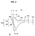
- a protruding height of the sub seal edge portion 62b is lower than a protruding height of the main seal edge portion 62a.
- an interference L2 of the sub seal edge portion 62b is set smaller than an interference L1 of the main seal edge portion 62a in relation to the inner peripheral surface of the outer tube portion 12 or the outer peripheral surface of the inner tube portion 13 of the clutch cylinder shown by a two-dot chain line in Fig. 2 .
- the protruding height of the sub seal edge portion 62b is formed to be lower than the inner peripheral surface of the conventionally shaped seal lip shown by a broken line in Fig. 2 .
- a length Ha0 from the main seal edge portion 62a to the root portion in the anti-hydraulic chamber side space S2 side is shorter than a length Ha in an axial direction from the seal edge portion of the seal lip 101 according to the prior art shown in Fig. 5 which is previously described to the root portion in the anti-hydraulic chamber side space S2 side.
- a length Ha1 in an axial direction between the main seal edge portion 62a and the sub seal edge portion 62b is shorter than a length Ha2 in an axial direction from the sub seal edge portion 62b to the root portion.
- the main seal edge portion 62a exists only a distance Hb1 in an axial direction closer to the hydraulic chamber S1 side than a base portion surface 61a in the hydraulic chamber S1 side of the seal lip 62 in the base portion 61, however, the sub seal edge portion 62b exists only a distance Hb2 in an axial direction closer to an opposite side (the space S2 side) to the hydraulic chamber S1 than the base portion surface 61a.
- An expression Hb1 + Hb2 Ha1 is established.
- the main seal edge portion 62a is formed so that an angle ⁇ 1 of an inclined surface corresponding to the hydraulic chamber S1 side is smaller than an angle ⁇ 1 of an inclined surface corresponding to the opposite side (the space S2 side) to the hydraulic chamber S1 ( ⁇ 1 ⁇ ⁇ 1) under a un-installed state
- the sub seal edge portion 62b is formed so that an angle ⁇ 2 of an inclined surface corresponding to the hydraulic chamber S1 side is smaller than an angle ⁇ 2 of an inclined surface corresponding to the opposite side (the space S2 side) to the hydraulic chamber S1 ( ⁇ 2 ⁇ ⁇ 2) under a un-installed state.
- the hydraulic clutch having the structure mentioned above applies the hydraulic pressure to the hydraulic chamber S1 via the pressure introduction port 14 or releases the hydraulic pressure, the clutch piston 2 displaces in the axial direction within the clutch cylinder 1, and the hydraulic clutch makes the multiple disc clutch 5 carry out a connecting action or a disconnecting action.
- the clutch piston 2 displaces to a downward side in Fig. 1 (the anti-hydraulic chamber side space S2 side) while compressing the return spring 4, and the clutch pressing portion 24 of the clutch piston 2 presses the multiple disc clutch 5 so as to engage frictionally the drive plate 51 and the driven plate 52.
- the multiple disc clutch 5 comes to a connected state, and a driving torque from the drive shaft (not shown) side is transmitted to the driven shaft (not shown) via the clutch cylinder 1, and the drive plate 51, the driven plate 52 and the clutch hub 53 of the multiple disc clutch 5.
- the clutch piston 2 displaces upward in Fig. 1 on the basis of the elongation of the compressed return spring 4 so as to reduce the cubic capacity of the hydraulic chamber S1, and cancels the pressure application to the multiple disc clutch 5.
- the friction engagement between the drive plate 51 and the driven plate 52 of the multiple disc clutch 5 is canceled, and the transmission of the driving torque from the drive shaft to the driven shaft is disconnected.
- the seal lips 62 in its inner and outer peripheries come into close contact with and slides along the inner peripheral surface of the outer tube portion 12 and the outer peripheral surface of the inner tube portion 13 of the clutch cylinder 1. Further, since the main seal edge portion 62a in the hydraulic chamber S1 side and the sub seal edge portion 62b in the anti-hydraulic chamber side space S2 side are formed in the sliding portion, the contact area with the outer tube portion 12 and the inner tube portion 13 of the clutch cylinder 1 becomes smaller. In addition, since the thickness of the seal lip 62 is reduced as a whole in comparison with the conventional shape shown by a broken line in Fig. 2 , the rigidity is lowered.
- the angle ⁇ 1' of the inclined surface in the hydraulic chamber S1 side of the main seal edge portion 62a is approximately equal to the angle ⁇ 1' of the inclined surface in the anti-hydraulic chamber side space S2 side
- the angle ⁇ 2' of the inclined surface in the hydraulic chamber S1 side of the sub seal edge portion 62b is approximately equal to the angle ⁇ 2' of the inclined surface in the anti-hydraulic chamber side space S2 side.
- the contact pressures P1 and P2 of the main seal edge portion 62a and the sub seal edge portion 62b in relation to the inner peripheral surface of the outer tube portion 12 or the outer peripheral surface of the inner tube portion 13 in the clutch cylinder distribute respectively approximately and symmetrically with each other in the hydraulic chamber S1 side and the anti-hydraulic chamber side space S2 side. Therefore, it is possible to effectively reduce the difference between the friction at the stroking time of the clutch piston 2 to the anti-hydraulic chamber side space S2 side (the direction of pressing the multiple disc clutch 5), and the friction at the stroking time of the clutch piston 2 to the hydraulic chamber S1 side (the direction of canceling the pressure application to the multiple disc clutch 5). As a result, it is possible to improve the shift change response of the hydraulic clutch.
- the interference L2 of the sub seal edge portion 62b is set to be smaller than the interference L1 of the main seal edge portion 62a in relation to the inner peripheral surface of the outer tube portion 12 or the outer peripheral surface of the inner tube portion 13 in the clutch cylinder, as shown in Fig. 2 , the deformation of the main seal edge portion 62a can be absorbed by the sub seal edge portion 62b. As a result, the change of the contact load of the main seal edge portion 62a can be suppressed regardless of the change of the hydraulic pressure of the hydraulic chamber S1 applied to the seal lip 62, and the difference in friction mentioned above can be reduced thereby.
- the sub seal edge portion 62b is positioned only the distance Hb2 in the axial direction closer to the anti-hydraulic chamber side space S2 side than the base portion surface 61 a in the hydraulic chamber S1 side of the seal lip 62 in the base portion 61, the deformation of the sub seal edge portion 62b caused by applying the hydraulic pressure to the hydraulic chamber S1 is suppressed. As a result, a deformation suppressing action of the seal lip 62 by the sub seal edge portion 62b is enhanced. Further, since the length Ha0 itself from the main seal edge portion 62a to the root portion in the anti-hydraulic chamber side space S2 side is made shorter than the conventional one shown in Fig. 5 , it is possible to improve the pressure resistance in spite of the matter that the thickness of the seal lip 62 is smaller than the conventional one.
Landscapes
- Engineering & Computer Science (AREA)
- General Engineering & Computer Science (AREA)
- Mechanical Engineering (AREA)
- Hydraulic Clutches, Magnetic Clutches, Fluid Clutches, And Fluid Joints (AREA)
- Sealing With Elastic Sealing Lips (AREA)
Abstract
Description
- The present invention relates to a piston-integrated seal which is used in a hydraulic clutch of an automatic transmission in a vehicle.
-
Fig. 4 shows a hydraulic clutch which employs a conventional piston-integrated seal, andFig. 5 shows an outline structure of the conventional piston-integrated seal. - First of all, in the hydraulic clutch shown in
Fig. 4 ,reference numeral 1 denotes an annular clutch cylinder which rotates together with a drive shaft (not shown),reference numeral 2 denotes a clutch piston which is arranged within theclutch cylinder 1 so as to be movable in an axial direction, and defines a hydraulic chamber S1 between the clutch piston and anend plate portion 11 of theclutch cylinder 1,reference numeral 3 denotes a spring holder which is arranged in a space S2 in an opposite side to the hydraulic chamber S1 as seen from theclutch piston 2 and is locked its inner diameter to aninner tube portion 13 of theclutch cylinder 1,reference numeral 4 denotes a return spring which is interposed between theclutch piston 2 and thespring holder 3 in an appropriately compressed state, andreference numeral 5 denotes a multiple disc clutch constructed by a plurality ofdrive plates 51 which are locked to theclutch cylinder 1 side in a circumferential direction under a movable state in an axial direction, and a plurality of drivenplates 52 which are locked to aclutch hub 53 provided in a driven shaft side in a circumferential direction under a movable state in an axial direction. - This kind of hydraulic clutch is structured such that the
piston 2 displaces in an axial direction within theclutch cylinder 1 by applying a hydraulic pressure to the hydraulic chamber S1 via apressure guide port 14 which is provided in theinner tube portion 13 of theclutch cylinder 1 or releasing the hydraulic pressure, thereby friction fastening thedrive plate 51 and the drivenplate 52 of themultiple disc clutch 5 or canceling the friction fastening so as to carry out a clutch connection and disconnection motion. - A packing such as an O-ring has been conventionally used as a seal means for inner and outer peripheries of the
clutch piston 2, however, theclutch piston 2 is desired to be lowered its friction in order to achieve an improvement of fuel consumption and a reduction of shift shock (a shock generated at the friction fastening time of the clutch). In recent years, a piston-integratedseal 100 havingseal lips seal lips outer tube portion 12 and theinner tube portion 13 of theclutch cylinder 1 while being directed to the hydraulic chamber S1 side. In other words, the piston-integratedseal 100 is integrally formed in theclutch piston 2 by a rubber-like elastic material (a rubber material or a synthetic resin material having a rubber-like elasticity) (refer, for example, to the following patent document 1). - As shown in
Fig. 5 , theseal lip 101 is generally structured such that an angle α of an inclined surface closer to the hydraulic chamber S1 side than the seal edge portion where a contact pressure P (an interference L) in relation to the other sliding surface shown by a two-dot chain line in the drawing is the greatest is larger than an angle β of an inclined surface in an opposite side, and a length Ha in an axial direction from the seal edge portion to the root portion in the opposite side to the hydraulic chamber S1 is comparatively long. -
- Patent Document 1: Japanese Unexamined Patent Publication No.
2001-241467 - Patent Document 2: Japanese Unexamined Patent Publication No.
9-210088 - However, according to the conventional piston-integrated
seal 100, since theseal lip 101 has a directionality, a distribution of the contact pressure P is asymmetrical to each other in both sides of the maximum portion, and there is a tendency that the friction becomes greater at the stroking time of theclutch piston 2 to the clutch fastening canceling side (the hydraulic chamber S1 side) due to an energizing force of thereturn spring 4 when the hydraulic pressure of the hydraulic chamber S1 is released, in comparison with the stroking time of theclutch piston 2 to the clutch fastening side caused by applying the hydraulic pressure to the hydraulic chamber S1. As a result, it is hard to hydraulically control the hydraulic clutch, and there is a risk that a delay in shift change response is generated. - In order to improve the shift change response mentioned above, it is necessary to make a friction difference between the stroke to the clutch fastening canceling side (the hydraulic chamber S1 side) and the stroke to the clutch fastening side (the opposite side to the hydraulic chamber S1) small. Accordingly, reduction of the interference L and the rigidity of the
seal lip 101 has been considered, however, there is a new problem that the pressure resistance and the durability of theseal lip 101 are lowered in this case. - Further, the friction can be reduced by forming a desired number of lubrication grooves in the sliding surface of the seal lip 101 (refer, for example, to the following patent document 2). However, it has been insufficient to reduce the friction difference caused by the directionality of the
seal lip 101. - The present invention is made by taking the above points into consideration, and a technical object of the present invention is to improve a shift change response of a hydraulic clutch by reducing a difference in friction due to a sliding direction caused by a directionality of a seal lip.
- As a means for effectively achieving the technical object mentioned above, a piston-integrated seal according to the invention of a first aspect has a seal lip which is integrally provided in a clutch piston of a hydraulic clutch and is directed to a hydraulic chamber side, the seal lip is structured such that a main seal edge portion in a hydraulic chamber side and a sub seal edge portion in an anti-hydraulic chamber side are formed in a sliding portion in relation to the other sliding surface, and the main seal edge portion and the sub seal edge portion are structured such that an angle of an inclined surface in the hydraulic chamber side is smaller than an angle of an inclined surface in the anti-hydraulic chamber side in a un-installed state, and the angle of the inclined surface in the hydraulic chamber side in relation to the other sliding surface is approximately equal to the angle of the inclined surface in the anti-hydraulic chamber side in an installed state.
- A piston-integrated seal according to the invention of a second aspect is the structure described in the first aspect, wherein an interference of the sub seal edge portion is smaller than an interference of the main seal edge portion.
- A piston-integrated seal according to the invention of a third aspect is the structure described in the first or second aspect, wherein the sub seal edge portion is positioned closer to the anti-hydraulic chamber side than a surface of a base portion in the hydraulic chamber side of the seal lip.
- On the basis of the piston-integrated seal according to the present invention, since the contact area with the other sliding surface is smaller by forming the main seal edge portion in the hydraulic chamber side and the sub seal edge portion in the anti-hydraulic chamber side, in the sliding portion of the seal lip, the friction can be reduced. Further, since the angle of the inclined surface in the hydraulic chamber side in relation to the other sliding surface is approximately equal to the angle of the inclined surface in the anti-hydraulic chamber side in the installed state (the contact state with the other sliding surface), it is possible to reduce the difference between the friction at the stroking time to the hydraulic chamber side and the friction at the stroking time to the anti-hydraulic chamber side. As a result, it is possible to improve the shift change response of the hydraulic clutch.
- Further, according to the structure in which the interference of the sub seal edge portion is smaller than the interference of the main seal edge portion, since the deformation of the main seal edge portion can be absorbed by the sub seal edge portion, change in contact load of the main seal edge portion in relation to the other sliding surface can be suppressed regardless of change of the hydraulic pressure acting on the seal lip. As a result, it is possible to reduce the difference between the friction at the stroking time to the hydraulic chamber side and the friction at the stroking time to the anti-hydraulic chamber side.
- Further, according to the structure in which the sub seal edge portion is positioned closer to the anti-hydraulic chamber side than the surface of the base portion in the hydraulic chamber side of the seal lip, since the deformation of the sub seal edge portion caused by applying the hydraulic pressure is suppressed, a seal lip deformation suppressing action by the sub seal edge portion is enhanced, and it is possible to improve the pressure resistance of the seal lip.
-
-
Fig. 1 is a one-side cross sectional view showing a preferable embodiment of a piston-integrated seal according to the present invention together with a part of a hydraulic clutch by cutting along a plane passing through an axis O; -
Fig. 2 is an explanatory view showing a substantial part of the preferable embodiment of the piston-integrated seal according to the present invention; -
Fig. 3 is an explanatory view showing angles of included surface in a un-installed state and an installed state in the substantial part of the preferable embodiment of the piston-integrated seal according to the present invention; -
Fig. 4 is a one-side cross sectional view showing a conventional piston-integrated seal together with a part of a hydraulic clutch by cutting along a plane passing through an axis O; and -
Fig. 5 is an explanatory view showing a part of the conventional piston-integrated seal. - A description will be given of a preferable embodiment of a piston-integrated seal according to the present invention with reference to the accompanying drawings.
Fig. 1 is a one-side cross sectional view showing the piston-integrated seal according to the embodiment together with a part of a hydraulic clutch,reference numeral 1 denotes a clutch cylinder,reference numeral 2 denotes a clutch piston which is arranged within theclutch cylinder 1 so as to be movable in an axial direction and defines a hydraulic chamber S1 between the clutch piston and theclutch cylinder 1,reference numeral 1 denotes a spring holder which is arranged in a space (hereinafter, refer to as an anti-hydraulic chamber side space) S2 in an opposite side to the hydraulic chamber S1 as seen from thepiston 2 and is locked to aninner tube portion 13 of theclutch cylinder 1 in its inner diameter portion,reference numeral 4 denotes a return spring which is interposed in an appropriately compressed state between theclutch piston 2 and thespring holder 3, andreference numeral 5 denotes a multiple disc clutch. - The
clutch cylinder 1 has anend plate portion 11, and anouter tube portion 12 and aninner tube portion 13 which extend from an outer diameter and an inner diameter of the end plate portion, and is rotated around an axis O together with a drive shaft (not shown). Further, theinner tube portion 13 of theclutch cylinder 1 is provided with apressure introduction port 14 for introducing a hydraulic pressure by an oil (ATF) to the hydraulic chamber S1. - The
clutch piston 2 is a metal press molded product, and has apressure receiving portion 21 which is faced to theend plate portion 11 of theclutch cylinder 1 in an axial direction, anouter tube portion 22 which extends from an outer diameter portion of thepressure receiving portion 21 to the anti-hydraulic chamber side space S2 side and faces to theouter tube portion 12 of theclutch cylinder 1 in a radial direction, and aninner tube portion 23 which extends from an inner diameter portion of thepressure receiving portion 21 to an opposite side to the hydraulic chamber S1 and faces to theinner tube portion 13 of theclutch cylinder 1 in a radial direction. Aclutch pressing portion 24 is formed in a leading end portion of theouter tube portion 22 of theclutch piston 2, and aninward collar portion 25 is formed in a leading end portion of theinner tube portion 13 of theclutch piston 2. - The
return spring 4 is structured such as to always energize theclutch piston 2 in a direction of reducing a cubic capacity of the hydraulic chamber S1 and is constructed by a coil spring. A plurality ofreturn springs 4 are arranged at predetermined intervals in a circumferential direction. - The
multiple disc clutch 5 is structured such that a plurality ofdrive plates 51 and a plurality of drivenplates 52 are arranged alternately in an axial direction. Thedrive plates 51 are locked to the outer tube portion of theclutch cylinder 1 in a circumferential direction in a state in which thedrive plates 51 can move in an axial direction, and the drivenplates 52 are locked to aclutch hub 53 provided in a driven shaft side (not shown) in a circumferential direction in a state in which the driven shaft can move in an axial direction. - A piston-integrated
seal 6 made of a rubber-like elastic material (a rubber material or a synthetic resin material having a rubber-like elasticity) is integrally provided in theclutch piston 2. The piston-integratedseal 6 has abase portion 61 which extends so as to cover an outer peripheral surface of theouter tube portion 22, a surface in the hydraulic chamber S1 side of thepressure receiving portion 21, an inner peripheral surface of theinner tube portion 23 and theinward collar portion 25 in theclutch piston 2, andseal lips pressure receiving portion 21 and an inner diameter of theinward collar portion 25 and are formed so as to extend from thebase portion 61 to the hydraulic chamber S1 side. Theseal 62 lip in the outer peripheral side is slidably brought into close contact with the inner peripheral surface of theouter tube portion 12 in theclutch cylinder 1, and theseal lip 62 in the inner peripheral side is slidably brought into close contact with the outer peripheral surface of theinner tube portion 13 in theclutch cylinder 1. - Further, a plurality of
projections 63 are formed at uniform intervals in a circumferential direction in a portion which is bonded to thepressure receiving portion 21 of theclutch piston 2, in thebase portion 61 of the piston-integratedseal 6. Theprojections 63 prevent occlusion of the hydraulic chamber S1 by the close contact of thebase portion 61 with theend plate portion 11 of theclutch cylinder 1 when theclutch piston 2 moves to its top dead center position. - The
seal lip 62 is structured, as shown inFig. 2 in an enlarged manner, such that a mainseal edge portion 62a in the hydraulic chamber S1 side and a subseal edge portion 62b in the anti-hydraulic chamber side space S2 side are formed in a sliding portion with an inner peripheral surface of theouter tube portion 12 of theclutch cylinder 1 or an outer peripheral surface of theinner tube portion 13. - Describing in detail, a protruding height of the sub
seal edge portion 62b is lower than a protruding height of the mainseal edge portion 62a. As a result, an interference L2 of the subseal edge portion 62b is set smaller than an interference L1 of the mainseal edge portion 62a in relation to the inner peripheral surface of theouter tube portion 12 or the outer peripheral surface of theinner tube portion 13 of the clutch cylinder shown by a two-dot chain line inFig. 2 . Further, the protruding height of the subseal edge portion 62b is formed to be lower than the inner peripheral surface of the conventionally shaped seal lip shown by a broken line inFig. 2 . - As shown in
Fig. 2 , a length Ha0 from the mainseal edge portion 62a to the root portion in the anti-hydraulic chamber side space S2 side is shorter than a length Ha in an axial direction from the seal edge portion of theseal lip 101 according to the prior art shown inFig. 5 which is previously described to the root portion in the anti-hydraulic chamber side space S2 side. Further, a length Ha1 in an axial direction between the mainseal edge portion 62a and the subseal edge portion 62b is shorter than a length Ha2 in an axial direction from the subseal edge portion 62b to the root portion. - The main
seal edge portion 62a exists only a distance Hb1 in an axial direction closer to the hydraulic chamber S1 side than abase portion surface 61a in the hydraulic chamber S1 side of theseal lip 62 in thebase portion 61, however, the subseal edge portion 62b exists only a distance Hb2 in an axial direction closer to an opposite side (the space S2 side) to the hydraulic chamber S1 than thebase portion surface 61a. An expression Hb1 + Hb2 = Ha1 is established. - Further, as shown in
Fig. 3 , the mainseal edge portion 62a is formed so that an angle α1 of an inclined surface corresponding to the hydraulic chamber S1 side is smaller than an angle β1 of an inclined surface corresponding to the opposite side (the space S2 side) to the hydraulic chamber S1 (α1 < β1) under a un-installed state, and the subseal edge portion 62b is formed so that an angle α2 of an inclined surface corresponding to the hydraulic chamber S1 side is smaller than an angle β2 of an inclined surface corresponding to the opposite side (the space S2 side) to the hydraulic chamber S1 (α2 < β2) under a un-installed state. Further, an expression α1 > α2 and an expression β1 > β2 are established. - As a result, since the
seal lip 62 is exposed to a bending deformation around its root under the installed state, an angle α1' which the inclined surface in the hydraulic chamber S1 side of the mainseal edge portion 62a forms in relation to the inner peripheral surface of theouter tube portion 12 or the outer peripheral surface of theinner tube portion 13 in the clutch cylinder is increased somewhat in relation to α1, and an angle β1' which the inclined surface in the anti-hydraulic chamber side space S2 side forms is inversely reduced somewhat in relation to β1. As a result, an expression α1' ≅ β1' is established. Same applies to the subseal edge portion 62b, an angle α2' which the inclined surface in the hydraulic chamber S1 side forms is increased somewhat in relation to α2 under the installed state, and an angle β2' which the inclined surface in the anti-hydraulic chamber side space S2 side forms is inversely reduced somewhat in relation to β2. As a result, an expression α2' ≅ β2' is established. - Since the hydraulic clutch having the structure mentioned above applies the hydraulic pressure to the hydraulic chamber S1 via the
pressure introduction port 14 or releases the hydraulic pressure, theclutch piston 2 displaces in the axial direction within theclutch cylinder 1, and the hydraulic clutch makes themultiple disc clutch 5 carry out a connecting action or a disconnecting action. - More specifically, in the case that the hydraulic chamber S1 is pressurized by feeding the oil (ATF), the
clutch piston 2 displaces to a downward side inFig. 1 (the anti-hydraulic chamber side space S2 side) while compressing thereturn spring 4, and the clutch pressingportion 24 of theclutch piston 2 presses themultiple disc clutch 5 so as to engage frictionally thedrive plate 51 and the drivenplate 52. As a result, themultiple disc clutch 5 comes to a connected state, and a driving torque from the drive shaft (not shown) side is transmitted to the driven shaft (not shown) via theclutch cylinder 1, and thedrive plate 51, the drivenplate 52 and theclutch hub 53 of themultiple disc clutch 5. - Further, in the case that the hydraulic pressure of the hydraulic chamber S1 is released from the connected state, the
clutch piston 2 displaces upward inFig. 1 on the basis of the elongation of the compressedreturn spring 4 so as to reduce the cubic capacity of the hydraulic chamber S1, and cancels the pressure application to themultiple disc clutch 5. As a result, the friction engagement between thedrive plate 51 and the drivenplate 52 of themultiple disc clutch 5 is canceled, and the transmission of the driving torque from the drive shaft to the driven shaft is disconnected. - In the displacement of the
clutch piston 2 mentioned above, in the piston-integratedseal 6 integrally provided in theclutch piston 2, theseal lips 62 in its inner and outer peripheries come into close contact with and slides along the inner peripheral surface of theouter tube portion 12 and the outer peripheral surface of theinner tube portion 13 of theclutch cylinder 1. Further, since the mainseal edge portion 62a in the hydraulic chamber S1 side and the subseal edge portion 62b in the anti-hydraulic chamber side space S2 side are formed in the sliding portion, the contact area with theouter tube portion 12 and theinner tube portion 13 of theclutch cylinder 1 becomes smaller. In addition, since the thickness of theseal lip 62 is reduced as a whole in comparison with the conventional shape shown by a broken line inFig. 2 , the rigidity is lowered. As a result, the contact pressures P1 and P2 by the mainseal edge portion 62a and the subseal edge portion 62b shown inFig. 3 become smaller as a whole in comparison with the conventional contact pressure shown by the broken line. Further, since the portion between both theseal edge portions - Further, in a state in which the
seal lip 62 comes into contact with the inner peripheral surface of theouter tube portion 12 or the outer peripheral surface of theinner tube portion 13 in the clutch cylinder as shown by [installed state] inFig. 3 , the angle α1' of the inclined surface in the hydraulic chamber S1 side of the mainseal edge portion 62a is approximately equal to the angle β1' of the inclined surface in the anti-hydraulic chamber side space S2 side, and the angle α2' of the inclined surface in the hydraulic chamber S1 side of the subseal edge portion 62b is approximately equal to the angle β2' of the inclined surface in the anti-hydraulic chamber side space S2 side. As a result, the contact pressures P1 and P2 of the mainseal edge portion 62a and the subseal edge portion 62b in relation to the inner peripheral surface of theouter tube portion 12 or the outer peripheral surface of theinner tube portion 13 in the clutch cylinder distribute respectively approximately and symmetrically with each other in the hydraulic chamber S1 side and the anti-hydraulic chamber side space S2 side. Therefore, it is possible to effectively reduce the difference between the friction at the stroking time of theclutch piston 2 to the anti-hydraulic chamber side space S2 side (the direction of pressing the multiple disc clutch 5), and the friction at the stroking time of theclutch piston 2 to the hydraulic chamber S1 side (the direction of canceling the pressure application to the multiple disc clutch 5). As a result, it is possible to improve the shift change response of the hydraulic clutch. - Further, since the interference L2 of the sub
seal edge portion 62b is set to be smaller than the interference L1 of the mainseal edge portion 62a in relation to the inner peripheral surface of theouter tube portion 12 or the outer peripheral surface of theinner tube portion 13 in the clutch cylinder, as shown inFig. 2 , the deformation of the mainseal edge portion 62a can be absorbed by the subseal edge portion 62b. As a result, the change of the contact load of the mainseal edge portion 62a can be suppressed regardless of the change of the hydraulic pressure of the hydraulic chamber S1 applied to theseal lip 62, and the difference in friction mentioned above can be reduced thereby. - Further, since the sub
seal edge portion 62b is positioned only the distance Hb2 in the axial direction closer to the anti-hydraulic chamber side space S2 side than thebase portion surface 61 a in the hydraulic chamber S1 side of theseal lip 62 in thebase portion 61, the deformation of the subseal edge portion 62b caused by applying the hydraulic pressure to the hydraulic chamber S1 is suppressed. As a result, a deformation suppressing action of theseal lip 62 by the subseal edge portion 62b is enhanced. Further, since the length Ha0 itself from the mainseal edge portion 62a to the root portion in the anti-hydraulic chamber side space S2 side is made shorter than the conventional one shown inFig. 5 , it is possible to improve the pressure resistance in spite of the matter that the thickness of theseal lip 62 is smaller than the conventional one. -
- 1 clutch cylinder
- 2 clutch piston
- 6 seal
- 61 base portion
- 62 seal lip
- 62a main seal edge portion
- 62b sub seal edge portion
- S1 hydraulic chamber
- S2 anti-hydraulic chamber side space
Claims (3)
- A piston-integrated seal comprising:a seal lip which is integrally provided in a clutch piston of a hydraulic clutch and is directed to a hydraulic chamber side,wherein the seal lip is structured such that a main seal edge portion in a hydraulic chamber side and a sub seal edge portion in an anti-hydraulic chamber side are formed in a sliding portion in relation to the other sliding surface, andwherein the main seal edge portion and the sub seal edge portion are structured such that an angle of an inclined surface in the hydraulic chamber side is smaller than an angle of an inclined surface in the anti-hydraulic chamber side in a un-installed state, and the angle of the inclined surface in the hydraulic chamber side in relation to the other sliding surface is approximately equal to the angle of the inclined surface in the anti-hydraulic chamber side in an installed state.
- The piston-integrated seal according to claim 1, wherein an interference of the sub seal edge portion is smaller than an interference of the main seal edge portion.
- The piston-integrated seal according to claim 1 or 2, wherein the sub seal edge portion is positioned closer to the anti-hydraulic chamber side than a surface of a base portion in the hydraulic chamber side of the seal lip.
Applications Claiming Priority (2)
| Application Number | Priority Date | Filing Date | Title |
|---|---|---|---|
| JP2013109509A JP6117000B2 (en) | 2013-05-24 | 2013-05-24 | Piston integrated seal |
| PCT/JP2013/079187 WO2014188616A1 (en) | 2013-05-24 | 2013-10-29 | Piston-integrated seal |
Publications (3)
| Publication Number | Publication Date |
|---|---|
| EP3006762A1 true EP3006762A1 (en) | 2016-04-13 |
| EP3006762A4 EP3006762A4 (en) | 2016-04-20 |
| EP3006762B1 EP3006762B1 (en) | 2018-07-04 |
Family
ID=51933195
Family Applications (1)
| Application Number | Title | Priority Date | Filing Date |
|---|---|---|---|
| EP13885064.9A Active EP3006762B1 (en) | 2013-05-24 | 2013-10-29 | Piston-integrated seal |
Country Status (6)
| Country | Link |
|---|---|
| US (1) | US9482292B2 (en) |
| EP (1) | EP3006762B1 (en) |
| JP (1) | JP6117000B2 (en) |
| KR (1) | KR102080668B1 (en) |
| CN (1) | CN105247234B (en) |
| WO (1) | WO2014188616A1 (en) |
Cited By (1)
| Publication number | Priority date | Publication date | Assignee | Title |
|---|---|---|---|---|
| US11608138B2 (en) | 2019-09-11 | 2023-03-21 | Aktiebolaget Skf | Sealing device in particular for shock-absorber stems |
Families Citing this family (4)
| Publication number | Priority date | Publication date | Assignee | Title |
|---|---|---|---|---|
| JP2019203524A (en) * | 2018-05-21 | 2019-11-28 | Nok株式会社 | Clutch piston |
| JP2020076478A (en) * | 2018-11-09 | 2020-05-21 | Nok株式会社 | Piston seal for automatic transmission |
| US11592108B2 (en) * | 2019-09-19 | 2023-02-28 | Aktiebolaget Skf | Seal having a lip optimized for low temperature applications |
| FR3129998B1 (en) * | 2021-12-03 | 2024-03-15 | Valeo Embrayages | Wet clutch |
Family Cites Families (21)
| Publication number | Priority date | Publication date | Assignee | Title |
|---|---|---|---|---|
| DE3411824A1 (en) * | 1984-03-30 | 1985-10-10 | FAG Kugelfischer Georg Schäfer KGaA, 8720 Schweinfurt | PISTON UNIT |
| US5172793A (en) * | 1990-06-21 | 1992-12-22 | Allied-Signal Inc. | Vehicle brake with brake cylinder bore insert |
| JP3613833B2 (en) * | 1994-11-04 | 2005-01-26 | Nok株式会社 | Reciprocating sealing device |
| JPH09210088A (en) | 1996-01-29 | 1997-08-12 | Nok Corp | Sealing device |
| JPH09292031A (en) * | 1996-04-24 | 1997-11-11 | Nok Corp | Sealing device for reciprocating motion |
| JP2918494B2 (en) * | 1996-06-12 | 1999-07-12 | 倉敷化工株式会社 | Lip type seal |
| DE19707652C2 (en) * | 1997-02-26 | 1999-12-30 | Freudenberg Carl Fa | Sealing ring |
| JPH1151197A (en) * | 1997-07-31 | 1999-02-23 | Koyo Seiko Co Ltd | Clutch piston of fluid type transmission |
| DE19839502C2 (en) * | 1998-08-29 | 2001-06-07 | Freudenberg Carl Fa | Sealing ring |
| US6039160A (en) * | 1998-08-31 | 2000-03-21 | General Motors Corporation | Friction torque transmitter with a one-way actuator |
| JP3380785B2 (en) | 2000-02-29 | 2003-02-24 | 三菱電線工業株式会社 | Cancel plate |
| DE10222933A1 (en) * | 2002-05-24 | 2003-12-04 | Zf Sachs Ag | Hydraulically actuated clutch device with at least one bleedable or flushable hydraulic slave cylinder and corresponding hydraulic slave cylinder arrangement |
| JP3793746B2 (en) * | 2002-07-02 | 2006-07-05 | 株式会社ジェイテクト | Sliding member and sealing device |
| CN100417848C (en) * | 2002-09-09 | 2008-09-10 | Nok株式会社 | Sealing means |
| US20040251107A1 (en) * | 2003-03-25 | 2004-12-16 | Sefcik Michael C. | Clutch housing with multi-function hydraulic sleeve |
| WO2005090813A1 (en) * | 2004-03-19 | 2005-09-29 | Nok Corporation | Piston |
| JP2007239826A (en) * | 2006-03-07 | 2007-09-20 | Dainatsukusu:Kk | Seal structure of canceler of wet type clutch |
| JP4649500B2 (en) * | 2008-07-31 | 2011-03-09 | トヨタ自動車株式会社 | Sealing device |
| JP5484093B2 (en) * | 2010-01-22 | 2014-05-07 | 光洋シーリングテクノ株式会社 | Clutch piston for fluid transmission |
| WO2012024470A1 (en) * | 2010-08-18 | 2012-02-23 | Skf Usa Inc. | Seal with pressure-actuatable sealing bead |
| JP5756392B2 (en) * | 2011-11-01 | 2015-07-29 | カヤバ工業株式会社 | Sealing device and shock absorber provided with the sealing device |
-
2013
- 2013-05-24 JP JP2013109509A patent/JP6117000B2/en active Active
- 2013-10-29 CN CN201380076807.7A patent/CN105247234B/en active Active
- 2013-10-29 US US14/892,305 patent/US9482292B2/en active Active
- 2013-10-29 EP EP13885064.9A patent/EP3006762B1/en active Active
- 2013-10-29 KR KR1020157034793A patent/KR102080668B1/en active Active
- 2013-10-29 WO PCT/JP2013/079187 patent/WO2014188616A1/en not_active Ceased
Cited By (1)
| Publication number | Priority date | Publication date | Assignee | Title |
|---|---|---|---|---|
| US11608138B2 (en) | 2019-09-11 | 2023-03-21 | Aktiebolaget Skf | Sealing device in particular for shock-absorber stems |
Also Published As
| Publication number | Publication date |
|---|---|
| WO2014188616A1 (en) | 2014-11-27 |
| EP3006762A4 (en) | 2016-04-20 |
| CN105247234A (en) | 2016-01-13 |
| US20160091033A1 (en) | 2016-03-31 |
| CN105247234B (en) | 2018-08-31 |
| KR102080668B1 (en) | 2020-02-24 |
| JP2014228089A (en) | 2014-12-08 |
| US9482292B2 (en) | 2016-11-01 |
| KR20160011646A (en) | 2016-02-01 |
| EP3006762B1 (en) | 2018-07-04 |
| JP6117000B2 (en) | 2017-04-19 |
Similar Documents
| Publication | Publication Date | Title |
|---|---|---|
| EP3006762B1 (en) | Piston-integrated seal | |
| US20090235815A1 (en) | Piston with built-in seal | |
| CN104736873B (en) | Piston-cylinder unit for hydraulic systems | |
| KR20110127605A (en) | Fluid pressure equipment | |
| US5937985A (en) | Retaining ring in a hydraulically actuated friction element assembly for an automatic transmission | |
| US8607689B2 (en) | Seal member for a hydraulic braking system | |
| US9447878B2 (en) | Piston seal assembly | |
| JP5574090B2 (en) | Reciprocating seal ring | |
| US10100881B2 (en) | Clutch seal | |
| US9677625B2 (en) | Concentric slave cylinder including one-way clutch | |
| US20090038906A1 (en) | Seal integral type piston | |
| US20070278747A1 (en) | Sealing Device | |
| US20080245225A1 (en) | Piston for automatic transmission | |
| KR101155649B1 (en) | Friction element | |
| JP2006242311A (en) | Sealing device of hydraulic actuator for automatic transmission | |
| US20080023893A1 (en) | Hermetically Sealing Device | |
| JP2012215188A (en) | Sealing structure | |
| KR101208885B1 (en) | Rubber Ring for Clutch Piston of Multi-plate Clutch System of Auto Transmission | |
| US20220178390A1 (en) | Hydraulic actuator sealing device | |
| JP5070016B2 (en) | Cancel plate for fluid transmission | |
| US20140339041A1 (en) | Integrated leaf spring and seal retention | |
| KR102262105B1 (en) | Clutch device for automatic transmission | |
| JP4576204B2 (en) | Clutch cylinder for fluid transmission | |
| JP2006144901A (en) | Reciprocation seal | |
| US20220316540A1 (en) | Disc Brake Device |
Legal Events
| Date | Code | Title | Description |
|---|---|---|---|
| PUAI | Public reference made under article 153(3) epc to a published international application that has entered the european phase |
Free format text: ORIGINAL CODE: 0009012 |
|
| 17P | Request for examination filed |
Effective date: 20151130 |
|
| AK | Designated contracting states |
Kind code of ref document: A1 Designated state(s): AL AT BE BG CH CY CZ DE DK EE ES FI FR GB GR HR HU IE IS IT LI LT LU LV MC MK MT NL NO PL PT RO RS SE SI SK SM TR |
|
| AX | Request for extension of the european patent |
Extension state: BA ME |
|
| A4 | Supplementary search report drawn up and despatched |
Effective date: 20160321 |
|
| RIC1 | Information provided on ipc code assigned before grant |
Ipc: F16J 15/32 20060101ALI20160315BHEP Ipc: F16D 25/12 20060101AFI20160315BHEP |
|
| DAX | Request for extension of the european patent (deleted) | ||
| 17Q | First examination report despatched |
Effective date: 20170223 |
|
| GRAP | Despatch of communication of intention to grant a patent |
Free format text: ORIGINAL CODE: EPIDOSNIGR1 |
|
| INTG | Intention to grant announced |
Effective date: 20180126 |
|
| GRAS | Grant fee paid |
Free format text: ORIGINAL CODE: EPIDOSNIGR3 |
|
| GRAA | (expected) grant |
Free format text: ORIGINAL CODE: 0009210 |
|
| AK | Designated contracting states |
Kind code of ref document: B1 Designated state(s): AL AT BE BG CH CY CZ DE DK EE ES FI FR GB GR HR HU IE IS IT LI LT LU LV MC MK MT NL NO PL PT RO RS SE SI SK SM TR |
|
| REG | Reference to a national code |
Ref country code: GB Ref legal event code: FG4D |
|
| REG | Reference to a national code |
Ref country code: CH Ref legal event code: EP |
|
| REG | Reference to a national code |
Ref country code: AT Ref legal event code: REF Ref document number: 1014849 Country of ref document: AT Kind code of ref document: T Effective date: 20180715 |
|
| REG | Reference to a national code |
Ref country code: IE Ref legal event code: FG4D |
|
| REG | Reference to a national code |
Ref country code: DE Ref legal event code: R096 Ref document number: 602013039924 Country of ref document: DE |
|
| REG | Reference to a national code |
Ref country code: FR Ref legal event code: PLFP Year of fee payment: 6 |
|
| REG | Reference to a national code |
Ref country code: NL Ref legal event code: MP Effective date: 20180704 |
|
| REG | Reference to a national code |
Ref country code: LT Ref legal event code: MG4D |
|
| REG | Reference to a national code |
Ref country code: AT Ref legal event code: MK05 Ref document number: 1014849 Country of ref document: AT Kind code of ref document: T Effective date: 20180704 |
|
| PG25 | Lapsed in a contracting state [announced via postgrant information from national office to epo] |
Ref country code: NL Free format text: LAPSE BECAUSE OF FAILURE TO SUBMIT A TRANSLATION OF THE DESCRIPTION OR TO PAY THE FEE WITHIN THE PRESCRIBED TIME-LIMIT Effective date: 20180704 |
|
| PG25 | Lapsed in a contracting state [announced via postgrant information from national office to epo] |
Ref country code: SE Free format text: LAPSE BECAUSE OF FAILURE TO SUBMIT A TRANSLATION OF THE DESCRIPTION OR TO PAY THE FEE WITHIN THE PRESCRIBED TIME-LIMIT Effective date: 20180704 Ref country code: BG Free format text: LAPSE BECAUSE OF FAILURE TO SUBMIT A TRANSLATION OF THE DESCRIPTION OR TO PAY THE FEE WITHIN THE PRESCRIBED TIME-LIMIT Effective date: 20181004 Ref country code: GR Free format text: LAPSE BECAUSE OF FAILURE TO SUBMIT A TRANSLATION OF THE DESCRIPTION OR TO PAY THE FEE WITHIN THE PRESCRIBED TIME-LIMIT Effective date: 20181005 Ref country code: IS Free format text: LAPSE BECAUSE OF FAILURE TO SUBMIT A TRANSLATION OF THE DESCRIPTION OR TO PAY THE FEE WITHIN THE PRESCRIBED TIME-LIMIT Effective date: 20181104 Ref country code: NO Free format text: LAPSE BECAUSE OF FAILURE TO SUBMIT A TRANSLATION OF THE DESCRIPTION OR TO PAY THE FEE WITHIN THE PRESCRIBED TIME-LIMIT Effective date: 20181004 Ref country code: PL Free format text: LAPSE BECAUSE OF FAILURE TO SUBMIT A TRANSLATION OF THE DESCRIPTION OR TO PAY THE FEE WITHIN THE PRESCRIBED TIME-LIMIT Effective date: 20180704 Ref country code: AT Free format text: LAPSE BECAUSE OF FAILURE TO SUBMIT A TRANSLATION OF THE DESCRIPTION OR TO PAY THE FEE WITHIN THE PRESCRIBED TIME-LIMIT Effective date: 20180704 Ref country code: FI Free format text: LAPSE BECAUSE OF FAILURE TO SUBMIT A TRANSLATION OF THE DESCRIPTION OR TO PAY THE FEE WITHIN THE PRESCRIBED TIME-LIMIT Effective date: 20180704 Ref country code: RS Free format text: LAPSE BECAUSE OF FAILURE TO SUBMIT A TRANSLATION OF THE DESCRIPTION OR TO PAY THE FEE WITHIN THE PRESCRIBED TIME-LIMIT Effective date: 20180704 Ref country code: LT Free format text: LAPSE BECAUSE OF FAILURE TO SUBMIT A TRANSLATION OF THE DESCRIPTION OR TO PAY THE FEE WITHIN THE PRESCRIBED TIME-LIMIT Effective date: 20180704 Ref country code: CZ Free format text: LAPSE BECAUSE OF FAILURE TO SUBMIT A TRANSLATION OF THE DESCRIPTION OR TO PAY THE FEE WITHIN THE PRESCRIBED TIME-LIMIT Effective date: 20180704 |
|
| PG25 | Lapsed in a contracting state [announced via postgrant information from national office to epo] |
Ref country code: LV Free format text: LAPSE BECAUSE OF FAILURE TO SUBMIT A TRANSLATION OF THE DESCRIPTION OR TO PAY THE FEE WITHIN THE PRESCRIBED TIME-LIMIT Effective date: 20180704 Ref country code: ES Free format text: LAPSE BECAUSE OF FAILURE TO SUBMIT A TRANSLATION OF THE DESCRIPTION OR TO PAY THE FEE WITHIN THE PRESCRIBED TIME-LIMIT Effective date: 20180704 Ref country code: AL Free format text: LAPSE BECAUSE OF FAILURE TO SUBMIT A TRANSLATION OF THE DESCRIPTION OR TO PAY THE FEE WITHIN THE PRESCRIBED TIME-LIMIT Effective date: 20180704 Ref country code: HR Free format text: LAPSE BECAUSE OF FAILURE TO SUBMIT A TRANSLATION OF THE DESCRIPTION OR TO PAY THE FEE WITHIN THE PRESCRIBED TIME-LIMIT Effective date: 20180704 |
|
| REG | Reference to a national code |
Ref country code: DE Ref legal event code: R097 Ref document number: 602013039924 Country of ref document: DE |
|
| PG25 | Lapsed in a contracting state [announced via postgrant information from national office to epo] |
Ref country code: RO Free format text: LAPSE BECAUSE OF FAILURE TO SUBMIT A TRANSLATION OF THE DESCRIPTION OR TO PAY THE FEE WITHIN THE PRESCRIBED TIME-LIMIT Effective date: 20180704 Ref country code: IT Free format text: LAPSE BECAUSE OF FAILURE TO SUBMIT A TRANSLATION OF THE DESCRIPTION OR TO PAY THE FEE WITHIN THE PRESCRIBED TIME-LIMIT Effective date: 20180704 Ref country code: EE Free format text: LAPSE BECAUSE OF FAILURE TO SUBMIT A TRANSLATION OF THE DESCRIPTION OR TO PAY THE FEE WITHIN THE PRESCRIBED TIME-LIMIT Effective date: 20180704 |
|
| PLBE | No opposition filed within time limit |
Free format text: ORIGINAL CODE: 0009261 |
|
| STAA | Information on the status of an ep patent application or granted ep patent |
Free format text: STATUS: NO OPPOSITION FILED WITHIN TIME LIMIT |
|
| PG25 | Lapsed in a contracting state [announced via postgrant information from national office to epo] |
Ref country code: SK Free format text: LAPSE BECAUSE OF FAILURE TO SUBMIT A TRANSLATION OF THE DESCRIPTION OR TO PAY THE FEE WITHIN THE PRESCRIBED TIME-LIMIT Effective date: 20180704 Ref country code: DK Free format text: LAPSE BECAUSE OF FAILURE TO SUBMIT A TRANSLATION OF THE DESCRIPTION OR TO PAY THE FEE WITHIN THE PRESCRIBED TIME-LIMIT Effective date: 20180704 Ref country code: SM Free format text: LAPSE BECAUSE OF FAILURE TO SUBMIT A TRANSLATION OF THE DESCRIPTION OR TO PAY THE FEE WITHIN THE PRESCRIBED TIME-LIMIT Effective date: 20180704 |
|
| REG | Reference to a national code |
Ref country code: CH Ref legal event code: PL |
|
| 26N | No opposition filed |
Effective date: 20190405 |
|
| REG | Reference to a national code |
Ref country code: BE Ref legal event code: MM Effective date: 20181031 |
|
| PG25 | Lapsed in a contracting state [announced via postgrant information from national office to epo] |
Ref country code: MC Free format text: LAPSE BECAUSE OF FAILURE TO SUBMIT A TRANSLATION OF THE DESCRIPTION OR TO PAY THE FEE WITHIN THE PRESCRIBED TIME-LIMIT Effective date: 20180704 Ref country code: LU Free format text: LAPSE BECAUSE OF NON-PAYMENT OF DUE FEES Effective date: 20181029 |
|
| REG | Reference to a national code |
Ref country code: IE Ref legal event code: MM4A |
|
| PG25 | Lapsed in a contracting state [announced via postgrant information from national office to epo] |
Ref country code: LI Free format text: LAPSE BECAUSE OF NON-PAYMENT OF DUE FEES Effective date: 20181031 Ref country code: SI Free format text: LAPSE BECAUSE OF FAILURE TO SUBMIT A TRANSLATION OF THE DESCRIPTION OR TO PAY THE FEE WITHIN THE PRESCRIBED TIME-LIMIT Effective date: 20180704 Ref country code: CH Free format text: LAPSE BECAUSE OF NON-PAYMENT OF DUE FEES Effective date: 20181031 Ref country code: BE Free format text: LAPSE BECAUSE OF NON-PAYMENT OF DUE FEES Effective date: 20181031 |
|
| PG25 | Lapsed in a contracting state [announced via postgrant information from national office to epo] |
Ref country code: IE Free format text: LAPSE BECAUSE OF NON-PAYMENT OF DUE FEES Effective date: 20181029 |
|
| PG25 | Lapsed in a contracting state [announced via postgrant information from national office to epo] |
Ref country code: MT Free format text: LAPSE BECAUSE OF NON-PAYMENT OF DUE FEES Effective date: 20181029 |
|
| PG25 | Lapsed in a contracting state [announced via postgrant information from national office to epo] |
Ref country code: TR Free format text: LAPSE BECAUSE OF FAILURE TO SUBMIT A TRANSLATION OF THE DESCRIPTION OR TO PAY THE FEE WITHIN THE PRESCRIBED TIME-LIMIT Effective date: 20180704 |
|
| PG25 | Lapsed in a contracting state [announced via postgrant information from national office to epo] |
Ref country code: PT Free format text: LAPSE BECAUSE OF FAILURE TO SUBMIT A TRANSLATION OF THE DESCRIPTION OR TO PAY THE FEE WITHIN THE PRESCRIBED TIME-LIMIT Effective date: 20180704 |
|
| PG25 | Lapsed in a contracting state [announced via postgrant information from national office to epo] |
Ref country code: CY Free format text: LAPSE BECAUSE OF FAILURE TO SUBMIT A TRANSLATION OF THE DESCRIPTION OR TO PAY THE FEE WITHIN THE PRESCRIBED TIME-LIMIT Effective date: 20180704 Ref country code: MK Free format text: LAPSE BECAUSE OF NON-PAYMENT OF DUE FEES Effective date: 20180704 Ref country code: HU Free format text: LAPSE BECAUSE OF FAILURE TO SUBMIT A TRANSLATION OF THE DESCRIPTION OR TO PAY THE FEE WITHIN THE PRESCRIBED TIME-LIMIT; INVALID AB INITIO Effective date: 20131029 |
|
| PGFP | Annual fee paid to national office [announced via postgrant information from national office to epo] |
Ref country code: GB Payment date: 20250904 Year of fee payment: 13 |
|
| PGFP | Annual fee paid to national office [announced via postgrant information from national office to epo] |
Ref country code: FR Payment date: 20250908 Year of fee payment: 13 |
|
| PGFP | Annual fee paid to national office [announced via postgrant information from national office to epo] |
Ref country code: DE Payment date: 20250902 Year of fee payment: 13 |