EP3006673A1 - Procédé et dispositif permettant de mesurer l'usure d'interverrouillage d'aubes carénées - Google Patents
Procédé et dispositif permettant de mesurer l'usure d'interverrouillage d'aubes carénées Download PDFInfo
- Publication number
- EP3006673A1 EP3006673A1 EP14187914.8A EP14187914A EP3006673A1 EP 3006673 A1 EP3006673 A1 EP 3006673A1 EP 14187914 A EP14187914 A EP 14187914A EP 3006673 A1 EP3006673 A1 EP 3006673A1
- Authority
- EP
- European Patent Office
- Prior art keywords
- blades
- datum
- parameter
- pair
- interlock
- Prior art date
- Legal status (The legal status is an assumption and is not a legal conclusion. Google has not performed a legal analysis and makes no representation as to the accuracy of the status listed.)
- Withdrawn
Links
Images


Classifications
-
- F—MECHANICAL ENGINEERING; LIGHTING; HEATING; WEAPONS; BLASTING
- F01—MACHINES OR ENGINES IN GENERAL; ENGINE PLANTS IN GENERAL; STEAM ENGINES
- F01D—NON-POSITIVE DISPLACEMENT MACHINES OR ENGINES, e.g. STEAM TURBINES
- F01D5/00—Blades; Blade-carrying members; Heating, heat-insulating, cooling or antivibration means on the blades or the members
- F01D5/12—Blades
- F01D5/22—Blade-to-blade connections, e.g. for damping vibrations
- F01D5/225—Blade-to-blade connections, e.g. for damping vibrations by shrouding
-
- F—MECHANICAL ENGINEERING; LIGHTING; HEATING; WEAPONS; BLASTING
- F05—INDEXING SCHEMES RELATING TO ENGINES OR PUMPS IN VARIOUS SUBCLASSES OF CLASSES F01-F04
- F05D—INDEXING SCHEME FOR ASPECTS RELATING TO NON-POSITIVE-DISPLACEMENT MACHINES OR ENGINES, GAS-TURBINES OR JET-PROPULSION PLANTS
- F05D2230/00—Manufacture
- F05D2230/72—Maintenance
-
- F—MECHANICAL ENGINEERING; LIGHTING; HEATING; WEAPONS; BLASTING
- F05—INDEXING SCHEMES RELATING TO ENGINES OR PUMPS IN VARIOUS SUBCLASSES OF CLASSES F01-F04
- F05D—INDEXING SCHEME FOR ASPECTS RELATING TO NON-POSITIVE-DISPLACEMENT MACHINES OR ENGINES, GAS-TURBINES OR JET-PROPULSION PLANTS
- F05D2240/00—Components
- F05D2240/20—Rotors
- F05D2240/30—Characteristics of rotor blades, i.e. of any element transforming dynamic fluid energy to or from rotational energy and being attached to a rotor
- F05D2240/307—Characteristics of rotor blades, i.e. of any element transforming dynamic fluid energy to or from rotational energy and being attached to a rotor related to the tip of a rotor blade
-
- F—MECHANICAL ENGINEERING; LIGHTING; HEATING; WEAPONS; BLASTING
- F05—INDEXING SCHEMES RELATING TO ENGINES OR PUMPS IN VARIOUS SUBCLASSES OF CLASSES F01-F04
- F05D—INDEXING SCHEME FOR ASPECTS RELATING TO NON-POSITIVE-DISPLACEMENT MACHINES OR ENGINES, GAS-TURBINES OR JET-PROPULSION PLANTS
- F05D2260/00—Function
- F05D2260/30—Retaining components in desired mutual position
- F05D2260/36—Retaining components in desired mutual position by a form fit connection, e.g. by interlocking
-
- F—MECHANICAL ENGINEERING; LIGHTING; HEATING; WEAPONS; BLASTING
- F05—INDEXING SCHEMES RELATING TO ENGINES OR PUMPS IN VARIOUS SUBCLASSES OF CLASSES F01-F04
- F05D—INDEXING SCHEME FOR ASPECTS RELATING TO NON-POSITIVE-DISPLACEMENT MACHINES OR ENGINES, GAS-TURBINES OR JET-PROPULSION PLANTS
- F05D2260/00—Function
- F05D2260/80—Diagnostics
-
- F—MECHANICAL ENGINEERING; LIGHTING; HEATING; WEAPONS; BLASTING
- F05—INDEXING SCHEMES RELATING TO ENGINES OR PUMPS IN VARIOUS SUBCLASSES OF CLASSES F01-F04
- F05D—INDEXING SCHEME FOR ASPECTS RELATING TO NON-POSITIVE-DISPLACEMENT MACHINES OR ENGINES, GAS-TURBINES OR JET-PROPULSION PLANTS
- F05D2260/00—Function
- F05D2260/82—Forecasts
- F05D2260/821—Parameter estimation or prediction
-
- F—MECHANICAL ENGINEERING; LIGHTING; HEATING; WEAPONS; BLASTING
- F05—INDEXING SCHEMES RELATING TO ENGINES OR PUMPS IN VARIOUS SUBCLASSES OF CLASSES F01-F04
- F05D—INDEXING SCHEME FOR ASPECTS RELATING TO NON-POSITIVE-DISPLACEMENT MACHINES OR ENGINES, GAS-TURBINES OR JET-PROPULSION PLANTS
- F05D2260/00—Function
- F05D2260/83—Testing, e.g. methods, components or tools therefor
Definitions
- the present invention relates to a method of measuring the wear on abutting surfaces of blades of a gas turbine for example and scheduling maintenance.
- the present invention also relates to an arrangement of a pair of blades.
- Blades for example of a turbine section of a gas turbine engine, which have interlocked shrouded tips are subjected to vibrations which are damped by the use of a sliding surface contact between the interlock faces. Damping is controlled by the level of force between each pair of interlock faces. The contact and sliding of these interlock faces results in wear of the surfaces. As wear increases, the interlock surface coating thickness decreases, or in the case of no coating, the parent material is reduced. The force on the interlock faces is provided by twist in the blades during operation and as surface material is worn away the level of twist reduces and hence the force also reduces. As the level of force on the interlock faces reduces the damping affect reduces.
- One objective of the present invention is to determine wear of interlock surfaces. Another objective is to maintain the interlock surfaces or replace the blades. Another objective is to prevent or reduce vibrations between adjacent blades and/or the blade assembly. Another objective is to improve performance of the blade assembly and/or the engine. Another objective is to maintain a minimum level of vibration damping. Another objective is to increase the life of the blades by repairing the interlock surfaces. Another objective is to design blades with sufficient life and minimum damping performance to last between scheduled maintenance events for the turbine engine. Another objective is to reduce or eliminate unscheduled engine shutdown caused by loss of vibration damping caused by wear of the interlock surfaces of the blade. Another objective is to provide the operator with a more controlled and predictable servicing or maintenance scheduling of the engine. Another objective is to reduce inventory by virtue of preventing unscheduled replacement of blades.
- each blade comprises a root portion, an aerofoil and a shroud
- each shroud defines at least one boss having an interlock surface and the interlock faces of the adjacent blades are arranged to contact one another in sliding frictional contact to damp relative movement between the adjacent blades
- each boss further defines a datum surface, the datum surfaces are arranged parallel to one another.
- Each boss is specifically provided for the purpose of measuring a dimension to determine the amount of wear of the interlock surfaces.
- the dimension can be a distance from one datum surface to the other datum surface or an angle between the planes of the datum surfaces.
- the angular measurement can be suitable for determining uneven wear between the interlock surfaces. Both the distance and angular measurements can be taken before operating the blades and after operating the blade and the difference at these two measurements gives wear characteristics. It is even possible to measure the change in angle of one or both datum surfaces to give the degree of twist or untwist of the blade caused by wear. From any one of these measurement it is possible to correlate or calculate the force between the interlock surfaces at any given time.
- the datum surfaces may be parallel to the interlock surfaces. Alternatively, the datum surfaces may be non-parallel to the interlock surfaces.
- the datum surfaces may be arranged such that a line normal to the datum surfaces passes through the interlock surfaces.
- Each blade may comprise a radially outwardly extending fin and all of the datum surfaces are located on one side of the fin.
- the blade(s) may comprise two fins which are parallel to one another, the datum surfaces are located outside either fin.
- a method of maintaining a pair of circumferentially adjacent blades comprises the steps of assembling the blades adjacent one another, measuring a parameter between the two datum surfaces to obtain a datum parameter, operating the blades, measuring the parameter between the two datum surfaces to obtain a second parameter, and calculating the difference between the datum parameter and the second parameter to give a wear value for the pair of blades and where the wear value is less than a first predetermined value, scheduling a maintenance event or the wear value is greater than the first predetermined value, servicing at least one of the blades.
- the parameter may be a dimension.
- the dimension is the distance the datum surfaces are apart.
- a single measurement can be taken for example at the centre of each datum surface.
- the measurement point(s) on each surface are preferably at the same locations each measurement taken.
- a number of measurements can be taken for example three or four at spaced apart locations on each surface.
- any uneven wear can be determined by virtue of different changes of the dimension across the whole surface.
- wear two or more measurements are taken across each datum surface, the relative angle of the two datum surfaces can be determined again by simple trigonometry.
- the parameter may be an angle.
- the angular measurement can be made to determine whether uneven or non-parallel wear has taken place.
- the angular measurement can also ensure that the datum surfaces are parallel or approximately parallel on unworn blades.
- the angular measurement can be made to verify any calculation of the relative angle of the datum surfaces calculated from the multiple dimensions measured.
- the wear value may be any one of a simple dimension or may have a coefficient applied to it.
- the coefficient may be derived from any one or more in-service characteristics from the group comprising number of engine starts, the number of accelerations and decelerations of rotational speeds, the amount of time at certain engine conditions and the vibration history.
- servicing or maintenance of at least one of the blades comprises at least one of the group comprising replacing a coating on the interlock surface, refurbishing the parent material of the interlock surface, for example by welding or laser deposition of substrate, or replacement of one or more blades.
- a method of maintaining an annular array of blades having pairs of circumferentially adjacent blades as described above, the steps of measuring a parameter between the two datum surfaces to obtain a datum parameter is completed on at least two pairs of blades, and measuring the parameter between the two datum surfaces to obtain a second parameter is completed on at least two pairs of blades, calculating the difference between the datum parameter and the second parameter to give the wear value for annular array blades, and where the wear value is less than a first predetermined value, scheduling a maintenance event or the wear value is greater than the first predetermined value, servicing all of the blades in the array of blades.
- the step of averaging the calculated difference between the datum parameter and the second parameter to give an average wear value for each pair of blades may include comparing the average wear value to the predetermined value.
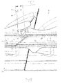
- FIG. 1 shows an example of a twin-shaft gas turbine engine 10 in a sectional view and generally arranged about a longitudinal axis 20.
- the gas turbine engine 10 comprises, in flow series, an inlet 12, a compressor section 14, a combustor section 16 and a turbine section 18 which are generally arranged in flow series and generally in the direction of the longitudinal or rotational axis 20.
- the gas turbine engine 10 further comprises a shaft 22 which is rotatable about the rotational axis 20 and which extends longitudinally through the gas turbine engine 10.
- the shaft 22 drivingly connects a high-pressure turbine 17 of the turbine section 18 to the compressor section 12..
- the turbine section 18 also includes a low-pressure turbine 19 drivingly connected to a load (not shown) via a second shaft 23 of the twin-shaft arrangement.
- the combustor section 16 comprises an annular array of combustor units 16 only one of which is shown.
- air 24 which is taken in through the air inlet 12 is compressed by the compressor section 14 and delivered to the combustion section or unit 16.
- the combustor unit 16 comprises a burner plenum 26, a pre-chamber 29, a combustion chamber 28 defined by a double walled can 27 and at least one burner 30 fixed to each combustion chamber 28.
- the pre-chamber 29, the combustion chamber 28 and the burner 30 are located inside the burner plenum 26.
- the compressed air 31 passing through the compressor 12 enters a diffuser 32 and is discharged from the diffuser 32 into the burner plenum 26 from where a portion of the air enters the burner 30 and is mixed with a gaseous and/or liquid fuel.
- the air/fuel mixture is then burned and the resulting combustion gas 34 or working gas from the combustion chamber is channelled via a transition duct 35 to the turbine section 18.
- the turbine section 18 comprises a number of blade carrying rotor discs 36 attached to the shaft 22.
- both the high and low pressure turbines 19,17 have two discs 36 each carrying an annular array of turbine blades 38.
- the number of blade carrying rotor discs could be different, i.e. only one disc or more than two rotor discs.
- guiding vanes may be fixed to a stator 42 of the gas turbine engine 10 and are disposed between the turbine blade stages 38. Between the exit of the combustion chamber 28 and the leading turbine blades 38 inlet guiding vanes 44 are provided.
- the combustion gas 34 from the combustion chamber 28 enters the turbine section 18 and drives the turbine blades 38 which in turn rotates the shaft 22 to drive the compressor section 12.
- the guiding vanes 44 serve to optimise the angle of the combustion or working gas on to the turbine blades 38.
- the compressor section 12 comprises an axial series of guide vane stages 46 and rotor blade stages 48. After passing through the high-pressure turbine 17, the hot working gas flow is directed into the low-pressure turbine 19 which drives the load via the second shaft 23.
- the low-pressure turbine 19 is generally arranged similarly to the high-pressure turbine 17 as is well known.
- upstream and downstream refer to the flow direction of the airflow and/or working gas flow through the engine unless otherwise stated.
- forward and rearward refer to the general flow of gas through the engine.
- axial, radial and circumferential are made with reference to the rotational axis 20 of the engine unless otherwise stated.
- FIG. 2 is a view of a tip 49 of a conventional blade 51 looking in a generally circumferential direction. The circumferential direction is shown by arrow A.
- Each blade 51 has a root portion 50 (see FIG.1 ), an inner platform 52 (see FIG.1 ), an aerofoil 54 and a shroud 56.
- the aerofoil 54 has a suction surface 62 and a pressure surface 64 which meet at a leading edge 58 and a trailing edge 60.
- the shroud 56 has radially outwardly extending first and second fins 66, 68 which along with the surrounding casing seal against over tip leakage of hot working gases.
- the first fins 66 and second fins 68 align with and abut to respective first and second fins on circumferentially adjacent blades to form a circumferential ring of first and second fins at certain blade twist conditions dependant on rotational speed, temperature and blade wear.
- the second fins 68 have widened end surfaces 70, 72 and immediately adjacent blades have opposing ends surfaces 70, 72 contacting or abutting one another. These widened end surfaces 70, 72 are not parallel to each other because they are optimised for manufacturability and the minimum use of material. The widening end surface 70, 72 is provided to distribute the contact force/area. This contact area will wear during operation and deform over time.
- the shroud 56 has shaped circumferential ends 74 and 75, only one of which is shown, having three planar portions 78, 70, 76 which abut or have a minimum gap between respective planar portions on the adjacent blade shroud. These three planar portions are generally aligned with the radial direction and are angled relative to the rotational axis 20 in an orthogonal direction when in situ. The three planar portions are angled to one another such that their surfaces form a Z-shape when viewed radially inwardly. The middle planar portion is the widened end surface 70, 72.
- This type of shroud arrangement can be referred to as an interlocked shrouded tip. Where two blades 80 abut one another at their respective circumferential end 74 and circumferential end 75, the joint is referred to as an interlock joint.
- the interlock joint comprises the three planar portions 78, 70, 76.
- blades may be designed with the interlock joint having only planar portions 70.
- Planar portions 76 and 78 need not be incorporated as the function of these is normally to form a gas path and can be non-functional in terms of blade damping.
- the blades and therefore shrouds are subjected to vibrations which are damped by the action and friction of the surface contact between the interlock faces or planar portions 78, 70, 76. Damping is controlled by the level of force between each pair of interlock faces. The contact and sliding of these interlock faces results in wear of the surfaces. As wear increases, the interlock surface coating thickness decreases, or in the case of no coating, the parent material is reduced.
- the force on the interlock faces, particularly the widened end surface 70, 72 is provided by twist in the blades during operation and as surface material is worn away the level of twist reduces and hence the force also reduces. As the level of force on the interlock faces reduces the damping effectiveness reduces. This wear can result in a loss of damping which is unacceptable and may cause resonances to occur which may damage the blades.
- the present invention described now utilises a new feature on each blade tip so that each pair of adjacent and contacting blades provide a pair of parallel surfaces across the interlock surfaces of adjacent blades. These parallel surfaces are referred to as datum surfaces and can be used to directly measure the wear of the interlock surfaces between adjacent blades without the requirement of disassembling the blades from the disc.
- the present invention is now described with reference to a method of assessing the wear of the interlock surfaces and is essentially a method of maintaining the damping characteristics of a pair of blades and therefore the annular array of blades.
- the dimension between parallel datum surfaces across the interlock surfaces is recorded and after a period in-service a subsequent measurement is compared with the first build to assess the amount of wear. As the wear increases, the blades further twist to take up the effective wear amount or gap. The initial parallel datum surfaces also twist relative to each other but remain parallel due to the twist being equal between the blade pairs.
- FIGS. 3-5 the same reference numerals have been used to denote the same features as described with reference to FIGS. 1 and 2 .
- FIG. 3 is a view looking in a radially inward direction on the tips 49 of parts of two circumferentially adjacent blades 80 configured in accordance with the present invention.
- the pair of blades 80 is intended to be located within the turbine of the gas turbine engine of FIG.1 and as a number of pairs in the array of blades 37 and/or 38.
- Each tip 49 or shroud 56 of each blade 80 of the pair of blades comprises a boss 84, 90 which define a datum surface 88, 92 and an interlock surface 86, 94 respectively.
- the interlock surfaces 86, 94 are abutting or contacting one another and the datum surfaces 88, 92 are parallel one another and in this first embodiment the datum surfaces 88, 92 are also parallel to the interlock surfaces 86, 94.
- the pair of parallel datum surfaces 88, 92 enable direct measurement of the dimension across the interlock surfaces 86, 94. In this embodiment a line normal to the interlock surfaces 86, 94 passes through and is normal to the datum surfaces 88, 92.
- any two circumferentially adjacent blades 80 can be the pair of blades 80 herein referred to.
- the interlock joint comprises the three planar portions 78, 76 and the interlock surfaces 86, 94.
- Each blade 80 comprises a radially outwardly extending fin 68 and the datum surfaces 88, 92 are located on one side of the fin 68.
- the blade 80 shown here comprises two fins, a first fin 66 which is axially forward of a second fin 68, which are generally parallel to one another.
- the datum surfaces 88, 92 are located axially rearward of the second fin 68 although the datum surfaces 88, 92 could be axially forward of the first fin 66 to enable ease of access.
- the term 'outside' can be used to denote that the datum surfaces 88, 92 are not between the two fins 66, 68.
- the datum surfaces 88, 92 could be either side of the fin.
- FIG.3 the interlock surfaces 86, 94 are shown without wear and in a newly assembled condition.
- the interlock surfaces 86, 94 are in full contact with one another.
- the dimension A is measured across the two bosses 84, 90 from one datum surface to the other.
- the other planar portions 78, 76 of opposing blade's circumferential ends 74 can be in contact although due to tolerances only one of the planar portions 78 are shown in contact with one another.
- FIG. 4 is the same view as FIG.3 , looking in a radially inward direction on the tips 49 or shrouds 56 of parts of two circumferentially adjacent blades 80 in accordance with the present invention.
- the interlock surfaces 86, 94 are abutting one another and the datum surfaces 88, 92 are parallel one another and in this second embodiment the datum surfaces 88, 92 are not parallel to the interlock surfaces 86, 94.
- the interlock surfaces 86, 94 are shown without wear and in a newly assembled condition.
- the interlock surfaces 86, 94 are in contact with one another.
- the dimension B is measured across the two bosses 84, 90 from one datum surface to the other.
- the other planar portions 78, 76 of opposing blade's circumferential ends 74 can be in contact although due to tolerances only one of the planar portions 78 of adjacent blades are in contact with one another.
- FIG.5 is a view looking in a radially inward direction on the tips 49 or shrouds 56 of parts of a pair of circumferentially adjacent blades 80 in accordance with the present invention and as shown in FIG.4 , but here the interlock surfaces 86, 94 are in a worn condition.
- the dimension 'C' is measured across the two bosses 84, 90 from one datum surface 88, 92 to the other.
- the dimension C is smaller than the dimension B and therefore is an indicator of wear.
- the change in twist due to the wearing of the interlock surfaces 86, 94 can be seen by the change in angle of the datum surfaces 88, 92.
- the wearing of the interlock surfaces 86, 94 and subsequent twist of the blades 80 can also be seen in the misalignment of the shrouds 56 of adjacent blades 80.
- the misalignment of the shrouds 56 is indicated by the dimension D.
- the direction of twist of the blades is indicated by the arrows 98 and which can be seen to be in the anticlockwise sense as viewed in FIG.5 ; that is radially inwardly.
- the direction and angular change ⁇ of rotation of adjacent blades 80 is approximately the same. This does not matter whether both interlock surfaces 86, 94 wear equally or whether one of the interlock surfaces 86, 94 wears preferentially to the other.
- the amount of wear of one or both the interlock surfaces 86, 94 can be calculated by subtracting the worn dimension C from the pre-wear dimension B.
- the pre-wear dimension B can be referred to as the datum dimension.
- This direct measurement of wear is termed a wear value.
- Another parameter of wear may be determined and used to calculate the wear value.
- FIG.6 uneven or non-parallel wear of the interlock surfaces 86, 94 has occurred and there is now an angular difference or change in angle ⁇ between the datum faces 88, 92 which can be measured.
- the angle ⁇ between the datum faces 88, 92 can be measured directly as an angle or may be calculated from the change in distance between reference point pairs 102A, 102B and 104A, 104B.
- the change in distance is the difference between the datum measurement and a later worn measurement.
- any difference between the two reference point pairs 102A, 102B and 104A, 104B will indicate uneven or non-parallel wear.
- the angle ⁇ between the datum faces 88, 92 may be calculated by simple trigonometry where the distance between reference points 102A, 104A and 102B, 104B respectively on the same datum surface 88, 92 are known. Further pairs of reference points may be used to identify uneven wear in an orthogonal direction, radial for example, rather than in the plane of the figure as shown in FIG.6 .
- the present invention also relates to a method of maintaining the blades 80 and in particular a method of maintaining the damping characteristics of pairs of circumferentially adjacent blades 80.
- the method involves assembling the blades 80 adjacent one another on the rotor disc and to form the annular array of blades 37, 38.
- An initial measurement of the dimension A or B is made depending on the configuration of the bosses 84, 90.
- the measurement A or B is between the two datum surfaces 88, 92 to obtain the datum dimension A or B.
- This dimension is recorded for each blade pair around the array of blades 37, 38. Note that to measure all dimensions A, B or C of each blade pair will involve two measurements of each blade's two datum surface which are located at opposite circumferential ends 74, 75 of the shroud 49. Alternatively, only a certain number of blade pairs can be measured if they are representative of the wear characteristics of all the blades 80 in the array of blades 37, 38.
- the engine is serviced or inspected for any number of reasons.
- the dimension between the two datum surfaces 88, 92 is measured to obtain the second or wear dimension C.
- a wear value is calculated from the difference between the datum dimension and the second dimension.
- the wear value can be a simple value for the difference between dimensions B and C in, for example, millimetres or fractions of millimetres.
- the wear value can be based on a coefficient derived from the in-service life activity between obtaining the datum dimension and the second dimension and multiplied by the simple wear value. For example, wear might be dependent on or influenced by a number of factors or in-service characteristics including the number of engine starts, the number of accelerations and decelerations of rotational speeds, the amount of time at certain engine conditions and importantly the vibration history.
- the present invention can be extended to measuring the dimensions, whether dimensions A, B, C or the angle ⁇ or the distance between reference points 102A, 104A and 102B, 104B, more than once during the life of the blades.
- the wear rates can be characterised the wear rates and either predict from theory or ascertain empirically the life from any pair or set of datum and second measurements where the interval and operation experience between measurements is known.
- Accelerations and decelerations will increase and decrease centrifugal forces on the blades and force them to twist and untwist, thereby loading and unloading the interlock surfaces 86, 94 and causing them to move across each other and wear more than at steady state operating conditions with little or no vibration. Further, certain engine operating points can give rise to different levels of vibration. As vibration manifests itself as relative movement of the two contacting interlock surfaces 86, 94, the vibration characteristics of the blade pair and/or annular array of blade 37, 38 has a marked effect on the wear characteristics of the blade and therefore it's damping characteristics.
- the vibration history can include modes of vibration, amplitude in any direction, duration of any vibratory event including phase, excitation force, oscillations in flow or speed etc.
- the wear value dependent on the wear value, whether simple or with a coefficient applied, then either maintenance is carried out immediately or a maintenance/service event is scheduled to be carried out later. This later or future service event may be coordinated with the normal service intervals for other component of the gas turbine engine.
- the wear value dependent on the wear value, whether simple or with a coefficient applied, where it is greater than a predetermined value then either maintenance is carried out or a maintenance event is scheduled later to be carried out.
- the wear value can be compared to the in-service life expectancy, whether the life expectancy is calculated or empirically determined, and the amount of remaining life can be calculated to establish a future maintenance/service event.
- the coefficient can be determined via an algorithm derived from engine operational parameters and its measured in-service performance.
- the method includes scheduling a future maintenance event or where the wear value is greater than the first predetermined value immediately service at least one of the blades.
- This method of maintenance can be carried out on a blade by blade approach and certain blades or blade pairs can be maintained on an individual basis.
- this method can be extended to maintaining an annular assembly of pairs of circumferentially adjacent blades where at least two dimensions between the two datum surfaces 88, 92 of at least two blade pairs are measured to obtain a set of datum dimensions A or B representative of the blade assembly or annular array of blades.
- the at least two dimensions C between the now relatively worn two datum surfaces 88, 92 are measured to obtain a set of second dimension C representative of the blade assembly.
- the method of maintenance of the annular array of blades on the rotor assembly can be averaged from the calculated difference between the datum dimension A, B and the second or worn dimension C to give an average wear value for the array of blades 37, 38 and the this average wear value is compared the predetermined value.
- the future scheduled or immediate maintenance or servicing event can first include remeasurement and assessment of the wear value. Again if the wear value is greater than a predetermined value then at least one of the blades, pair of blades or the annular array of blades is serviced or maintained.
- the maintenance or servicing can involve replacing a coating on the interlock surface, refurbishing the parent material of the interlock surface for example by welding or laser deposition of substrate, or replacement of one or more blades 80.
- FIG.7 which is an enlarged view of the interlock joint, a coating 100 is shown applied to the interlock surface 94.
- the coating 100 can be a material that preferentially wears so that maintenance of the blade involves reapplying the coating rather than replacing the blade or thickening the substrate.
- both interlock surfaces 86, 94 can have a coating applied so that neither blade requires replacement and only the coating reapplied once worn.
- the coating 100 can be a softer material to the blade's base material so that the coating is sacrificial.
- the coating material can be selected to maximise or optimise frictional characteristics to tailor specific damping requirements.
- the coating may be applied to only one of the interlock surfaces 86, 94 or to both interlock surfaces 86, 94 and in the latter case the coatings can be different to preferentially wear one coating more than the other.
- a maintenance event is scheduled.
- This maintenance event can be part of an existing maintenance scheduling such as an engine service or overhaul.
- the first predetermined value can be set such that at the time of measuring the dimension C, the remaining life of the interlock surfaces 86, 94 is sufficient to last until a future scheduled maintenance event for the engine.
- the dimensions A, B and C may be measured using known instruments such as callipers, dial gauges, vernier scales or micrometer and can be analogue, digital or electronic. It is also possible to measure the dimensions A, B and C as well as the pairs of reference points 102A, 102B and 104A, 104B via a coordinate measuring machine having a touch sensitive probe to measure the datum faces and in the event of non-parallel wear the angle ⁇ .
- the term 'parameter' is used to denote a dimension, e.g. A, B, C or reference point pairs, or the angle whether measured directly or calculated from another measured value.
- the dimensions A, B and C are used interchangeably for a single measurement point of the datum surfaces or whether numerous measurement points (for multiple pairs of reference points) are made. Dimensions A and B are intended to be relative to the two embodiments shown and described with reference to FIG.3 and FIG.4 respectively.
- the method of maintaining the annular array of blades 38 may be extended so that two or more sets of datum and second parameters are measured. A first set of measurements and resulting wear values is taken. Here the datum parameter measurement can be of unworn blades and the second parameter measurement are then in a worn condition. A second set of datum and second parameters can then be measured. Here the datum parameter measurement can be the original unworn datum measurement.
- the datum parameter measurement can be a re-datum measurement and can even be the first second measurement.
- the rate of wear of the interlock surfaces can be calculated.
- the measurements here can be related to the contact pressure between the two abutting surfaces 86, 94.
- the target value or lower limit of contact pressure will depend on the specific application in particular, the size of the blade, the design of the shroud and the maintenance intervals as well as the excitation levels, just to mention a few factors. Where a minimum pressure is achieved a preferable level of damping will exist.
Landscapes
- Engineering & Computer Science (AREA)
- Mechanical Engineering (AREA)
- General Engineering & Computer Science (AREA)
- Turbine Rotor Nozzle Sealing (AREA)
Priority Applications (2)
| Application Number | Priority Date | Filing Date | Title |
|---|---|---|---|
| EP14187914.8A EP3006673A1 (fr) | 2014-10-07 | 2014-10-07 | Procédé et dispositif permettant de mesurer l'usure d'interverrouillage d'aubes carénées |
| PCT/EP2015/072570 WO2016055328A1 (fr) | 2014-10-07 | 2015-09-30 | Procédé et agencement de mesure de l'usure de verrouillage d'aubes à talon |
Applications Claiming Priority (1)
| Application Number | Priority Date | Filing Date | Title |
|---|---|---|---|
| EP14187914.8A EP3006673A1 (fr) | 2014-10-07 | 2014-10-07 | Procédé et dispositif permettant de mesurer l'usure d'interverrouillage d'aubes carénées |
Publications (1)
| Publication Number | Publication Date |
|---|---|
| EP3006673A1 true EP3006673A1 (fr) | 2016-04-13 |
Family
ID=51687852
Family Applications (1)
| Application Number | Title | Priority Date | Filing Date |
|---|---|---|---|
| EP14187914.8A Withdrawn EP3006673A1 (fr) | 2014-10-07 | 2014-10-07 | Procédé et dispositif permettant de mesurer l'usure d'interverrouillage d'aubes carénées |
Country Status (2)
| Country | Link |
|---|---|
| EP (1) | EP3006673A1 (fr) |
| WO (1) | WO2016055328A1 (fr) |
Cited By (2)
| Publication number | Priority date | Publication date | Assignee | Title |
|---|---|---|---|---|
| FR3077600A1 (fr) * | 2018-02-08 | 2019-08-09 | Safran Aircraft Engines | Aube de turbomachine d'aeronef |
| US10914180B2 (en) | 2018-01-29 | 2021-02-09 | MTU Aero Engines AG | Shroud segment for disposition on a blade of a turbomachine, and blade |
Families Citing this family (1)
| Publication number | Priority date | Publication date | Assignee | Title |
|---|---|---|---|---|
| FR3125085A1 (fr) * | 2021-07-12 | 2023-01-13 | Safran Aircraft Engines | Aube de turbomachine |
Citations (5)
| Publication number | Priority date | Publication date | Assignee | Title |
|---|---|---|---|---|
| CA1317789C (fr) * | 1989-06-19 | 1993-05-18 | Leonard William Davidson | Outil de jaugeage d'usure |
| US20040124231A1 (en) * | 1999-06-29 | 2004-07-01 | Hasz Wayne Charles | Method for coating a substrate |
| US20100135775A1 (en) * | 2008-12-01 | 2010-06-03 | Alstom Technology Ltd | Turbomachine, especially steam turbine |
| EP2236753A1 (fr) * | 2009-03-24 | 2010-10-06 | Siemens Aktiengesellschaft | Ensemble d'aubes pour turbomachine |
| EP2249151A1 (fr) * | 2009-04-30 | 2010-11-10 | AVIO S.p.A. | Procédé et dispositif de mesure de l'usure d'une aube |
-
2014
- 2014-10-07 EP EP14187914.8A patent/EP3006673A1/fr not_active Withdrawn
-
2015
- 2015-09-30 WO PCT/EP2015/072570 patent/WO2016055328A1/fr active Application Filing
Patent Citations (5)
| Publication number | Priority date | Publication date | Assignee | Title |
|---|---|---|---|---|
| CA1317789C (fr) * | 1989-06-19 | 1993-05-18 | Leonard William Davidson | Outil de jaugeage d'usure |
| US20040124231A1 (en) * | 1999-06-29 | 2004-07-01 | Hasz Wayne Charles | Method for coating a substrate |
| US20100135775A1 (en) * | 2008-12-01 | 2010-06-03 | Alstom Technology Ltd | Turbomachine, especially steam turbine |
| EP2236753A1 (fr) * | 2009-03-24 | 2010-10-06 | Siemens Aktiengesellschaft | Ensemble d'aubes pour turbomachine |
| EP2249151A1 (fr) * | 2009-04-30 | 2010-11-10 | AVIO S.p.A. | Procédé et dispositif de mesure de l'usure d'une aube |
Cited By (5)
| Publication number | Priority date | Publication date | Assignee | Title |
|---|---|---|---|---|
| US10914180B2 (en) | 2018-01-29 | 2021-02-09 | MTU Aero Engines AG | Shroud segment for disposition on a blade of a turbomachine, and blade |
| FR3077600A1 (fr) * | 2018-02-08 | 2019-08-09 | Safran Aircraft Engines | Aube de turbomachine d'aeronef |
| WO2019154734A1 (fr) * | 2018-02-08 | 2019-08-15 | Safran Aircraft Engines | Aube de turbomachine d'aeronef |
| CN111742115A (zh) * | 2018-02-08 | 2020-10-02 | 赛峰飞机发动机公司 | 用于飞行器涡轮发动机的叶片 |
| US11746662B2 (en) | 2018-02-08 | 2023-09-05 | Safran Aircraft Engines | Vane for an aircraft turbomachine |
Also Published As
| Publication number | Publication date |
|---|---|
| WO2016055328A1 (fr) | 2016-04-14 |
Similar Documents
| Publication | Publication Date | Title |
|---|---|---|
| US8230726B2 (en) | Methods, systems and apparatus relating to tip clearance calculations in turbine engines | |
| US9822647B2 (en) | High chord bucket with dual part span shrouds and curved dovetail | |
| US20100068050A1 (en) | Gas turbine vane attachment | |
| EP2990660B1 (fr) | Dispositif de contrôle d'usure d'un moteur à turbine à gaz | |
| US9322280B2 (en) | Method of measuring turbine blade tip erosion | |
| US10633983B2 (en) | Airfoil tip geometry to reduce blade wear in gas turbine engines | |
| EP3176377A1 (fr) | Système pour déterminer l'usure et composant de moteur à turbine associé | |
| EP3006673A1 (fr) | Procédé et dispositif permettant de mesurer l'usure d'interverrouillage d'aubes carénées | |
| US20160108737A1 (en) | Blade system, and corresponding method of manufacturing a blade system | |
| US10358933B2 (en) | Turbine tip clearance control method and system | |
| US10385865B2 (en) | Airfoil tip geometry to reduce blade wear in gas turbine engines | |
| Mishra et al. | Investigation of LP turbine blade failure in a low bypass turbofan engine | |
| US20180073399A1 (en) | Turbine blade assembly arrangement and corresponding assembly tool | |
| US10557349B2 (en) | Method and system for repairing a turbomachine | |
| Dinc et al. | Fundamental design issues of brush seals for industrial applications | |
| EP3901412B1 (fr) | Configurations d'enveloppe d'amortisseur | |
| CN110691891A (zh) | 燃气轮机发动机转子盘保持组件 | |
| US9297271B2 (en) | Turbine blade monitoring arrangement and method of manufacturing | |
| US8689634B2 (en) | Systems and methods for mode shape identification | |
| Khani et al. | Towards development of a Diagnostic and Prognostic tool for civil aero-engine component degradation | |
| JP2021147999A (ja) | ガスタービン圧縮機 | |
| Miranda Rivera | Assembly fit-up issue: investigation of a first stage high pressure gas turbine rotor | |
| Boeller et al. | An Introduction Into the Clearance Management of Ansaldo GT36 From Development to Validation | |
| Smed et al. | 501F compressor development program | |
| Navrotsky et al. | Continued enhancement of SGT-600 gas turbine design and maintenance |
Legal Events
| Date | Code | Title | Description |
|---|---|---|---|
| PUAI | Public reference made under article 153(3) epc to a published international application that has entered the european phase |
Free format text: ORIGINAL CODE: 0009012 |
|
| AK | Designated contracting states |
Kind code of ref document: A1 Designated state(s): AL AT BE BG CH CY CZ DE DK EE ES FI FR GB GR HR HU IE IS IT LI LT LU LV MC MK MT NL NO PL PT RO RS SE SI SK SM TR |
|
| AX | Request for extension of the european patent |
Extension state: BA ME |
|
| STAA | Information on the status of an ep patent application or granted ep patent |
Free format text: STATUS: THE APPLICATION HAS BEEN PUBLISHED |
|
| STAA | Information on the status of an ep patent application or granted ep patent |
Free format text: STATUS: THE APPLICATION IS DEEMED TO BE WITHDRAWN |
|
| 18D | Application deemed to be withdrawn |
Effective date: 20161014 |