EP3006398A1 - Carbon nanotube sheet and production method for carbon nanotube sheet - Google Patents
Carbon nanotube sheet and production method for carbon nanotube sheet Download PDFInfo
- Publication number
- EP3006398A1 EP3006398A1 EP14808111.0A EP14808111A EP3006398A1 EP 3006398 A1 EP3006398 A1 EP 3006398A1 EP 14808111 A EP14808111 A EP 14808111A EP 3006398 A1 EP3006398 A1 EP 3006398A1
- Authority
- EP
- European Patent Office
- Prior art keywords
- sheet
- carbon nanotubes
- carbon nanotube
- production method
- layer
- Prior art date
- Legal status (The legal status is an assumption and is not a legal conclusion. Google has not performed a legal analysis and makes no representation as to the accuracy of the status listed.)
- Withdrawn
Links
- OKTJSMMVPCPJKN-UHFFFAOYSA-N Carbon Chemical compound [C] OKTJSMMVPCPJKN-UHFFFAOYSA-N 0.000 title claims abstract description 239
- 239000002041 carbon nanotube Substances 0.000 title claims abstract description 238
- 229910021393 carbon nanotube Inorganic materials 0.000 title claims abstract description 238
- 238000004519 manufacturing process Methods 0.000 title claims description 74
- 238000010000 carbonizing Methods 0.000 claims description 24
- 239000002131 composite material Substances 0.000 claims description 20
- 238000003825 pressing Methods 0.000 claims description 7
- 239000011261 inert gas Substances 0.000 claims description 5
- 238000010438 heat treatment Methods 0.000 claims description 4
- 238000005452 bending Methods 0.000 claims description 3
- 239000010410 layer Substances 0.000 description 101
- 239000000758 substrate Substances 0.000 description 62
- 239000003351 stiffener Substances 0.000 description 14
- 230000000717 retained effect Effects 0.000 description 8
- 239000007789 gas Substances 0.000 description 7
- IJGRMHOSHXDMSA-UHFFFAOYSA-N Atomic nitrogen Chemical compound N#N IJGRMHOSHXDMSA-UHFFFAOYSA-N 0.000 description 6
- 229910001873 dinitrogen Inorganic materials 0.000 description 6
- 229920005989 resin Polymers 0.000 description 6
- 239000011347 resin Substances 0.000 description 6
- 230000000694 effects Effects 0.000 description 5
- 229920001187 thermosetting polymer Polymers 0.000 description 5
- 238000000034 method Methods 0.000 description 4
- 239000002356 single layer Substances 0.000 description 4
- 238000010586 diagram Methods 0.000 description 3
- 239000000835 fiber Substances 0.000 description 3
- XKRFYHLGVUSROY-UHFFFAOYSA-N Argon Chemical compound [Ar] XKRFYHLGVUSROY-UHFFFAOYSA-N 0.000 description 2
- XUMBMVFBXHLACL-UHFFFAOYSA-N Melanin Chemical compound O=C1C(=O)C(C2=CNC3=C(C(C(=O)C4=C32)=O)C)=C2C4=CNC2=C1C XUMBMVFBXHLACL-UHFFFAOYSA-N 0.000 description 2
- XLYOFNOQVPJJNP-UHFFFAOYSA-N water Substances O XLYOFNOQVPJJNP-UHFFFAOYSA-N 0.000 description 2
- 229920001807 Urea-formaldehyde Polymers 0.000 description 1
- 238000005411 Van der Waals force Methods 0.000 description 1
- 239000000853 adhesive Substances 0.000 description 1
- 230000001070 adhesive effect Effects 0.000 description 1
- 229920000180 alkyd Polymers 0.000 description 1
- 229910052786 argon Inorganic materials 0.000 description 1
- 229910052799 carbon Inorganic materials 0.000 description 1
- 229920002678 cellulose Polymers 0.000 description 1
- 239000001913 cellulose Substances 0.000 description 1
- 239000002079 double walled nanotube Substances 0.000 description 1
- 239000003822 epoxy resin Substances 0.000 description 1
- 239000001307 helium Substances 0.000 description 1
- 229910052734 helium Inorganic materials 0.000 description 1
- SWQJXJOGLNCZEY-UHFFFAOYSA-N helium atom Chemical compound [He] SWQJXJOGLNCZEY-UHFFFAOYSA-N 0.000 description 1
- 239000000463 material Substances 0.000 description 1
- 229910052751 metal Inorganic materials 0.000 description 1
- 239000002184 metal Substances 0.000 description 1
- 150000002739 metals Chemical class 0.000 description 1
- 239000002048 multi walled nanotube Substances 0.000 description 1
- 229910052754 neon Inorganic materials 0.000 description 1
- GKAOGPIIYCISHV-UHFFFAOYSA-N neon atom Chemical compound [Ne] GKAOGPIIYCISHV-UHFFFAOYSA-N 0.000 description 1
- 239000005011 phenolic resin Substances 0.000 description 1
- 229920000647 polyepoxide Polymers 0.000 description 1
- 239000002109 single walled nanotube Substances 0.000 description 1
Images



Classifications
-
- C—CHEMISTRY; METALLURGY
- C01—INORGANIC CHEMISTRY
- C01B—NON-METALLIC ELEMENTS; COMPOUNDS THEREOF; METALLOIDS OR COMPOUNDS THEREOF NOT COVERED BY SUBCLASS C01C
- C01B32/00—Carbon; Compounds thereof
- C01B32/15—Nano-sized carbon materials
- C01B32/158—Carbon nanotubes
- C01B32/168—After-treatment
-
- B—PERFORMING OPERATIONS; TRANSPORTING
- B32—LAYERED PRODUCTS
- B32B—LAYERED PRODUCTS, i.e. PRODUCTS BUILT-UP OF STRATA OF FLAT OR NON-FLAT, e.g. CELLULAR OR HONEYCOMB, FORM
- B32B9/00—Layered products comprising a layer of a particular substance not covered by groups B32B11/00 - B32B29/00
- B32B9/005—Layered products comprising a layer of a particular substance not covered by groups B32B11/00 - B32B29/00 comprising one layer of ceramic material, e.g. porcelain, ceramic tile
- B32B9/007—Layered products comprising a layer of a particular substance not covered by groups B32B11/00 - B32B29/00 comprising one layer of ceramic material, e.g. porcelain, ceramic tile comprising carbon, e.g. graphite, composite carbon
-
- C—CHEMISTRY; METALLURGY
- C01—INORGANIC CHEMISTRY
- C01P—INDEXING SCHEME RELATING TO STRUCTURAL AND PHYSICAL ASPECTS OF SOLID INORGANIC COMPOUNDS
- C01P2004/00—Particle morphology
- C01P2004/01—Particle morphology depicted by an image
- C01P2004/03—Particle morphology depicted by an image obtained by SEM
-
- C—CHEMISTRY; METALLURGY
- C01—INORGANIC CHEMISTRY
- C01P—INDEXING SCHEME RELATING TO STRUCTURAL AND PHYSICAL ASPECTS OF SOLID INORGANIC COMPOUNDS
- C01P2004/00—Particle morphology
- C01P2004/10—Particle morphology extending in one dimension, e.g. needle-like
- C01P2004/13—Nanotubes
Definitions
- the present invention relates to a carbon nanotubes sheet and a production method for the carbon nanotube sheet.
- Carbon nanotube materials have various characteristics and are expected to be applied to various fields. Individual vertically aligned carbon nanotubes, that is, vertically aligned carbon nanotubes particularly have large surface areas and thus the characteristics of the carbon nanotubes are demonstrated in wide application areas.
- vertically aligned carbon nanotubes are formed on a substrate surface in the production process.
- vertically aligned carbon nanotubes are peeled from a substrate surface using water and the temperature of water (for example, see Patent Literature 1).
- Patent Literature 1 Japanese Patent Laid-Open No. 2009-149517
- the carbon nanotubes can be peeled from the substrate while keeping shape characteristics obtained on the substrate.
- high-function carbon nanotubes have been demanded in recent years and the characteristics of carbon nanotubes are not improved by peeling.
- An object of the present invention is to provide a carbon nanotube sheet and a production method for the carbon nanotube sheet which can improve the characteristics of carbon nanotubes while keeping a sheet form over a large area.
- a carbon nanotubes sheet includes a carbon nanotube layer that contains numerous vertically aligned carbon nanotubes and a fibrous carbonized layer that retains the proximal end portions of the carbon nanotubes, the carbon nanotube layer being configured such that the proximal end portions and distal end portions of the carbon nanotubes are inclined and the intermediate portions of the carbon nanotubes are entangled with one another.
- a production method for a carbon nanotube sheet includes: a combining step of forming a composite sheet by thermally pressing a thermally carbonized sheet to carbon nanotubes; and a carbonizing step of carbonizing the thermally carbonized sheet in the composite sheet by heating the composite sheet in an atmosphere of inert gas, the thermally carbonized sheet being heated into a fibrous form.
- bending of the composite sheet in the carbonizing step of the production method according to the second aspect is restricted by a stiffening member.
- the carbon nanotubes in the combining step of the production method according to one of the second and third aspects are two layers of vertically aligned carbon nanotubes that are stacked by pressing the layers together.
- the carbon nanotubes making up the respective layers vary in length and/or density.
- the pressing of the thermally carbonized sheet to the carbon nanotubes in the combining step of the production method according to any one of the second to fifth aspects is to hold the thermally carbonized sheet with the vertically aligned carbon nanotube from the front and back sides of the sheet.
- the thermally carbonized sheet of the production method according to any one of the second to sixth aspects is delivered from a location for the combining step to a location for the carbonizing step and is delivered in batches or continuously.
- the carbon nanotube sheet and the production method for the carbon nanotube sheet can keep a sheet form even with a large area, thereby improving the characteristics of carbon nanotubes.
- the carbon nanotube sheet will be first described below.
- a carbon nanotube sheet 1 includes a carbon nanotube layer 3 that contains numerous vertically aligned carbon nanotubes and a fibrous carbonized layer 4 that retains the proximal end portions of the carbon nanotubes to keep the layer shape of the carbon nanotube layer 3. Specifically, the proximal end portions of the carbon nanotubes are not deformed by the fibrous carbonized layer 4, keeping the brush-like form of the carbon nanotube layer 3 shown in FIG. 1A from coming apart.
- the carbon nanotube layer 3 is placed in an entangled state as shown in FIG. 1B , the carbon nanotubes are bonded with one another with a van der Waals force, thereby further keeping them from coming apart.
- the entangled state means that the distal and proximal end portions of carbon nanotubes are inclined with entangled intermediate portions.
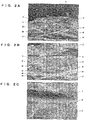
- FIGS. 2 and 3 show enlarged SEM photographs of the carbon nanotube sheet 1 and the carbon nanotube layer 3 in an entangled state.
- Reference numeral 4f in FIG. 2 denotes fibers in the carbonized layer 4.
- FIGS. 2B and 2C are enlarged photographs showing the ranges of b and c of FIG. 2A.
- FIGS. 2A to 2C show that the fibers 4f of the carbonized layer 4 are bonded and entangled with the carbon nanotube layer 3.
- FIGS. 3A and 3B show the surface of the carbon nanotube layer 3 in an entangled state.
- FIG. 3C shows a cross section of the carbon nanotube layer 3 in an entangled state.
- reference numeral 3t denotes the (inclined) distal end portions of the carbon nanotubes
- reference numeral 3m denotes the (substantially longitudinally entangled) intermediate portions of the carbon nanotubes
- reference numeral 3r denotes the (inclined) proximal end portions of the carbon nanotubes.
- the carbon nanotube layer 3 in an entangled state in FIG. 3 is reduced in thickness to about 8 to 10 ⁇ m from about 180 ⁇ m by pressing.
- the carbon nanotube sheet allows the fibrous carbonized layer 4 to retain the carbon nanotube layer 3.
- the carbon nanotube sheet 1 is so large as to be collected in a roll form, the carbon nanotube layer 3 can be obtained in a sheet form without being deformed.
- the carbon nanotube layer 3 in an entangled state in particular, can improve the wettability and thermal conductivity of the obtained carbon nanotube sheet 1 and more firmly keep the sheet form.
- the carbon nanotube layer 3 is shaped like a brush.
- the production method schematically includes a combining step 73 of combining carbon nanotubes and a film sheet of thermosetting resin (e.g., phenol resin, epoxy resin, melanin resin, urea resin, or alkyd resin) into a composite sheet, and a carbonizing step 74 of carbonizing the film sheet of the composite sheet into the fibrous carbonized layer 4.
- the film sheet of thermosetting resin is an example of a thermally carbonized sheet.
- the thermally carbonized sheet may be any sheet thermally carbonized into a fibrous sheet.
- a nonwoven wood-base sheet of cellulose may be used in addition to a film sheet of thermosetting resin.
- the film sheet of thermosetting resin will be simply referred to as the film sheet.
- numerous carbon nanotubes gather into a brush form as in the configuration of the carbon nanotube layer 3 but the carbon nanotubes are discriminated from the carbon nanotubes layer 3 before being retained by the carbonized layer 4.
- the film sheet is heated and is pressed to the carbon nanotubes, forming the composite sheet containing the carbon nanotubes and the film sheet.
- the composite sheet is heated in an atmosphere of nitrogen gas so as to carbonize the film sheet into the fibrous carbonized layer 4. Since the carbonized layer 4 and the carbon nanotube layer 3 are both made of carbon, the fibrous carbonized layer 4 is bonded and entangled with the proximal end portions of the carbon nanotubes of the carbon nanotube layer 3 so as to retain the carbon nanotube layer 3.
- a production unit 11 includes a delivery unit 12 that delivers a substrate (holding carbon nanotubes 30) K and a film sheet 40, a combining unit 13 that combines the delivered carbon nanotubes 30 and the film sheet 40 into a composite sheet 10, a carbonizing unit 14 that carbonizes the film sheet 40 of the composite sheet 10 to form the composite sheet 10 into the carbon nanotube sheet 1, and a collecting unit 15 that peels the substrate K from the carbon nanotube sheet 1 and collects the carbon nanotube sheet 1, the substrate K holding the carbon nanotube layer 3 of the carbon nanotube sheet 1.
- the combining unit 13 and the carbonizing unit 14 perform the combining step 73 and the carbonizing step 74, respectively, in the production method.
- the carbon nanotubes 30 (the substrate K holding the carbon nanotubes 30) and the film sheet 40 are belt-shaped and are delivered in batches or continuously from the delivery unit 12 to the collecting unit 15 in the longitudinal direction.
- the carbon nanotubes 30 are combined into the carbon nanotube layer 3 in the combining unit 13 and the film sheet 40 is carbonized into the fibrous carbonized layer 4 in the carbonizing unit 14.
- the production unit 11 has multiple rolls, which will be described later. The axes of these rolls are horizontally oriented in parallel.
- the delivery unit 12 includes a first feed roll 21 and a second feed roll 22.
- the first feed roll 21 has a roll of the substrate (holding the carbon nanotubes 30) K and is configured to deliver the carbon nanotubes 30 with the substrate K in batches or continuously.
- the second feed roll 22 has a roll of the film sheet 40 and is configured to deliver the film sheet 40 in batches or continuously.
- the delivery unit 12 has upper and lower guide rolls 24 that deliver the substrate K, the carbon nanotubes 30 retained by the substrate K, and the film sheet 40 to the combining unit 13 from the delivery positions to a substantially horizontal position.
- the upper and lower guide rolls 24 are spaced such that the substrate (holding the carbon nanotubes 30) K and the film sheet 40 gradually approach each other and do not come into contact with each other before the combining unit 13.
- the rolled substrate (holding the carbon nanotubes 30) K on the first feed roll 21 is delivered such that the carbon nanotubes 30 face the film sheet 40, that is, the substrate K comes into contact with the guide roll 24.
- the combining unit 13 has upper and lower press rolls 31 (31a, 31b) that press the substrate (holding the carbon nanotubes 30) K and the film sheet 40 to combine the carbon nanotubes 30 and the film sheet 40.
- the upper and lower press rolls 31 press the substrate (holding the carbon nanotubes 30) K and the film sheet 40 that are stacked and passed between the upper and lower press rolls 31.
- the press roll 31(31b) on the film sheet 40 includes a heater 34 for heating the film sheet 40 to be passed and pressed.
- the carbonizing unit 14 includes a furnace 41 that can be brought into an atmosphere of inert gas and allows passage of the composite sheet 10 to be heated, a gas feeder 47 that supplies inert gas (e.g., nitrogen gas) into the furnace 41, and a pump 48 that discharges gas from the inside of the furnace 41.
- the gas feeder 47 and the pump 48 are each connected to the inside of the furnace 41 via a pipe 49 and a valve (not shown).
- the furnace 41 includes an electric furnace heater 44 that heats the inside of the furnace 41 to a predetermined temperature.
- the film sheet 40 is heated and shrunk into the fibrous carbonized layer 4, which deforms the carbon nanotube sheet 1 to be produced.
- a stiffener belt (an example of a stiffening member) 61 is extended in contact with the film sheet 40 (carbonized layer 4) in the furnace 41 so as to keep the flat shape of the film sheet 40.
- a tension is applied to the stiffener belt 61 to keep the flatness of the stiffener belt 61.
- the stiffener belt 61 to be resistant to the tension and heat is preferably made of metals.
- the production unit 11 includes a tension roll 65 having the looped stiffener belt 61 downstream of the furnace 41 and driving rolls 66 that drive the stiffener belt 61. In other words, the stiffener belt 61 is looped over the press roll 31(37b), the tension roll 65, and the driving rolls 66 near the film sheet 40.
- the collecting unit 15 includes a peeling roll 55 located on the substrate K so as to guide the substrate K in a direction in which the substrate K is peeled from the carbon nanotubes sheet 1, a substrate collecting roll 51 that collects the substrate K peeled from the carbon nanotube sheet 1, and a product collecting stand 52 for collecting the carbon nanotube sheet 1 produced by peeling the substrate K.
- the production method for the carbon nanotube sheet 1 using the production unit 11 will be specifically described below.
- the carbon nanotube layer 3 is formed beforehand on the surface of the belt-shaped substrate K and then the carbon nanotubes 30 retained by the substrate K are rolled with the substrate K. Subsequently, the rolled substrate (holding the carbon nanotubes 30) K is set on the first feed roll 21 while the rolled film sheet 40 is additionally prepared on the second feed roll 22.
- the substrate K is then delivered from the first feed roll 21.
- the delivered substrate K passes over one of the guide rolls 24, between the upper and lower press rolls 31, through the furnace 41, and over the peeling roll 55 and then is wound up by the substrate collecting roll 51.
- the film sheet 40 is delivered from the second feed roll 22.
- the delivered film sheet 40 passes over the other guide roll 24, between the upper and lower press rolls 31, and through the furnace 41 and then is collected by the product collecting stand 52.
- the film sheet 40 is brought into contact with (restrained by) the stiffener belt 61 in the furnace 41.
- the gas feeder 47 supplies nitrogen gas into the furnace 41 and discharges gas from the inside of the furnace 41 with the pump 48, bringing the inside of the furnace 41 into an atmosphere of nitrogen gas.
- the electric furnace heater 44 heats the inside of the furnace 41 to a predetermined temperature (e.g., 400°C).
- the predetermined temperature is 400 to 700°C, preferably about 600°C.
- the heat-up time ranges from 1 to 10°G per minute, preferably from 2 to 5°C per minute.
- the heater 34 of the press roll 31(31b) on the film sheet 40 heats the press roll 31b to another predetermined temperature (e.g., 130°C).
- the substrate collecting roll 51 and the driving rolls 66 are rotated to deliver the substrate K and the film sheet 40 (the carbonized layer 4 from the carbonizing unit 14) in batches from the delivery unit 12 to the collecting unit 15.
- the press roll 31 heats the film sheet 40 and presses the carbon nanotubes 30 (e.g., a pressure of 2 MPa).
- the pressure substantially ranging from 6 to 15 MPa may be 2 to 30 MPa.
- the composite sheet 10 is heated in the atmosphere of nitrogen gas in the furnace 41. This does not allow a reaction of the carbon nanotube layer 3 but carbonizes the film sheet 40 into the fibrous carbonized layer 4.
- the composite sheet 10 is stopped only for a predetermined time (e.g., two to three hours) and is heated to the predetermined temperature in the carbonizing unit 14.
- the film sheet 40 is heated and shrunk into the fibrous carbonized layer 4.
- the film sheet 40 in contact with (restrained by) the stiffener belt 61 does not bend the flat shape of the carbon nanotube sheet 1.
- the shrinkage brings the carbon nanotubes close to one another in the carbon nanotube layer 3, increasing the density of the carbon nanotube layer 3.
- the substrate K is peeled from the carbon nanotube sheet 1 by the peeling roll 55 and then is collected by the substrate collecting roll 51, allowing the product collecting stand 52 to collect the carbon nanotube sheet 1 in batches.
- the obtained carbon nanotube sheet 1 had lower conductivity (the characteristic of the carbon nanotube is improved) than a vertically aligned carbon nanotube sheet retained by an adhesive or the like. This is because the film sheet 40 carbonized into the fibrous carbonized layer 4 shrinks to about one quarter the original area so as to substantially quadruple the density of the carbon nanotube layer 3 retained by the fibrous carbonized layer 4.
- the carbon nanotube layer 3 can be obtained in a sheet form without being deformed.
- the density of the carbon nanotube layer 3 of the carbon nanotube sheet 1 increases so as to improve the characteristic of the carbon nanotube.
- the carbon nanotube sheet 1 is not bent and thus can have a versatile flat shape.
- the carbon nanotube sheet 1 continuously produced in batches can improve production efficiency.
- the carbon nanotube layer 3 is retained on the front side (that is, one surface) of the fibrous carbonized layer 4 (see FIG. 1 ).
- carbon nanotube layers 3 are retained on front and back sides (that is, both surfaces) of a fibrous carbonized layer 4 (see FIG. 6 ).
- a production method according to the second embodiment will be described below regarding different configurations from those of the first embodiment. The same configurations as those of the first embodiment are indicated by the same reference numerals and the explanation thereof is omitted.
- carbon nanotubes 30 retain the front and back sides of a film sheet 40 unlike in the combining step 73 of the production method according to the first embodiment, in which the film sheet 40 is pressed to the carbon nanotubes 30.
- a production unit 11 used for the production method according to the second embodiment will be first described below.
- a delivery unit 12 in the production unit 11 has a third feed roll 23 as well.
- the third feed roll 23 has a roll of a substrate (retaining the carbon nanotubes 30) K and can continuously deliver the carbon nanotubes 30 with the substrate K.
- the third feed roll 23 is located with a second feed roll 22 disposed between the first feed roll 21 and the third feed roll 23.
- the delivery unit 12 includes upper and lower guide rolls 24 spaced such that the upper and lower substrates (each holding the carbon nanotubes 30) K and the film sheet 40 therebetween gradually approach each other and do not come into contact with each other before a combining unit 13.
- the combining unit 13 in the production unit 11 includes upper and lower press rolls 31 that press the carbon nanotube 30 from the front and back sides of the film sheet 40, combining the upper and lower carbon nanotubes 30 and the film sheet 40 therebetween.
- the upper and lower press rolls 31 (31a, 31b) each include a heater 34, allowing the press rolls 31 to heat the film sheet 40 through the upper and lower substrates (holding the carbon nanotubes) K.
- a furnace 41 of a carbonizing unit 14 in the production unit 11 contains stiffener plates (an example of a stiffening member) 64 instead of the stiffener belt 61.
- the stiffener plates 64 hold (restrain) a composite sheet 10 (carbon nanotube sheet 1) along with the upper and lower substrates K. This keeps the flat shape of the composite sheet 10 and prevents deformation.
- a collecting unit 15 in the production unit 11 has two peeling rolls 55, specifically, upper and lower peeling rolls 55 (55a, 55b).
- the upper peeling roll 55a peels the substrate K located on the carbon nanotube sheet 1 while the lower peeling roll 55b peels the substrate K located under the carbon nanotube sheet 1.
- the collecting unit 15 further includes two substrate collecting rolls, specifically, upper and lower substrate collecting rolls 51 and 53.
- the one substrate collecting roll 51 collects one of the substrates K peeled from the carbon nanotube sheet 1 while the other substrate collecting roll 53 collects the other substrate K peeled from the carbon nanotube sheet 1.
- the upper and lower substrate collecting rolls 51 and 53 are disposed with a product collecting stand 52 located between the substrate collecting rolls 51 and 53.
- the production method for the carbon nanotube sheet 1 using the production unit 11 will be specifically described below.
- the rolled substrate (holding the carbon nanotubes 30) K is set beforehand on the third feed roll 23 as well as the first feed roll 21.
- the substrate K is then delivered also from the third feed roll 23.
- the delivered substrate K passes over the other guide roll 24, over the other press roll 31b, through the furnace 41, and over the other peeling roll 55b and then is wound up by the other substrate collecting roll 53.
- the film sheet 40 delivered from the second feed roll 22 passes between the upper and lower guide rolls 24, between the upper and lower press rolls 31, and through the furnace 41 so as to be located between the upper and lower carbon nanotubes 30, and then the film sheet 40 is collected by the product collecting stand 52.
- the upper and lower substrates K are held between the stiffener plates 64 in the furnace 41.
- the upper and lower substrate collecting rolls 51 and 53 are rotated to continuously deliver the upper and lower substrates K and the film sheet 40 (the carbonized layer 4 from the carbonizing unit 14) from the delivery unit 12 to the collecting unit 15.
- the press rolls 31 press the film sheet 40 held between the upper and lower carbon nanotubes 30 from the front and back sides of the film sheet 40.
- the upper and lower carbon nanotubes 30 are heated along with the film sheet 40.
- the film sheet 40 is heated and shrunk into the fibrous carbonized layer 4 held (restrained) between the stiffener plates 64, keeping the flat shape of the fibrous carbonized layer 4 without bending the carbon nanotubes.
- the shrinkage brings the carbon nanotubes to close to one another in the carbon nanotube layer 3, increasing the density of the carbon nanotube layer 3.
- the production method for the carbon nanotube sheet 1 according to the second embodiment can obtain the effect of the first embodiment and retain the continuously produced carbon nanotube layers 3 on the front and back sides (both surfaces) of the fibrous carbonized layer 4, thereby further increasing the production efficiency.
- a production method in a production method according to a third embodiment, two layers of vertically aligned carbon nanotubes are pressed together into a single layer that is used as the carbon nanotubes 30 in the combining step 73 of the first embodiment.
- the production method according to the third embodiment will be described below regarding different configurations from those of the first embodiment.
- the same configurations as those of the first embodiment are indicated by the same reference numerals and the explanation thereof is omitted.
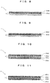
- a carbon nanotube layer 3 of a carbon nanotubes sheet 1 produced by the production method includes a sparse layer 3s close to a carbonized layer 4 and a dense layer 3d separated from the carbonized layer 4 (see FIG. 8 ) or includes the dense layer 3d close to the carbonized layer 4 and the sparse layer 3s separated from the carbonized layer 4 (see FIG. 9 ).
- a production unit 11 according to the third embodiment is different from that of the first embodiment only in the layer set on a first feed roll 21. Specifically, the two layers of vertically aligned carbon nanotubes are pressed together into a single layer and then a rolled substrate K holding the carbon nanotubes 30 is set on the first feed roll 21 of the third embodiment. In the two layers of the vertically aligned carbon nanotubes, the carbon nanotubes making up the respective layers vary in length and/or density. The lengths and/or densities of the carbon nanotubes are determined according to the percentage of voids and thickness of the carbon nanotube layer 3 to be obtained. Other configurations of the production unit 11 and the production method are identical to those of the first embodiment.
- the production method for the carbon nanotube sheet 1 according to the third embodiment can obtain the effect of the first embodiment and adjust the percentage of voids and thickness of the carbon nanotube layer 3 to be obtained.
- a production method in a production method according to a fourth embodiment, two layers of vertically aligned carbon nanotubes are pressed together into a single layer that is used as the carbon nanotubes 30 in the combining step 73 of the second embodiment.
- the production method according to the fourth embodiment will be described below regarding different configurations from those of the second embodiment.
- the same configurations as those of the second embodiment are indicated by the same reference numerals and the explanation thereof is omitted.
- a carbon nanotube layer 3 of a carbon nanotube sheet 1 produced by the production method includes a sparse layer 3s close to a carbonized layer 4 and a dense layer 3d separated from the carbonized layer 4 (see FIG. 10 ) or includes the dense layer 3d close to the carbonized layer 4 and the sparse layer 3s separated from the carbonized layer 4 (see F2G. 11).
- a production unit 11 according to the fourth embodiment is different from that of the second embodiment only in the layers set on a first feed roll 21 and a third feed roll 23. Specifically, the two layers of vertically aligned carbon nanotubes 30 are pressed into a single layer and then a rolled substrate K holding the carbon nanotubes 30 is set on each of the first feed roll 21 and the third feed roll 23 of the fourth embodiment.
- the two layers of the vertically aligned carbon nanotubes include different carbon nanotubes in length and/or density. The lengths and/or densities are determined according to the percentage of voids and thickness of the carbon nanotube layer 3 to be obtained.
- Other configurations of the production unit 11 and the production method are identical to those of the second embodiment.
- the production method for the carbon nanotube sheet 1 according to the fourth embodiment can obtain the effect of the second embodiment and adjust the percentage of voids and thickness of the carbon nanotube layer 3 to be obtained.
- an example of inert gas is, but not exclusively, nitrogen gas.
- Gas containing rare-gas elements such as helium, neon, and argon may be used.
- the carbonizing step is performed after the combining step.
- the combining step and the carbonizing step may be performed at the same time.
- an example of a thermally carbonized sheet is, but not exclusively, the film sheet 40 made of thermosetting resin or a nonwoven wood-base sheet. Any sheets that are carbonized into fibers by heating may be used.
- the substrate K and the film sheet 40 are delivered in batches.
- the substrate K and the film sheet 40 may be continuously delivered so as to further increase the production efficiency.
- the carbon nanotubes of the carbon nanotube layer 3 are not specifically described.
- the carbon nanotubes may be single-walled nanotubes or multi-walled nanotubes (including double-walled nanotubes).
- the first to fourth embodiments do not specifically describe a pressure of the film sheet 40 to the carbon nanotubes 30 in the combining step in the production methods.
- the pressure is optionally set as long as the distal and proximal end portions of the carbon nanotubes 30 are inclined and the intermediate portions of the carbon nanotubes 30 are entangled with one another (the carbon nanotubes 30 are pressed to have about up to a half of the thickness of the carbon nanotube 30).
- This production method obtains the carbon nanotube sheet 1 shown in FIG. 1B , that is, the carbon nanotube sheet 1 including the carbon nanotube layer 3 in an entangled state.
- the production method can obtain the effects of the first to fourth embodiments, improve the wettability and thermal conductivity of the obtained carbon nanotube sheet 1, and more reliably keep the sheet form of the carbon nanotube sheet 1.
Landscapes
- Chemical & Material Sciences (AREA)
- Engineering & Computer Science (AREA)
- Materials Engineering (AREA)
- Nanotechnology (AREA)
- Organic Chemistry (AREA)
- Inorganic Chemistry (AREA)
- Ceramic Engineering (AREA)
- Carbon And Carbon Compounds (AREA)
Abstract
Description
- The present invention relates to a carbon nanotubes sheet and a production method for the carbon nanotube sheet.
- Carbon nanotube materials have various characteristics and are expected to be applied to various fields. Individual vertically aligned carbon nanotubes, that is, vertically aligned carbon nanotubes particularly have large surface areas and thus the characteristics of the carbon nanotubes are demonstrated in wide application areas.
- Generally, such vertically aligned carbon nanotubes are formed on a substrate surface in the production process. In a proposed method, vertically aligned carbon nanotubes are peeled from a substrate surface using water and the temperature of water (for example, see Patent Literature 1).
- Patent Literature 1: Japanese Patent Laid-Open No.
2009-149517 - In the method of
Patent Literature 1, however, carbon nanotubes are not retained at all after being peeled from a substrate, leading to a weak force for keeping the sheet form of the carbon nanotubes. If carbon nanotubes are peeled with a wide area from the substrate, unfortunately, the sheet form of the carbon nanotubes is easily deformed during peeling. - Moreover, in the method of
Patent Literature 1, the carbon nanotubes can be peeled from the substrate while keeping shape characteristics obtained on the substrate. However, high-function carbon nanotubes have been demanded in recent years and the characteristics of carbon nanotubes are not improved by peeling. - An object of the present invention is to provide a carbon nanotube sheet and a production method for the carbon nanotube sheet which can improve the characteristics of carbon nanotubes while keeping a sheet form over a large area.
- In order to solve the problems, a carbon nanotubes sheet according to a first aspect of the present invention includes a carbon nanotube layer that contains numerous vertically aligned carbon nanotubes and a fibrous carbonized layer that retains the proximal end portions of the carbon nanotubes,
the carbon nanotube layer being configured such that the proximal end portions and distal end portions of the carbon nanotubes are inclined and the intermediate portions of the carbon nanotubes are entangled with one another. - In order to solve the problems, a production method for a carbon nanotube sheet according to a second aspect of the present invention includes: a combining step of forming a composite sheet by thermally pressing a thermally carbonized sheet to carbon nanotubes; and
a carbonizing step of carbonizing the thermally carbonized sheet in the composite sheet by heating the composite sheet in an atmosphere of inert gas,
the thermally carbonized sheet being heated into a fibrous form. - In a production method for a carbon nanotube sheet according to a third aspect of the present invention, bending of the composite sheet in the carbonizing step of the production method according to the second aspect is restricted by a stiffening member.
- In a production method for a carbon nanotube sheet according to a fourth aspect of the present invention, the carbon nanotubes in the combining step of the production method according to one of the second and third aspects are two layers of vertically aligned carbon nanotubes that are stacked by pressing the layers together.
- In a production method for a carbon nanotube sheet according to a fifth aspect of the present invention, in the two layers of the vertically aligned carbon nanotubes, in the production method according to the fourth aspect, the carbon nanotubes making up the respective layers vary in length and/or density.
- In a production method for a carbon nanotube sheet according to a sixth aspect of the present invention, the pressing of the thermally carbonized sheet to the carbon nanotubes in the combining step of the production method according to any one of the second to fifth aspects is to hold the thermally carbonized sheet with the vertically aligned carbon nanotube from the front and back sides of the sheet.
- In a production method for a carbon nanotube sheet according to a seventh aspect of the present invention, the thermally carbonized sheet of the production method according to any one of the second to sixth aspects is delivered from a location for the combining step to a location for the carbonizing step and is delivered in batches or continuously.
- The carbon nanotube sheet and the production method for the carbon nanotube sheet can keep a sheet form even with a large area, thereby improving the characteristics of carbon nanotubes.
-
- [
FIG. 1] FIGS. 1A and 1B are enlarged cross-sectional views of a carbon nanotube sheet according to a first embodiment of the present invention,FIG. 1A showing a brush-like carbon nanotube layer,FIG. 1B showing a carbon nanotube layer in an entangled state. - [
FIG. 2] FIGS. 2A to 2C are enlarged SEM photographs of the carbon nanotube sheet,FIG. 2A showing a cross section with a 500-fold magnification,FIG. 2B showing a cross section with a 2000-fold magnification,FIG. 2C showing a cross section with a 5000-fold magnification. - [
FIG. 3] FIGS. 3A to 3C are enlarged SEM photographs of the carbon nanotube layer in an entangled state,FIG. 3A showing a surface with a 11000-fold magnification,FIG. 3B showing the surface with a 10000-fold magnification, -
FIG. 3C showing a cross section with a 13000-fold magnification. - [
FIG. 4] FIG. 4 is a schematic process diagram showing a production method for the carbon nanotube sheet. - [
FIG. 5] FIG. 5 is a schematic diagram showing a production unit used for the production method. - [
FIG. 6] FIG. 6 is an enlarged cross-sectional view of a carbon nanotube sheet according to a second embodiment of the present invention. - [
FIG. 7] FIG. 7 is a schematic diagram showing a production unit used for a production method for the carbon nanotube sheet. - [
FIG. 8] FIG. 8 is an enlarged cross-sectional view showing a configuration of a carbon nanotube sheet according to a third embodiment of the present invention. - [
FIG. 9] FIG 9 is an enlarged cross-sectional view showing another configuration of the carbon nanotube sheet. - [
FIG. 10] FIG. 10 is an enlarged cross-sectional view showing a configuration of a carbon nanotube sheet according to a fourth embodiment of the present invention. - [
FIG. 11] FIG. 11 is an enlarged cross-sectional view showing another configuration of the carbon nanotube sheet. - A carbon nanotube sheet and a production method for the carbon nanotube sheet according to a first embodiment of the present invention will be described below with reference to the accompanying drawings.
- The carbon nanotube sheet will be first described below.
- As shown in
FIG. 1 , acarbon nanotube sheet 1 includes acarbon nanotube layer 3 that contains numerous vertically aligned carbon nanotubes and a fibrous carbonizedlayer 4 that retains the proximal end portions of the carbon nanotubes to keep the layer shape of thecarbon nanotube layer 3. Specifically, the proximal end portions of the carbon nanotubes are not deformed by the fibrous carbonizedlayer 4, keeping the brush-like form of thecarbon nanotube layer 3 shown inFIG. 1A from coming apart. As a matter of course, if thecarbon nanotube layer 3 is placed in an entangled state as shown inFIG. 1B , the carbon nanotubes are bonded with one another with a van der Waals force, thereby further keeping them from coming apart. In this case, the entangled state means that the distal and proximal end portions of carbon nanotubes are inclined with entangled intermediate portions. -
FIGS. 2 and3 show enlarged SEM photographs of thecarbon nanotube sheet 1 and thecarbon nanotube layer 3 in an entangled state.Reference numeral 4f inFIG. 2 denotes fibers in the carbonizedlayer 4.FIGS. 2B and 2C are enlarged photographs showing the ranges of b and c ofFIG. 2A. FIGS. 2A to 2C show that thefibers 4f of thecarbonized layer 4 are bonded and entangled with thecarbon nanotube layer 3.FIGS. 3A and 3B show the surface of thecarbon nanotube layer 3 in an entangled state.FIG. 3C shows a cross section of thecarbon nanotube layer 3 in an entangled state. InFIG. 3C ,reference numeral 3t denotes the (inclined) distal end portions of the carbon nanotubes,reference numeral 3m denotes the (substantially longitudinally entangled) intermediate portions of the carbon nanotubes, andreference numeral 3r denotes the (inclined) proximal end portions of the carbon nanotubes. Thecarbon nanotube layer 3 in an entangled state inFIG. 3 is reduced in thickness to about 8 to 10 µm from about 180 µm by pressing. - The carbon nanotube sheet allows the fibrous
carbonized layer 4 to retain thecarbon nanotube layer 3. Thus, even if thecarbon nanotube sheet 1 is so large as to be collected in a roll form, thecarbon nanotube layer 3 can be obtained in a sheet form without being deformed. - The
carbon nanotube layer 3 in an entangled state, in particular, can improve the wettability and thermal conductivity of the obtainedcarbon nanotube sheet 1 and more firmly keep the sheet form. - A production method for the
carbon nanotube sheet 1 will be described below. In the following example, thecarbon nanotube layer 3 is shaped like a brush. - As shown in
FIG. 4 , the production method schematically includes a combiningstep 73 of combining carbon nanotubes and a film sheet of thermosetting resin (e.g., phenol resin, epoxy resin, melanin resin, urea resin, or alkyd resin) into a composite sheet, and a carbonizingstep 74 of carbonizing the film sheet of the composite sheet into the fibrouscarbonized layer 4. The film sheet of thermosetting resin is an example of a thermally carbonized sheet. The thermally carbonized sheet may be any sheet thermally carbonized into a fibrous sheet. For example, a nonwoven wood-base sheet of cellulose may be used in addition to a film sheet of thermosetting resin. In the following description, the film sheet of thermosetting resin will be simply referred to as the film sheet. Furthermore, numerous carbon nanotubes gather into a brush form as in the configuration of thecarbon nanotube layer 3 but the carbon nanotubes are discriminated from thecarbon nanotubes layer 3 before being retained by thecarbonized layer 4. - In the combining
step 73, the film sheet is heated and is pressed to the carbon nanotubes, forming the composite sheet containing the carbon nanotubes and the film sheet. In the carbonizingstep 74, the composite sheet is heated in an atmosphere of nitrogen gas so as to carbonize the film sheet into the fibrouscarbonized layer 4. Since thecarbonized layer 4 and thecarbon nanotube layer 3 are both made of carbon, the fibrouscarbonized layer 4 is bonded and entangled with the proximal end portions of the carbon nanotubes of thecarbon nanotube layer 3 so as to retain thecarbon nanotube layer 3. - An example of a production unit used for the production method will be described below.
- As shown in
FIG. 5 , aproduction unit 11 includes adelivery unit 12 that delivers a substrate (holding carbon nanotubes 30) K and afilm sheet 40, a combiningunit 13 that combines the deliveredcarbon nanotubes 30 and thefilm sheet 40 into acomposite sheet 10, a carbonizingunit 14 that carbonizes thefilm sheet 40 of thecomposite sheet 10 to form thecomposite sheet 10 into thecarbon nanotube sheet 1, and a collectingunit 15 that peels the substrate K from thecarbon nanotube sheet 1 and collects thecarbon nanotube sheet 1, the substrate K holding thecarbon nanotube layer 3 of thecarbon nanotube sheet 1. In this configuration, the combiningunit 13 and the carbonizingunit 14 perform the combiningstep 73 and the carbonizingstep 74, respectively, in the production method. Moreover, the carbon nanotubes 30 (the substrate K holding the carbon nanotubes 30) and thefilm sheet 40 are belt-shaped and are delivered in batches or continuously from thedelivery unit 12 to the collectingunit 15 in the longitudinal direction. As a matter of course, thecarbon nanotubes 30 are combined into thecarbon nanotube layer 3 in the combiningunit 13 and thefilm sheet 40 is carbonized into the fibrouscarbonized layer 4 in the carbonizingunit 14. Theproduction unit 11 has multiple rolls, which will be described later. The axes of these rolls are horizontally oriented in parallel. - The
delivery unit 12 includes afirst feed roll 21 and asecond feed roll 22. Thefirst feed roll 21 has a roll of the substrate (holding the carbon nanotubes 30) K and is configured to deliver thecarbon nanotubes 30 with the substrate K in batches or continuously. Thesecond feed roll 22 has a roll of thefilm sheet 40 and is configured to deliver thefilm sheet 40 in batches or continuously. Thedelivery unit 12 has upper and lower guide rolls 24 that deliver the substrate K, thecarbon nanotubes 30 retained by the substrate K, and thefilm sheet 40 to the combiningunit 13 from the delivery positions to a substantially horizontal position. The upper and lower guide rolls 24 are spaced such that the substrate (holding the carbon nanotubes 30) K and thefilm sheet 40 gradually approach each other and do not come into contact with each other before the combiningunit 13. The rolled substrate (holding the carbon nanotubes 30) K on thefirst feed roll 21 is delivered such that thecarbon nanotubes 30 face thefilm sheet 40, that is, the substrate K comes into contact with theguide roll 24. - The combining
unit 13 has upper and lower press rolls 31 (31a, 31b) that press the substrate (holding the carbon nanotubes 30) K and thefilm sheet 40 to combine thecarbon nanotubes 30 and thefilm sheet 40. The upper and lower press rolls 31 press the substrate (holding the carbon nanotubes 30) K and thefilm sheet 40 that are stacked and passed between the upper and lower press rolls 31. Particularly, the press roll 31(31b) on thefilm sheet 40 includes aheater 34 for heating thefilm sheet 40 to be passed and pressed. - The carbonizing
unit 14 includes afurnace 41 that can be brought into an atmosphere of inert gas and allows passage of thecomposite sheet 10 to be heated, agas feeder 47 that supplies inert gas (e.g., nitrogen gas) into thefurnace 41, and apump 48 that discharges gas from the inside of thefurnace 41. Thegas feeder 47 and thepump 48 are each connected to the inside of thefurnace 41 via apipe 49 and a valve (not shown). Thefurnace 41 includes anelectric furnace heater 44 that heats the inside of thefurnace 41 to a predetermined temperature. - The
film sheet 40 is heated and shrunk into the fibrouscarbonized layer 4, which deforms thecarbon nanotube sheet 1 to be produced. In order to prevent such deformation, a stiffener belt (an example of a stiffening member) 61 is extended in contact with the film sheet 40 (carbonized layer 4) in thefurnace 41 so as to keep the flat shape of thefilm sheet 40. A tension is applied to thestiffener belt 61 to keep the flatness of thestiffener belt 61. Thestiffener belt 61 to be resistant to the tension and heat is preferably made of metals. Theproduction unit 11 includes atension roll 65 having the loopedstiffener belt 61 downstream of thefurnace 41 and driving rolls 66 that drive thestiffener belt 61. In other words, thestiffener belt 61 is looped over the press roll 31(37b), thetension roll 65, and the driving rolls 66 near thefilm sheet 40. - The collecting
unit 15 includes a peelingroll 55 located on the substrate K so as to guide the substrate K in a direction in which the substrate K is peeled from thecarbon nanotubes sheet 1, asubstrate collecting roll 51 that collects the substrate K peeled from thecarbon nanotube sheet 1, and a product collecting stand 52 for collecting thecarbon nanotube sheet 1 produced by peeling the substrate K. - The production method for the
carbon nanotube sheet 1 using theproduction unit 11 will be specifically described below. - The
carbon nanotube layer 3 is formed beforehand on the surface of the belt-shaped substrate K and then thecarbon nanotubes 30 retained by the substrate K are rolled with the substrate K. Subsequently, the rolled substrate (holding the carbon nanotubes 30) K is set on thefirst feed roll 21 while the rolledfilm sheet 40 is additionally prepared on thesecond feed roll 22. - The substrate K is then delivered from the
first feed roll 21. The delivered substrate K passes over one of the guide rolls 24, between the upper and lower press rolls 31, through thefurnace 41, and over the peelingroll 55 and then is wound up by thesubstrate collecting roll 51. Similarly, thefilm sheet 40 is delivered from thesecond feed roll 22. The deliveredfilm sheet 40 passes over theother guide roll 24, between the upper and lower press rolls 31, and through thefurnace 41 and then is collected by theproduct collecting stand 52. Thefilm sheet 40 is brought into contact with (restrained by) thestiffener belt 61 in thefurnace 41. - Subsequently, the
gas feeder 47 supplies nitrogen gas into thefurnace 41 and discharges gas from the inside of thefurnace 41 with thepump 48, bringing the inside of thefurnace 41 into an atmosphere of nitrogen gas. Moreover, theelectric furnace heater 44 heats the inside of thefurnace 41 to a predetermined temperature (e.g., 400°C). The predetermined temperature is 400 to 700°C, preferably about 600°C. The heat-up time ranges from 1 to 10°G per minute, preferably from 2 to 5°C per minute. Meanwhile, theheater 34 of the press roll 31(31b) on thefilm sheet 40 heats thepress roll 31b to another predetermined temperature (e.g., 130°C). - After that, the
substrate collecting roll 51 and the driving rolls 66 are rotated to deliver the substrate K and the film sheet 40 (thecarbonized layer 4 from the carbonizing unit 14) in batches from thedelivery unit 12 to the collectingunit 15. Thus, in the combiningunit 13, thepress roll 31 heats thefilm sheet 40 and presses the carbon nanotubes 30 (e.g., a pressure of 2 MPa). The pressure substantially ranging from 6 to 15 MPa may be 2 to 30 MPa. In the carbonizingunit 14, thecomposite sheet 10 is heated in the atmosphere of nitrogen gas in thefurnace 41. This does not allow a reaction of thecarbon nanotube layer 3 but carbonizes thefilm sheet 40 into the fibrouscarbonized layer 4. With the batch delivery, thecomposite sheet 10 is stopped only for a predetermined time (e.g., two to three hours) and is heated to the predetermined temperature in the carbonizingunit 14. In this case, thefilm sheet 40 is heated and shrunk into the fibrouscarbonized layer 4. Thefilm sheet 40 in contact with (restrained by) thestiffener belt 61 does not bend the flat shape of thecarbon nanotube sheet 1. Moreover, the shrinkage brings the carbon nanotubes close to one another in thecarbon nanotube layer 3, increasing the density of thecarbon nanotube layer 3. In the collectingunit 15, the substrate K is peeled from thecarbon nanotube sheet 1 by the peelingroll 55 and then is collected by thesubstrate collecting roll 51, allowing the product collecting stand 52 to collect thecarbon nanotube sheet 1 in batches. - The electrical resistance of the collected
carbon nanotube sheet 1, a characteristic of the carbon nanotube, was 0.05Ω. Thus, the obtainedcarbon nanotube sheet 1 had lower conductivity (the characteristic of the carbon nanotube is improved) than a vertically aligned carbon nanotube sheet retained by an adhesive or the like. This is because thefilm sheet 40 carbonized into the fibrouscarbonized layer 4 shrinks to about one quarter the original area so as to substantially quadruple the density of thecarbon nanotube layer 3 retained by the fibrouscarbonized layer 4. - According to the production method for the
carbon nanotubes sheet 1 of the first embodiment, even if thecarbon nanotube sheet 1 is so large as to be collected in a roll form, thecarbon nanotube layer 3 can be obtained in a sheet form without being deformed. - Moreover, the density of the
carbon nanotube layer 3 of thecarbon nanotube sheet 1 increases so as to improve the characteristic of the carbon nanotube. - The
carbon nanotube sheet 1 is not bent and thus can have a versatile flat shape. - The
carbon nanotube sheet 1 continuously produced in batches can improve production efficiency. - In the
carbon nanotube sheet 1 according to the first embodiment, thecarbon nanotube layer 3 is retained on the front side (that is, one surface) of the fibrous carbonized layer 4 (seeFIG. 1 ). In acarbon nanotube sheet 1 according to a second embodiment, carbon nanotube layers 3 are retained on front and back sides (that is, both surfaces) of a fibrous carbonized layer 4 (seeFIG. 6 ). A production method according to the second embodiment will be described below regarding different configurations from those of the first embodiment. The same configurations as those of the first embodiment are indicated by the same reference numerals and the explanation thereof is omitted. - In the production method according to the second embodiment,
carbon nanotubes 30 retain the front and back sides of afilm sheet 40 unlike in the combiningstep 73 of the production method according to the first embodiment, in which thefilm sheet 40 is pressed to thecarbon nanotubes 30. - A
production unit 11 used for the production method according to the second embodiment will be first described below. - As shown in
FIG. 7 , adelivery unit 12 in theproduction unit 11 has athird feed roll 23 as well. Like afirst feed roll 21, thethird feed roll 23 has a roll of a substrate (retaining the carbon nanotubes 30) K and can continuously deliver thecarbon nanotubes 30 with the substrate K. Thethird feed roll 23 is located with asecond feed roll 22 disposed between thefirst feed roll 21 and thethird feed roll 23. Thedelivery unit 12 includes upper and lower guide rolls 24 spaced such that the upper and lower substrates (each holding the carbon nanotubes 30) K and thefilm sheet 40 therebetween gradually approach each other and do not come into contact with each other before a combiningunit 13. - The combining
unit 13 in theproduction unit 11 includes upper and lower press rolls 31 that press thecarbon nanotube 30 from the front and back sides of thefilm sheet 40, combining the upper andlower carbon nanotubes 30 and thefilm sheet 40 therebetween. Moreover, the upper and lower press rolls 31 (31a, 31b) each include aheater 34, allowing the press rolls 31 to heat thefilm sheet 40 through the upper and lower substrates (holding the carbon nanotubes) K. - A
furnace 41 of a carbonizingunit 14 in theproduction unit 11 contains stiffener plates (an example of a stiffening member) 64 instead of thestiffener belt 61. Thestiffener plates 64 hold (restrain) a composite sheet 10 (carbon nanotube sheet 1) along with the upper and lower substrates K. This keeps the flat shape of thecomposite sheet 10 and prevents deformation. - A collecting
unit 15 in theproduction unit 11 has two peeling rolls 55, specifically, upper and lower peeling rolls 55 (55a, 55b). Theupper peeling roll 55a peels the substrate K located on thecarbon nanotube sheet 1 while thelower peeling roll 55b peels the substrate K located under thecarbon nanotube sheet 1. The collectingunit 15 further includes two substrate collecting rolls, specifically, upper and lower substrate collecting rolls 51 and 53. The onesubstrate collecting roll 51 collects one of the substrates K peeled from thecarbon nanotube sheet 1 while the othersubstrate collecting roll 53 collects the other substrate K peeled from thecarbon nanotube sheet 1. The upper and lower substrate collecting rolls 51 and 53 are disposed with a product collecting stand 52 located between the substrate collecting rolls 51 and 53. - The production method for the
carbon nanotube sheet 1 using theproduction unit 11 will be specifically described below. - The rolled substrate (holding the carbon nanotubes 30) K is set beforehand on the
third feed roll 23 as well as thefirst feed roll 21. - The substrate K is then delivered also from the
third feed roll 23. The delivered substrate K passes over theother guide roll 24, over theother press roll 31b, through thefurnace 41, and over the other peelingroll 55b and then is wound up by the othersubstrate collecting roll 53. Meanwhile, thefilm sheet 40 delivered from thesecond feed roll 22 passes between the upper and lower guide rolls 24, between the upper and lower press rolls 31, and through thefurnace 41 so as to be located between the upper andlower carbon nanotubes 30, and then thefilm sheet 40 is collected by theproduct collecting stand 52. The upper and lower substrates K are held between thestiffener plates 64 in thefurnace 41. - After that, the upper and lower substrate collecting rolls 51 and 53 are rotated to continuously deliver the upper and lower substrates K and the film sheet 40 (the
carbonized layer 4 from the carbonizing unit 14) from thedelivery unit 12 to the collectingunit 15. In the combiningunit 13, the press rolls 31 press thefilm sheet 40 held between the upper andlower carbon nanotubes 30 from the front and back sides of thefilm sheet 40. At this point, the upper andlower carbon nanotubes 30 are heated along with thefilm sheet 40. In this case, thefilm sheet 40 is heated and shrunk into the fibrouscarbonized layer 4 held (restrained) between thestiffener plates 64, keeping the flat shape of the fibrouscarbonized layer 4 without bending the carbon nanotubes. The shrinkage brings the carbon nanotubes to close to one another in thecarbon nanotube layer 3, increasing the density of thecarbon nanotube layer 3. - The production method for the
carbon nanotube sheet 1 according to the second embodiment can obtain the effect of the first embodiment and retain the continuously produced carbon nanotube layers 3 on the front and back sides (both surfaces) of the fibrouscarbonized layer 4, thereby further increasing the production efficiency. - In a production method according to a third embodiment, two layers of vertically aligned carbon nanotubes are pressed together into a single layer that is used as the
carbon nanotubes 30 in the combiningstep 73 of the first embodiment. The production method according to the third embodiment will be described below regarding different configurations from those of the first embodiment. The same configurations as those of the first embodiment are indicated by the same reference numerals and the explanation thereof is omitted. - A
carbon nanotube layer 3 of acarbon nanotubes sheet 1 produced by the production method includes asparse layer 3s close to acarbonized layer 4 and adense layer 3d separated from the carbonized layer 4 (seeFIG. 8 ) or includes thedense layer 3d close to thecarbonized layer 4 and thesparse layer 3s separated from the carbonized layer 4 (seeFIG. 9 ). - A
production unit 11 according to the third embodiment is different from that of the first embodiment only in the layer set on afirst feed roll 21. Specifically, the two layers of vertically aligned carbon nanotubes are pressed together into a single layer and then a rolled substrate K holding thecarbon nanotubes 30 is set on thefirst feed roll 21 of the third embodiment. In the two layers of the vertically aligned carbon nanotubes, the carbon nanotubes making up the respective layers vary in length and/or density. The lengths and/or densities of the carbon nanotubes are determined according to the percentage of voids and thickness of thecarbon nanotube layer 3 to be obtained. Other configurations of theproduction unit 11 and the production method are identical to those of the first embodiment. - The production method for the
carbon nanotube sheet 1 according to the third embodiment can obtain the effect of the first embodiment and adjust the percentage of voids and thickness of thecarbon nanotube layer 3 to be obtained. - In a production method according to a fourth embodiment, two layers of vertically aligned carbon nanotubes are pressed together into a single layer that is used as the
carbon nanotubes 30 in the combiningstep 73 of the second embodiment. The production method according to the fourth embodiment will be described below regarding different configurations from those of the second embodiment. The same configurations as those of the second embodiment are indicated by the same reference numerals and the explanation thereof is omitted. - A
carbon nanotube layer 3 of acarbon nanotube sheet 1 produced by the production method includes asparse layer 3s close to acarbonized layer 4 and adense layer 3d separated from the carbonized layer 4 (seeFIG. 10 ) or includes thedense layer 3d close to thecarbonized layer 4 and thesparse layer 3s separated from the carbonized layer 4 (see F2G. 11). - A
production unit 11 according to the fourth embodiment is different from that of the second embodiment only in the layers set on afirst feed roll 21 and athird feed roll 23. Specifically, the two layers of vertically alignedcarbon nanotubes 30 are pressed into a single layer and then a rolled substrate K holding thecarbon nanotubes 30 is set on each of thefirst feed roll 21 and thethird feed roll 23 of the fourth embodiment. The two layers of the vertically aligned carbon nanotubes include different carbon nanotubes in length and/or density. The lengths and/or densities are determined according to the percentage of voids and thickness of thecarbon nanotube layer 3 to be obtained. Other configurations of theproduction unit 11 and the production method are identical to those of the second embodiment. - The production method for the
carbon nanotube sheet 1 according to the fourth embodiment can obtain the effect of the second embodiment and adjust the percentage of voids and thickness of thecarbon nanotube layer 3 to be obtained. - In the first to fourth embodiments, an example of inert gas is, but not exclusively, nitrogen gas. Gas containing rare-gas elements such as helium, neon, and argon may be used.
- In the production methods and the production units according to the first to fourth embodiments, the carbonizing step is performed after the combining step. As a matter of course, the combining step and the carbonizing step may be performed at the same time.
- Furthermore, in the first to fourth embodiments, an example of a thermally carbonized sheet is, but not exclusively, the
film sheet 40 made of thermosetting resin or a nonwoven wood-base sheet. Any sheets that are carbonized into fibers by heating may be used. - In the production methods according to the first to fourth embodiments, the substrate K and the film sheet 40 (the
carbonized layer 4 from the carbonizing unit 14) are delivered in batches. The substrate K and thefilm sheet 40 may be continuously delivered so as to further increase the production efficiency. - In the first to fourth embodiments, the carbon nanotubes of the carbon nanotube layer 3 (carbon nanotubes 30) are not specifically described. The carbon nanotubes may be single-walled nanotubes or multi-walled nanotubes (including double-walled nanotubes).
- The first to fourth embodiments do not specifically describe a pressure of the
film sheet 40 to thecarbon nanotubes 30 in the combining step in the production methods. The pressure is optionally set as long as the distal and proximal end portions of thecarbon nanotubes 30 are inclined and the intermediate portions of thecarbon nanotubes 30 are entangled with one another (thecarbon nanotubes 30 are pressed to have about up to a half of the thickness of the carbon nanotube 30). This production method obtains thecarbon nanotube sheet 1 shown inFIG. 1B , that is, thecarbon nanotube sheet 1 including thecarbon nanotube layer 3 in an entangled state. Thus, the production method can obtain the effects of the first to fourth embodiments, improve the wettability and thermal conductivity of the obtainedcarbon nanotube sheet 1, and more reliably keep the sheet form of thecarbon nanotube sheet 1.
Claims (7)
- A carbon nanotubes sheet comprising a carbon nanotubes layer that contains numerous vertically aligned carbon nanotubes and a fibrous carbonized layer that retains proximal end portions of the carbon nanotubes,
the carbon nanotube layer being configured such that the proximal end portions and distal end portions of the carbon nanotubes are inclined and intermediate portions of the carbon nanotubes are entangled with one another. - A production method for a carbon nanotube sheet, comprising:a combining step of forming a composite sheet by thermally pressing a thermally carbonized sheet to carbon nanotubes; anda carbonizing step of carbonizing the thermally carbonized sheet in the composite sheet by heating the composite sheet in an atmosphere of inert gas,the thermally carbonized sheet being heated into a fibrous form.
- The production method for the carbon nanotube sheet according to claim 2, wherein bending of the composite sheet in the carbonizing step is restricted by a stiffening member.
- The production method for the carbon nanotube sheet, according to one of claims 2 and 3, wherein the carbon nanotubes in the combining step are two layers of vertically aligned carbon nanotubes that are stacked by pressing the layers together.
- The production method for the carbon nanotubes sheet according to claim 4, wherein in the two layers of the vertically aligned carbon nanotubes, the carbon nanotubes making up the respective layers vary in length and/or density.
- The production method for the carbon nanotube sheet according to one of claims 2 and 3, wherein the pressing of the thermally carbonized sheet to the carbon nanotubes in the combining step is to hold the thermally carbonized sheet with the vertically aligned carbon nanotubes from front and back sides of the sheet.
- The production method for the carbon nanotube sheet according to one of claims 2 and 3, wherein the thermally carbonized sheet is delivered from a location for the combining step to a location for the carbonizing step and is delivered in batches or continuously.
Applications Claiming Priority (2)
| Application Number | Priority Date | Filing Date | Title |
|---|---|---|---|
| JP2013118393A JP2014234339A (en) | 2013-06-05 | 2013-06-05 | Carbon nanotube sheet and method for producing carbon nanotube sheet |
| PCT/JP2014/064358 WO2014196459A1 (en) | 2013-06-05 | 2014-05-30 | Carbon nanotube sheet and production method for carbon nanotube sheet |
Publications (2)
| Publication Number | Publication Date |
|---|---|
| EP3006398A1 true EP3006398A1 (en) | 2016-04-13 |
| EP3006398A4 EP3006398A4 (en) | 2017-01-18 |
Family
ID=52008105
Family Applications (1)
| Application Number | Title | Priority Date | Filing Date |
|---|---|---|---|
| EP14808111.0A Withdrawn EP3006398A4 (en) | 2013-06-05 | 2014-05-30 | Carbon nanotube sheet and production method for carbon nanotube sheet |
Country Status (6)
| Country | Link |
|---|---|
| US (1) | US9902618B2 (en) |
| EP (1) | EP3006398A4 (en) |
| JP (1) | JP2014234339A (en) |
| KR (1) | KR102293908B1 (en) |
| CN (1) | CN105164049B (en) |
| WO (1) | WO2014196459A1 (en) |
Families Citing this family (8)
| Publication number | Priority date | Publication date | Assignee | Title |
|---|---|---|---|---|
| JP6482966B2 (en) * | 2015-06-25 | 2019-03-13 | 日立造船株式会社 | Carbon nanotube web manufacturing method, carbon nanotube aggregate manufacturing method, and carbon nanotube web manufacturing apparatus |
| TWI721077B (en) | 2015-12-28 | 2021-03-11 | 日商日立造船股份有限公司 | Carbon nanotube composite material and manufacture method thereof |
| CN108430919B (en) * | 2015-12-28 | 2022-01-28 | 日立造船株式会社 | Carbon nanotube bonding sheet and method for producing carbon nanotube bonding sheet |
| JP6917725B2 (en) * | 2017-02-13 | 2021-08-11 | 日立造船株式会社 | Manufacturing method of carbon nanotube composite material, carbon nanotube composite material and anisotropic carbon nanotube composite material |
| US11084724B2 (en) * | 2017-12-07 | 2021-08-10 | Lintec Of America, Inc. | Transferring nanofiber forests between substrates |
| US11135827B2 (en) * | 2018-10-11 | 2021-10-05 | Lintec Of America, Inc. | Patterning a nanofiber forest |
| US11479438B2 (en) * | 2019-05-16 | 2022-10-25 | Lintec Of America, Inc. | Nanofiber structure applicator |
| WO2023085215A1 (en) * | 2021-11-12 | 2023-05-19 | 日本ゼオン株式会社 | Solar cell electrode, solar cell, and solar cell module |
Family Cites Families (17)
| Publication number | Priority date | Publication date | Assignee | Title |
|---|---|---|---|---|
| US6024350A (en) * | 1997-01-14 | 2000-02-15 | Black & Decker Inc. | Clamp for a power tool |
| WO2005044723A2 (en) | 2003-10-16 | 2005-05-19 | The University Of Akron | Carbon nanotubes on carbon nanofiber substrate |
| JP4940392B2 (en) * | 2005-03-08 | 2012-05-30 | 国立大学法人 名古屋工業大学 | Method for producing carbon nanostructured material |
| JP4696751B2 (en) * | 2005-07-26 | 2011-06-08 | 日立造船株式会社 | Method for producing electrode using carbon nanotube |
| US20100173228A1 (en) | 2006-12-14 | 2010-07-08 | University Of Wollongong | Nanotube and Carbon Layer Nanostructured Composites |
| AU2007332084A1 (en) * | 2006-12-14 | 2008-06-19 | University Of Wollongong | Nanotube and carbon layer nanostructured composites |
| CN101480858B (en) | 2008-01-11 | 2014-12-10 | 清华大学 | Carbon nano-tube composite material and preparation method thereof |
| CN101462391B (en) * | 2007-12-21 | 2013-04-24 | 清华大学 | Method for preparing carbon nano-tube composite material |
| CN101456277B (en) * | 2007-12-14 | 2012-10-10 | 清华大学 | Method for preparing carbon nanotube composite material |
| JP4628475B2 (en) | 2009-03-30 | 2011-02-09 | 国立大学法人 東京大学 | Carbon nanotube free-standing film and method for producing the same, and structure having carbon nanotube film and method for producing the same |
| FR2952631B1 (en) * | 2009-11-13 | 2012-01-13 | Commissariat Energie Atomique | PROCESS FOR PRODUCING CARBON NANOTUBES ON A SUBSTRATE |
| BR112012012979A2 (en) * | 2009-12-14 | 2019-09-24 | Applied Nanostructured Sols | flame resistant composite materials and articles containing carbon nanotube infused fiber materials. |
| CN101798076B (en) * | 2010-04-02 | 2012-02-29 | 上海交通大学 | Preparation method of composite sheet based on glassy carbon and carbon nanotubes |
| CN101880036B (en) | 2010-06-29 | 2013-02-13 | 清华大学 | Carbon nanotube composite structure |
| JP5605908B2 (en) * | 2011-02-15 | 2014-10-15 | 大陽日酸株式会社 | Four-layer catalyst base for CNT production, CNT with substrate carbonized layer, CNT with carbonized layer, CNT production method, CNT recovery method, and CNT continuous production apparatus |
| CN103058167B (en) * | 2012-12-05 | 2015-05-20 | 天津大学 | Composite material of carbon nanotube and carbon, and preparation method thereof |
| JP6008724B2 (en) * | 2012-12-07 | 2016-10-19 | 日立造船株式会社 | Method for manufacturing carbon nano-junction conductive material substrate |
-
2013
- 2013-06-05 JP JP2013118393A patent/JP2014234339A/en active Pending
-
2014
- 2014-05-30 EP EP14808111.0A patent/EP3006398A4/en not_active Withdrawn
- 2014-05-30 WO PCT/JP2014/064358 patent/WO2014196459A1/en not_active Ceased
- 2014-05-30 US US14/895,061 patent/US9902618B2/en not_active Expired - Fee Related
- 2014-05-30 KR KR1020157030747A patent/KR102293908B1/en not_active Expired - Fee Related
- 2014-05-30 CN CN201480022076.2A patent/CN105164049B/en not_active Expired - Fee Related
Non-Patent Citations (1)
| Title |
|---|
| See references of WO2014196459A1 * |
Also Published As
| Publication number | Publication date |
|---|---|
| US20160145105A1 (en) | 2016-05-26 |
| CN105164049A (en) | 2015-12-16 |
| KR102293908B1 (en) | 2021-08-24 |
| CN105164049B (en) | 2018-04-20 |
| KR20160014588A (en) | 2016-02-11 |
| EP3006398A4 (en) | 2017-01-18 |
| WO2014196459A1 (en) | 2014-12-11 |
| JP2014234339A (en) | 2014-12-15 |
| US9902618B2 (en) | 2018-02-27 |
Similar Documents
| Publication | Publication Date | Title |
|---|---|---|
| US9902618B2 (en) | Carbon nanotube sheet and production method for carbon nanotube sheet | |
| Mecklenburg et al. | On the manufacturing and electrical and mechanical properties of ultra-high wt.% fraction aligned MWCNT and randomly oriented CNT epoxy composites | |
| US8053069B2 (en) | High heat conduction composite material | |
| KR102089604B1 (en) | Composite nanofiber sheet | |
| JP5229934B2 (en) | High thermal conductivity composite material | |
| EP2149538B1 (en) | Interface-infused nanotube interconnect | |
| EP2554526A1 (en) | Carbon/carbon composite material and method of manufacture for same | |
| EP2289861A1 (en) | Carbon fiber carbon composite molded body, carbon fiber-reinforced carbon composite material and manufacturing method thereof | |
| JP2010013340A (en) | Graphite composite and method for producing the same | |
| WO2006051782A1 (en) | Metal base carbon fiber composite material and method for production thereof | |
| CN106898408A (en) | graphene-based electric conductor and preparation method thereof | |
| CN101708659B (en) | Mold for fiber reinforced composite dot matrix core board and wet method preparation process | |
| US20130266738A1 (en) | Method for making strip shaped graphene layer | |
| CN111696700A (en) | Metal structure having a desired combination of mechanical and electrical properties | |
| JP6559541B2 (en) | Method for producing composite of aluminum and carbon particles | |
| CN115057432B (en) | Graphene foam block, heat conducting sheet, gasket, arrangement device and preparation method | |
| JP2008235259A (en) | Manufacturing method of low thermal expansion linear body | |
| JP2018131344A (en) | Method for producing carbon nanotube composite, carbon nanotube composite and anisotropic carbon nanotube composite | |
| WO2008015952A1 (en) | Mold release sheet | |
| US9382118B2 (en) | Method of manufacturing graphene | |
| JP2010227963A (en) | Joining method using metal nanoparticles | |
| JP6498040B2 (en) | Composite of aluminum and carbon particles and insulating substrate | |
| JP6456449B2 (en) | Method for producing carbon nanotube sheet | |
| CN109273134B (en) | Preparation of graphene and graphene composite conductors from graphite | |
| CN118650939A (en) | A kind of ultra-high thermal conductivity graphene composite film and its preparation method and application |
Legal Events
| Date | Code | Title | Description |
|---|---|---|---|
| PUAI | Public reference made under article 153(3) epc to a published international application that has entered the european phase |
Free format text: ORIGINAL CODE: 0009012 |
|
| 17P | Request for examination filed |
Effective date: 20160105 |
|
| AK | Designated contracting states |
Kind code of ref document: A1 Designated state(s): AL AT BE BG CH CY CZ DE DK EE ES FI FR GB GR HR HU IE IS IT LI LT LU LV MC MK MT NL NO PL PT RO RS SE SI SK SM TR |
|
| AX | Request for extension of the european patent |
Extension state: BA ME |
|
| DAX | Request for extension of the european patent (deleted) | ||
| A4 | Supplementary search report drawn up and despatched |
Effective date: 20161220 |
|
| RIC1 | Information provided on ipc code assigned before grant |
Ipc: C01B 31/02 00000000AFI20161214BHEP |
|
| STAA | Information on the status of an ep patent application or granted ep patent |
Free format text: STATUS: THE APPLICATION HAS BEEN WITHDRAWN |
|
| 18W | Application withdrawn |
Effective date: 20191220 |