EP3006237A1 - Spring for wheel suspension and wheel suspension - Google Patents
Spring for wheel suspension and wheel suspension Download PDFInfo
- Publication number
- EP3006237A1 EP3006237A1 EP15450033.4A EP15450033A EP3006237A1 EP 3006237 A1 EP3006237 A1 EP 3006237A1 EP 15450033 A EP15450033 A EP 15450033A EP 3006237 A1 EP3006237 A1 EP 3006237A1
- Authority
- EP
- European Patent Office
- Prior art keywords
- spring body
- spring
- recess
- wheel suspension
- intermediate piece
- Prior art date
- Legal status (The legal status is an assumption and is not a legal conclusion. Google has not performed a legal analysis and makes no representation as to the accuracy of the status listed.)
- Granted
Links
Images


Classifications
-
- F—MECHANICAL ENGINEERING; LIGHTING; HEATING; WEAPONS; BLASTING
- F16—ENGINEERING ELEMENTS AND UNITS; GENERAL MEASURES FOR PRODUCING AND MAINTAINING EFFECTIVE FUNCTIONING OF MACHINES OR INSTALLATIONS; THERMAL INSULATION IN GENERAL
- F16F—SPRINGS; SHOCK-ABSORBERS; MEANS FOR DAMPING VIBRATION
- F16F1/00—Springs
- F16F1/36—Springs made of rubber or other material having high internal friction, e.g. thermoplastic elastomers
- F16F1/366—Springs made of rubber or other material having high internal friction, e.g. thermoplastic elastomers made of fibre-reinforced plastics, i.e. characterised by their special construction from such materials
- F16F1/368—Leaf springs
- F16F1/3683—Attachments or mountings therefor
-
- B—PERFORMING OPERATIONS; TRANSPORTING
- B60—VEHICLES IN GENERAL
- B60G—VEHICLE SUSPENSION ARRANGEMENTS
- B60G11/00—Resilient suspensions characterised by arrangement, location or kind of springs
- B60G11/02—Resilient suspensions characterised by arrangement, location or kind of springs having leaf springs only
- B60G11/10—Resilient suspensions characterised by arrangement, location or kind of springs having leaf springs only characterised by means specially adapted for attaching the spring to axle or sprung part of the vehicle
- B60G11/113—Mountings on the axle
-
- B—PERFORMING OPERATIONS; TRANSPORTING
- B60—VEHICLES IN GENERAL
- B60G—VEHICLE SUSPENSION ARRANGEMENTS
- B60G11/00—Resilient suspensions characterised by arrangement, location or kind of springs
- B60G11/02—Resilient suspensions characterised by arrangement, location or kind of springs having leaf springs only
- B60G11/04—Resilient suspensions characterised by arrangement, location or kind of springs having leaf springs only arranged substantially parallel to the longitudinal axis of the vehicle
-
- B—PERFORMING OPERATIONS; TRANSPORTING
- B60—VEHICLES IN GENERAL
- B60G—VEHICLE SUSPENSION ARRANGEMENTS
- B60G11/00—Resilient suspensions characterised by arrangement, location or kind of springs
- B60G11/02—Resilient suspensions characterised by arrangement, location or kind of springs having leaf springs only
- B60G11/10—Resilient suspensions characterised by arrangement, location or kind of springs having leaf springs only characterised by means specially adapted for attaching the spring to axle or sprung part of the vehicle
- B60G11/12—Links, pins, or bushes
-
- F—MECHANICAL ENGINEERING; LIGHTING; HEATING; WEAPONS; BLASTING
- F16—ENGINEERING ELEMENTS AND UNITS; GENERAL MEASURES FOR PRODUCING AND MAINTAINING EFFECTIVE FUNCTIONING OF MACHINES OR INSTALLATIONS; THERMAL INSULATION IN GENERAL
- F16F—SPRINGS; SHOCK-ABSORBERS; MEANS FOR DAMPING VIBRATION
- F16F1/00—Springs
- F16F1/36—Springs made of rubber or other material having high internal friction, e.g. thermoplastic elastomers
- F16F1/366—Springs made of rubber or other material having high internal friction, e.g. thermoplastic elastomers made of fibre-reinforced plastics, i.e. characterised by their special construction from such materials
- F16F1/368—Leaf springs
- F16F1/3683—Attachments or mountings therefor
- F16F1/3686—End mountings
-
- B—PERFORMING OPERATIONS; TRANSPORTING
- B60—VEHICLES IN GENERAL
- B60G—VEHICLE SUSPENSION ARRANGEMENTS
- B60G2202/00—Indexing codes relating to the type of spring, damper or actuator
- B60G2202/10—Type of spring
- B60G2202/11—Leaf spring
-
- B—PERFORMING OPERATIONS; TRANSPORTING
- B60—VEHICLES IN GENERAL
- B60G—VEHICLE SUSPENSION ARRANGEMENTS
- B60G2202/00—Indexing codes relating to the type of spring, damper or actuator
- B60G2202/10—Type of spring
- B60G2202/11—Leaf spring
- B60G2202/112—Leaf spring longitudinally arranged
-
- B—PERFORMING OPERATIONS; TRANSPORTING
- B60—VEHICLES IN GENERAL
- B60G—VEHICLE SUSPENSION ARRANGEMENTS
- B60G2204/00—Indexing codes related to suspensions per se or to auxiliary parts
- B60G2204/10—Mounting of suspension elements
- B60G2204/12—Mounting of springs or dampers
- B60G2204/121—Mounting of leaf springs
-
- B—PERFORMING OPERATIONS; TRANSPORTING
- B60—VEHICLES IN GENERAL
- B60G—VEHICLE SUSPENSION ARRANGEMENTS
- B60G2204/00—Indexing codes related to suspensions per se or to auxiliary parts
- B60G2204/40—Auxiliary suspension parts; Adjustment of suspensions
- B60G2204/43—Fittings, brackets or knuckles
- B60G2204/4306—Bracket or knuckle for rigid axles, e.g. for clamping
-
- B—PERFORMING OPERATIONS; TRANSPORTING
- B60—VEHICLES IN GENERAL
- B60G—VEHICLE SUSPENSION ARRANGEMENTS
- B60G2206/00—Indexing codes related to the manufacturing of suspensions: constructional features, the materials used, procedures or tools
- B60G2206/01—Constructional features of suspension elements, e.g. arms, dampers, springs
- B60G2206/40—Constructional features of dampers and/or springs
- B60G2206/42—Springs
- B60G2206/428—Leaf springs
-
- B—PERFORMING OPERATIONS; TRANSPORTING
- B60—VEHICLES IN GENERAL
- B60G—VEHICLE SUSPENSION ARRANGEMENTS
- B60G2206/00—Indexing codes related to the manufacturing of suspensions: constructional features, the materials used, procedures or tools
- B60G2206/01—Constructional features of suspension elements, e.g. arms, dampers, springs
- B60G2206/70—Materials used in suspensions
- B60G2206/71—Light weight materials
- B60G2206/7101—Fiber-reinforced plastics [FRP]
-
- B—PERFORMING OPERATIONS; TRANSPORTING
- B60—VEHICLES IN GENERAL
- B60G—VEHICLE SUSPENSION ARRANGEMENTS
- B60G2206/00—Indexing codes related to the manufacturing of suspensions: constructional features, the materials used, procedures or tools
- B60G2206/01—Constructional features of suspension elements, e.g. arms, dampers, springs
- B60G2206/70—Materials used in suspensions
- B60G2206/71—Light weight materials
- B60G2206/7104—Thermoplastics
- B60G2206/71043—Polyamid elastomer
Definitions
- the invention relates to a spring, in particular leaf spring, for a wheel suspension of a vehicle, wherein the spring has an elongate spring body with two longitudinal ends and a central region and wherein the spring body consists of a composite material.
- the invention relates to a suspension of a vehicle with an axle and a spring.
- the invention relates to a vehicle, in particular a medium-weight or heavy truck.
- Springs for a suspension are basically designed so that they allow good handling characteristics and have a long life span, which depends in particular on the resilience and durability of the material from which the spring is made. It is the use of spring steel and composite material known as a material for such springs.
- the spring which is usually connected by screws to the axle, is sufficiently fixed (by the screws).
- the screws can be fixed with a higher torque, which ensures a secure fixation.
- a lower torque is usually applied to avoid that the composite would otherwise be damaged.
- the invention is based on the object to enable a spring and a suspension of a vehicle, which has a life span as long as possible, in particular slipping of the spring with respect to the axis is greatly reduced or avoided.
- the central region of the spring body has a greater base thickness than the rest of the spring body, and that a depression is provided in the middle region of the spring body.
- the recess is an elongated slot which extends substantially transversely to the longitudinal extension of the spring body.
- the composite of the spring advantageously has glass fibers as reinforcing elements. Additionally or alternatively, the composite comprises thermosetting resin or thermoplastic resin. In particular, it can be provided that the composite material comprises polyurethane and / or polyamide and / or polyester.
- thermosetting material in the range of> 90 shore D.
- thermoplastic material this may have a lower hardness in the context of the invention than thermosetting material.
- fibers for example glass fibers
- fibers are arranged on the surface of the spring body, which extend substantially parallel to the longitudinal extension of the spring body, in particular from the region of a longitudinal end to the region of the opposite longitudinal end of the spring body.
- the substantially parallel to the longitudinal extent of the spring body and the substantially transverse to the longitudinal extent of the spring body fibers may be arranged directly on the spring body. They may also be arranged indirectly on the spring body, e.g. on an intermediate layer, wherein the intermediate layer can be arranged directly on the spring body. These fibers are not located within the spring body, unlike glass fibers of the composite material.
- a suspension with an axle and a spring according to the invention is also provided. It is understood that two springs according to the invention (one spring for each wheel) can be arranged on the axle.
- the recess in the spring body is arranged on the side of the spring body, which points in the use position to the axis.
- the recess may additionally be arranged on the opposite side of the spring body.
- a cover in particular a plate, preferably a steel plate is arranged, which has a projection which corresponds in shape and size with the arranged in the central region of the spring body depression ,
- the projection of the cover engages in the recess of the spring body.
- the cover in particular the steel plate collides with the spring body, there is a risk that the spring body is damaged. This risk is particularly increased during a braking process.
- the (glass) fibers on the surface of the spring body can be damaged.
- an intermediate piece is arranged between the spring body and the cover part.
- the hardness of the intermediate piece is less than the hardness of the spring body, in particular in the region between 30 shore D and 90 shore D, wherein the intermediate piece is preferably made of rubber or thermoplastic material.
- the pressure exerted on the intermediate piece can lead to a distortion of the intermediate piece, whereby the length and / or the width of the intermediate piece increases.
- the cover in an advantageous development on the side facing the spring body on a recess which corresponds in shape and size with the intermediate piece, wherein in particular the intermediate piece is arranged in a form-fitting manner in the recess of the cover.
- the cover is designed and arranged on the intermediate piece, that the cover is not in areas in which no intermediate piece between the spring body and the cover is not in contact with the spring body. In the context of the invention it is thus provided that a gap is provided between the cover part and the spring body. Thus, it is avoided that the cover exerts pressure on the spring body.
- the spring body is connected via U-bolts with the axis.
- the spring according to the invention and the suspension according to the invention can be used both for a suspension for front wheels and for the rear wheels of a vehicle.
- the use in a suspension for front wheels is advantageous because during a braking operation, the suspension for the front wheels is particularly stressed and therefore in particular the breaking of the spring is avoided during braking.
- the invention relates in particular to a spring for a wheel suspension for front wheels of a vehicle.
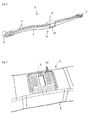
- Fig. 1 shows a suspension of a truck over 7.5 t, in which a spring 1 is connected in the form of a leaf spring 1 via U-bolts 2 with the axis 3 of the truck.
- the spring 1 has an elongated spring body 4 made of composite material, which has a rolled eye 5 at both longitudinal ends. About the eyes 5 of the spring body 4 is connected to the chassis 6 of the truck.
- both longitudinal ends may have an eye 5.
- a longitudinal end may be a rolled or molded, e.g. in the spring body 4 introduced, eye 5, whereas the other longitudinal end is substantially flat.
- the spring body 4 can be angled or bent in particular in the region of the flat longitudinal end.
- both ends may be substantially flat and possibly slightly cranked (without eye).
- the central region 7 of the spring body 4 has a greater base thickness, as the rest of the spring body 4, wherein in the central region 7 of the spring body 4, as in Fig. 2 can be seen, a recess 8 is provided.
- the recess 8 is designed as an elongated slot 8, which extends transversely to the longitudinal extent of the spring body 4.
- the larger base thickness of the spring body 4 in its central region 7 is achieved by an increase. In the embodiment shown, an increase on one side of the spring body can be seen. It can also be provided on the opposite side of a second increase.
- the regions of the spring body 4 adjoining the middle region 7 may, for example, have a height (base thickness) of approximately 64 mm.
- the increase in middle area 7 can each have an additional height of about 8 mm. If such elevations are provided on two opposite sides of the spring body 4, the middle region 7 with a larger base thickness can therefore have a height of approximately 80 mm.
- the central region 7 with greater base thickness may have a length of about 68 mm and a width of about 59.5 mm. These values can vary according to spring 1, depending on the embodiment.
- the slot 8 may have a length of about 47 mm and a width of about 16.5 mm.
- Fig. 5 an embodiment of a spring according to the invention is shown, in which on the surface of the spring body 4 fibers 9 are arranged, which extend substantially parallel to the longitudinal extent of the spring body 4 from the region of a longitudinal end to the region of the opposite longitudinal end of the spring body (longitudinal fibers 9).
- fibers 10 may be arranged on the surface of the middle region 7 of the spring body 4, which extend substantially transversely to the longitudinal extension of the spring body 4 (transverse fibers 10).
- the transverse fibers 10 may extend substantially parallel to the recess and be arranged on both longitudinal sides of the recess 8.
- Fig. 7 shows that on two opposite sides of the spring body per a recess 8 is provided, namely on the side of the spring body 4, which in use position to the axis 3 also has on the opposite side of the spring body 4.
- a cover 11 is arranged, which is a steel plate 11 in the illustrated embodiment.
- the cover 11 has, as in particular in the 8 and 9 shown, a projection 12 which is arranged in shape and size with the central region 7 of the spring body 4 Recess 8 corresponds and engages positively in the assembled state of the cover 11 in the recess 8 of the spring body 4.
- an intermediate piece 13 is disposed between the spring body 4 and the cover 11, which has a lower hardness than the spring body 4.
- the cover 11 has on the spring body 4 facing side a recess 14 which corresponds in shape and size with the intermediate piece 13, so that the intermediate piece 13 can be arranged in a form-fitting manner in the recess 14 of the cover 11 ( Fig. 8 ).
- the intermediate piece 13 has a recess 15 which corresponds in shape and size with the arranged in the central region 7 of the spring body 4 recess 8 and is arranged above the recess 8 in the mounted state.
- the projection 12 of the cover 11 penetrates the recess 15 in the mounted state (FIG. Fig. 9 ).
- Fig. 2 is exemplified the support area for the intermediate piece 13, which may be about 150 mm long and about 80 mm wide.
Abstract
Eine Radaufhängung eines Fahrzeuges, insbesondere eines mittelschweren oder schweren Lastkraftwagens weist eine Achse (3) und eine Feder (1) auf. Die Feder (1), insbesondere Blattfeder (1), weist einen länglichen Federkörper (4) mit zwei Längsenden und einem mittleren Bereich (7) auf, wobei der Federkörper (4) aus einem Verbundwerkstoff besteht. Der mittlere Bereich (7) des Federkörpers (4) weist eine größere Basisdicke auf, als der Rest des Federkörpers (4), wobei im mittleren Bereich (7) des Federkörpers (4) eine Vertiefung (8) vorgesehen ist.A suspension of a vehicle, in particular a medium or heavy truck has an axle (3) and a spring (1). The spring (1), in particular leaf spring (1), has an elongated spring body (4) with two longitudinal ends and a central region (7), wherein the spring body (4) consists of a composite material. The central region (7) of the spring body (4) has a greater base thickness than the rest of the spring body (4), wherein in the central region (7) of the spring body (4) has a recess (8) is provided.
Description
Die Erfindung betrifft eine Feder, insbesondere Blattfeder, für eine Radaufhängung eines Fahrzeuges, wobei die Feder einen länglichen Federkörper mit zwei Längsenden und einem mittleren Bereich aufweist und wobei der Federkörper aus einem Verbundwerkstoff besteht.The invention relates to a spring, in particular leaf spring, for a wheel suspension of a vehicle, wherein the spring has an elongate spring body with two longitudinal ends and a central region and wherein the spring body consists of a composite material.
Zudem betrifft die Erfindung eine Radaufhängung eines Fahrzeuges mit einer Achse und einer Feder.In addition, the invention relates to a suspension of a vehicle with an axle and a spring.
Darüber hinaus betrifft die Erfindung ein Fahrzeug, insbesondere ein mittelschweres oder schweres Lastkraftfahrzeug.Moreover, the invention relates to a vehicle, in particular a medium-weight or heavy truck.
Bei Kraftfahrzeugen wird zwischen Personenkraftwagen (PKW) und Lastkraftwagen (LKW) unterschieden, wobei die Anforderungen bezüglich der Federung bzw. der Radaufhängung aufgrund der zu transportierenden Lasten unterschiedlich sind. Bei LKW wird weiters zwischen leichten LKW ("LLKW", bis 7,5 t), mittelschweren LKW ("LKW", von 7,5 t bis 12 t) und schweren LKW ("SKW", ab 12 t) unterschieden, wobei die Anforderungen bezüglich der Federung bzw. der Radaufhängung wiederum aufgrund der zu transportierenden Lasten unterschiedlich sind.In motor vehicles, a distinction is made between cars (cars) and trucks (trucks), the requirements with regard to the suspension or the suspension being different due to the loads to be transported. For trucks, a distinction is made between light trucks ("light trucks", up to 7.5 t), medium trucks ("trucks", from 7.5 t to 12 t) and heavy trucks ("SKW", from 12 t), where the requirements regarding the suspension or the suspension in turn are different due to the loads to be transported.
Federn für eine Radaufhängung sind grundsätzlich derart ausgelegt, dass diese gute Fahreigenschaften erlauben und eine lange Lebensspanne haben, welche insbesondere von der Belastbarkeit und Haltbarkeit des Materials, aus welcher die Feder besteht, abhängt. Es ist die Verwendung von Federstahl und Verbundwerkstoff als Material für solche Federn bekannt.Springs for a suspension are basically designed so that they allow good handling characteristics and have a long life span, which depends in particular on the resilience and durability of the material from which the spring is made. It is the use of spring steel and composite material known as a material for such springs.
Weiterhin muss gewährleistet werden, dass die Feder, welche üblicherweise durch Schrauben mit der Achse verbunden ist, ausreichend (durch die Schrauben) fixiert ist. Bei der Verwendung von Federstahl können die Schrauben mit einem höheren Drehmoment befestigt werden, wodurch eine sichere Fixierung gewährleistet ist. Bei einer Feder aus Verbundwerkstoff wird üblicherweise ein geringeres Drehmoment angewendet, um zu vermeiden, dass der Verbundwerkstoff sonst beschädigt würde.Furthermore, it must be ensured that the spring, which is usually connected by screws to the axle, is sufficiently fixed (by the screws). When using spring steel, the screws can be fixed with a higher torque, which ensures a secure fixation. In a composite spring, a lower torque is usually applied to avoid that the composite would otherwise be damaged.
Der Erfindung liegt die Aufgabe zu Grunde, eine Feder sowie eine Radaufhängung eines Fahrzeuges zu ermöglichen, welche eine möglichst lange Lebensspanne hat, wobei insbesondere ein Verrutschen der Feder in Bezug auf die Achse stark vermindert bzw. vermieden wird. Zudem ist es eine Aufgabe der Erfindung, zu ermöglichen, dass die Feder mit einem angemessenen Drehmoment befestigt werden kann, ohne dass die Feder bricht. Insbesondere ist es eine Aufgabe der Erfindung, ein Verrutschen und/oder Brechen der Feder bei einer Kollision der Feder mit anderen Bauteilen der Radaufhängung zu vermeiden, was insbesondere bei einem Bremsvorgang passieren kann.The invention is based on the object to enable a spring and a suspension of a vehicle, which has a life span as long as possible, in particular slipping of the spring with respect to the axis is greatly reduced or avoided. In addition, it is an object of the invention to enable the spring to be fastened with adequate torque without the spring breaking. In particular, it is an object of the invention to avoid slippage and / or breakage of the spring in a collision of the spring with other components of the suspension, which can happen in particular during a braking operation.
Gelöst wird diese Aufgabe erfindungsgemäß mit einer Feder, welche die Merkmale des Anspruches 1 aufweist.This object is achieved according to the invention with a spring having the features of
Zudem wird die Aufgabe erfindungsgemäß mit einer Radaufhängung gelöst, welche die Merkmale des Anspruches 7 aufweist.In addition, the object is achieved with a suspension, which has the features of
Darüber hinaus wird die Aufgabe erfindungsgemäß mit einem Fahrzeug gelöst, welches die Merkmale des Anspruches 15 aufweist.In addition, the object is achieved with a vehicle having the features of
Bevorzugte und vorteilhafte Ausführungsformen der Erfindung sind Gegenstand der Unteransprüche.Preferred and advantageous embodiments of the invention are subject of the dependent claims.
Erfindungsgemäß ist vorgesehen, dass der mittlere Bereich des Federkörpers eine größere Basisdicke aufweist, als der Rest des Federkörpers, und dass im mittleren Bereich des Federkörpers eine Vertiefung vorgesehen ist. Somit ist es möglich, dass eine verhältnismäßig leichte Feder auch für mittelschwere und schwere LKW aus einem im Vergleich zu Federstahl leichteren Verbundwerkstoff hergestellt werden kann, wobei das Risiko eines Bruches der Feder und das Risiko, dass die Feder verrutscht, stark vermindert ist.According to the invention, it is provided that the central region of the spring body has a greater base thickness than the rest of the spring body, and that a depression is provided in the middle region of the spring body. Thus, it is possible that a relatively lightweight spring can be made for medium and heavy trucks from a lighter composite compared to spring steel, greatly reducing the risk of breakage of the spring and the risk of the spring slipping.
In einer bevorzugten Ausführungsform der Erfindung ist vorgesehen, dass die Vertiefung ein länglicher Schlitz ist, der im Wesentlichen quer zur Längserstreckung des Federkörpers verläuft.In a preferred embodiment of the invention it is provided that the recess is an elongated slot which extends substantially transversely to the longitudinal extension of the spring body.
Der Verbundwerkstoff der Feder weist vorteilhafterweise Glasfasern als Verstärkungselemente auf. Zusätzlich oder alternativ dazu weist der Verbundwerkstoff duroplastisches Harz oder thermoplastisches Harz auf. Insbesondere kann vorgesehen sein, dass der Verbundwerkstoff Polyurethan und/oder Polyamid und/oder Polyester aufweist.The composite of the spring advantageously has glass fibers as reinforcing elements. Additionally or alternatively, the composite comprises thermosetting resin or thermoplastic resin. In particular, it can be provided that the composite material comprises polyurethane and / or polyamide and / or polyester.
Im Rahmen der Erfindung ist es bevorzugt, wenn die Härte des Verbundwerkstoffes bei Verwendung von duroplastischem Material im Bereich von > 90 shore D liegt. Bei Verwendung von thermoplastischem Material kann dieses im Rahmen der Erfindung eine geringere Härte aufweisen als duroplastisches Material.In the context of the invention, it is preferable if the hardness of the composite material when using thermosetting material in the range of> 90 shore D. When using thermoplastic material, this may have a lower hardness in the context of the invention than thermosetting material.
Insbesondere ist es bevorzugt, wenn an der Oberfläche des Federkörpers Fasern, beispielsweise Glasfasern, angeordnet sind, die im Wesentlichen parallel zur Längserstreckung des Federkörpers, insbesondere vom Bereich eines Längsendes zum Bereich des gegenüberliegenden Längsendes des Federkörpers, verlaufen. Somit ist die Feder trotz ihres vergleichsweise geringen Gewichtes verstärkt, wobei das Risiko, dass die Feder bricht, weiterhin verringert ist und wobei einem Verrutschen der Feder entgegen gewirkt wird.In particular, it is preferred if fibers, for example glass fibers, are arranged on the surface of the spring body, which extend substantially parallel to the longitudinal extension of the spring body, in particular from the region of a longitudinal end to the region of the opposite longitudinal end of the spring body. Thus, despite its comparatively low weight, the spring is reinforced, and the risk of the spring breaking is further reduced, counteracting slippage of the spring.
Während einem Bremsvorgang wird ein erhöhter Druck auf die Feder ausgeübt. Um zu vermeiden, dass sich die im Wesentlichen parallel zur Längserstreckung des Federkörpers angeordneten Fasern dann lösen, ist in einer Ausführungsform der Erfindung vorteilhafterweise vorgesehen, dass an der Oberfläche des mittleren Bereichs des Federkörpers Fasern angeordnet sind, die im Wesentlichen quer zur Längserstreckung des Federkörpers verlaufen. In einer vorteilhaften Weiterbildung ist vorgesehen, dass die Fasern im Wesentlichen parallel zur Vertiefung verlaufen und vorzugsweise zu beiden Längsseiten der Vertiefung angeordnet sind.During a braking operation, an increased pressure is exerted on the spring. In order to avoid that the fibers arranged substantially parallel to the longitudinal extent of the spring body then come loose, in an embodiment of the invention it is advantageously provided that fibers are arranged on the surface of the central region of the spring body, which extend substantially transversely to the longitudinal extent of the spring body , In an advantageous development is provided in that the fibers run substantially parallel to the depression and are preferably arranged on both longitudinal sides of the depression.
Die im Wesentlichen parallel zur Längserstreckung des Federkörpers als auch die im Wesentlichen quer zur Längserstreckung des Federkörpers verlaufenden Fasern können direkt auf dem Federkörper angeordnet sein. Sie können auch indirekt auf dem Federkörper angeordnet sein, z.B. auf einer Zwischenschicht, wobei die Zwischenschicht direkt auf dem Federkörper angeordnet sein kann. Diese Fasern sind im Gegensatz zu Glasfasern des Verbundwerkstoffes nicht innerhalb des Federkörpers angeordnet.The substantially parallel to the longitudinal extent of the spring body and the substantially transverse to the longitudinal extent of the spring body fibers may be arranged directly on the spring body. They may also be arranged indirectly on the spring body, e.g. on an intermediate layer, wherein the intermediate layer can be arranged directly on the spring body. These fibers are not located within the spring body, unlike glass fibers of the composite material.
Erfindungsgemäß ist zudem eine Radaufhängung mit einer Achse und einer erfindungsgemäßen Feder vorgesehen. Es versteht sich, dass an der Achse zwei erfindungsgemäße Federn (für jedes Rad eine Feder) angeordnet sein können.According to the invention, a suspension with an axle and a spring according to the invention is also provided. It is understood that two springs according to the invention (one spring for each wheel) can be arranged on the axle.
In einer bevorzugten Ausführungsform der Erfindung ist die Vertiefung im Federkörper an der Seite des Federkörpers angeordnet, die in Einsatzposition zur Achse weist. Die Vertiefung kann zusätzlich auch an der gegenüberliegenden Seite des Federkörpers angeordnet sein.In a preferred embodiment of the invention, the recess in the spring body is arranged on the side of the spring body, which points in the use position to the axis. The recess may additionally be arranged on the opposite side of the spring body.
Das Verrutschen der Feder kann besonders wirksam vermieden werden, wenn im mittleren Bereich des Federkörpers ein Abdeckteil, insbesondere eine Platte, vorzugsweise eine Stahlplatte, angeordnet ist, der einen Vorsprung aufweist, der in Form und Größe mit der im mittleren Bereich des Federkörpers angeordneten Vertiefung korrespondiert. In einer besonders bevorzugten Ausführungsform greift der Vorsprung des Abdeckteils in die Vertiefung des Federkörpers ein.The slippage of the spring can be particularly effectively avoided if in the central region of the spring body, a cover, in particular a plate, preferably a steel plate is arranged, which has a projection which corresponds in shape and size with the arranged in the central region of the spring body depression , In a particularly preferred embodiment, the projection of the cover engages in the recess of the spring body.
Wenn der Abdeckteil, insbesondere die Stahlplatte, mit dem Federkörper kollidiert, besteht das Risiko, dass der Federkörper beschädigt wird. Dieses Risiko ist bei einem Bremsvorgang besonders erhöht. Insbesondere können die (Glas-)Fasern an der Oberfläche des Federkörpers beschädigt werden. Um dies zu vermeiden ist vorteilhafterweise vorgesehen, dass zwischen dem Federkörper und dem Abdeckteil ein Zwischenstück angeordnet ist. In einer besonders sicheren Ausführungsform der Erfindung ist vorgesehen, dass die Härte des Zwischenstücks geringer ist als die Härte des Federkörpers, insbesondere im Bereich zwischen 30 shore D und 90 shore D, wobei das Zwischenstück vorzugsweise aus Gummi oder aus thermoplastischem Werkstoff besteht.If the cover, in particular the steel plate collides with the spring body, there is a risk that the spring body is damaged. This risk is particularly increased during a braking process. In particular, the (glass) fibers on the surface of the spring body can be damaged. To avoid this, it is advantageously provided that an intermediate piece is arranged between the spring body and the cover part. In a particularly secure embodiment of the invention, it is provided that the hardness of the intermediate piece is less than the hardness of the spring body, in particular in the region between 30 shore D and 90 shore D, wherein the intermediate piece is preferably made of rubber or thermoplastic material.
Der Druck, der auf das Zwischenstück ausgeübt wird, kann zu einer Verspannung des Zwischenstückes führen, wobei sich die Länge und/oder die Breite des Zwischenstückes vergrößert. Um dies zu vermeiden weist der Abdeckteil in einer vorteilhaften Weiterbildung an der dem Federkörper zugewandten Seite eine Vertiefung auf, die in Form und Größe mit dem Zwischenstück korrespondiert, wobei insbesondere das Zwischenstück formschlüssig in der Vertiefung des Abdeckteils angeordnet ist.The pressure exerted on the intermediate piece can lead to a distortion of the intermediate piece, whereby the length and / or the width of the intermediate piece increases. To avoid this, the cover in an advantageous development on the side facing the spring body on a recess which corresponds in shape and size with the intermediate piece, wherein in particular the intermediate piece is arranged in a form-fitting manner in the recess of the cover.
Im Rahmen der Erfindung ist es weiterhin bevorzugt, dass der Abdeckteil derart ausgeführt und am Zwischenstück angeordnet ist, dass das Abdeckteil auch in Bereichen, in welchen kein Zwischenstück zwischen dem Federkörper und dem Abdeckteil vorgesehen ist, nicht mit dem Federkörper in Kontakt ist. Im Rahmen der Erfindung ist also vorgesehen, dass zwischen dem Abdeckteil und dem Federkörper ein Spalt vorgesehen ist. Somit wird vermieden, dass das Abdeckteil Druck auf den Federkörper ausübt.In the context of the invention, it is further preferred that the cover is designed and arranged on the intermediate piece, that the cover is not in areas in which no intermediate piece between the spring body and the cover is not in contact with the spring body. In the context of the invention it is thus provided that a gap is provided between the cover part and the spring body. Thus, it is avoided that the cover exerts pressure on the spring body.
Im Rahmen der Erfindung ist vorteilhafterweise vorgesehen, dass der Federkörper über U-Bolzen mit der Achse verbunden ist.In the context of the invention is advantageously provided that the spring body is connected via U-bolts with the axis.
Die erfindungsgemäße Feder und die erfindungsgemäße Radaufhängung sind sowohl für eine Radaufhängung für Vorderräder als auch für die Hinterräder eines Fahrzeuges verwendbar. Insbesondere ist der Einsatz bei einer Radaufhängung für Vorderräder von Vorteil, da bei einem Bremsvorgang die Radaufhängung für die Vorderräder besonders beansprucht wird und daher insbesondere das Brechen der Feder während dem Bremsvorgang vermieden wird.The spring according to the invention and the suspension according to the invention can be used both for a suspension for front wheels and for the rear wheels of a vehicle. In particular, the use in a suspension for front wheels is advantageous because during a braking operation, the suspension for the front wheels is particularly stressed and therefore in particular the breaking of the spring is avoided during braking.
Erfindung bezieht sich insbesondere auf eine Feder für eine Radaufhängung für Vorderräder eines Fahrzeuges.The invention relates in particular to a spring for a wheel suspension for front wheels of a vehicle.
Weitere Einzelheiten, Merkmale und Vorteile der Erfindung ergeben sich aus der nachstehenden Beschreibung unter Bezugnahme auf die angeschlossenen Zeichnungen, in welchen bevorzugte Ausführungsformen dargestellt sind.Further details, features and advantages of the invention will become apparent from the following description with reference to the accompanying drawings, in which preferred embodiments are shown.
Es zeigt:
- Fig. 1
- eine Ausführungsform einer erfindungsgemäßen Radaufhängung mit einer Ausführungsform einer erfindungsgemäßen Feder,
- Fig. 2
- einen Ausschnitt einer erfindungsgemäßen Feder im mittigen Bereich des Federkörpers,
- Fig. 3 und 4
- Ausschnitte einer erfindungsgemäßen Feder im mittigen Bereich des Federkörpers in Schnittansicht,
- Fig. 5
- eine Ausführungsform einer erfindungsgemäßen Feder mit teilweise angedeuteten Längsfasern,
- Fig. 6
- eine Ausführungsform einer erfindungsgemäßen Feder mit teilweise angedeuteten Querfasern im mittigen Bereich des Federkörpers,
- Fig. 7
- eine Ausführungsform eines Aufbaus aus Federkörper, Zwischenstück und Abdeckteil in Explosionsdarstellung,
- Fig. 8
- eine Ausführungsform von Zwischenstück und Abdeckteil in Explosionsdarstellung und
- Fig. 9
- das Zwischenstück und den Abdeckteil gemäß
Fig. 8 in zusammengebautem Zustand.
- Fig. 1
- An embodiment of a suspension according to the invention with an embodiment of a spring according to the invention,
- Fig. 2
- a detail of a spring according to the invention in the central region of the spring body,
- 3 and 4
- Cutouts of a spring according to the invention in the central region of the spring body in sectional view,
- Fig. 5
- an embodiment of a spring according to the invention with partially indicated longitudinal fibers,
- Fig. 6
- an embodiment of a spring according to the invention with partially indicated transverse fibers in the central region of the spring body,
- Fig. 7
- an embodiment of a construction of spring body, spacer and cover in an exploded view,
- Fig. 8
- an embodiment of spacer and cover in exploded view and
- Fig. 9
- the intermediate piece and the cover according to
Fig. 8 in assembled condition.
Je nach Art der Feder 1 können beide Längsenden ein Auge 5 aufweisen. Es kann auch ein Längsende ein gerolltes oder angeformtes, z.B. im Federkörper 4 eingebrachtes, Auge 5 aufweisen, wogegen das andere Längsende im Wesentlichen flach verläuft. In den zuletzt genannten Ausführungsformen kann der Federkörper 4 insbesondere im Bereich zum flach verlaufenden Längsende abgewinkelt bzw. abgekröpft sein. In einer anderen Ausführungsform können auch beide Enden im Wesentlichen flach und ggf. leicht abgekröpft (ohne Auge) verlaufen.Depending on the type of
Der mittlere Bereich 7 des Federkörpers 4 weist eine größere Basisdicke auf, als der Rest des Federkörpers 4, wobei im mittleren Bereich 7 des Federkörpers 4, wie in
In den Ausführungsformen gemäß
In
Um zu vermeiden, dass durch den Abdeckteil 11 Druck auf den weicheren Federkörper 4 ausgeübt wird, ist zwischen dem Federkörper 4 und dem Abdeckteil 11 ein Zwischenstück 13 angeordnet, das eine geringere Härte aufweist als der Federkörper 4. Der Abdeckteil 11 weist an der dem Federkörper 4 zugewandten Seite eine Vertiefung 14 auf, die in Form und Größe mit dem Zwischenstück 13 korrespondiert, so dass das Zwischenstück 13 formschlüssig in der Vertiefung 14 des Abdeckteils 11 angeordnet werden kann (
In
Claims (15)
Applications Claiming Priority (1)
| Application Number | Priority Date | Filing Date | Title |
|---|---|---|---|
| ATA751/2014A AT516366B1 (en) | 2014-10-06 | 2014-10-06 | Spring for suspension and suspension |
Publications (2)
| Publication Number | Publication Date |
|---|---|
| EP3006237A1 true EP3006237A1 (en) | 2016-04-13 |
| EP3006237B1 EP3006237B1 (en) | 2018-04-04 |
Family
ID=54291232
Family Applications (1)
| Application Number | Title | Priority Date | Filing Date |
|---|---|---|---|
| EP15450033.4A Active EP3006237B1 (en) | 2014-10-06 | 2015-09-24 | Spring for wheel suspension and wheel suspension |
Country Status (2)
| Country | Link |
|---|---|
| EP (1) | EP3006237B1 (en) |
| AT (1) | AT516366B1 (en) |
Cited By (5)
| Publication number | Priority date | Publication date | Assignee | Title |
|---|---|---|---|---|
| WO2017207801A1 (en) * | 2016-06-02 | 2017-12-07 | Muhr Und Bender Kg | Leaf spring arrangement and leaf spring |
| AT520413A1 (en) * | 2017-09-14 | 2019-03-15 | Hendrickson Comm Vehicle Sys Europe Gmbh | A leaf spring for use in conjunction with a suspension of a vehicle |
| DE102017218795A1 (en) | 2017-10-20 | 2019-04-25 | Ford Global Technologies, Llc | Axle |
| CN111791656A (en) * | 2020-06-30 | 2020-10-20 | 东风商用车有限公司 | Thickness-adjustable leaf spring backing plate |
| CN113059974A (en) * | 2020-01-02 | 2021-07-02 | 株洲时代新材料科技股份有限公司 | Composite plate spring protection device |
Families Citing this family (1)
| Publication number | Priority date | Publication date | Assignee | Title |
|---|---|---|---|---|
| DE102017206020B4 (en) | 2017-04-07 | 2022-09-08 | Ford Global Technologies, Llc | Leaf spring assembly for motor vehicles |
Citations (9)
| Publication number | Priority date | Publication date | Assignee | Title |
|---|---|---|---|---|
| DE2248006A1 (en) * | 1971-12-20 | 1973-07-05 | Aichi Steel Works Ltd | LEAF SPRING CONSTRUCTION |
| FR2437530A1 (en) * | 1978-09-28 | 1980-04-25 | Bekaert Sa Nv | ENERGY ABSORBING ELEMENT APPLICABLE IN PARTICULAR AS A SPRING BLADE |
| JPS5790434A (en) * | 1980-11-28 | 1982-06-05 | Hino Motors Ltd | Leaf spring for vehicle |
| EP0229471A1 (en) * | 1985-12-02 | 1987-07-22 | Ford Motor Company Limited | A leaf spring clamp assembly |
| JPS63225738A (en) * | 1987-03-12 | 1988-09-20 | Mazda Motor Corp | Leaf spring for vehicle |
| US20090256328A1 (en) * | 2008-04-15 | 2009-10-15 | Ashley Thomas Dudding | Isolated spring clamp group |
| US20130056900A1 (en) * | 2011-02-28 | 2013-03-07 | Benteler Sgl Gmbh & Co. Kg | Method for producing a leaf spring as a fiber composite component, and a leaf spring |
| US20130320644A1 (en) * | 2012-05-30 | 2013-12-05 | Hendrickson Usa, L.L.C. | Energy Storing Suspension Components Having Retention Recesses |
| WO2014145455A1 (en) * | 2013-03-15 | 2014-09-18 | Gordon Holdings, Inc. | Light weight composite leaf spring and method of making |
Family Cites Families (4)
| Publication number | Priority date | Publication date | Assignee | Title |
|---|---|---|---|---|
| US4611793A (en) * | 1984-06-21 | 1986-09-16 | Toyota Jidosha Kabushiki Kaisha | Leaf spring assembly for wheel suspension |
| US4598900A (en) * | 1984-06-25 | 1986-07-08 | Toyota Jidosha Kabushiki Kaisha | FRP leaf spring suspension |
| US4895350A (en) * | 1988-08-01 | 1990-01-23 | A. O. Smith Corporation | Axle mount construction for a fiber reinforced resin leaf spring |
| DE102009028895A1 (en) * | 2009-08-26 | 2011-03-03 | Zf Friedrichshafen Ag | Bearing device of a transverse leaf spring |
-
2014
- 2014-10-06 AT ATA751/2014A patent/AT516366B1/en active
-
2015
- 2015-09-24 EP EP15450033.4A patent/EP3006237B1/en active Active
Patent Citations (9)
| Publication number | Priority date | Publication date | Assignee | Title |
|---|---|---|---|---|
| DE2248006A1 (en) * | 1971-12-20 | 1973-07-05 | Aichi Steel Works Ltd | LEAF SPRING CONSTRUCTION |
| FR2437530A1 (en) * | 1978-09-28 | 1980-04-25 | Bekaert Sa Nv | ENERGY ABSORBING ELEMENT APPLICABLE IN PARTICULAR AS A SPRING BLADE |
| JPS5790434A (en) * | 1980-11-28 | 1982-06-05 | Hino Motors Ltd | Leaf spring for vehicle |
| EP0229471A1 (en) * | 1985-12-02 | 1987-07-22 | Ford Motor Company Limited | A leaf spring clamp assembly |
| JPS63225738A (en) * | 1987-03-12 | 1988-09-20 | Mazda Motor Corp | Leaf spring for vehicle |
| US20090256328A1 (en) * | 2008-04-15 | 2009-10-15 | Ashley Thomas Dudding | Isolated spring clamp group |
| US20130056900A1 (en) * | 2011-02-28 | 2013-03-07 | Benteler Sgl Gmbh & Co. Kg | Method for producing a leaf spring as a fiber composite component, and a leaf spring |
| US20130320644A1 (en) * | 2012-05-30 | 2013-12-05 | Hendrickson Usa, L.L.C. | Energy Storing Suspension Components Having Retention Recesses |
| WO2014145455A1 (en) * | 2013-03-15 | 2014-09-18 | Gordon Holdings, Inc. | Light weight composite leaf spring and method of making |
Cited By (7)
| Publication number | Priority date | Publication date | Assignee | Title |
|---|---|---|---|---|
| WO2017207801A1 (en) * | 2016-06-02 | 2017-12-07 | Muhr Und Bender Kg | Leaf spring arrangement and leaf spring |
| AT520413A1 (en) * | 2017-09-14 | 2019-03-15 | Hendrickson Comm Vehicle Sys Europe Gmbh | A leaf spring for use in conjunction with a suspension of a vehicle |
| DE102017218795A1 (en) | 2017-10-20 | 2019-04-25 | Ford Global Technologies, Llc | Axle |
| US10744835B2 (en) | 2017-10-20 | 2020-08-18 | Ford Global Technologies, Llc | Leaf spring suspension |
| DE102017218795B4 (en) * | 2017-10-20 | 2021-05-27 | Ford Global Technologies, Llc | Axle suspension |
| CN113059974A (en) * | 2020-01-02 | 2021-07-02 | 株洲时代新材料科技股份有限公司 | Composite plate spring protection device |
| CN111791656A (en) * | 2020-06-30 | 2020-10-20 | 东风商用车有限公司 | Thickness-adjustable leaf spring backing plate |
Also Published As
| Publication number | Publication date |
|---|---|
| AT516366B1 (en) | 2017-01-15 |
| AT516366A1 (en) | 2016-04-15 |
| EP3006237B1 (en) | 2018-04-04 |
Similar Documents
| Publication | Publication Date | Title |
|---|---|---|
| EP3006237B1 (en) | Spring for wheel suspension and wheel suspension | |
| EP3017211B1 (en) | Leaf spring and leaf spring assembly | |
| EP2545294B1 (en) | Leaf spring for motor vehicles | |
| EP2470387B1 (en) | Mounting device for a laterally orientated leafspring | |
| EP2801491B1 (en) | Transverse spring leaf system for a motor vehicle | |
| DE102011077336A1 (en) | Wheel suspension element comprising at least one support structure and a handlebar | |
| DE102013209648A1 (en) | Suspension for a vehicle | |
| DE102009017287A1 (en) | Axle construction for a vehicle, in particular for a commercial vehicle | |
| DE102010061649A1 (en) | Leaf spring element | |
| DE102017206020B4 (en) | Leaf spring assembly for motor vehicles | |
| EP3550171B1 (en) | Leaf spring for a vehicle and method of manufacturing such a leaf spring | |
| EP3113962B1 (en) | Spring-arm device | |
| EP3550172A1 (en) | Leaf spring holder for connecting a leaf spring with an axle and chassis provided with such a leaf spring holder | |
| DE102017215403A1 (en) | spring assembly | |
| DE102013203848A1 (en) | Drive axle for an industrial truck | |
| EP2976543A1 (en) | Helical compression spring arrangement | |
| DE102017218795B4 (en) | Axle suspension | |
| DE60129620T2 (en) | Suspension device for a carrying frame | |
| EP3230616B1 (en) | Spring for a vehicle | |
| DE102018206955B4 (en) | Leaf spring unit | |
| DE102016209689A1 (en) | Two-piece suspension unit | |
| DE102016209691A1 (en) | Two-piece suspension unit | |
| DE102019218062A1 (en) | Suspension device for suspending a chassis of a motor vehicle | |
| DE202016105784U1 (en) | Suspension suspension | |
| DE102009020099A1 (en) | Axle body i.e. front axle body, for use in motor vehicle i.e. commercial vehicle such as lorry, has recesses arranged in perpendicular area of middle axle body section extending in vehicle transverse axis direction in installation direction |
Legal Events
| Date | Code | Title | Description |
|---|---|---|---|
| PUAI | Public reference made under article 153(3) epc to a published international application that has entered the european phase |
Free format text: ORIGINAL CODE: 0009012 |
|
| AK | Designated contracting states |
Kind code of ref document: A1 Designated state(s): AL AT BE BG CH CY CZ DE DK EE ES FI FR GB GR HR HU IE IS IT LI LT LU LV MC MK MT NL NO PL PT RO RS SE SI SK SM TR |
|
| AX | Request for extension of the european patent |
Extension state: BA ME |
|
| 17P | Request for examination filed |
Effective date: 20161013 |
|
| RBV | Designated contracting states (corrected) |
Designated state(s): AL AT BE BG CH CY CZ DE DK EE ES FI FR GB GR HR HU IE IS IT LI LT LU LV MC MK MT NL NO PL PT RO RS SE SI SK SM TR |
|
| RAP1 | Party data changed (applicant data changed or rights of an application transferred) |
Owner name: HENDRICKSON COMMERCIAL VEHICLE SYSTEMS EUROPE GMBH |
|
| GRAP | Despatch of communication of intention to grant a patent |
Free format text: ORIGINAL CODE: EPIDOSNIGR1 |
|
| INTG | Intention to grant announced |
Effective date: 20171106 |
|
| GRAS | Grant fee paid |
Free format text: ORIGINAL CODE: EPIDOSNIGR3 |
|
| GRAA | (expected) grant |
Free format text: ORIGINAL CODE: 0009210 |
|
| AK | Designated contracting states |
Kind code of ref document: B1 Designated state(s): AL AT BE BG CH CY CZ DE DK EE ES FI FR GB GR HR HU IE IS IT LI LT LU LV MC MK MT NL NO PL PT RO RS SE SI SK SM TR |
|
| REG | Reference to a national code |
Ref country code: GB Ref legal event code: FG4D Free format text: NOT ENGLISH |
|
| REG | Reference to a national code |
Ref country code: CH Ref legal event code: EP |
|
| REG | Reference to a national code |
Ref country code: AT Ref legal event code: REF Ref document number: 985205 Country of ref document: AT Kind code of ref document: T Effective date: 20180415 |
|
| REG | Reference to a national code |
Ref country code: DE Ref legal event code: R096 Ref document number: 502015003721 Country of ref document: DE |
|
| REG | Reference to a national code |
Ref country code: IE Ref legal event code: FG4D Free format text: LANGUAGE OF EP DOCUMENT: GERMAN |
|
| REG | Reference to a national code |
Ref country code: NL Ref legal event code: MP Effective date: 20180404 |
|
| REG | Reference to a national code |
Ref country code: LT Ref legal event code: MG4D |
|
| REG | Reference to a national code |
Ref country code: FR Ref legal event code: PLFP Year of fee payment: 4 |
|
| PG25 | Lapsed in a contracting state [announced via postgrant information from national office to epo] |
Ref country code: NL Free format text: LAPSE BECAUSE OF FAILURE TO SUBMIT A TRANSLATION OF THE DESCRIPTION OR TO PAY THE FEE WITHIN THE PRESCRIBED TIME-LIMIT Effective date: 20180404 |
|
| PG25 | Lapsed in a contracting state [announced via postgrant information from national office to epo] |
Ref country code: SE Free format text: LAPSE BECAUSE OF FAILURE TO SUBMIT A TRANSLATION OF THE DESCRIPTION OR TO PAY THE FEE WITHIN THE PRESCRIBED TIME-LIMIT Effective date: 20180404 Ref country code: ES Free format text: LAPSE BECAUSE OF FAILURE TO SUBMIT A TRANSLATION OF THE DESCRIPTION OR TO PAY THE FEE WITHIN THE PRESCRIBED TIME-LIMIT Effective date: 20180404 Ref country code: LT Free format text: LAPSE BECAUSE OF FAILURE TO SUBMIT A TRANSLATION OF THE DESCRIPTION OR TO PAY THE FEE WITHIN THE PRESCRIBED TIME-LIMIT Effective date: 20180404 Ref country code: AL Free format text: LAPSE BECAUSE OF FAILURE TO SUBMIT A TRANSLATION OF THE DESCRIPTION OR TO PAY THE FEE WITHIN THE PRESCRIBED TIME-LIMIT Effective date: 20180404 Ref country code: PL Free format text: LAPSE BECAUSE OF FAILURE TO SUBMIT A TRANSLATION OF THE DESCRIPTION OR TO PAY THE FEE WITHIN THE PRESCRIBED TIME-LIMIT Effective date: 20180404 Ref country code: NO Free format text: LAPSE BECAUSE OF FAILURE TO SUBMIT A TRANSLATION OF THE DESCRIPTION OR TO PAY THE FEE WITHIN THE PRESCRIBED TIME-LIMIT Effective date: 20180704 Ref country code: BG Free format text: LAPSE BECAUSE OF FAILURE TO SUBMIT A TRANSLATION OF THE DESCRIPTION OR TO PAY THE FEE WITHIN THE PRESCRIBED TIME-LIMIT Effective date: 20180704 Ref country code: FI Free format text: LAPSE BECAUSE OF FAILURE TO SUBMIT A TRANSLATION OF THE DESCRIPTION OR TO PAY THE FEE WITHIN THE PRESCRIBED TIME-LIMIT Effective date: 20180404 |
|
| PG25 | Lapsed in a contracting state [announced via postgrant information from national office to epo] |
Ref country code: RS Free format text: LAPSE BECAUSE OF FAILURE TO SUBMIT A TRANSLATION OF THE DESCRIPTION OR TO PAY THE FEE WITHIN THE PRESCRIBED TIME-LIMIT Effective date: 20180404 Ref country code: HR Free format text: LAPSE BECAUSE OF FAILURE TO SUBMIT A TRANSLATION OF THE DESCRIPTION OR TO PAY THE FEE WITHIN THE PRESCRIBED TIME-LIMIT Effective date: 20180404 Ref country code: GR Free format text: LAPSE BECAUSE OF FAILURE TO SUBMIT A TRANSLATION OF THE DESCRIPTION OR TO PAY THE FEE WITHIN THE PRESCRIBED TIME-LIMIT Effective date: 20180705 Ref country code: LV Free format text: LAPSE BECAUSE OF FAILURE TO SUBMIT A TRANSLATION OF THE DESCRIPTION OR TO PAY THE FEE WITHIN THE PRESCRIBED TIME-LIMIT Effective date: 20180404 |
|
| PG25 | Lapsed in a contracting state [announced via postgrant information from national office to epo] |
Ref country code: PT Free format text: LAPSE BECAUSE OF FAILURE TO SUBMIT A TRANSLATION OF THE DESCRIPTION OR TO PAY THE FEE WITHIN THE PRESCRIBED TIME-LIMIT Effective date: 20180806 |
|
| REG | Reference to a national code |
Ref country code: DE Ref legal event code: R097 Ref document number: 502015003721 Country of ref document: DE |
|
| PG25 | Lapsed in a contracting state [announced via postgrant information from national office to epo] |
Ref country code: DK Free format text: LAPSE BECAUSE OF FAILURE TO SUBMIT A TRANSLATION OF THE DESCRIPTION OR TO PAY THE FEE WITHIN THE PRESCRIBED TIME-LIMIT Effective date: 20180404 Ref country code: EE Free format text: LAPSE BECAUSE OF FAILURE TO SUBMIT A TRANSLATION OF THE DESCRIPTION OR TO PAY THE FEE WITHIN THE PRESCRIBED TIME-LIMIT Effective date: 20180404 Ref country code: SK Free format text: LAPSE BECAUSE OF FAILURE TO SUBMIT A TRANSLATION OF THE DESCRIPTION OR TO PAY THE FEE WITHIN THE PRESCRIBED TIME-LIMIT Effective date: 20180404 Ref country code: RO Free format text: LAPSE BECAUSE OF FAILURE TO SUBMIT A TRANSLATION OF THE DESCRIPTION OR TO PAY THE FEE WITHIN THE PRESCRIBED TIME-LIMIT Effective date: 20180404 Ref country code: CZ Free format text: LAPSE BECAUSE OF FAILURE TO SUBMIT A TRANSLATION OF THE DESCRIPTION OR TO PAY THE FEE WITHIN THE PRESCRIBED TIME-LIMIT Effective date: 20180404 |
|
| PLBE | No opposition filed within time limit |
Free format text: ORIGINAL CODE: 0009261 |
|
| STAA | Information on the status of an ep patent application or granted ep patent |
Free format text: STATUS: NO OPPOSITION FILED WITHIN TIME LIMIT |
|
| PG25 | Lapsed in a contracting state [announced via postgrant information from national office to epo] |
Ref country code: IT Free format text: LAPSE BECAUSE OF FAILURE TO SUBMIT A TRANSLATION OF THE DESCRIPTION OR TO PAY THE FEE WITHIN THE PRESCRIBED TIME-LIMIT Effective date: 20180404 Ref country code: SM Free format text: LAPSE BECAUSE OF FAILURE TO SUBMIT A TRANSLATION OF THE DESCRIPTION OR TO PAY THE FEE WITHIN THE PRESCRIBED TIME-LIMIT Effective date: 20180404 |
|
| 26N | No opposition filed |
Effective date: 20190107 |
|
| PG25 | Lapsed in a contracting state [announced via postgrant information from national office to epo] |
Ref country code: MC Free format text: LAPSE BECAUSE OF FAILURE TO SUBMIT A TRANSLATION OF THE DESCRIPTION OR TO PAY THE FEE WITHIN THE PRESCRIBED TIME-LIMIT Effective date: 20180404 |
|
| REG | Reference to a national code |
Ref country code: CH Ref legal event code: PL |
|
| PG25 | Lapsed in a contracting state [announced via postgrant information from national office to epo] |
Ref country code: SI Free format text: LAPSE BECAUSE OF FAILURE TO SUBMIT A TRANSLATION OF THE DESCRIPTION OR TO PAY THE FEE WITHIN THE PRESCRIBED TIME-LIMIT Effective date: 20180404 |
|
| REG | Reference to a national code |
Ref country code: BE Ref legal event code: MM Effective date: 20180930 |
|
| REG | Reference to a national code |
Ref country code: IE Ref legal event code: MM4A |
|
| PG25 | Lapsed in a contracting state [announced via postgrant information from national office to epo] |
Ref country code: LU Free format text: LAPSE BECAUSE OF NON-PAYMENT OF DUE FEES Effective date: 20180924 |
|
| PG25 | Lapsed in a contracting state [announced via postgrant information from national office to epo] |
Ref country code: IE Free format text: LAPSE BECAUSE OF NON-PAYMENT OF DUE FEES Effective date: 20180924 |
|
| PG25 | Lapsed in a contracting state [announced via postgrant information from national office to epo] |
Ref country code: LI Free format text: LAPSE BECAUSE OF NON-PAYMENT OF DUE FEES Effective date: 20180930 Ref country code: CH Free format text: LAPSE BECAUSE OF NON-PAYMENT OF DUE FEES Effective date: 20180930 Ref country code: BE Free format text: LAPSE BECAUSE OF NON-PAYMENT OF DUE FEES Effective date: 20180930 |
|
| PG25 | Lapsed in a contracting state [announced via postgrant information from national office to epo] |
Ref country code: MT Free format text: LAPSE BECAUSE OF FAILURE TO SUBMIT A TRANSLATION OF THE DESCRIPTION OR TO PAY THE FEE WITHIN THE PRESCRIBED TIME-LIMIT Effective date: 20180404 |
|
| PG25 | Lapsed in a contracting state [announced via postgrant information from national office to epo] |
Ref country code: CY Free format text: LAPSE BECAUSE OF FAILURE TO SUBMIT A TRANSLATION OF THE DESCRIPTION OR TO PAY THE FEE WITHIN THE PRESCRIBED TIME-LIMIT Effective date: 20180404 Ref country code: MK Free format text: LAPSE BECAUSE OF NON-PAYMENT OF DUE FEES Effective date: 20180404 Ref country code: HU Free format text: LAPSE BECAUSE OF FAILURE TO SUBMIT A TRANSLATION OF THE DESCRIPTION OR TO PAY THE FEE WITHIN THE PRESCRIBED TIME-LIMIT; INVALID AB INITIO Effective date: 20150924 |
|
| PG25 | Lapsed in a contracting state [announced via postgrant information from national office to epo] |
Ref country code: IS Free format text: LAPSE BECAUSE OF FAILURE TO SUBMIT A TRANSLATION OF THE DESCRIPTION OR TO PAY THE FEE WITHIN THE PRESCRIBED TIME-LIMIT Effective date: 20180804 |
|
| GBPC | Gb: european patent ceased through non-payment of renewal fee |
Effective date: 20190924 |
|
| PG25 | Lapsed in a contracting state [announced via postgrant information from national office to epo] |
Ref country code: GB Free format text: LAPSE BECAUSE OF NON-PAYMENT OF DUE FEES Effective date: 20190924 |
|
| PGFP | Annual fee paid to national office [announced via postgrant information from national office to epo] |
Ref country code: FR Payment date: 20210921 Year of fee payment: 7 Ref country code: AT Payment date: 20210930 Year of fee payment: 7 |
|
| PGFP | Annual fee paid to national office [announced via postgrant information from national office to epo] |
Ref country code: TR Payment date: 20210923 Year of fee payment: 7 Ref country code: DE Payment date: 20210920 Year of fee payment: 7 |
|
| REG | Reference to a national code |
Ref country code: DE Ref legal event code: R119 Ref document number: 502015003721 Country of ref document: DE |
|
| REG | Reference to a national code |
Ref country code: AT Ref legal event code: MM01 Ref document number: 985205 Country of ref document: AT Kind code of ref document: T Effective date: 20220924 |
|
| PG25 | Lapsed in a contracting state [announced via postgrant information from national office to epo] |
Ref country code: FR Free format text: LAPSE BECAUSE OF NON-PAYMENT OF DUE FEES Effective date: 20220930 Ref country code: DE Free format text: LAPSE BECAUSE OF NON-PAYMENT OF DUE FEES Effective date: 20230401 Ref country code: AT Free format text: LAPSE BECAUSE OF NON-PAYMENT OF DUE FEES Effective date: 20220924 |