EP3006141A1 - Double-sided, indexable turning insert and turning tool - Google Patents
Double-sided, indexable turning insert and turning tool Download PDFInfo
- Publication number
- EP3006141A1 EP3006141A1 EP14188324.9A EP14188324A EP3006141A1 EP 3006141 A1 EP3006141 A1 EP 3006141A1 EP 14188324 A EP14188324 A EP 14188324A EP 3006141 A1 EP3006141 A1 EP 3006141A1
- Authority
- EP
- European Patent Office
- Prior art keywords
- double
- corner
- cutting edge
- major surface
- turning insert
- Prior art date
- Legal status (The legal status is an assumption and is not a legal conclusion. Google has not performed a legal analysis and makes no representation as to the accuracy of the status listed.)
- Granted
Links
Images

Classifications
-
- B—PERFORMING OPERATIONS; TRANSPORTING
- B23—MACHINE TOOLS; METAL-WORKING NOT OTHERWISE PROVIDED FOR
- B23B—TURNING; BORING
- B23B27/00—Tools for turning or boring machines; Tools of a similar kind in general; Accessories therefor
- B23B27/14—Cutting tools of which the bits or tips or cutting inserts are of special material
- B23B27/141—Specially shaped plate-like cutting inserts, i.e. length greater or equal to width, width greater than or equal to thickness
-
- B—PERFORMING OPERATIONS; TRANSPORTING
- B23—MACHINE TOOLS; METAL-WORKING NOT OTHERWISE PROVIDED FOR
- B23B—TURNING; BORING
- B23B2200/00—Details of cutting inserts
- B23B2200/04—Overall shape
- B23B2200/0471—Square
-
- B—PERFORMING OPERATIONS; TRANSPORTING
- B23—MACHINE TOOLS; METAL-WORKING NOT OTHERWISE PROVIDED FOR
- B23B—TURNING; BORING
- B23B2200/00—Details of cutting inserts
- B23B2200/08—Rake or top surfaces
- B23B2200/086—Rake or top surfaces with one or more grooves
- B23B2200/087—Rake or top surfaces with one or more grooves for chip breaking
-
- B—PERFORMING OPERATIONS; TRANSPORTING
- B23—MACHINE TOOLS; METAL-WORKING NOT OTHERWISE PROVIDED FOR
- B23B—TURNING; BORING
- B23B2200/00—Details of cutting inserts
- B23B2200/36—Other features of cutting inserts not covered by B23B2200/04 - B23B2200/32
- B23B2200/3627—Indexing
-
- B—PERFORMING OPERATIONS; TRANSPORTING
- B23—MACHINE TOOLS; METAL-WORKING NOT OTHERWISE PROVIDED FOR
- B23B—TURNING; BORING
- B23B2205/00—Fixation of cutting inserts in holders
- B23B2205/16—Shims
-
- B—PERFORMING OPERATIONS; TRANSPORTING
- B23—MACHINE TOOLS; METAL-WORKING NOT OTHERWISE PROVIDED FOR
- B23B—TURNING; BORING
- B23B27/00—Tools for turning or boring machines; Tools of a similar kind in general; Accessories therefor
- B23B27/14—Cutting tools of which the bits or tips or cutting inserts are of special material
- B23B27/16—Cutting tools of which the bits or tips or cutting inserts are of special material with exchangeable cutting bits or cutting inserts, e.g. able to be clamped
-
- B—PERFORMING OPERATIONS; TRANSPORTING
- B23—MACHINE TOOLS; METAL-WORKING NOT OTHERWISE PROVIDED FOR
- B23B—TURNING; BORING
- B23B27/00—Tools for turning or boring machines; Tools of a similar kind in general; Accessories therefor
- B23B27/14—Cutting tools of which the bits or tips or cutting inserts are of special material
- B23B27/16—Cutting tools of which the bits or tips or cutting inserts are of special material with exchangeable cutting bits or cutting inserts, e.g. able to be clamped
- B23B27/1603—Cutting tools of which the bits or tips or cutting inserts are of special material with exchangeable cutting bits or cutting inserts, e.g. able to be clamped with specially shaped plate-like exchangeable cutting inserts, e.g. chip-breaking groove
-
- B—PERFORMING OPERATIONS; TRANSPORTING
- B23—MACHINE TOOLS; METAL-WORKING NOT OTHERWISE PROVIDED FOR
- B23B—TURNING; BORING
- B23B27/00—Tools for turning or boring machines; Tools of a similar kind in general; Accessories therefor
- B23B27/14—Cutting tools of which the bits or tips or cutting inserts are of special material
- B23B27/16—Cutting tools of which the bits or tips or cutting inserts are of special material with exchangeable cutting bits or cutting inserts, e.g. able to be clamped
- B23B27/1603—Cutting tools of which the bits or tips or cutting inserts are of special material with exchangeable cutting bits or cutting inserts, e.g. able to be clamped with specially shaped plate-like exchangeable cutting inserts, e.g. chip-breaking groove
- B23B27/1607—Cutting tools of which the bits or tips or cutting inserts are of special material with exchangeable cutting bits or cutting inserts, e.g. able to be clamped with specially shaped plate-like exchangeable cutting inserts, e.g. chip-breaking groove characterised by having chip-breakers
-
- B—PERFORMING OPERATIONS; TRANSPORTING
- B23—MACHINE TOOLS; METAL-WORKING NOT OTHERWISE PROVIDED FOR
- B23B—TURNING; BORING
- B23B27/00—Tools for turning or boring machines; Tools of a similar kind in general; Accessories therefor
- B23B27/14—Cutting tools of which the bits or tips or cutting inserts are of special material
- B23B27/16—Cutting tools of which the bits or tips or cutting inserts are of special material with exchangeable cutting bits or cutting inserts, e.g. able to be clamped
- B23B27/1603—Cutting tools of which the bits or tips or cutting inserts are of special material with exchangeable cutting bits or cutting inserts, e.g. able to be clamped with specially shaped plate-like exchangeable cutting inserts, e.g. chip-breaking groove
- B23B27/1611—Cutting tools of which the bits or tips or cutting inserts are of special material with exchangeable cutting bits or cutting inserts, e.g. able to be clamped with specially shaped plate-like exchangeable cutting inserts, e.g. chip-breaking groove characterised by having a special shape
Definitions
- the present invention relates generally to double-sided turning inserts for turning operations and, more particularly, to indexable double-sided turning inserts for turning operations and a turning tool.
- a single-sided insert has four cutting edges at four corners of the insert, the two cutting edges adjacent the cutting edge that is performing a cutting operation are at a particularly increased risk of being damaged.
- the usefulness of having chipbreakers as well as large support surfaces imposes particular limitations on the number of cutting edges that can be provided on cutting inserts for use in heavy machining operations.
- a double-sided turning insert having a square shape with first and second major surfaces, and a side surface between them, comprises exactly four cutting edges, wherein each cutting edge is located only at corner portions of the turning insert and spaced from another cutting edge, the double-sided turning insert being provided with exactly two, diagonally located cutting edges on each major surface, the major surfaces being identical but rotated 90 degrees relative to each other.
- a double-sided turning insert for turning operations comprises a first major surface having a square basic shape with first, second, third, and fourth corners, a second major surface having a square basic shape with first, second, third, and fourth corners, and a side surface between the first major surface and the second major surface, the side surface including first, second, third, and fourth corners between the first, second, third, and fourth corners of the first major surface and the first, second, third, and fourth corners of the second major surface, respectively, and first, second, third, and fourth side surface portions, each side surface portion of the first, second, third, and fourth side surface portions being disposed between a respective pair of the first, second, third, and fourth corners.
- the insert comprises first, second, third, and fourth cutting edges and first, second, third, and fourth non-cutting edges
- the first cutting edge is formed by the first corner of the first major surface and first corner of the side surface
- the second cutting edge is formed by the second corner of the second major surface and the second corner of the side surface
- the third cutting edge is formed by the third corner of the first major surface and the third corner of the side surface
- the fourth cutting edge is formed by the fourth corner of the second major surface and the fourth corner of the side surface
- the first non-cutting edge is formed by the first corner of the second major surface and first corner of the side surface
- the second non-cutting edge is formed by the second corner of the first major surface and the second corner of the side surface
- the third non-cutting edge is formed by the third corner of the second major surface and the third corner of the side surface
- the fourth non-cutting edge is formed by the fourth corner of the first major surface and the
- a turning tool comprises a toolholder having a pocket and fastening means, a square and flat shim mounted in the pocket, said pocket having upstanding walls defining a bisector, a square and double-sided turning insert having chipbreaker structures and support surfaces on major surfaces thereof, the square turning insert being held against the flat shim by the fastening means, wherein the turning insert is provided with cutting edges only at alternating corners on opposite major surfaces, each chipbreaker structure at a major surface in contact with the flat shim are provided distant from the bisector.
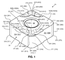
- a double-sided turning insert 21 that is particularly useful for turning operations is shown in FIG. 1 and includes a first surface or first major surface 23 having a square basic shape with first, second, third, and fourth corners 251, 252, 253, 254.
- the insert 21 also includes a second surface or second major surface 27 having a square basic shape with first, second, third, and fourth corners 291, 292, 293, 294.
- the second major surface 27 is identical to the first major surface 23 but rotated 90° along for example a plane depicted by the imaginary midline M in FIG. 6A .
- a double-sided turning insert with four cutting corners can be provided that is particularly useful in heavy machining with reduced risk of chips from a workpiece damaging an adjacent corner of the insert and thereby ruining the economic benefit of the four corners.
- the reference numbers shown in parentheses in FIG. 1 reflect the positions of the features identified by those reference numbers if the insert were turned over from the position shown, i.e., flipped 180° about a diagonal axis D1 or D2.
- a side or clearance surface 31 is disposed between the first major surface 23 and the second major surface 27.
- the side surface 31 includes first, second, third, and fourth corners 331, 332, 333, 334 between the first, second, third, and fourth corners 251, 252, 253, 254 of the first major surface 23 and the first, second, third, and fourth corners 291, 292, 293, 294 of the second major surface 27, respectively.
- the side surface 31 also includes first, second, third, and fourth side surface portions 351, 352, 353, 354. Each side surface portion of the first, second, third, and fourth side surface portions 351, 352, 353, 354 is disposed between a respective pair of the first, second, third, and fourth corners 291, 292, 293, 294 of the side surface 31.
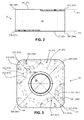
- a plane P1 of the first major surface 23 and a plane P2 of the second major surface 27 are parallel and are perpendicular to the side surface 31.
- the insert 21 comprises first, second, third, and fourth cutting edges 371, 372, 373, 374 and first, second, third, and fourth non-cutting edges 391, 392, 393, 394.
- the first cutting edge 371 is formed by at least the first corner 251 of the first major surface 23 and first corner 331 of the side surface 31.
- the second cutting edge 372 is formed by at least the second corner 292 of the second major surface 27 and the second corner 332 of the side surface 31.
- the third cutting edge 373 is formed by at least the third corner 253 of the first major surface 23 and the third corner 333 of the side surface 31.
- the fourth cutting edge 374 is formed by at least the fourth corner 294 of the second major surface 27 and the fourth corner 334 of the side surface 31.
- the first, second, third, and fourth cutting edges will ordinarily extend past the corners with which they are associated as seen with respect to the cutting edges 1371, 1372, 1373, and 1374 in FIG. 4B and the cutting edges 2371, 2372, 2373, and 2374 in FIG. 5B .
- the first non-cutting edge 391 is formed by the first corner 291 of the second major surface 27 and first corner 331 of the side surface 31.
- the second non-cutting edge 392 is formed by the second corner 252 of the first major surface 23 and the second corner 332 of the side surface 31.
- the third non-cutting edge 393 is formed by the third corner 293 of the second major surface 27 and the third corner 333 of the side surface 31.
- the fourth non-cutting edge 394 is formed by the fourth corner 254 of the first major surface 23 and the fourth corner 334 of the side surface 31.
- the first major surface 23 ordinarily comprises a first support surface 41 and the second major surface 27 ordinarily comprises a second support surface 43.
- the first and second support surfaces 41 and 43 can be planar surfaces.
- the first and second support surfaces 41 and 43 may not reach the associated cutting edges 371, 372, 373, 374 at the cutting corners 251, 292, 253, 294.
- the insert 21 can be provided with support surfaces of substantial size, which can facilitate providing enhanced stability.
- the side surface portions 351, 352, 353, 354 typically also function as support surfaces for the insert 21 and can be of substantial size to enhance stability.
- the first cutting edge 371 and the third cutting edge 373 can be disposed below the first support surface 41 in a direction toward the second support surface 43.
- the second cutting edge 372 and the fourth cutting edge 374 can be disposed below the second support surface 43 in a direction toward the first support surface 41.
- the insert 21 can comprise chipbreaker structures 451, 452, 453, 454 between the first cutting edge 371 and the first support surface 41, the second cutting edge 372 and the second support surface 43, the third cutting edge 373 and the first support surface, and the fourth cutting edge 374 and the second support surface.
- the chipbreaker structures 451, 452, 453, 454 between the cutting edges and the support surfaces can be in the form of a ridge or ridges rising from surfaces 471, 472, 473, 474 inward of the first, second, third, and fourth cutting edges 371, 372, 373,374.
- the chipbreaker structure may be symmetrical in top view relative to a diagonal axis D1, D2 of the insert ( FIG.3 ).
- Additional chipbreaker structures 491, 492, 493, 494 can also or alternatively be provided proximate the first, second, third, and fourth cutting edges 371, 372, 373, 374.
- the additional chipbreaker structures 491, 492, 493, 494 can be in the form of one or more protrusions proximate respective ones of the first, second, third, and fourth cutting edges 371, 372, 373, 374.
- Ridges of the chipbreaker structures 451, 452, 453, 455 can include convex curved portions 511, 512, 513, 514, respectively, centered on bisectors B1 and B2 between the first and third cutting edges and between the second and fourth cutting edges.
- the ridges can also include concave portions 531a, 531b, 532a, 532b, 533a, 533b, 534a, 534b on opposite sides of the bisectors B1 and B2.
- the chipbreaker structures can be provided without interfering with providing large supporting surfaces 41 and 43.
- chips from one of the cutting edges 371, 372, 373, 374 in use are unlikely to damage cutting edges that are not in use but are on adjacent corners.
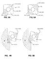
- the first and third cutting edges 1371 and 1373 each comprise no more than one quarter of a total length of a first edge 155 formed by the first major surface 123 and the side surface
- the second and fourth cutting edges 1372 and 1374 each comprise no more than one quarter of a total length of a second edge 157 formed by the second major surface 127 and the side surface.
- FIG. 4B shows the insert 121 performing a cutting operation on a workpiece W.
- the first and third cutting edges 2371 and 2373 each comprise more than one quarter of a total length of a first edge 255 formed by the first major surface 223 and the side surface
- the second and fourth cutting edges 2372 and 2374 each comprise more than one quarter of a total length of a second edge formed by the second major surface 227 and the side surface.
- FIG. 5B shows the insert 221 performing a cutting operation on a workpiece W.
- a turning insert with four cutting corners is provided that is particularly useful in heavy machining with reduced risk of chips from a workpiece damaging an adjacent corner of the insert and thereby ruining the economic benefit of the four corners.
- chips formed by the cutting corners 1371 or 1374 in FIG. 4B or cutting corners 2371 or 2374 in FIG. 5B are unlikely to damage the cutting corners 1373 or 1372, respectively, in FIG. 4B or 2373 or 2372, respectively, in FIG. 5B .
- a through hole 59 can extend between the first major surface 23 and the second major surface 27 and can be used to secure the insert to a toolholder ( FIGS. 6A-6C ), such as by a bolt or screw.
- First, second, third and fourth rake surfaces 611, 612, 613, 614 inward of the first, second, third, and fourth cutting edges 371, 372, 373, 374 can define acute angles with the side surface 31 if a sharper cutting edge is desired.
- the double-sided turning insert 21, 121, 221 has a square, preferably negative, basic shape with first and second major surfaces 23, 123, 223, 27, 127, 227 and a side surface 31 between them.
- the insert has exactly four cutting edges. Each cutting edge is located only at corner portions of the turning insert and spaced from another cutting edge.
- the double-sided turning insert 21 is provided with exactly two, diagonally located cutting edges 371, 372, 373, 374; 1371, 1372, 1373, 1374; 2371, 2372, 2373, 2374 on each major surface.
- the major surfaces 23, 27, are identical but rotated 90 degrees relative to each other, as seen in FIG. 3 .
- Each cutting edge 371, 372, 373, 374; 1371, 1372, 1373, 1374; 2371, 2372, 2373, 2374 may be formed at an intersection of a corner 251, 253, 292, 294 of a major surface and the side surface 31.
- a turning tool 20 comprising a double-sided turning insert 21 according to FIGS. 1-3 is shown in FIGS. 6A-6C .
- the turning tool comprises a conventional toolholder 22 having a pocket and fastening means, in this case a lever pin 26 manipulated via a screw 28.
- a square, flat shim 24 is mounted in the pocket.
- the pocket has upstanding walls 30, 32 defining a bisector B3.
- the upstanding walls may support the inactive clearance surfaces 31 of the turning insert.
- the square turning insert can be anyone of the inserts 21, 121, 221 and has chipbreaker structures 451, 452, 453, 454 and support surfaces 41, 43 on major surfaces 23, 27 thereof. The square turning insert is held against the flat shim by the fastening means.
- the turning insert 21 is provided with cutting edges 371 only at alternating corners on opposite major surfaces 23, 27.
- Each, preferably symmetrical, chipbreaker structure 451, 452, 453, 454 at a major surface in contact with the flat shim is provided distant from the bisector B3.
Landscapes
- Engineering & Computer Science (AREA)
- Mechanical Engineering (AREA)
- Milling Processes (AREA)
Abstract
Description
- The present invention relates generally to double-sided turning inserts for turning operations and, more particularly, to indexable double-sided turning inserts for turning operations and a turning tool.
- It is known to provide multiple cutting edges on cutting inserts to permit the inserts to be indexed to use a different one of the cutting edges when one becomes worn or damaged. It is also known to provide chipbreakers on cutting inserts to facilitate breaking chips that are formed from the workpiece as the cutting edge performs its cutting operation. For heavy machining operations, it is typically necessary to have large support surfaces on the insert for stability. Consequently, it is typical that an insert intended for heavy machining applications will be single sided, i.e., have all of its cutting edges on one side of the insert, while the other side of the insert will be used as a support surface. If the cutting edges on the one side of the insert are too close to one another, chips formed from the workpiece by one cutting edge in use can damage adjacent cutting edges. For example, if a single-sided insert has four cutting edges at four corners of the insert, the two cutting edges adjacent the cutting edge that is performing a cutting operation are at a particularly increased risk of being damaged. The usefulness of having chipbreakers as well as large support surfaces imposes particular limitations on the number of cutting edges that can be provided on cutting inserts for use in heavy machining operations.
- It is desirable to provide an indexable double-sided turning insert with chipbreakers, large supporting surfaces, and a large number of cutting edges that can be used with a reduced risk of damage to ones of the cutting edges that are not in use.
- According to an aspect of the present invention, a double-sided turning insert having a square shape with first and second major surfaces, and a side surface between them, comprises exactly four cutting edges, wherein each cutting edge is located only at corner portions of the turning insert and spaced from another cutting edge, the double-sided turning insert being provided with exactly two, diagonally located cutting edges on each major surface, the major surfaces being identical but rotated 90 degrees relative to each other.
- According to the aspect of the present invention, a double-sided turning insert for turning operations comprises a first major surface having a square basic shape with first, second, third, and fourth corners, a second major surface having a square basic shape with first, second, third, and fourth corners, and a side surface between the first major surface and the second major surface, the side surface including first, second, third, and fourth corners between the first, second, third, and fourth corners of the first major surface and the first, second, third, and fourth corners of the second major surface, respectively, and first, second, third, and fourth side surface portions, each side surface portion of the first, second, third, and fourth side surface portions being disposed between a respective pair of the first, second, third, and fourth corners. A plane of the first major surface and a plane of the second major surface are parallel and are perpendicular to the side surface, the insert comprises first, second, third, and fourth cutting edges and first, second, third, and fourth non-cutting edges, the first cutting edge is formed by the first corner of the first major surface and first corner of the side surface, the second cutting edge is formed by the second corner of the second major surface and the second corner of the side surface, the third cutting edge is formed by the third corner of the first major surface and the third corner of the side surface, and the fourth cutting edge is formed by the fourth corner of the second major surface and the fourth corner of the side surface, and the first non-cutting edge is formed by the first corner of the second major surface and first corner of the side surface, the second non-cutting edge is formed by the second corner of the first major surface and the second corner of the side surface, the third non-cutting edge is formed by the third corner of the second major surface and the third corner of the side surface, and the fourth non-cutting edge is formed by the fourth corner of the first major surface and the fourth corner of the side surface.
- According to another aspect of the present invention, a turning tool comprises a toolholder having a pocket and fastening means, a square and flat shim mounted in the pocket, said pocket having upstanding walls defining a bisector, a square and double-sided turning insert having chipbreaker structures and support surfaces on major surfaces thereof, the square turning insert being held against the flat shim by the fastening means, wherein the turning insert is provided with cutting edges only at alternating corners on opposite major surfaces, each chipbreaker structure at a major surface in contact with the flat shim are provided distant from the bisector.
- With such an insert and tool it is possible to provide a sturdy indexable insert with four cutting edges that can each perform a turning operation with minimal risk of damage to the cutting edges that are not in use.
- The features and advantages of the present invention are well understood by reading the following detailed description in conjunction with the drawings in which like numerals indicate similar elements and in which:
-
FIG. 1 is a perspective view of a double-sided turning insert according to an aspect of the present invention; -
FIG. 2 is a side view of the double-sided turning insert ofFIG. 1 ; -
FIG. 3 is a top view of the double-sided turning insert ofFIG. 1 ; -
FIG. 4A is a top view of a double-sided turning insert according to an aspect of the present invention, andFIG. 4B is a top view of the double-sided turning insert ofFIG. 4A performing a cutting operation; and -
FIG. 5A is a top view of a double-sided turning insert according to an aspect of the present invention, andFIG. 5B is a top view of the double-sided turning insert ofFIG. 5A performing a cutting operation. -
FIG. 6A is a perspective, exploded view of the double-sided turning insert according toFIGS. 1-3 and a toolholder. -
FIG. 6B is a perspective view of the double-sided turning insert mounted to the toolholder. -
FIG. 6C is a perspective view from below of the double-sided turning insert mounted to the toolholder. - A double-sided turning insert 21 that is particularly useful for turning operations is shown in
FIG. 1 and includes a first surface or firstmajor surface 23 having a square basic shape with first, second, third, andfourth corners insert 21 also includes a second surface or secondmajor surface 27 having a square basic shape with first, second, third, andfourth corners major surface 27 is identical to the firstmajor surface 23 but rotated 90° along for example a plane depicted by the imaginary midline M inFIG. 6A . In this way, a double-sided turning insert with four cutting corners can be provided that is particularly useful in heavy machining with reduced risk of chips from a workpiece damaging an adjacent corner of the insert and thereby ruining the economic benefit of the four corners. The reference numbers shown in parentheses inFIG. 1 reflect the positions of the features identified by those reference numbers if the insert were turned over from the position shown, i.e., flipped 180° about a diagonal axis D1 or D2. - A side or
clearance surface 31 is disposed between the firstmajor surface 23 and the secondmajor surface 27. Theside surface 31 includes first, second, third, andfourth corners fourth corners major surface 23 and the first, second, third, andfourth corners major surface 27, respectively. Theside surface 31 also includes first, second, third, and fourthside surface portions side surface portions fourth corners side surface 31. - As seen in
FIG. 2 , a plane P1 of the firstmajor surface 23 and a plane P2 of the secondmajor surface 27 are parallel and are perpendicular to theside surface 31. - Referring to
FIGS. 1 and3 , theinsert 21 comprises first, second, third, andfourth cutting edges edges - The
first cutting edge 371 is formed by at least thefirst corner 251 of the firstmajor surface 23 andfirst corner 331 of theside surface 31. Thesecond cutting edge 372 is formed by at least thesecond corner 292 of the secondmajor surface 27 and thesecond corner 332 of theside surface 31. Thethird cutting edge 373 is formed by at least thethird corner 253 of the firstmajor surface 23 and thethird corner 333 of theside surface 31. Thefourth cutting edge 374 is formed by at least thefourth corner 294 of the secondmajor surface 27 and thefourth corner 334 of theside surface 31. The first, second, third, and fourth cutting edges will ordinarily extend past the corners with which they are associated as seen with respect to thecutting edges FIG. 4B and thecutting edges FIG. 5B . - The first
non-cutting edge 391 is formed by thefirst corner 291 of the secondmajor surface 27 andfirst corner 331 of theside surface 31. The secondnon-cutting edge 392 is formed by thesecond corner 252 of the firstmajor surface 23 and thesecond corner 332 of theside surface 31. The thirdnon-cutting edge 393 is formed by thethird corner 293 of the secondmajor surface 27 and thethird corner 333 of theside surface 31. The fourthnon-cutting edge 394 is formed by thefourth corner 254 of the firstmajor surface 23 and thefourth corner 334 of theside surface 31. - The first
major surface 23 ordinarily comprises afirst support surface 41 and the secondmajor surface 27 ordinarily comprises asecond support surface 43. As illustrated, the first andsecond support surfaces second support surfaces cutting edges cutting corners insert 21 can be provided with support surfaces of substantial size, which can facilitate providing enhanced stability. Theside surface portions insert 21 and can be of substantial size to enhance stability. - As seen in
FIGS. 1 and2 , thefirst cutting edge 371 and thethird cutting edge 373 can be disposed below thefirst support surface 41 in a direction toward thesecond support surface 43. The secondcutting edge 372 and thefourth cutting edge 374 can be disposed below thesecond support surface 43 in a direction toward thefirst support surface 41. - The
insert 21 can comprisechipbreaker structures first cutting edge 371 and thefirst support surface 41, thesecond cutting edge 372 and thesecond support surface 43, thethird cutting edge 373 and the first support surface, and thefourth cutting edge 374 and the second support surface. Thechipbreaker structures surfaces - The chipbreaker structure may be symmetrical in top view relative to a diagonal axis D1, D2 of the insert (
FIG.3 ). -
Additional chipbreaker structures additional chipbreaker structures - Ridges of the
chipbreaker structures curved portions concave portions - Because the cutting edges 371, 372, 373, 374 are provided at alternating
corners opposite sides surfaces insert 21 is used in a cutting operation, chips from one of the cutting edges 371, 372, 373, 374 in use are unlikely to damage cutting edges that are not in use but are on adjacent corners. - In one form of
insert 121 according to an aspect of the present invention seen inFIGS. 4A and 4B , the first andthird cutting edges first edge 155 formed by the firstmajor surface 123 and the side surface, and the second andfourth cutting edges second edge 157 formed by the secondmajor surface 127 and the side surface.FIG. 4B shows theinsert 121 performing a cutting operation on a workpiece W. - In another form of
insert 221 according to another aspect of the present invention seen inFIGS. 5A and 5B , the first andthird cutting edges first edge 255 formed by the firstmajor surface 223 and the side surface, and the second andfourth cutting edges major surface 227 and the side surface.FIG. 5B shows theinsert 221 performing a cutting operation on a workpiece W. - In all of the illustrated double-sided turning inserts 21, 121, and 221, a turning insert with four cutting corners is provided that is particularly useful in heavy machining with reduced risk of chips from a workpiece damaging an adjacent corner of the insert and thereby ruining the economic benefit of the four corners. As seen in
FIGS. 4B and 5B , for example, chips formed by the cuttingcorners FIG. 4B or cuttingcorners FIG. 5B are unlikely to damage thecutting corners FIG. 4B or 2373 or 2372, respectively, inFIG. 5B . - As seen in
FIGS. 1-3 , a throughhole 59 can extend between the firstmajor surface 23 and the secondmajor surface 27 and can be used to secure the insert to a toolholder (FIGS. 6A-6C ), such as by a bolt or screw. First, second, third and fourth rake surfaces 611, 612, 613, 614 inward of the first, second, third, and fourth cutting edges 371, 372, 373, 374 can define acute angles with theside surface 31 if a sharper cutting edge is desired. - Stated another way, the double-
sided turning insert major surfaces side surface 31 between them. The insert has exactly four cutting edges. Each cutting edge is located only at corner portions of the turning insert and spaced from another cutting edge. The double-sided turning insert 21 is provided with exactly two, diagonally located cuttingedges major surfaces FIG. 3 . Eachcutting edge corner side surface 31. - A turning
tool 20 comprising a double-sided turning insert 21 according toFIGS. 1-3 is shown inFIGS. 6A-6C . The turning tool comprises aconventional toolholder 22 having a pocket and fastening means, in this case alever pin 26 manipulated via ascrew 28. A square,flat shim 24 is mounted in the pocket. The pocket hasupstanding walls inserts chipbreaker structures major surfaces insert 21 is provided with cuttingedges 371 only at alternating corners on oppositemajor surfaces chipbreaker structure - In the present application, the use of terms such as "including" is open-ended and is intended to have the same meaning as terms such as "comprising" and not preclude the presence of other structure, material, or acts. Similarly, though the use of terms such as "can" or "may" is intended to be open-ended and to reflect that structure, material, or acts are not necessary, the failure to use such terms is not intended to reflect that structure, material, or acts are essential. To the extent that structure, material, or acts are presently considered to be essential, they are identified as such. The terms "major" and "minor" refer to sizes, areas, lengths, etc. and the expression "square basic shape" is best explained by
FIG. 3 as perceived by the skilled person. - While this invention has been illustrated and described in accordance with a preferred embodiment, it is recognized that variations and changes may be made therein without departing from the invention as set forth in the claims.
Claims (17)
- A double-sided turning insert (21, 121, 221) having a square basic shape with first and second major surfaces (23, 123, 223, 27, 127, 227) and a side surface (31) between them, the insert having exactly four cutting edges, characterized in that each cutting edge is located only at corner portions of the turning insert and spaced from another cutting edge, in that the double-sided turning insert (21) is provided with exactly two, diagonally located cutting edges (371, 372, 373, 374; 1371, 1372, 1373, 1374; 2371, 2372, 2373, 2374) on each major surface and in that the major surfaces (23, 27) are identical but rotated 90 degrees relative to each other.
- The double-sided turning insert as set forth in claim 1, wherein each cutting edge (371, 372, 373, 374; 1371, 1372, 1373, 1374; 2371, 2372, 2373, 2374) is formed at an intersection of a corner (251, 253, 292,294) of a major surface and the side surface (31).
- The double-sided turning insert (21, 121, 221) as set forth in claim 1 or 2, wherein
the first major surface (23, 123, 223) has a square basic shape with first, second, third, and fourth corners (251, 252, 253, 254),
the second major surface (27, 127, 227) has a square basic shape with first, second, third, and fourth corners (291, 292, 293, 294),
the side surface (31) between the first major surface (23, 123, 223) and the second major surface (27, 127, 227), the side surface (31) including first, second, third, and fourth corners (331, 332, 333, 334) between the first, second, third, and fourth corners (251, 252, 253, 254) of the first major surface (23, 123, 223) and the first, second, third, and fourth corners (291, 292, 293, 294) of the second major surface (27, 127, 227), respectively, and first, second, third, and fourth side surface portions, each side surface portion of the first, second, third, and fourth side surface portions being disposed between a respective pair of the first, second, third, and fourth corners (331, 332, 333, 334) of the side surface (31),
wherein
a plane (P1) of the first major surface (23, 123, 223) and a plane (P2) of the second major surface (27, 127, 227) are parallel and are perpendicular to the side surface (31),
the insert (21) comprises first, second, third, and fourth cutting edges (371, 372, 373, 374; 1371, 1372, 1373, 1374; 2371, 2372, 2373, 2374) and first, second, third, and fourth non-cutting edges (391, 392, 393, 394),
the first cutting edge (371; 1371; 2371) is formed by at least the first corner (251) of the first major surface (23, 123, 223) and a first corner (331) of the side surface (31), the second cutting edge (372; 1372; 2372) is formed by at least the second corner (292) of the second major surface (27, 127, 227) and the second corner (332) of the side surface (31), the third cutting edge (373; 1373; 2373) is formed by at least the third corner (253) of the first major surface (23, 123, 223) and the third corner of the side surface (31), and the fourth cutting edge (374; 1374; 2374) is formed by at least the fourth corner (294) of the second major surface (27, 127, 227) and the fourth corner (334) of the side surface (31), and
the first non-cutting edge (391) is formed by the first corner (291) of the second major surface (27, 127, 227) and first corner (331) of the side surface (31), the second non-cutting edge (392) is formed by the second corner (252) of the first major surface (23, 123, 223) and the second corner (332) of the side surface (31), the third non-cutting edge (393) is formed by the third corner (292) of the second major surface (27, 127, 227) and the third corner (333) of the side surface (31), and the fourth non-cutting edge (394) is formed by the fourth corner (254) of the first major surface (23, 123, 223) and the fourth corner (334) of the side surface (31). - The double-sided turning insert as set forth in any of claims 1-3, wherein the first major surface (23, 123, 223) comprises a first support surface (41) and the second major surface (27, 127, 227) comprises a second support surface (43).
- The double-sided turning insert as set forth in claim 4, wherein the first and second support surfaces (41 and 43) are planar surfaces.
- The double-sided turning insert as set forth in any of claims 4-5, wherein the first cutting edge (371) and the third cutting edge (373) are disposed below the first support surface (41) in a direction toward the second support surface (43), and the second cutting edge (372) and the fourth cutting edge (374) are disposed below the second support surface (43) in a direction toward the first support surface (41).
- The double-sided turning insert as set forth in any of claims 4-6, comprising chipbreaker structures (451, 452, 453, 454) between the first cutting edge (371) and the first support surface (41), the second cutting edge (372) and the second support surface (43), the third cutting edge (373) and the first support surface (41), and the fourth cutting edge (374) and the second support surface (43).
- The double-sided turning insert as set forth in any of claims 1-7, comprising chipbreaker structures (451, 452, 453, 454) proximate the first, second, third, and fourth cutting edges (371, 372,373,374).
- The double-sided turning insert as set forth in any of claims 1-8, comprising chipbreaker structures (491, 492, 493, 494) comprising one or more protrusions proximate respective ones of the first, second, third, and fourth cutting edges (371, 372, 373, 374).
- The double-sided turning insert as set forth in any of claims 1-9, comprising chipbreaker structures (451, 452, 453, 454) comprising ridges proximate respective ones of the first, second, third, and fourth cutting edges (371, 372, 373, 374).
- The double-sided turning insert as set forth in claim 10, wherein the ridges include convex curved portions (511, 512, 513, 514) centered on bisectors (B1, B2) between the first and third cutting edges (371, 373) and between the second and fourth cutting edges (372, 374).
- The double-sided turning insert as set forth in any of claims 10-11, wherein the ridges include concave portions (531a, 531b, 532a, 532b, 533a, 533b, 534a, 534b) on opposite sides of bisectors (B1, B2) between the first and third cutting edges (371, 373) and between the second and fourth cutting edges (372, 374).
- The double-sided turning insert (21, 121) as set forth in any of claims 1-12, wherein the first and third cutting edges (371, 373; 1371, 1373) each comprise no more than one quarter of a total length of a first edge (155) formed by the first major surface (23, 123) and the side surface (31), and the second and fourth cutting edges (372, 374; 1372, 1374) each comprise no more than one quarter of a total length of a second edge (157) formed by the second major surface (27, 127) and the side surface (31).
- The double-sided turning insert (221) as set forth in any of claims 1-12, wherein the first and third cutting edges (2371, 2373) each comprise more than one quarter of a total length of a first edge (255) formed by the first major surface (223) and the side surface, and the second and fourth cutting edges (2372, 2374) each comprise more than one quarter of a total length of a second edge (257) formed by the second major surface (227) and the side surface.
- The double-sided turning insert as set forth in any of claims 1-14, comprising first, second, third, and fourth rake surfaces (611, 612, 613, 614) inward of the first, second, third, and fourth cutting edges (371, 372, 373, 374), the first, second, third, and fourth rake surfaces (611, 612, 613, 614) defining acute angles with the side surface (31).
- The double-sided turning insert as set forth in any of claims 1-15, wherein the insert comprises chipbreaker structures (451, 452, 453, 454) between the first cutting edge (371) and the first support surface (41), the second cutting edge (372) and the second support surface (43), the third cutting edge (373) and the first support surface, and the fourth cutting edge (374) and the second support surface, the chipbreaker structures (451, 452, 453, 454) being symmetrical relative to a diagonal axis (D1, D2) of the insert.
- A turning tool comprising;
a toolholder (22) having a pocket and fastening means (26, 28), a square and flat shim (24) mounted in the pocket, said pocket having upstanding walls (30, 32) defining a bisector (B3),
a square, double-sided turning insert (21, 121, 221) having chipbreaker structures (451, 452, 453, 454) and support surfaces (41, 43) on major surfaces (23, 27) thereof,
the square turning insert being held against the flat shim by the fastening means,
characterized in that the turning insert (21) is provided with cutting edges (371) only at alternating corners on opposite major surfaces (23, 27), and in that each chipbreaker structure (451, 452, 453, 454) at a major surface (23, 27) in contact with the flat shim is provided distant from the bisector (B3).
Priority Applications (3)
| Application Number | Priority Date | Filing Date | Title |
|---|---|---|---|
| EP14188324.9A EP3006141B1 (en) | 2014-10-09 | 2014-10-09 | Double-sided, indexable turning insert and turning tool |
| PCT/EP2015/071933 WO2016055276A1 (en) | 2014-10-09 | 2015-09-24 | Double-sided, indexable turning insert and turning tool |
| US15/517,588 US10335861B2 (en) | 2014-10-09 | 2015-09-24 | Double-sided, indexable turning insert and turning tool |
Applications Claiming Priority (1)
| Application Number | Priority Date | Filing Date | Title |
|---|---|---|---|
| EP14188324.9A EP3006141B1 (en) | 2014-10-09 | 2014-10-09 | Double-sided, indexable turning insert and turning tool |
Publications (2)
| Publication Number | Publication Date |
|---|---|
| EP3006141A1 true EP3006141A1 (en) | 2016-04-13 |
| EP3006141B1 EP3006141B1 (en) | 2021-09-29 |
Family
ID=51662002
Family Applications (1)
| Application Number | Title | Priority Date | Filing Date |
|---|---|---|---|
| EP14188324.9A Active EP3006141B1 (en) | 2014-10-09 | 2014-10-09 | Double-sided, indexable turning insert and turning tool |
Country Status (3)
| Country | Link |
|---|---|
| US (1) | US10335861B2 (en) |
| EP (1) | EP3006141B1 (en) |
| WO (1) | WO2016055276A1 (en) |
Cited By (4)
| Publication number | Priority date | Publication date | Assignee | Title |
|---|---|---|---|---|
| CN107138753A (en) * | 2017-07-04 | 2017-09-08 | 贵州大学 | A kind of microflute carbide-tipped lathe tool piece for cutting GH4169 alloy |
| CN107138752A (en) * | 2017-07-04 | 2017-09-08 | 贵州大学 | A kind of coated carbides rake face comb teeth shape microflute lathe tool of cutting 40CrMnMo |
| US20190160556A1 (en) * | 2017-11-29 | 2019-05-30 | Iscar, Ltd. | Double-sided cutting insert having orientation-assisting clamping recesses and cutting tool |
| US20230166336A1 (en) * | 2020-03-09 | 2023-06-01 | Muri Invest & Management Ug | Cutting tool and distance compensating element for positioning reground cutting inserts in a cutting tool |
Families Citing this family (7)
| Publication number | Priority date | Publication date | Assignee | Title |
|---|---|---|---|---|
| CN107206506A (en) * | 2015-02-24 | 2017-09-26 | 株式会社泰珂洛 | cutting tool |
| JP6717939B2 (en) * | 2016-06-17 | 2020-07-08 | 京セラ株式会社 | Manufacturing method of cutting insert, cutting tool, and cut product |
| EP3260225B1 (en) * | 2016-06-20 | 2022-11-30 | Sandvik Intellectual Property AB | Turning insert |
| WO2018025723A1 (en) * | 2016-08-03 | 2018-02-08 | 京セラ株式会社 | Cutting insert, cutting tool, and method for manufacturing cut workpiece |
| CN112809033B (en) * | 2020-12-30 | 2024-01-30 | 贵州大学 | Microstructure hard alloy turning blade for cutting AISI201 |
| JP7003388B1 (en) | 2021-04-28 | 2022-01-20 | 株式会社タンガロイ | Cutting tools |
| CN119053398A (en) | 2022-06-28 | 2024-11-29 | 山高刀具公司 | Cutting tool |
Citations (5)
| Publication number | Priority date | Publication date | Assignee | Title |
|---|---|---|---|---|
| GB1419743A (en) * | 1973-03-15 | 1975-12-31 | Carmet Co | Cutting inserts suitable for metal cutting machine tools |
| JPH0569206A (en) * | 1991-05-23 | 1993-03-23 | Mitsubishi Materials Corp | Throwaway cutting tool |
| US6929428B1 (en) * | 1999-06-16 | 2005-08-16 | Sandvik Ab | Cutting insert and cutting insert holder therefor |
| WO2006137050A1 (en) * | 2005-06-22 | 2006-12-28 | Iscar Ltd. | Cutting insert |
| WO2011121787A1 (en) * | 2010-03-31 | 2011-10-06 | 株式会社タンガロイ | Cutting insert and cutting tool |
Family Cites Families (16)
| Publication number | Priority date | Publication date | Assignee | Title |
|---|---|---|---|---|
| GB1467442A (en) * | 1974-02-28 | 1977-03-16 | Wickman Wimet Ltd | Cutting inserts for use in machine tools |
| US4056872A (en) * | 1975-10-03 | 1977-11-08 | Gte Sylvania Incorporated | Positive rake cutting insert for use in negative rake holders |
| DE2544991C2 (en) * | 1975-10-08 | 1981-06-04 | Hertel, Karl, 8500 Nürnberg | Cutting insert for machining |
| US5158401A (en) * | 1988-03-21 | 1992-10-27 | Gte Valenite Corporation | Indexable insert for roughing and finishing |
| DE3839804A1 (en) * | 1988-11-25 | 1990-05-31 | Widia Heinlein Gmbh | INSERT INSERT |
| US5599141A (en) * | 1994-03-04 | 1997-02-04 | Valenite Inc. | Chip control insert |
| DE4437093A1 (en) * | 1994-10-17 | 1996-04-18 | Widia Gmbh | Polygonal cutting insert |
| DE19901456B4 (en) * | 1998-01-19 | 2009-07-09 | Mitsubishi Materials Corp. | Indexable insert |
| SE513951C2 (en) * | 1998-11-20 | 2000-12-04 | Seco Tools Ab | Cut with S-shaped chip switch |
| JP3812473B2 (en) * | 2001-11-20 | 2006-08-23 | 三菱マテリアル株式会社 | Throwaway tip |
| DE10312922B4 (en) * | 2003-03-22 | 2006-02-16 | Walter Ag | Cutting plate and milling tool |
| DE112008002324B4 (en) * | 2007-08-30 | 2017-11-02 | Kyocera Corporation | Cutting tool and cutting method |
| KR20120050483A (en) * | 2009-09-25 | 2012-05-18 | 가부시키가이샤 탕가로이 | Cutting insert and cutting tool |
| JP5549729B2 (en) * | 2010-03-31 | 2014-07-16 | 株式会社タンガロイ | Cutting inserts and cutting tools |
| EP2559509B1 (en) * | 2011-08-16 | 2014-12-31 | Seco Tools Ab | Indexable, double-sided cutting insert and cutting tool including such an insert |
| EP2614907B1 (en) * | 2012-01-13 | 2016-11-30 | Seco Tools Ab | Cutting insert with angled supporting surface, toolholder with angled abutment surface, and cutting tool |
-
2014
- 2014-10-09 EP EP14188324.9A patent/EP3006141B1/en active Active
-
2015
- 2015-09-24 WO PCT/EP2015/071933 patent/WO2016055276A1/en not_active Ceased
- 2015-09-24 US US15/517,588 patent/US10335861B2/en active Active
Patent Citations (5)
| Publication number | Priority date | Publication date | Assignee | Title |
|---|---|---|---|---|
| GB1419743A (en) * | 1973-03-15 | 1975-12-31 | Carmet Co | Cutting inserts suitable for metal cutting machine tools |
| JPH0569206A (en) * | 1991-05-23 | 1993-03-23 | Mitsubishi Materials Corp | Throwaway cutting tool |
| US6929428B1 (en) * | 1999-06-16 | 2005-08-16 | Sandvik Ab | Cutting insert and cutting insert holder therefor |
| WO2006137050A1 (en) * | 2005-06-22 | 2006-12-28 | Iscar Ltd. | Cutting insert |
| WO2011121787A1 (en) * | 2010-03-31 | 2011-10-06 | 株式会社タンガロイ | Cutting insert and cutting tool |
Non-Patent Citations (1)
| Title |
|---|
| SANDVIK COROMANT UK: "Turning Tools Catalogue 2000", 1 April 2000, SANDVIK COROMANT UK, Halesowen, UK, XP002737508 * |
Cited By (5)
| Publication number | Priority date | Publication date | Assignee | Title |
|---|---|---|---|---|
| CN107138753A (en) * | 2017-07-04 | 2017-09-08 | 贵州大学 | A kind of microflute carbide-tipped lathe tool piece for cutting GH4169 alloy |
| CN107138752A (en) * | 2017-07-04 | 2017-09-08 | 贵州大学 | A kind of coated carbides rake face comb teeth shape microflute lathe tool of cutting 40CrMnMo |
| US20190160556A1 (en) * | 2017-11-29 | 2019-05-30 | Iscar, Ltd. | Double-sided cutting insert having orientation-assisting clamping recesses and cutting tool |
| US11141796B2 (en) * | 2017-11-29 | 2021-10-12 | Iscar, Ltd. | Double-sided cutting insert having orientation-assisting clamping recesses and cutting tool |
| US20230166336A1 (en) * | 2020-03-09 | 2023-06-01 | Muri Invest & Management Ug | Cutting tool and distance compensating element for positioning reground cutting inserts in a cutting tool |
Also Published As
| Publication number | Publication date |
|---|---|
| WO2016055276A1 (en) | 2016-04-14 |
| US20170297115A1 (en) | 2017-10-19 |
| US10335861B2 (en) | 2019-07-02 |
| EP3006141B1 (en) | 2021-09-29 |
Similar Documents
| Publication | Publication Date | Title |
|---|---|---|
| EP3006141B1 (en) | Double-sided, indexable turning insert and turning tool | |
| CA2901163C (en) | Rhombus-shaped indexable cutting insert and cutting tool | |
| US8573905B2 (en) | Triangular cutting insert and cutting tool | |
| CN105339120B (en) | Cutting tool and milling cutter | |
| JP5988186B1 (en) | Cutting insert and cutting edge exchangeable rotary cutting tool | |
| US9475134B2 (en) | Cutting insert and cutting tool | |
| US9296054B2 (en) | Indexable cutting insert with a triangular shape | |
| US7118312B2 (en) | Double-sided indexable cutting insert and method of manufacture | |
| US10144069B2 (en) | Indexable milling insert having side supporting valley, and a milling tool | |
| KR101517979B1 (en) | Cutting insert and cutting tool for mounting the same | |
| KR101743333B1 (en) | Cutting insert having v-shaped corner views and milling tool | |
| IL168546A (en) | Cutting insert and cutting tool | |
| KR20080041260A (en) | Milling Inserts and Milling Tools | |
| CN104487194B (en) | Cutting tool and the face cutter using the cutting tool | |
| KR970061414A (en) | Throwaway Inserts and Cutting Tools | |
| CN105478873B (en) | Cutting tip with asymmetric cutting edge | |
| CN102378663A (en) | Cutting insert having an engagement protrusion and cutting tool therefor | |
| IL274245B1 (en) | Double-sided cutting insert having orientation-assisting clamping recesses and cutting tool | |
| KR101469135B1 (en) | Cutting insert and cutting tool for mounting the same | |
| IL280794B2 (en) | Turning insert having peninsula and island protrusions, and turning tool | |
| KR20130037842A (en) | Tangential cutting insert and milling cutter provided with the same | |
| TWM596136U (en) | Lathe tool and lathe tool structure having the same |
Legal Events
| Date | Code | Title | Description |
|---|---|---|---|
| PUAI | Public reference made under article 153(3) epc to a published international application that has entered the european phase |
Free format text: ORIGINAL CODE: 0009012 |
|
| AK | Designated contracting states |
Kind code of ref document: A1 Designated state(s): AL AT BE BG CH CY CZ DE DK EE ES FI FR GB GR HR HU IE IS IT LI LT LU LV MC MK MT NL NO PL PT RO RS SE SI SK SM TR |
|
| AX | Request for extension of the european patent |
Extension state: BA ME |
|
| STAA | Information on the status of an ep patent application or granted ep patent |
Free format text: STATUS: REQUEST FOR EXAMINATION WAS MADE |
|
| 17P | Request for examination filed |
Effective date: 20161013 |
|
| RBV | Designated contracting states (corrected) |
Designated state(s): AL AT BE BG CH CY CZ DE DK EE ES FI FR GB GR HR HU IE IS IT LI LT LU LV MC MK MT NL NO PL PT RO RS SE SI SK SM TR |
|
| GRAP | Despatch of communication of intention to grant a patent |
Free format text: ORIGINAL CODE: EPIDOSNIGR1 |
|
| STAA | Information on the status of an ep patent application or granted ep patent |
Free format text: STATUS: GRANT OF PATENT IS INTENDED |
|
| INTG | Intention to grant announced |
Effective date: 20210504 |
|
| GRAS | Grant fee paid |
Free format text: ORIGINAL CODE: EPIDOSNIGR3 |
|
| GRAA | (expected) grant |
Free format text: ORIGINAL CODE: 0009210 |
|
| STAA | Information on the status of an ep patent application or granted ep patent |
Free format text: STATUS: THE PATENT HAS BEEN GRANTED |
|
| AK | Designated contracting states |
Kind code of ref document: B1 Designated state(s): AL AT BE BG CH CY CZ DE DK EE ES FI FR GB GR HR HU IE IS IT LI LT LU LV MC MK MT NL NO PL PT RO RS SE SI SK SM TR |
|
| REG | Reference to a national code |
Ref country code: GB Ref legal event code: FG4D |
|
| REG | Reference to a national code |
Ref country code: DE Ref legal event code: R096 Ref document number: 602014080348 Country of ref document: DE |
|
| REG | Reference to a national code |
Ref country code: CH Ref legal event code: EP Ref country code: AT Ref legal event code: REF Ref document number: 1433773 Country of ref document: AT Kind code of ref document: T Effective date: 20211015 |
|
| REG | Reference to a national code |
Ref country code: IE Ref legal event code: FG4D |
|
| REG | Reference to a national code |
Ref country code: LT Ref legal event code: MG9D |
|
| PG25 | Lapsed in a contracting state [announced via postgrant information from national office to epo] |
Ref country code: BG Free format text: LAPSE BECAUSE OF FAILURE TO SUBMIT A TRANSLATION OF THE DESCRIPTION OR TO PAY THE FEE WITHIN THE PRESCRIBED TIME-LIMIT Effective date: 20211229 Ref country code: LT Free format text: LAPSE BECAUSE OF FAILURE TO SUBMIT A TRANSLATION OF THE DESCRIPTION OR TO PAY THE FEE WITHIN THE PRESCRIBED TIME-LIMIT Effective date: 20210929 Ref country code: NO Free format text: LAPSE BECAUSE OF FAILURE TO SUBMIT A TRANSLATION OF THE DESCRIPTION OR TO PAY THE FEE WITHIN THE PRESCRIBED TIME-LIMIT Effective date: 20211229 Ref country code: FI Free format text: LAPSE BECAUSE OF FAILURE TO SUBMIT A TRANSLATION OF THE DESCRIPTION OR TO PAY THE FEE WITHIN THE PRESCRIBED TIME-LIMIT Effective date: 20210929 Ref country code: HR Free format text: LAPSE BECAUSE OF FAILURE TO SUBMIT A TRANSLATION OF THE DESCRIPTION OR TO PAY THE FEE WITHIN THE PRESCRIBED TIME-LIMIT Effective date: 20210929 Ref country code: RS Free format text: LAPSE BECAUSE OF FAILURE TO SUBMIT A TRANSLATION OF THE DESCRIPTION OR TO PAY THE FEE WITHIN THE PRESCRIBED TIME-LIMIT Effective date: 20210929 Ref country code: SE Free format text: LAPSE BECAUSE OF FAILURE TO SUBMIT A TRANSLATION OF THE DESCRIPTION OR TO PAY THE FEE WITHIN THE PRESCRIBED TIME-LIMIT Effective date: 20210929 |
|
| REG | Reference to a national code |
Ref country code: NL Ref legal event code: MP Effective date: 20210929 |
|
| REG | Reference to a national code |
Ref country code: AT Ref legal event code: MK05 Ref document number: 1433773 Country of ref document: AT Kind code of ref document: T Effective date: 20210929 |
|
| PG25 | Lapsed in a contracting state [announced via postgrant information from national office to epo] |
Ref country code: LV Free format text: LAPSE BECAUSE OF FAILURE TO SUBMIT A TRANSLATION OF THE DESCRIPTION OR TO PAY THE FEE WITHIN THE PRESCRIBED TIME-LIMIT Effective date: 20210929 Ref country code: GR Free format text: LAPSE BECAUSE OF FAILURE TO SUBMIT A TRANSLATION OF THE DESCRIPTION OR TO PAY THE FEE WITHIN THE PRESCRIBED TIME-LIMIT Effective date: 20211230 |
|
| PG25 | Lapsed in a contracting state [announced via postgrant information from national office to epo] |
Ref country code: AT Free format text: LAPSE BECAUSE OF FAILURE TO SUBMIT A TRANSLATION OF THE DESCRIPTION OR TO PAY THE FEE WITHIN THE PRESCRIBED TIME-LIMIT Effective date: 20210929 |
|
| REG | Reference to a national code |
Ref country code: CH Ref legal event code: PL |
|
| PG25 | Lapsed in a contracting state [announced via postgrant information from national office to epo] |
Ref country code: IS Free format text: LAPSE BECAUSE OF FAILURE TO SUBMIT A TRANSLATION OF THE DESCRIPTION OR TO PAY THE FEE WITHIN THE PRESCRIBED TIME-LIMIT Effective date: 20220129 Ref country code: SK Free format text: LAPSE BECAUSE OF FAILURE TO SUBMIT A TRANSLATION OF THE DESCRIPTION OR TO PAY THE FEE WITHIN THE PRESCRIBED TIME-LIMIT Effective date: 20210929 Ref country code: RO Free format text: LAPSE BECAUSE OF FAILURE TO SUBMIT A TRANSLATION OF THE DESCRIPTION OR TO PAY THE FEE WITHIN THE PRESCRIBED TIME-LIMIT Effective date: 20210929 Ref country code: PT Free format text: LAPSE BECAUSE OF FAILURE TO SUBMIT A TRANSLATION OF THE DESCRIPTION OR TO PAY THE FEE WITHIN THE PRESCRIBED TIME-LIMIT Effective date: 20220131 Ref country code: PL Free format text: LAPSE BECAUSE OF FAILURE TO SUBMIT A TRANSLATION OF THE DESCRIPTION OR TO PAY THE FEE WITHIN THE PRESCRIBED TIME-LIMIT Effective date: 20210929 Ref country code: NL Free format text: LAPSE BECAUSE OF FAILURE TO SUBMIT A TRANSLATION OF THE DESCRIPTION OR TO PAY THE FEE WITHIN THE PRESCRIBED TIME-LIMIT Effective date: 20210929 Ref country code: ES Free format text: LAPSE BECAUSE OF FAILURE TO SUBMIT A TRANSLATION OF THE DESCRIPTION OR TO PAY THE FEE WITHIN THE PRESCRIBED TIME-LIMIT Effective date: 20210929 Ref country code: EE Free format text: LAPSE BECAUSE OF FAILURE TO SUBMIT A TRANSLATION OF THE DESCRIPTION OR TO PAY THE FEE WITHIN THE PRESCRIBED TIME-LIMIT Effective date: 20210929 Ref country code: CZ Free format text: LAPSE BECAUSE OF FAILURE TO SUBMIT A TRANSLATION OF THE DESCRIPTION OR TO PAY THE FEE WITHIN THE PRESCRIBED TIME-LIMIT Effective date: 20210929 Ref country code: AL Free format text: LAPSE BECAUSE OF FAILURE TO SUBMIT A TRANSLATION OF THE DESCRIPTION OR TO PAY THE FEE WITHIN THE PRESCRIBED TIME-LIMIT Effective date: 20210929 |
|
| REG | Reference to a national code |
Ref country code: BE Ref legal event code: MM Effective date: 20211031 |
|
| PG25 | Lapsed in a contracting state [announced via postgrant information from national office to epo] |
Ref country code: MC Free format text: LAPSE BECAUSE OF FAILURE TO SUBMIT A TRANSLATION OF THE DESCRIPTION OR TO PAY THE FEE WITHIN THE PRESCRIBED TIME-LIMIT Effective date: 20210929 |
|
| REG | Reference to a national code |
Ref country code: DE Ref legal event code: R097 Ref document number: 602014080348 Country of ref document: DE |
|
| PG25 | Lapsed in a contracting state [announced via postgrant information from national office to epo] |
Ref country code: LU Free format text: LAPSE BECAUSE OF NON-PAYMENT OF DUE FEES Effective date: 20211009 Ref country code: DK Free format text: LAPSE BECAUSE OF FAILURE TO SUBMIT A TRANSLATION OF THE DESCRIPTION OR TO PAY THE FEE WITHIN THE PRESCRIBED TIME-LIMIT Effective date: 20210929 Ref country code: BE Free format text: LAPSE BECAUSE OF NON-PAYMENT OF DUE FEES Effective date: 20211031 |
|
| PLBE | No opposition filed within time limit |
Free format text: ORIGINAL CODE: 0009261 |
|
| STAA | Information on the status of an ep patent application or granted ep patent |
Free format text: STATUS: NO OPPOSITION FILED WITHIN TIME LIMIT |
|
| PG25 | Lapsed in a contracting state [announced via postgrant information from national office to epo] |
Ref country code: LI Free format text: LAPSE BECAUSE OF NON-PAYMENT OF DUE FEES Effective date: 20211031 Ref country code: CH Free format text: LAPSE BECAUSE OF NON-PAYMENT OF DUE FEES Effective date: 20211031 |
|
| 26N | No opposition filed |
Effective date: 20220630 |
|
| PG25 | Lapsed in a contracting state [announced via postgrant information from national office to epo] |
Ref country code: IE Free format text: LAPSE BECAUSE OF NON-PAYMENT OF DUE FEES Effective date: 20211009 |
|
| PG25 | Lapsed in a contracting state [announced via postgrant information from national office to epo] |
Ref country code: SI Free format text: LAPSE BECAUSE OF FAILURE TO SUBMIT A TRANSLATION OF THE DESCRIPTION OR TO PAY THE FEE WITHIN THE PRESCRIBED TIME-LIMIT Effective date: 20210929 |
|
| PG25 | Lapsed in a contracting state [announced via postgrant information from national office to epo] |
Ref country code: HU Free format text: LAPSE BECAUSE OF FAILURE TO SUBMIT A TRANSLATION OF THE DESCRIPTION OR TO PAY THE FEE WITHIN THE PRESCRIBED TIME-LIMIT; INVALID AB INITIO Effective date: 20141009 |
|
| PG25 | Lapsed in a contracting state [announced via postgrant information from national office to epo] |
Ref country code: CY Free format text: LAPSE BECAUSE OF FAILURE TO SUBMIT A TRANSLATION OF THE DESCRIPTION OR TO PAY THE FEE WITHIN THE PRESCRIBED TIME-LIMIT Effective date: 20210929 |
|
| P01 | Opt-out of the competence of the unified patent court (upc) registered |
Effective date: 20230603 |
|
| PG25 | Lapsed in a contracting state [announced via postgrant information from national office to epo] |
Ref country code: SM Free format text: LAPSE BECAUSE OF FAILURE TO SUBMIT A TRANSLATION OF THE DESCRIPTION OR TO PAY THE FEE WITHIN THE PRESCRIBED TIME-LIMIT Effective date: 20210929 |
|
| PG25 | Lapsed in a contracting state [announced via postgrant information from national office to epo] |
Ref country code: MK Free format text: LAPSE BECAUSE OF FAILURE TO SUBMIT A TRANSLATION OF THE DESCRIPTION OR TO PAY THE FEE WITHIN THE PRESCRIBED TIME-LIMIT Effective date: 20210929 |
|
| PG25 | Lapsed in a contracting state [announced via postgrant information from national office to epo] |
Ref country code: MT Free format text: LAPSE BECAUSE OF FAILURE TO SUBMIT A TRANSLATION OF THE DESCRIPTION OR TO PAY THE FEE WITHIN THE PRESCRIBED TIME-LIMIT Effective date: 20210929 |
|
| PGFP | Annual fee paid to national office [announced via postgrant information from national office to epo] |
Ref country code: IT Payment date: 20250922 Year of fee payment: 12 |
|
| PGFP | Annual fee paid to national office [announced via postgrant information from national office to epo] |
Ref country code: GB Payment date: 20250828 Year of fee payment: 12 |
|
| PGFP | Annual fee paid to national office [announced via postgrant information from national office to epo] |
Ref country code: FR Payment date: 20250922 Year of fee payment: 12 |
|
| PG25 | Lapsed in a contracting state [announced via postgrant information from national office to epo] |
Ref country code: TR Free format text: LAPSE BECAUSE OF FAILURE TO SUBMIT A TRANSLATION OF THE DESCRIPTION OR TO PAY THE FEE WITHIN THE PRESCRIBED TIME-LIMIT Effective date: 20210929 |
|
| PGFP | Annual fee paid to national office [announced via postgrant information from national office to epo] |
Ref country code: DE Payment date: 20250902 Year of fee payment: 12 |