EP3006073A1 - Trocart de rigidification d'un catheter - Google Patents
Trocart de rigidification d'un catheter Download PDFInfo
- Publication number
- EP3006073A1 EP3006073A1 EP15188696.7A EP15188696A EP3006073A1 EP 3006073 A1 EP3006073 A1 EP 3006073A1 EP 15188696 A EP15188696 A EP 15188696A EP 3006073 A1 EP3006073 A1 EP 3006073A1
- Authority
- EP
- European Patent Office
- Prior art keywords
- trocar
- catheter
- section
- diameter
- wall
- Prior art date
- Legal status (The legal status is an assumption and is not a legal conclusion. Google has not performed a legal analysis and makes no representation as to the accuracy of the status listed.)
- Granted
Links
- 230000002093 peripheral effect Effects 0.000 claims abstract description 36
- 239000012530 fluid Substances 0.000 description 13
- 239000003814 drug Substances 0.000 description 4
- 229940124597 therapeutic agent Drugs 0.000 description 4
- 230000015572 biosynthetic process Effects 0.000 description 3
- 230000002490 cerebral effect Effects 0.000 description 3
- 238000002513 implantation Methods 0.000 description 3
- 238000002347 injection Methods 0.000 description 2
- 239000007924 injection Substances 0.000 description 2
- 230000001225 therapeutic effect Effects 0.000 description 2
- 206010028980 Neoplasm Diseases 0.000 description 1
- 230000008030 elimination Effects 0.000 description 1
- 238000003379 elimination reaction Methods 0.000 description 1
- 230000037431 insertion Effects 0.000 description 1
- 238000003780 insertion Methods 0.000 description 1
- 239000007788 liquid Substances 0.000 description 1
- 229910052751 metal Inorganic materials 0.000 description 1
- 239000002184 metal Substances 0.000 description 1
- 230000000626 neurodegenerative effect Effects 0.000 description 1
- 230000001575 pathological effect Effects 0.000 description 1
- 239000000243 solution Substances 0.000 description 1
- 230000001173 tumoral effect Effects 0.000 description 1
- WFKWXMTUELFFGS-UHFFFAOYSA-N tungsten Chemical compound [W] WFKWXMTUELFFGS-UHFFFAOYSA-N 0.000 description 1
- 229910052721 tungsten Inorganic materials 0.000 description 1
- 239000010937 tungsten Substances 0.000 description 1
- 230000002792 vascular Effects 0.000 description 1
Images


Classifications
-
- A—HUMAN NECESSITIES
- A61—MEDICAL OR VETERINARY SCIENCE; HYGIENE
- A61M—DEVICES FOR INTRODUCING MEDIA INTO, OR ONTO, THE BODY; DEVICES FOR TRANSDUCING BODY MEDIA OR FOR TAKING MEDIA FROM THE BODY; DEVICES FOR PRODUCING OR ENDING SLEEP OR STUPOR
- A61M25/00—Catheters; Hollow probes
- A61M25/01—Introducing, guiding, advancing, emplacing or holding catheters
- A61M25/06—Body-piercing guide needles or the like
- A61M25/0606—"Over-the-needle" catheter assemblies, e.g. I.V. catheters
-
- A—HUMAN NECESSITIES
- A61—MEDICAL OR VETERINARY SCIENCE; HYGIENE
- A61B—DIAGNOSIS; SURGERY; IDENTIFICATION
- A61B17/00—Surgical instruments, devices or methods
- A61B17/34—Trocars; Puncturing needles
- A61B17/3415—Trocars; Puncturing needles for introducing tubes or catheters, e.g. gastrostomy tubes, drain catheters
-
- A—HUMAN NECESSITIES
- A61—MEDICAL OR VETERINARY SCIENCE; HYGIENE
- A61B—DIAGNOSIS; SURGERY; IDENTIFICATION
- A61B17/00—Surgical instruments, devices or methods
- A61B17/34—Trocars; Puncturing needles
- A61B17/3417—Details of tips or shafts, e.g. grooves, expandable, bendable; Multiple coaxial sliding cannulas, e.g. for dilating
-
- A—HUMAN NECESSITIES
- A61—MEDICAL OR VETERINARY SCIENCE; HYGIENE
- A61M—DEVICES FOR INTRODUCING MEDIA INTO, OR ONTO, THE BODY; DEVICES FOR TRANSDUCING BODY MEDIA OR FOR TAKING MEDIA FROM THE BODY; DEVICES FOR PRODUCING OR ENDING SLEEP OR STUPOR
- A61M25/00—Catheters; Hollow probes
- A61M25/0021—Catheters; Hollow probes characterised by the form of the tubing
- A61M25/0023—Catheters; Hollow probes characterised by the form of the tubing by the form of the lumen, e.g. cross-section, variable diameter
-
- A—HUMAN NECESSITIES
- A61—MEDICAL OR VETERINARY SCIENCE; HYGIENE
- A61M—DEVICES FOR INTRODUCING MEDIA INTO, OR ONTO, THE BODY; DEVICES FOR TRANSDUCING BODY MEDIA OR FOR TAKING MEDIA FROM THE BODY; DEVICES FOR PRODUCING OR ENDING SLEEP OR STUPOR
- A61M25/00—Catheters; Hollow probes
- A61M25/0043—Catheters; Hollow probes characterised by structural features
- A61M2025/0063—Catheters; Hollow probes characterised by structural features having means, e.g. stylets, mandrils, rods or wires to reinforce or adjust temporarily the stiffness, column strength or pushability of catheters which are already inserted into the human body
Definitions
- the present invention relates to a trocar able to slide inside a catheter intended to be implanted in a part of the human body, in particular for the localized injection of a therapeutic fluid.
- the present invention more particularly relates to a trocar able to slide inside a catheter intended to be implanted in a body of little compact structure of the human body, such as the cerebral parenchyma.
- the catheters Since the catheters have a certain flexibility, they tend to deviate from their trajectory during their insertion.
- a trocar usually made of metal
- a catheter makes it possible to make the catheter more rigid during implantation and thus to facilitate its guidance. Once the catheter is implanted, the trocar can be removed.
- Such stiffening trocars are commonly used for implantation of catheters into the vascular network.
- the patent US 8,128,600 B2 discloses a guiding system of a trocar catheter for localized injection of a therapeutic agent into the cerebral parenchyma.
- a trocar of small diameter, of the order of 0.6 mm, in tungsten is introduced into the catheter to increase the rigidity of the catheter during implantation. Once the catheter is implanted, the trocar can be extracted to allow passage of the therapeutic agent.
- a disadvantage of existing trocar catheter systems is the formation of a depression in the catheter during removal of the trocar. This is because the diameter of the trocar is close to the internal diameter of the catheter, which makes it difficult to pre-fill the internal space of the catheter with the fluid to be injected. This results in a risk of forming an air bubble at the end of the catheter facing the area to be treated.
- the present invention aims in particular to solve this problem.
- the inner wall of a catheter is generally cylindrical in shape and circular in cross-section, the pre-filling of the internal volume of the catheter with the fluid to be injected is difficult in the case where the trocar is also cylindrical in shape and circular in cross-section. diameter slightly smaller than the internal diameter of the catheter.
- the present invention therefore aims to provide a trocar with a particular shape allowing a pre-filling of the internal volume of the catheter by the fluid to be injected before removal of the trocar.
- the present invention relates to a trocar comprising a peripheral wall extending along a longitudinal axis, the section of which, in a plane perpendicular to said longitudinal axis, is inscribed in a first circle of a first diameter, so that the trocar is adapted to sliding inside a catheter having an inner wall having dimensions, for example a second diameter, greater than or equal to said first diameter, the perimeter of said section having at least one inflection, so that when the trocar slides in the catheter, at least one space between the catheter and the trocar at the site of this inflection remains free.
- the radius of curvature of the perimeter of said section is not constant, which allows to release a space between the inner wall of the catheter and the peripheral wall of the trocar at the location of this inflection.
- An advantage of a trocar of the type described above, intended to be inserted into a catheter, is related to the fact that a space remains free in the internal volume of the catheter. catheter when the trocar is put into place in the catheter. This free space may contain the fluid to be injected.
- Such a trocar therefore allows the internal volume of the catheter to be pre-filled with the fluid to be injected before removal of the trocar. This makes it possible to avoid depression of the catheter during removal of the trocar. This results in an elimination of the risk of formation of an air bubble at the end of the catheter, at the location of the area to be treated by the therapeutic agent.
- the present invention also relates to a trocar comprising a peripheral wall extending along a longitudinal axis, whose section, in a plane perpendicular to said longitudinal axis, is inscribed in a first circle of a first diameter, so that the trocar is suitable sliding inside a catheter having an inner wall having a second diameter greater than or substantially equal to said first diameter, a third diameter of a second circle inscribed in said section being strictly less than the second diameter.
- Part of the peripheral wall of the trocar can be supported on the inner wall of the catheter.
- Said inflection may be formed of a flat part. According to a variant, said inflection may be formed of a concave part.
- the third diameter may be substantially equal to half of the second diameter.
- the perimeter of said section has at least two inflections
- the trocar further comprising a central channel disposed in a central portion of the trocar and extending along the longitudinal axis, and at least two lateral supply channels extending along the longitudinal axis and arranged in a portion of the trocar whose section is inscribed in the second circle, each lateral supply channel opening on the central channel and on a portion of the peripheral wall located at the location of said corresponding inflection.
- the perimeter of said section has three inflections regularly distributed along said perimeter.
- the present invention further relates to a medical device comprising a trocar of the type described above and a catheter in which the trocar is slidable.
- the figure 1 is a sectional view schematically showing an example of trocar able to slide inside a catheter.
- the trocar 1 comprises a peripheral wall 2, for example of cylindrical shape, extending along a longitudinal axis z.
- the figure 1 represents the section of the trocar 1 in a plane perpendicular to the longitudinal axis z.
- the trocar section 1 is irregularly shaped.
- the trocar 1 is able to slide inside a catheter having an inner wall having an internal diameter D.
- the section of the trocar 1 is inscribed in a circle whose diameter is less than or substantially equal to the internal diameter D of the wall internal catheter.
- the diameter of the circle in which the section of the trocar 1 is inscribed corresponds to the smallest diameter of the circle containing the section of the trocar 1.
- the catheter is for example of cylindrical shape and circular section.
- the inner wall of the catheter is represented by dots 3.
- the circle represented by dots 4, of diameter d corresponds to the circle of larger diameter contained in the section of the trocar 1, that is to say the circle inscribed in the section of the trocar 1.
- the shape of the section of the trocar 1 will be chosen so that the diameter d is less than the internal diameter D of the catheter, and for example substantially equal to D / 2.
- the radius of curvature of the perimeter of the trocar section 1 is not constant.
- the perimeter of the trocar section 1 has at least one inflection 5.
- the perimeter of the trocar section 1 has three inflections 5.
- the distance between the peripheral wall 2 of the trocar 1 and the inner wall 3 of the catheter increases at the locations of the inflections 5. This allows, at the locations of the inflections 5, to release a space 7 between the inner wall 3 of the catheter and the peripheral wall 2 trocar 1.
- each inflection 5 of the peripheral wall 2 of the trocar 1 is formed of a concave part or a flat part.
- the space 7 between the catheter and the trocar 1 at the locations of the inflections 5 remains free, while a portion of the peripheral wall 2 of the trocar 1 is supported on said inner wall 3 of the catheter.
- An advantage of a trocar of the type described in relation to the figure 1 is related to the fact that a space remains free in the internal volume of the catheter when the trocar is put in place in the catheter. This free space may contain the fluid to be injected.
- Such a trocar therefore allows the internal volume of the catheter to be pre-filled with the fluid to be injected before removal of the trocar. This makes it possible to avoid depression of the catheter during removal of the trocar. This results in a reduction of the risk of formation of an air bubble at the end of the catheter, at the location of the area to be treated by the therapeutic agent.
- a solution for making a trocar such as that described in connection with the figure 1 is to start from a trocar having a circular section of diameter substantially equal to the diameter D of the catheter, and to make one or more flats.
- the figure 2 is a sectional view schematically showing an example of the shape of the section of a trocar 11 able to slide inside a catheter 10.
- the trocar 11 comprises a flat part 15. This allows to free a space 17 between the inner wall 3 of the catheter 10 and the peripheral wall 2 of the trocar 11.
- the figure 3 is a sectional view schematically showing another example of shape of the section of a trocar 21 able to slide inside a catheter 10.
- the trocar 21 comprises three flats 25a, 25b, 25c . This allows to release a space 27 between the inner wall 3 of the catheter 10 and the peripheral wall 2 of the trocar 21, at the location of each of the flats 25a, 25b, 25c.
- trocar for example having a greater number of flats, are possible.
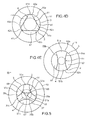
- FIGS. 4A to 4E are cross-sectional views schematically showing other exemplary shapes of the section of a trocar slidable within a catheter 10.
- the Figure 4A represents an exemplary shape of the section of a trocar 31 having three branches 31a, 31b, 31c.
- a portion 32a, 32b, 32c of the peripheral wall 2 of the trocar 31 is supported on the inner wall 3 of the catheter 10.
- the peripheral wall 2 of the trocar 31 comprises three concave portions 35a, 35b , 35c regularly distributed along the peripheral wall 2.
- the concave portions 35a, 35b, 35c respectively connect the portions 32a and 32b, 32b and 32c, 32c and 32a of the peripheral wall 2. This allows to free a space 37 between the inner wall 3 of the catheter 10 and the peripheral wall 2 of the trocar 31 at the location of each of the concave portions 35a, 35b, 35c.
- the Figures 4B and 4C represent two other examples of shape of the section of a trocar 31 comprising three branches 31a, 31b, 31c and three concave portions 35a, 35b, 35c regularly distributed along the peripheral wall 2.
- the diameter d of the circle 4 of larger diameter contained in the section of the trocar 31 is greater than the diameter d in the case of the example illustrated in FIG. Figure 4A .
- the diameter d of the circle 4 of larger diameter contained in the section of the trocar 31 is smaller than the diameter d in the case of the example illustrated in FIG. Figure 4A .
- the figure 4D represents another example of shape of the section of a trocar 41 comprising three branches 41a, 41b, 41c.
- a portion 42a, 42b, 42c of the peripheral wall 2 of the trocar 41 is supported on the inner wall 3 of the catheter 10.
- the peripheral wall 2 of the trocar 41 comprises three flats 45a, 45b, 45c regularly distributed along the peripheral wall 2.
- the flats 45a, 45b, 45c respectively connect the portions 42a and 42b, 42b and 42c, 42c and 42a of the peripheral wall 2. This frees a space 47 between the inner wall 3 of the catheter 10 and the peripheral wall 2 of the trocar 41, at the location of each of the flats 45a, 45b, 45c.
- trocar shapes for example having a different number of branches, are possible.
- the figure 4E represents an exemplary shape of the section of a trocar 51 having two branches 51a and 51b.
- a portion 52a, 52b of the peripheral wall 2 of the trocar 51 is supported on the inner wall 3 of the catheter 10.
- the peripheral wall 2 of the trocar 51 has two concave portions 55a and 55b connecting the parts 52a and 52b. This frees a space 57 between the inner wall 3 of the catheter 10 and the peripheral wall 2 of the trocar 51, at the location of each concave portion 55a, 55b.
- the circle of larger diameter contained in the section of the trocar has a diameter d less than the internal diameter D of the catheter , the smallest diameter of the circle containing the section of the trocar being less than or substantially equal to D.
- a diameter d of the order of D / 2 will be chosen so that the rigidity of the trocar is sufficient to stiffen the catheter during its introduction.
- the section of the trocar may not be uniform.
- the section of the trocar may be in the form of a helix of non-uniform section.
- the figure 5 is a sectional view schematically showing a variant of a trocar 31 able to slide inside a catheter 10.
- This variant is described in the case of a trocar 31 comprising three branches 31a, 31b, 31c and three concave portions 35a, 35b, 35c regularly distributed along the peripheral wall 2.
- this variant can be applied to a trocar comprising any number of branches greater than or equal to two.
- a central channel 63 extending along the longitudinal axis z, is arranged in the central part of the trocar 31.
- Lateral supply channels 65, 67, 69 extending along the longitudinal axis z , are arranged in the part of the trocar 31 contained in the circle 4 of diameter d.
- Each lateral supply channel 65, 67, 69 opens onto the central channel 63 and a portion of the peripheral wall 2 located respectively at the location of the concave portion 35a, 35b, 35c.
- the central channel 63 and the lateral supply channels 65, 67, 69 are intended to be traversed by the fluid to be injected.
- the free space 37 between the trocar 31 and the catheter 10 comprises three portions 37a, 37b, 37c separated by the branches 31a, 31b, 31c of the trocar 31.
- Each portion 37a, 37b, 37c is disposed between the inner wall 3 of the catheter 10 and the corresponding concave part 35a, 35b, 35c of the peripheral wall 2 of the trocar 31.
- the central channel 63 and the lateral supply channels 65, 67 , 69 the fluid to be injected can be introduced through the central channel 63 and pass into the lateral supply channels 65, 67, 69, which makes it possible to fill the three portions 37a, 37b, 37c of the free space 37 between the trocar 31 and the catheter 10.
- An advantage of such a variant lies in a simpler pre-filling by the fluid to be injected of the free space 37 between the inner wall 3 of the catheter 10 and the peripheral wall 2 of the trocar 31.
- the trocars and medical devices associating the trocars with the catheters previously described are advantageously intended to be implanted in a pathological cerebral parenchyma (neuro-degenerative or tumoral) for the localized delivery of a therapeutic principle, for example an anti-therapeutic liquid. tumor.
- a pathological cerebral parenchyma neuro-degenerative or tumoral
- a therapeutic principle for example an anti-therapeutic liquid. tumor.
Landscapes
- Health & Medical Sciences (AREA)
- Life Sciences & Earth Sciences (AREA)
- Animal Behavior & Ethology (AREA)
- General Health & Medical Sciences (AREA)
- Veterinary Medicine (AREA)
- Engineering & Computer Science (AREA)
- Biomedical Technology (AREA)
- Heart & Thoracic Surgery (AREA)
- Public Health (AREA)
- Surgery (AREA)
- Pathology (AREA)
- Molecular Biology (AREA)
- Medical Informatics (AREA)
- Nuclear Medicine, Radiotherapy & Molecular Imaging (AREA)
- Biophysics (AREA)
- Pulmonology (AREA)
- Anesthesiology (AREA)
- Hematology (AREA)
- Gastroenterology & Hepatology (AREA)
- Media Introduction/Drainage Providing Device (AREA)
Abstract
Description
- La présente invention concerne un trocart apte à coulisser à l'intérieur d'un cathéter destiné à être implanté dans une partie du corps humain, notamment pour l'injection localisée d'un fluide thérapeutique. La présente invention concerne plus particulièrement un trocart apte à coulisser à l'intérieur d'un cathéter destiné à être implanté dans un organe de structure peu compacte du corps humain, tel que le parenchyme cérébral.
- Les cathéters présentant une certaine flexibilité, ils ont tendance à dévier de leur trajectoire pendant leur insertion.
- La mise en place d'un trocart, généralement en métal, dans un cathéter permet de rendre le cathéter plus rigide pendant son implantation et donc de faciliter son guidage. Une fois le cathéter implanté, le trocart peut être retiré.
- De tels trocarts de rigidification sont couramment utilisés pour l'implantation de cathéters dans le réseau vasculaire.
- Par ailleurs, le brevet
US 8,128,600 B2 décrit un système de guidage d'un cathéter muni d'un trocart pour l'injection localisée d'un agent thérapeutique dans le parenchyme cérébral. Un trocart de faible diamètre, de l'ordre de 0,6 mm, en tungstène est introduit dans le cathéter afin d'augmenter la rigidité du cathéter pendant son implantation. Une fois le cathéter implanté, le trocart peut être extrait pour laisser place au passage de l'agent thérapeutique. - Un inconvénient des systèmes de cathéter muni d'un trocart existants réside dans la formation d'une dépression dans le cathéter lors du retrait du trocart. Ceci est dû au fait que le diamètre du trocart est proche du diamètre interne du cathéter, ce qui rend difficile le pré-remplissage de l'espace interne du cathéter par le fluide à injecter. Il en résulte un risque de formation d'une bulle d'air à l'extrémité du cathéter faisant face à la zone à traiter.
- Il se pose donc le problème de prévoir un trocart apte à coulisser à l'intérieur d'un cathéter et permettant un pré-remplissage du volume interne du cathéter par le fluide à injecter avant le retrait du trocart.
- La présente invention vise notamment à résoudre ce problème.
- La paroi interne d'un cathéter étant généralement de forme cylindrique et de section circulaire, le pré-remplissage du volume interne du cathéter par le fluide à injecter est difficile dans le cas où le trocart est également de forme cylindrique et de section circulaire et de diamètre légèrement inférieur au diamètre interne du cathéter.
- La présente invention vise donc à prévoir un trocart de forme particulière permettant un pré-remplissage du volume interne du cathéter par le fluide à injecter avant le retrait du trocart.
- La présente invention concerne un trocart comportant une paroi périphérique s'étendant selon un axe longitudinal, dont la section, dans un plan perpendiculaire audit axe longitudinal, est inscrite dans un premier cercle d'un premier diamètre, de sorte que le trocart est apte à coulisser à l'intérieur d'un cathéter comportant une paroi interne présentant des dimensions, par exemple un deuxième diamètre, supérieur(es) ou sensiblement égal(es) audit premier diamètre, le périmètre de ladite section présentant au moins une inflexion, de sorte que, lorsque le trocart coulisse dans le cathéter, au moins un espace entre le cathéter et le trocart à l'emplacement de cette inflexion reste libre.
- Par présenter une inflexion, on entend que le rayon de courbure du périmètre de ladite section n'est pas constant, ce qui permet de libérer un espace entre la paroi interne du cathéter et la paroi périphérique du trocart à l'emplacement de cette inflexion.
- Un avantage d'un trocart du type de celui décrit ci-dessus, destiné à être inséré dans un cathéter, est lié au fait qu'un espace reste libre dans le volume interne du cathéter lorsque le trocart est mis en place dans le cathéter. Cet espace libre peut contenir le fluide à injecter. Un tel trocart permet donc un pré-remplissage du volume interne du cathéter par le fluide à injecter avant le retrait du trocart. Ceci permet d'éviter la mise en dépression du cathéter lors du retrait du trocart. Il en résulte une élimination du risque de formation d'une bulle d'air à l'extrémité du cathéter, à l'emplacement de la zone à traiter par l'agent thérapeutique.
- La présente invention concerne également un trocart comportant une paroi périphérique s'étendant selon un axe longitudinal, dont la section, dans un plan perpendiculaire audit axe longitudinal, est inscrite dans un premier cercle d'un premier diamètre, de sorte que le trocart est apte à coulisser à l'intérieur d'un cathéter comportant une paroi interne présentant un deuxième diamètre supérieur ou sensiblement égal audit premier diamètre, un troisième diamètre d'un second cercle inscrit dans ladite section étant strictement inférieur au deuxième diamètre.
- Une partie de la paroi périphérique du trocart peut s'appuyer sur la paroi interne du cathéter.
- Ladite inflexion peut être formée d'un méplat. Selon une variante, ladite inflexion peut être formée d'une partie concave.
- Le troisième diamètre peut être sensiblement égal à la moitié du deuxième diamètre.
- Selon un mode de réalisation de la présente invention, le périmètre de ladite section présente au moins deux inflexions, le trocart comportant en outre un canal central, disposé dans une partie centrale du trocart et s'étendant selon l'axe longitudinal, et au moins deux canaux d'alimentation latéraux s'étendant selon l'axe longitudinal et disposés dans une partie du trocart dont la section est inscrite dans le second cercle, chaque canal d'alimentation latéral débouchant sur le canal central et sur une partie de la paroi périphérique se trouvant à l'emplacement de ladite inflexion correspondante.
- Un avantage d'un trocart du type de celui décrit ci-dessus, destiné à être inséré dans un cathéter, réside dans un pré-remplissage plus simple par le fluide à injecter de l'espace libre entre la paroi interne du cathéter et la paroi périphérique du trocart.
- Selon un mode de réalisation de la présente invention, le périmètre de ladite section présente trois inflexions régulièrement réparties le long dudit périmètre.
- La présente invention concerne en outre un dispositif médical comprenant un trocart du type de celui décrit ci-dessus et un cathéter dans lequel le trocart est apte à coulisser.
- D'autres caractéristiques et avantages de l'invention ressortiront plus clairement à la lecture de la description suivante et en référence aux dessins annexés, donnés à titre uniquement illustratif et nullement limitatif.
- La
figure 1 est une vue en coupe représentant de façon schématique un exemple de trocart selon l'invention. - La
figure 2 est une vue en coupe représentant de façon schématique un exemple de forme de la section d'un trocart selon l'invention. - La
figure 3 est une vue en coupe représentant de façon schématique un autre exemple de forme de la section d'un trocart selon l'invention. - Les
figures 4A à 4E sont des vues en coupe représentant de façon schématique d'autres exemples de forme de la section d'un trocart selon l'invention. - La
figure 5 est une vue en coupe représentant de façon schématique une variante d'un trocart selon l'invention. - Des parties identiques, similaires ou équivalentes des différentes figures portent les mêmes références numériques de façon à faciliter le passage d'une figure à l'autre.
- Les différentes parties représentées sur les figures ne le sont pas nécessairement selon une échelle uniforme, pour rendre les figures plus lisibles.
- La
figure 1 est une vue en coupe représentant de façon schématique un exemple de trocart apte à coulisser à l'intérieur d'un cathéter. - Le trocart 1 comporte une paroi périphérique 2, par exemple de forme cylindrique, s'étendant selon un axe longitudinal z. La
figure 1 représente la section du trocart 1 dans un plan perpendiculaire à l'axe longitudinal z. - Selon l'exemple illustré en
figure 1 , la section du trocart 1 est de forme irrégulière. - Le trocart 1 est apte à coulisser à l'intérieur d'un cathéter comportant une paroi interne présentant un diamètre interne D. La section du trocart 1 est inscrite dans un cercle dont le diamètre est inférieur ou sensiblement égal au diamètre interne D de la paroi interne du cathéter. Le diamètre du cercle dans lequel la section du trocart 1 est inscrite correspond au plus petit diamètre du cercle contenant la section du trocart 1.
- Le cathéter est par exemple de forme cylindrique et de section circulaire. La paroi interne du cathéter est représentée par des pointillés 3.
- Le cercle représenté par des pointillés 4, de diamètre d, correspond au cercle de plus grand diamètre contenu dans la section du trocart 1, c'est-à-dire le cercle inscrit dans la section du trocart 1.
- La forme de la section du trocart 1 sera choisie de sorte que le diamètre d soit inférieur au diamètre interne D du cathéter, et par exemple sensiblement égal à D/2.
- Une partie seulement de la paroi périphérique 2 du trocart 1 s'appuie sur la paroi interne 3 du cathéter. Le rayon de courbure du périmètre de la section du trocart 1 n'est pas constant. Le périmètre de la section du trocart 1 présente au moins une inflexion 5.
- Dans l'exemple illustré en
figure 1 , le périmètre de la section du trocart 1 présente trois inflexions 5. - La distance entre la paroi périphérique 2 du trocart 1 et la paroi interne 3 du cathéter augmente aux emplacements des inflexions 5. Ceci permet, aux emplacements des inflexions 5, de libérer un espace 7 entre la paroi interne 3 du cathéter et la paroi périphérique 2 du trocart 1.
- De préférence, chaque inflexion 5 de la paroi périphérique 2 du trocart 1 est formée d'une partie concave ou d'un méplat.
- Lorsque le trocart 1 coulisse dans le cathéter, l'espace 7 entre le cathéter et le trocart 1 aux emplacements des inflexions 5 reste libre, tandis qu'une partie de la paroi périphérique 2 du trocart 1 s'appuie sur ladite paroi interne 3 du cathéter.
- Un avantage d'un trocart du type de celui décrit en relation avec la
figure 1 , destiné à être inséré dans un cathéter, est lié au fait qu'un espace reste libre dans le volume interne du cathéter lorsque le trocart est mis en place dans le cathéter. Cet espace libre peut contenir le fluide à injecter. Un tel trocart permet donc un pré-remplissage du volume interne du cathéter par le fluide à injecter avant le retrait du trocart. Ceci permet d'éviter la mise en dépression du cathéter lors du retrait du trocart. Il en résulte une réduction du risque de formation d'une bulle d'air à l'extrémité du cathéter, à l'emplacement de la zone à traiter par l'agent thérapeutique. - Une solution pour réaliser un trocart tel que celui décrit en relation avec la
figure 1 est de partir d'un trocart présentant une section circulaire de diamètre sensiblement égal au diamètre D du cathéter, et de réaliser un ou plusieurs méplats. - La
figure 2 est une vue en coupe représentant de façon schématique un exemple de forme de la section d'un trocart 11 apte à coulisser à l'intérieur d'un cathéter 10. Selon cet exemple, le trocart 11 comprend un méplat 15. Ceci permet de libérer un espace 17 entre la paroi interne 3 du cathéter 10 et la paroi périphérique 2 du trocart 11. - La
figure 3 est une vue en coupe représentant de façon schématique un autre exemple de forme de la section d'un trocart 21 apte à coulisser à l'intérieur d'un cathéter 10. Selon cet exemple, le trocart 21 comprend trois méplats 25a, 25b, 25c. Ceci permet de libérer un espace 27 entre la paroi interne 3 du cathéter 10 et la paroi périphérique 2 du trocart 21, à l'emplacement de chacun des méplats 25a, 25b, 25c. - D'autres formes de trocart, comportant par exemple un plus grand nombre de méplats, sont possibles.
- Les
figures 4A à 4E sont des vues en coupe représentant de façon schématique d'autres exemples de forme de la section d'un trocart apte à coulisser à l'intérieur d'un cathéter 10. - La
figure 4A représente un exemple de forme de la section d'un trocart 31 comportant trois branches 31a, 31b, 31c. Dans chaque branche 31a, 31b, 31c, une partie 32a, 32b, 32c de la paroi périphérique 2 du trocart 31 s'appuie sur la paroi interne 3 du cathéter 10. La paroi périphérique 2 du trocart 31 comprend trois parties concaves 35a, 35b, 35c régulièrement réparties le long de la paroi périphérique 2. Les parties concaves 35a, 35b, 35c relient respectivement les parties 32a et 32b, 32b et 32c, 32c et 32a de la paroi périphérique 2. Ceci permet de libérer un espace 37 entre la paroi interne 3 du cathéter 10 et la paroi périphérique 2 du trocart 31, à l'emplacement de chacune des parties concaves 35a, 35b, 35c. - Les
figures 4B et 4C représentent deux autres exemples de forme de la section d'un trocart 31 comprenant trois branches 31a, 31b, 31c et trois parties concaves 35a, 35b, 35c régulièrement réparties le long de la paroi périphérique 2. Selon l'exemple illustré enfigure 4B , le diamètre d du cercle 4 de plus grand diamètre contenu dans la section du trocart 31 est supérieur au diamètre d dans le cas de l'exemple illustré enfigure 4A . Selon l'exemple illustré enfigure 4C , le diamètre d du cercle 4 de plus grand diamètre contenu dans la section du trocart 31 est inférieur au diamètre d dans le cas de l'exemple illustré enfigure 4A . - La
figure 4D représente un autre exemple de forme de la section d'un trocart 41 comprenant trois branches 41a, 41b, 41c. Dans chaque branche 41a, 41b, 41c, une partie 42a, 42b, 42c de la paroi périphérique 2 du trocart 41 s'appuie sur la paroi interne 3 du cathéter 10. La paroi périphérique 2 du trocart 41 comprend trois méplats 45a, 45b, 45c régulièrement répartis le long de la paroi périphérique 2. Les méplats 45a, 45b, 45c relient respectivement les parties 42a et 42b, 42b et 42c, 42c et 42a de la paroi périphérique 2. Ceci permet de libérer un espace 47 entre la paroi interne 3 du cathéter 10 et la paroi périphérique 2 du trocart 41, à l'emplacement de chacun des méplats 45a, 45b, 45c. - D'autres formes de trocart, comportant par exemple un nombre différent de branches, sont possibles.
- La
figure 4E représente un exemple de forme de la section d'un trocart 51 comportant deux branches 51a et 51b. Dans chaque branche 51a, 51b, une partie 52a, 52b de la paroi périphérique 2 du trocart 51 s'appuie sur la paroi interne 3 du cathéter 10. La paroi périphérique 2 du trocart 51 comporte deux parties concaves 55a et 55b reliant les parties 52a et 52b. Ceci permet de libérer un espace 57 entre la paroi interne 3 du cathéter 10 et la paroi périphérique 2 du trocart 51, à l'emplacement de chaque partie concave 55a, 55b. - D'une manière générale, il suffit de respecter la règle édictée pour la section du trocart, c'est-à-dire que le cercle de plus grand diamètre contenu dans la section du trocart présente un diamètre d inférieur au diamètre interne D du cathéter, le plus petit diamètre du cercle contenant la section du trocart étant inférieur ou sensiblement égal à D.
- On choisira par exemple un diamètre d de l'ordre de D/2 de façon que la rigidité du trocart soit suffisante pour rigidifier le cathéter lors de son introduction.
- En outre, la section du trocart peut ne pas être uniforme. Par exemple, la section du trocart peut présenter la forme d'une hélice de section non uniforme.
- La
figure 5 est une vue en coupe représentant de façon schématique une variante d'un trocart 31 apte à coulisser à l'intérieur d'un cathéter 10. Cette variante est décrite dans le cas d'un trocart 31 comprenant trois branches 31a, 31b, 31c et trois parties concaves 35a, 35b, 35c régulièrement réparties le long de la paroi périphérique 2. Bien entendu, cette variante peut s'appliquer à un trocart comprenant un nombre quelconque de branches supérieur ou égal à deux. - Selon cette variante, un canal central 63, s'étendant selon l'axe longitudinal z, est disposé dans la partie centrale du trocart 31. Des canaux d'alimentation latéraux 65, 67, 69, s'étendant selon l'axe longitudinal z, sont disposés dans la partie du trocart 31 contenue dans le cercle 4 de diamètre d. Chaque canal d'alimentation latéral 65, 67, 69 débouche sur le canal central 63 et sur une partie de la paroi périphérique 2 se trouvant respectivement à l'emplacement de la partie concave 35a, 35b, 35c. Le canal central 63 et les canaux d'alimentation latéraux 65, 67, 69 sont destinés à être traversés par le fluide à injecter.
- L'espace libre 37 entre le trocart 31 et le cathéter 10 comprend trois portions 37a, 37b, 37c séparées par les branches 31a, 31b, 31c du trocart 31. Chaque portion 37a, 37b, 37c est disposée entre la paroi interne 3 du cathéter 10 et la partie concave 35a, 35b, 35c correspondante de la paroi périphérique 2 du trocart 31. Grâce au canal central 63 et aux canaux d'alimentation latéraux 65, 67, 69, le fluide à injecter peut être introduit par le canal central 63 et passer dans les canaux d'alimentation latéraux 65, 67, 69, ce qui permet de remplir les trois portions 37a, 37b, 37c de l'espace libre 37 entre le trocart 31 et le cathéter 10.
- Un avantage d'une telle variante réside dans un pré-remplissage plus simple par le fluide à injecter de l'espace libre 37 entre la paroi interne 3 du cathéter 10 et la paroi périphérique 2 du trocart 31.
- Bien que la variante de la
figure 5 ait été décrite dans le cas où les inflexions de la paroi périphérique du trocart sont formées de parties concaves, cette variante s'applique bien entendu au cas où ces inflexions sont formées de méplats. - Les trocarts et les dispositifs médicaux associant les trocarts aux cathéters précédemment décrits sont avantageusement destinés à être implantés dans un parenchyme cérébral pathologique (neuro-dégénératif ou tumoral) pour la délivrance localisée d'un principe thérapeutique, par exemple d'un liquide thérapeutique anti-tumoral.
Claims (6)
- Trocart (1, 11, 21, 31, 41, 51) comportant une paroi périphérique (2) s'étendant selon un axe longitudinal (z), dont la section, dans un plan perpendiculaire audit axe longitudinal, est inscrite dans un premier cercle d'un premier diamètre, de sorte que le trocart est apte à coulisser à l'intérieur d'un cathéter (10) comportant une paroi interne (3) présentant des dimensions (D) supérieures ou sensiblement égales audit premier diamètre,
le périmètre de ladite section présentant au moins une inflexion (5), de sorte que, lorsque le trocart coulisse dans le cathéter (10), au moins un espace (7, 17, 27, 37, 47, 57) entre le cathéter et le trocart à l'emplacement de cette inflexion reste libre,
dans lequel un troisième diamètre (d) d'un second cercle (4) inscrit dans ladite section est strictement inférieur aux dimensions (D) de la paroi interne (3) du cathéter (10),
et dans lequel le périmètre de ladite section présente au moins deux inflexions (35a, 35b, 35c), le trocart comportant en outre :un canal central (63) disposé dans une partie centrale du trocart (31) et s'étendant selon l'axe longitudinal (z) ; etau moins deux canaux d'alimentation latéraux (65, 67, 69) s'étendant selon l'axe longitudinal (z) et disposés dans une partie du trocart dont la section est inscrite dans le second cercle (4),et dans lequel chaque canal d'alimentation latéral débouche sur le canal central et sur une partie de la paroi périphérique (2) se trouvant à l'emplacement de ladite inflexion correspondante (35a, 35b, 35c). - Trocart selon la revendication 1, dans lequel ladite inflexion (5) est formée d'un méplat (15; 25a, 25b, 25c) ou d'une partie concave (35a, 35b, 35c; 55a, 55b).
- Trocart selon la revendication 1 ou 2, dans lequel le troisième diamètre (d) est sensiblement égal à la moitié des dimensions (D) de la paroi interne (3) du cathéter (10).
- Trocart selon l'une des revendications 1 à 3, dans lequel le périmètre de ladite section présente trois inflexions (35a, 35b, 35c) régulièrement réparties le long dudit périmètre.
- Trocart selon l'une des revendications 1 à 4, dans lequel la paroi interne (3) du cathéter (10) est de section circulaire, les dimensions (D) de la paroi interne (3) correspondant à un deuxième diamètre.
- Dispositif médical comprenant un trocart (1, 11, 21, 31, 41, 51) selon l'une des revendications 1 à 5 et un cathéter (10) dans lequel le trocart est apte à coulisser.
Applications Claiming Priority (1)
| Application Number | Priority Date | Filing Date | Title |
|---|---|---|---|
| FR1459609A FR3026633A1 (fr) | 2014-10-07 | 2014-10-07 | Trocart de rigidification d'un catheter |
Publications (2)
| Publication Number | Publication Date |
|---|---|
| EP3006073A1 true EP3006073A1 (fr) | 2016-04-13 |
| EP3006073B1 EP3006073B1 (fr) | 2019-12-18 |
Family
ID=52345295
Family Applications (1)
| Application Number | Title | Priority Date | Filing Date |
|---|---|---|---|
| EP15188696.7A Active EP3006073B1 (fr) | 2014-10-07 | 2015-10-07 | Trocart de rigidification d'un catheter |
Country Status (2)
| Country | Link |
|---|---|
| EP (1) | EP3006073B1 (fr) |
| FR (1) | FR3026633A1 (fr) |
Citations (5)
| Publication number | Priority date | Publication date | Assignee | Title |
|---|---|---|---|---|
| EP1597999A1 (fr) * | 2004-05-17 | 2005-11-23 | Richard Wolf GmbH | Dispositif endoscopique |
| WO2008042285A2 (fr) * | 2006-09-29 | 2008-04-10 | Tyco Healthcare Group Lp | Dispositif de transfert de fluide chirurgical |
| WO2010089727A1 (fr) * | 2009-02-09 | 2010-08-12 | Yuval Jacoby | Canule intraveineuse |
| US8128600B2 (en) | 2002-03-12 | 2012-03-06 | Renishaw (Ireland) Limited | Catheter and guide tube for intracerebral application |
| US20130096482A1 (en) * | 2011-10-18 | 2013-04-18 | Medtronic Xomed, Inc. | Alternate geometry stylet for ventricular shunt catheter placement |
-
2014
- 2014-10-07 FR FR1459609A patent/FR3026633A1/fr not_active Ceased
-
2015
- 2015-10-07 EP EP15188696.7A patent/EP3006073B1/fr active Active
Patent Citations (5)
| Publication number | Priority date | Publication date | Assignee | Title |
|---|---|---|---|---|
| US8128600B2 (en) | 2002-03-12 | 2012-03-06 | Renishaw (Ireland) Limited | Catheter and guide tube for intracerebral application |
| EP1597999A1 (fr) * | 2004-05-17 | 2005-11-23 | Richard Wolf GmbH | Dispositif endoscopique |
| WO2008042285A2 (fr) * | 2006-09-29 | 2008-04-10 | Tyco Healthcare Group Lp | Dispositif de transfert de fluide chirurgical |
| WO2010089727A1 (fr) * | 2009-02-09 | 2010-08-12 | Yuval Jacoby | Canule intraveineuse |
| US20130096482A1 (en) * | 2011-10-18 | 2013-04-18 | Medtronic Xomed, Inc. | Alternate geometry stylet for ventricular shunt catheter placement |
Also Published As
| Publication number | Publication date |
|---|---|
| EP3006073B1 (fr) | 2019-12-18 |
| FR3026633A1 (fr) | 2016-04-08 |
Similar Documents
| Publication | Publication Date | Title |
|---|---|---|
| EP1259283B1 (fr) | Dispositif implantable d'injection de substances medicales | |
| WO1990000073A1 (fr) | Seringue du type comportant une aiguille d'injection a usage unique, notamment pour le domaine dentaire | |
| FR2848858A1 (fr) | Embout de dechargement de serringue concu pour assurer un debit regulier | |
| FR3011186A1 (fr) | Dispositif de reception pour une seringue d'injection comprenant un capuchon de protection de l'aiguille | |
| FR3061647A1 (fr) | Dispositif intra-anevrismal | |
| FR2959927A1 (fr) | Systeme de retention d'un organe d'ancrage sur une piece implantable | |
| EP0367677A1 (fr) | Dispositif d'injection sous cutanée sans aiguille | |
| WO1989000432A2 (fr) | Seringue de haute securite non reutilisable | |
| FR3043562A1 (fr) | Autoinjecteur. | |
| FR3042108A1 (fr) | Systeme de voie d'abord pour operations endoscopiques | |
| EP3319667A1 (fr) | Seringue et son procédé d'assemblage | |
| EP3006073B1 (fr) | Trocart de rigidification d'un catheter | |
| CH707745A1 (fr) | Instrument endodontique, notamment pour l'alésage d'un canal radiculaire. | |
| FR3043563A1 (fr) | Autoinjecteur. | |
| EP3352821A1 (fr) | Ensemble de distribution comportant une seringue et un dispositif de protection pour aiguille | |
| CA2987214C (fr) | Boitier de montage d'un recipient sur un stylo injecteur, ensemble formant reservoir de produit injectable pour un stylo injecteur et un stylo injecteur equipe d'un tel ensemble | |
| EP3265026A1 (fr) | Endoprothèse et cathéter perfectionnés | |
| FR2613230A1 (fr) | Seringue | |
| FR3019981A1 (fr) | Materiel d'osteosynthese vertebrale | |
| FR2627698A1 (fr) | Cartouche d'injection de medicament a utiliser dans un injecteur a vide-compression | |
| EP0746364B1 (fr) | Dispositif de securite pour seringue a usage dentaire | |
| FR2607707A1 (fr) | Embase amovible pour catheter et catheter adapte a celle-ci | |
| FR3038840A1 (fr) | Dispositif de securite pour une seringue d'injection. | |
| FR2909546A1 (fr) | Pointe de micromanipulateur chirurgical,micromanipulateur chirurgical et procede de fabrication d'une pointe pour un tel micromanipulateur. | |
| WO2004004822A1 (fr) | Dispositif pour l'insertion d'implants |
Legal Events
| Date | Code | Title | Description |
|---|---|---|---|
| PUAI | Public reference made under article 153(3) epc to a published international application that has entered the european phase |
Free format text: ORIGINAL CODE: 0009012 |
|
| AK | Designated contracting states |
Kind code of ref document: A1 Designated state(s): AL AT BE BG CH CY CZ DE DK EE ES FI FR GB GR HR HU IE IS IT LI LT LU LV MC MK MT NL NO PL PT RO RS SE SI SK SM TR |
|
| AX | Request for extension of the european patent |
Extension state: BA ME |
|
| 17P | Request for examination filed |
Effective date: 20160916 |
|
| RBV | Designated contracting states (corrected) |
Designated state(s): AL AT BE BG CH CY CZ DE DK EE ES FI FR GB GR HR HU IE IS IT LI LT LU LV MC MK MT NL NO PL PT RO RS SE SI SK SM TR |
|
| GRAP | Despatch of communication of intention to grant a patent |
Free format text: ORIGINAL CODE: EPIDOSNIGR1 |
|
| STAA | Information on the status of an ep patent application or granted ep patent |
Free format text: STATUS: GRANT OF PATENT IS INTENDED |
|
| INTG | Intention to grant announced |
Effective date: 20190708 |
|
| GRAS | Grant fee paid |
Free format text: ORIGINAL CODE: EPIDOSNIGR3 |
|
| GRAA | (expected) grant |
Free format text: ORIGINAL CODE: 0009210 |
|
| STAA | Information on the status of an ep patent application or granted ep patent |
Free format text: STATUS: THE PATENT HAS BEEN GRANTED |
|
| AK | Designated contracting states |
Kind code of ref document: B1 Designated state(s): AL AT BE BG CH CY CZ DE DK EE ES FI FR GB GR HR HU IE IS IT LI LT LU LV MC MK MT NL NO PL PT RO RS SE SI SK SM TR |
|
| REG | Reference to a national code |
Ref country code: CH Ref legal event code: EP |
|
| REG | Reference to a national code |
Ref country code: IE Ref legal event code: FG4D Free format text: LANGUAGE OF EP DOCUMENT: FRENCH |
|
| REG | Reference to a national code |
Ref country code: DE Ref legal event code: R096 Ref document number: 602015043765 Country of ref document: DE |
|
| REG | Reference to a national code |
Ref country code: AT Ref legal event code: REF Ref document number: 1213902 Country of ref document: AT Kind code of ref document: T Effective date: 20200115 |
|
| REG | Reference to a national code |
Ref country code: NL Ref legal event code: MP Effective date: 20191218 |
|
| PG25 | Lapsed in a contracting state [announced via postgrant information from national office to epo] |
Ref country code: LV Free format text: LAPSE BECAUSE OF FAILURE TO SUBMIT A TRANSLATION OF THE DESCRIPTION OR TO PAY THE FEE WITHIN THE PRESCRIBED TIME-LIMIT Effective date: 20191218 Ref country code: SE Free format text: LAPSE BECAUSE OF FAILURE TO SUBMIT A TRANSLATION OF THE DESCRIPTION OR TO PAY THE FEE WITHIN THE PRESCRIBED TIME-LIMIT Effective date: 20191218 Ref country code: BG Free format text: LAPSE BECAUSE OF FAILURE TO SUBMIT A TRANSLATION OF THE DESCRIPTION OR TO PAY THE FEE WITHIN THE PRESCRIBED TIME-LIMIT Effective date: 20200318 Ref country code: FI Free format text: LAPSE BECAUSE OF FAILURE TO SUBMIT A TRANSLATION OF THE DESCRIPTION OR TO PAY THE FEE WITHIN THE PRESCRIBED TIME-LIMIT Effective date: 20191218 Ref country code: LT Free format text: LAPSE BECAUSE OF FAILURE TO SUBMIT A TRANSLATION OF THE DESCRIPTION OR TO PAY THE FEE WITHIN THE PRESCRIBED TIME-LIMIT Effective date: 20191218 Ref country code: NO Free format text: LAPSE BECAUSE OF FAILURE TO SUBMIT A TRANSLATION OF THE DESCRIPTION OR TO PAY THE FEE WITHIN THE PRESCRIBED TIME-LIMIT Effective date: 20200318 Ref country code: GR Free format text: LAPSE BECAUSE OF FAILURE TO SUBMIT A TRANSLATION OF THE DESCRIPTION OR TO PAY THE FEE WITHIN THE PRESCRIBED TIME-LIMIT Effective date: 20200319 |
|
| REG | Reference to a national code |
Ref country code: LT Ref legal event code: MG4D |
|
| PG25 | Lapsed in a contracting state [announced via postgrant information from national office to epo] |
Ref country code: HR Free format text: LAPSE BECAUSE OF FAILURE TO SUBMIT A TRANSLATION OF THE DESCRIPTION OR TO PAY THE FEE WITHIN THE PRESCRIBED TIME-LIMIT Effective date: 20191218 Ref country code: RS Free format text: LAPSE BECAUSE OF FAILURE TO SUBMIT A TRANSLATION OF THE DESCRIPTION OR TO PAY THE FEE WITHIN THE PRESCRIBED TIME-LIMIT Effective date: 20191218 |
|
| PG25 | Lapsed in a contracting state [announced via postgrant information from national office to epo] |
Ref country code: AL Free format text: LAPSE BECAUSE OF FAILURE TO SUBMIT A TRANSLATION OF THE DESCRIPTION OR TO PAY THE FEE WITHIN THE PRESCRIBED TIME-LIMIT Effective date: 20191218 |
|
| PG25 | Lapsed in a contracting state [announced via postgrant information from national office to epo] |
Ref country code: PT Free format text: LAPSE BECAUSE OF FAILURE TO SUBMIT A TRANSLATION OF THE DESCRIPTION OR TO PAY THE FEE WITHIN THE PRESCRIBED TIME-LIMIT Effective date: 20200513 Ref country code: NL Free format text: LAPSE BECAUSE OF FAILURE TO SUBMIT A TRANSLATION OF THE DESCRIPTION OR TO PAY THE FEE WITHIN THE PRESCRIBED TIME-LIMIT Effective date: 20191218 Ref country code: RO Free format text: LAPSE BECAUSE OF FAILURE TO SUBMIT A TRANSLATION OF THE DESCRIPTION OR TO PAY THE FEE WITHIN THE PRESCRIBED TIME-LIMIT Effective date: 20191218 Ref country code: CZ Free format text: LAPSE BECAUSE OF FAILURE TO SUBMIT A TRANSLATION OF THE DESCRIPTION OR TO PAY THE FEE WITHIN THE PRESCRIBED TIME-LIMIT Effective date: 20191218 Ref country code: EE Free format text: LAPSE BECAUSE OF FAILURE TO SUBMIT A TRANSLATION OF THE DESCRIPTION OR TO PAY THE FEE WITHIN THE PRESCRIBED TIME-LIMIT Effective date: 20191218 |
|
| PG25 | Lapsed in a contracting state [announced via postgrant information from national office to epo] |
Ref country code: IS Free format text: LAPSE BECAUSE OF FAILURE TO SUBMIT A TRANSLATION OF THE DESCRIPTION OR TO PAY THE FEE WITHIN THE PRESCRIBED TIME-LIMIT Effective date: 20200418 Ref country code: SK Free format text: LAPSE BECAUSE OF FAILURE TO SUBMIT A TRANSLATION OF THE DESCRIPTION OR TO PAY THE FEE WITHIN THE PRESCRIBED TIME-LIMIT Effective date: 20191218 Ref country code: SM Free format text: LAPSE BECAUSE OF FAILURE TO SUBMIT A TRANSLATION OF THE DESCRIPTION OR TO PAY THE FEE WITHIN THE PRESCRIBED TIME-LIMIT Effective date: 20191218 |
|
| REG | Reference to a national code |
Ref country code: DE Ref legal event code: R097 Ref document number: 602015043765 Country of ref document: DE |
|
| REG | Reference to a national code |
Ref country code: AT Ref legal event code: MK05 Ref document number: 1213902 Country of ref document: AT Kind code of ref document: T Effective date: 20191218 |
|
| PLBE | No opposition filed within time limit |
Free format text: ORIGINAL CODE: 0009261 |
|
| STAA | Information on the status of an ep patent application or granted ep patent |
Free format text: STATUS: NO OPPOSITION FILED WITHIN TIME LIMIT |
|
| PG25 | Lapsed in a contracting state [announced via postgrant information from national office to epo] |
Ref country code: DK Free format text: LAPSE BECAUSE OF FAILURE TO SUBMIT A TRANSLATION OF THE DESCRIPTION OR TO PAY THE FEE WITHIN THE PRESCRIBED TIME-LIMIT Effective date: 20191218 Ref country code: ES Free format text: LAPSE BECAUSE OF FAILURE TO SUBMIT A TRANSLATION OF THE DESCRIPTION OR TO PAY THE FEE WITHIN THE PRESCRIBED TIME-LIMIT Effective date: 20191218 |
|
| 26N | No opposition filed |
Effective date: 20200921 |
|
| PG25 | Lapsed in a contracting state [announced via postgrant information from national office to epo] |
Ref country code: AT Free format text: LAPSE BECAUSE OF FAILURE TO SUBMIT A TRANSLATION OF THE DESCRIPTION OR TO PAY THE FEE WITHIN THE PRESCRIBED TIME-LIMIT Effective date: 20191218 Ref country code: SI Free format text: LAPSE BECAUSE OF FAILURE TO SUBMIT A TRANSLATION OF THE DESCRIPTION OR TO PAY THE FEE WITHIN THE PRESCRIBED TIME-LIMIT Effective date: 20191218 |
|
| PG25 | Lapsed in a contracting state [announced via postgrant information from national office to epo] |
Ref country code: IT Free format text: LAPSE BECAUSE OF FAILURE TO SUBMIT A TRANSLATION OF THE DESCRIPTION OR TO PAY THE FEE WITHIN THE PRESCRIBED TIME-LIMIT Effective date: 20191218 |
|
| PG25 | Lapsed in a contracting state [announced via postgrant information from national office to epo] |
Ref country code: PL Free format text: LAPSE BECAUSE OF FAILURE TO SUBMIT A TRANSLATION OF THE DESCRIPTION OR TO PAY THE FEE WITHIN THE PRESCRIBED TIME-LIMIT Effective date: 20191218 |
|
| REG | Reference to a national code |
Ref country code: CH Ref legal event code: PL |
|
| PG25 | Lapsed in a contracting state [announced via postgrant information from national office to epo] |
Ref country code: MC Free format text: LAPSE BECAUSE OF FAILURE TO SUBMIT A TRANSLATION OF THE DESCRIPTION OR TO PAY THE FEE WITHIN THE PRESCRIBED TIME-LIMIT Effective date: 20191218 Ref country code: LU Free format text: LAPSE BECAUSE OF NON-PAYMENT OF DUE FEES Effective date: 20201007 |
|
| REG | Reference to a national code |
Ref country code: BE Ref legal event code: MM Effective date: 20201031 |
|
| PG25 | Lapsed in a contracting state [announced via postgrant information from national office to epo] |
Ref country code: CH Free format text: LAPSE BECAUSE OF NON-PAYMENT OF DUE FEES Effective date: 20201031 Ref country code: BE Free format text: LAPSE BECAUSE OF NON-PAYMENT OF DUE FEES Effective date: 20201031 Ref country code: LI Free format text: LAPSE BECAUSE OF NON-PAYMENT OF DUE FEES Effective date: 20201031 |
|
| PG25 | Lapsed in a contracting state [announced via postgrant information from national office to epo] |
Ref country code: IE Free format text: LAPSE BECAUSE OF NON-PAYMENT OF DUE FEES Effective date: 20201007 |
|
| PGFP | Annual fee paid to national office [announced via postgrant information from national office to epo] |
Ref country code: GB Payment date: 20211020 Year of fee payment: 7 Ref country code: DE Payment date: 20211008 Year of fee payment: 7 |
|
| PGFP | Annual fee paid to national office [announced via postgrant information from national office to epo] |
Ref country code: FR Payment date: 20211029 Year of fee payment: 7 |
|
| PG25 | Lapsed in a contracting state [announced via postgrant information from national office to epo] |
Ref country code: TR Free format text: LAPSE BECAUSE OF FAILURE TO SUBMIT A TRANSLATION OF THE DESCRIPTION OR TO PAY THE FEE WITHIN THE PRESCRIBED TIME-LIMIT Effective date: 20191218 Ref country code: MT Free format text: LAPSE BECAUSE OF FAILURE TO SUBMIT A TRANSLATION OF THE DESCRIPTION OR TO PAY THE FEE WITHIN THE PRESCRIBED TIME-LIMIT Effective date: 20191218 Ref country code: CY Free format text: LAPSE BECAUSE OF FAILURE TO SUBMIT A TRANSLATION OF THE DESCRIPTION OR TO PAY THE FEE WITHIN THE PRESCRIBED TIME-LIMIT Effective date: 20191218 |
|
| PG25 | Lapsed in a contracting state [announced via postgrant information from national office to epo] |
Ref country code: MK Free format text: LAPSE BECAUSE OF FAILURE TO SUBMIT A TRANSLATION OF THE DESCRIPTION OR TO PAY THE FEE WITHIN THE PRESCRIBED TIME-LIMIT Effective date: 20191218 |
|
| REG | Reference to a national code |
Ref country code: DE Ref legal event code: R119 Ref document number: 602015043765 Country of ref document: DE |
|
| GBPC | Gb: european patent ceased through non-payment of renewal fee |
Effective date: 20221007 |
|
| PG25 | Lapsed in a contracting state [announced via postgrant information from national office to epo] |
Ref country code: FR Free format text: LAPSE BECAUSE OF NON-PAYMENT OF DUE FEES Effective date: 20221031 Ref country code: DE Free format text: LAPSE BECAUSE OF NON-PAYMENT OF DUE FEES Effective date: 20230503 |
|
| PG25 | Lapsed in a contracting state [announced via postgrant information from national office to epo] |
Ref country code: GB Free format text: LAPSE BECAUSE OF NON-PAYMENT OF DUE FEES Effective date: 20221007 |