EP3005998A1 - Sanitary towel - Google Patents
Sanitary towel Download PDFInfo
- Publication number
- EP3005998A1 EP3005998A1 EP14804766.5A EP14804766A EP3005998A1 EP 3005998 A1 EP3005998 A1 EP 3005998A1 EP 14804766 A EP14804766 A EP 14804766A EP 3005998 A1 EP3005998 A1 EP 3005998A1
- Authority
- EP
- European Patent Office
- Prior art keywords
- layer side
- sanitary towel
- joint area
- upper layer
- elastic member
- Prior art date
- Legal status (The legal status is an assumption and is not a legal conclusion. Google has not performed a legal analysis and makes no representation as to the accuracy of the status listed.)
- Granted
Links
Images

Classifications
-
- A—HUMAN NECESSITIES
- A61—MEDICAL OR VETERINARY SCIENCE; HYGIENE
- A61F—FILTERS IMPLANTABLE INTO BLOOD VESSELS; PROSTHESES; DEVICES PROVIDING PATENCY TO, OR PREVENTING COLLAPSING OF, TUBULAR STRUCTURES OF THE BODY, e.g. STENTS; ORTHOPAEDIC, NURSING OR CONTRACEPTIVE DEVICES; FOMENTATION; TREATMENT OR PROTECTION OF EYES OR EARS; BANDAGES, DRESSINGS OR ABSORBENT PADS; FIRST-AID KITS
- A61F13/00—Bandages or dressings; Absorbent pads
- A61F13/15—Absorbent pads, e.g. sanitary towels, swabs or tampons for external or internal application to the body; Supporting or fastening means therefor; Tampon applicators
-
- A—HUMAN NECESSITIES
- A61—MEDICAL OR VETERINARY SCIENCE; HYGIENE
- A61F—FILTERS IMPLANTABLE INTO BLOOD VESSELS; PROSTHESES; DEVICES PROVIDING PATENCY TO, OR PREVENTING COLLAPSING OF, TUBULAR STRUCTURES OF THE BODY, e.g. STENTS; ORTHOPAEDIC, NURSING OR CONTRACEPTIVE DEVICES; FOMENTATION; TREATMENT OR PROTECTION OF EYES OR EARS; BANDAGES, DRESSINGS OR ABSORBENT PADS; FIRST-AID KITS
- A61F13/00—Bandages or dressings; Absorbent pads
- A61F13/15—Absorbent pads, e.g. sanitary towels, swabs or tampons for external or internal application to the body; Supporting or fastening means therefor; Tampon applicators
- A61F13/45—Absorbent pads, e.g. sanitary towels, swabs or tampons for external or internal application to the body; Supporting or fastening means therefor; Tampon applicators characterised by the shape
- A61F13/47—Sanitary towels, incontinence pads or napkins
- A61F13/475—Sanitary towels, incontinence pads or napkins characterised by edge leakage prevention means
- A61F13/4758—Sanitary towels, incontinence pads or napkins characterised by edge leakage prevention means the means preventing fluid flow in a longitudinal direction
-
- A—HUMAN NECESSITIES
- A61—MEDICAL OR VETERINARY SCIENCE; HYGIENE
- A61F—FILTERS IMPLANTABLE INTO BLOOD VESSELS; PROSTHESES; DEVICES PROVIDING PATENCY TO, OR PREVENTING COLLAPSING OF, TUBULAR STRUCTURES OF THE BODY, e.g. STENTS; ORTHOPAEDIC, NURSING OR CONTRACEPTIVE DEVICES; FOMENTATION; TREATMENT OR PROTECTION OF EYES OR EARS; BANDAGES, DRESSINGS OR ABSORBENT PADS; FIRST-AID KITS
- A61F13/00—Bandages or dressings; Absorbent pads
- A61F13/15—Absorbent pads, e.g. sanitary towels, swabs or tampons for external or internal application to the body; Supporting or fastening means therefor; Tampon applicators
- A61F13/45—Absorbent pads, e.g. sanitary towels, swabs or tampons for external or internal application to the body; Supporting or fastening means therefor; Tampon applicators characterised by the shape
- A61F13/47—Sanitary towels, incontinence pads or napkins
- A61F13/4704—Sanitary towels, incontinence pads or napkins having preferential bending zones, e.g. fold lines or grooves
-
- A—HUMAN NECESSITIES
- A61—MEDICAL OR VETERINARY SCIENCE; HYGIENE
- A61F—FILTERS IMPLANTABLE INTO BLOOD VESSELS; PROSTHESES; DEVICES PROVIDING PATENCY TO, OR PREVENTING COLLAPSING OF, TUBULAR STRUCTURES OF THE BODY, e.g. STENTS; ORTHOPAEDIC, NURSING OR CONTRACEPTIVE DEVICES; FOMENTATION; TREATMENT OR PROTECTION OF EYES OR EARS; BANDAGES, DRESSINGS OR ABSORBENT PADS; FIRST-AID KITS
- A61F13/00—Bandages or dressings; Absorbent pads
- A61F13/15—Absorbent pads, e.g. sanitary towels, swabs or tampons for external or internal application to the body; Supporting or fastening means therefor; Tampon applicators
- A61F13/45—Absorbent pads, e.g. sanitary towels, swabs or tampons for external or internal application to the body; Supporting or fastening means therefor; Tampon applicators characterised by the shape
- A61F13/47—Sanitary towels, incontinence pads or napkins
- A61F13/475—Sanitary towels, incontinence pads or napkins characterised by edge leakage prevention means
- A61F13/4751—Sanitary towels, incontinence pads or napkins characterised by edge leakage prevention means the means preventing fluid flow in a transversal direction
- A61F13/4752—Sanitary towels, incontinence pads or napkins characterised by edge leakage prevention means the means preventing fluid flow in a transversal direction the means being an upstanding barrier
- A61F13/4753—Sanitary towels, incontinence pads or napkins characterised by edge leakage prevention means the means preventing fluid flow in a transversal direction the means being an upstanding barrier the barrier being not integral with the topsheet or backsheet
-
- A—HUMAN NECESSITIES
- A61—MEDICAL OR VETERINARY SCIENCE; HYGIENE
- A61F—FILTERS IMPLANTABLE INTO BLOOD VESSELS; PROSTHESES; DEVICES PROVIDING PATENCY TO, OR PREVENTING COLLAPSING OF, TUBULAR STRUCTURES OF THE BODY, e.g. STENTS; ORTHOPAEDIC, NURSING OR CONTRACEPTIVE DEVICES; FOMENTATION; TREATMENT OR PROTECTION OF EYES OR EARS; BANDAGES, DRESSINGS OR ABSORBENT PADS; FIRST-AID KITS
- A61F13/00—Bandages or dressings; Absorbent pads
- A61F13/15—Absorbent pads, e.g. sanitary towels, swabs or tampons for external or internal application to the body; Supporting or fastening means therefor; Tampon applicators
- A61F13/45—Absorbent pads, e.g. sanitary towels, swabs or tampons for external or internal application to the body; Supporting or fastening means therefor; Tampon applicators characterised by the shape
- A61F2013/4512—Absorbent pads, e.g. sanitary towels, swabs or tampons for external or internal application to the body; Supporting or fastening means therefor; Tampon applicators characterised by the shape folded in special shape during use
-
- A—HUMAN NECESSITIES
- A61—MEDICAL OR VETERINARY SCIENCE; HYGIENE
- A61F—FILTERS IMPLANTABLE INTO BLOOD VESSELS; PROSTHESES; DEVICES PROVIDING PATENCY TO, OR PREVENTING COLLAPSING OF, TUBULAR STRUCTURES OF THE BODY, e.g. STENTS; ORTHOPAEDIC, NURSING OR CONTRACEPTIVE DEVICES; FOMENTATION; TREATMENT OR PROTECTION OF EYES OR EARS; BANDAGES, DRESSINGS OR ABSORBENT PADS; FIRST-AID KITS
- A61F13/00—Bandages or dressings; Absorbent pads
- A61F13/15—Absorbent pads, e.g. sanitary towels, swabs or tampons for external or internal application to the body; Supporting or fastening means therefor; Tampon applicators
- A61F13/45—Absorbent pads, e.g. sanitary towels, swabs or tampons for external or internal application to the body; Supporting or fastening means therefor; Tampon applicators characterised by the shape
- A61F13/47—Sanitary towels, incontinence pads or napkins
- A61F2013/4708—Panty-liner
Definitions
- the present invention relates to a sanitary towel that mainly absorbs menstrual blood, vaginal discharge or the like, in more detail, relates to a thin sanitary towel provided with solid gathers each standing on a skin side at both sides of a front side.
- Patent Literature 1 a solid gather is disclosed in which, when a side nonwoven fabric is disposed in the intermediate portion in a height direction with a plurality of elastic expandable members, adhered to an absorber side in a state in which front and back end portions are laminated by folding in a Z shape in a cross-section, the solid gather stands-up on a front side while forming a pocket with an opening directed to an inside in an L-shaped cross section with a site where the elastic expandable members are disposed as a bending point.
- Patent Literature 1 a solid gather that stands-up simply in line by adhering to the absorber side in a state where front and back end portions of the side nonwoven fabric are folded back outward is disclosed.
- an absorbing article in which an elastic material that is disposed along a free end and exhibits an elastic contractile force and an elastic material that forms a contract action line approaching from a base end side to a free end side as goes from both end sides in a vertical direction of the leakage blocking side wall to an intermediate position in a vertical direction are disposed, and both end portions in the vertical direction of the leakage blocking side wall are joined to a liquid receiving side surface of which free ends are directed to the outside in a width direction.
- a sanitary towel in which a leakage-blocking wall is joined to a front sheet along a longitudinal direction above an absorber and includes a standing portion that stands up during use with the joint portion as a base point and a body side covering portion that extends externally in a width direction from the joint portion and covers a side surface portion of an absorptive body is disclosed.
- the solid gather that has an L-shaped cross section or a linear cross section which are described in Patent Literature 1
- Patent Literature 1 are general.
- the sanitary towel with the L-shaped cross section has to be laminated by folding a side nonwoven fabric in a Z-shaped cross section, there were problems that a thickness increased to result in being incapable of achieving thinning and an uncomfortable feeling occurring during wearing to result in damaging features of the thin sanitary towel.
- a standing height is insufficient and a gap tends to occur between the sanitary towel and the skin, and further, a standing wall portion for blocking the body liquid from flowing sideward was difficult to form.
- Patent Literature 2 in the case of the solid gather in which a width of a skin abutting surface in which an elastic material is disposed in a bending manner along a solid gather longitudinal direction changes, and in the case of a solid gather that stands up in a T-shaped cross section as described in Patent Literature 3, there was a fear that the clothing comfort may be degraded or that thinning may not be attained.
- a sanitary towel that has a certain degree of absorber thickness like a general sanitary towel has a structure that can absorb and hold the body liquid in a wide range of the absorber by diffusing in the inside of the absorber after the body liquid is absorbed by the absorber, in the case of a thin sanitary towel, since a high water-absorbing resin is contained at a high density in the absorber, a ratio of the body liquid that diffuses the inside of the absorber is low, and after the body liquid diffuses over a surface of the sanitary towel, the body liquid is absorbed and held by the absorber.
- a main item of the present invention is to provide a sanitary towel provided with a solid gather that, even in a thin sanitary towel, is free from an uncomfortable feeling during wearing, is high in a body liquid blocking effect, and blocks falling down to the inside during wearing.
- a sanitary towel in which an absorber is disposed at least on a front side of an impervious back sheet and a solid gather is formed along a longitudinal direction of each of front side both side portions is characterized in that:
- a structure in which a double sheet structure folded back on a center side in the width direction is formed, a non-joint area that is not joined to the constituent member (the absorber, the impervious back sheet and the like) on a lower layer side in the longitudinal direction range including at least the body liquid discharging portion and in the proximity portion of the cuff portion of the double sheets is provided, and the elastic member is disposed along the longitudinal direction in an intermediate portion in the width direction corresponding to the non-joint area.
- the double sheets are formed to the end edge of the sanitary towel with a position further toward the end portion of the sanitary towel than the end edge of the non-joint area as a base with respect to the sanitary towel longitudinal direction, and are joined in an upper side joint area formed with a narrower width than a sheet width on the upper layer side with respect to the sanitary towel width direction.
- the elastic member is disposed in the intermediate portion in the width direction corresponding to the non-j oint area, when raised with the outside edge portion of the non-joint area as the base by the contraction of the elastic member, the elastic member is pulled in the outside edge portion direction of the non-joint area, and a portion that acts as the skin-abutting surface is configured such that the standing-up state moves further outward in the sanitary towel width direction than the folded state.
- the surface width of the absorber effective for absorbing the body liquid may be widely secured, and even with the thin sanitary towel, high absorbance may be secured. Further, since a cross sectional shape of the solid gather forms a standing wall in which, with the inside elastic member as a bending point, an absorber side from the bending point protrudes from a surface side of the absorber, the blocking effect of the body liquid can be secured by the standing wall, and the lateral leakage can be blocked.
- an outside extended stock extended outward than a side edge of the absorber is disposed on a cuff surface on an upper side of the solid gather and, the skin-abutting surface is configured to move outward in the sanitary towel width direction in a standing state than in the folded state, the skin-abutting surface of the solid gather runs off outside of the side edge of a short to be easy to wear when wearing the sanitary towel, and a risk that the solid gather falls down on the inside by the pressure from the inside of a root portion of the leg or the movement of the leg is largely reduced.
- the solid gather is formed from a sheet of a two-layer structure including a lower layer side cuff surface and an upper layer side cuff surface in a folded state, a thickness of the solid gather can be made thinner and the uncomfortable feeling when wearing can be made difficult to feel.
- an angle by which the skin-abutting surface contacts with the skin is adjusted or the uncomfortable feeling when wearing is reduced by forming the upper layer joint area in which the double sheets are joined each other in a predetermined region.
- the double sheets are formed up to a towel end edge with a position toward the towel end portion than an end edge of the non-joint area as a base with respect to a towel longitudinal direction and are joined in the upper layer side joint area formed with a narrower width than a sheet width on the upper layer side with respect to a towel width direction.
- the base in the towel longitudinal direction of the upper layer side joint area at a position further toward the end portion than the end edge of the non-joint area, since a tip end (free end) of a portion that works as the skin-abutting surface on the upper layer side tends to incline toward the skin side and the skin-abutting surface tends to fit along the skin, the solid gather may be blocked from falling down on the inside of the solid gather. Further, when a joint area that may cause degradation of the skin touch by curing is formed into a small area by forming the width in the towel width direction of the upper layer side joint area with a narrower width than the sheet width of the upper layer side, the uncomfortable feeling when wearing is alleviated.
- a sanitary towel in which an absorber is disposed at least on a surface side of an impervious back sheet and a solid gather is formed along a longitudinal direction of each of front both sides is characterized in that:
- a thickness is set to 3 mm or less (a thickness of a portion excluding the center-high-portion when the center-high-portion of the absorber is formed in a portion corresponding to the body liquid discharging portion).
- the sanitary towel according to any one of claims 1 to 3 is provided, in which, in the standing state of the solid gather, the skin-abutting surface is formed such that the width of the portion extending outward of the side edge of the absorber is larger than the width of a portion that intervenes in a position that overlaps with the absorber.
- the skin-abutting surface in the standing state of the solid gather, as a rate with which the abutting-surface is extended outward of the side edge of the absorber, when the width of a portion that extends outward is formed larger than the width of a portion that intervenes in the position overlapping with the absorber, the skin-abutting surface is blocked from falling down on the inside.
- the sanitary towel according to any one of claims 2 to 4 in which the outside elastic member is disposed in an intermediate portion in the width direction of the outside extended stock portion of the upper layer side cuff surface is provided.
- a disposition position of the outside elastic member is defined.
- the outside elastic member is preferably disposed in an intermediate portion in the width direction of the outside extended stock portion of the upper layer side cuff surface.
- the sanitary towel according to any one of claims 2 to 5 in which the tension of the outside elastic member is set equal to or larger than the tension of the inside elastic member is provided.
- the skin-abutting surface of the solid gather tends to stand in a cross-sectional shape inclined toward the inside, and the adhesion with the skin may be further improved.
- the sanitary towel according to claims 2 to 6 in which the lower layer side joint area is formed from the lateral side of the sanitary towel up to the position that overlaps with the absorber is provided.
- the sanitary towel provided with the solid gather that is free from the uncomfortable feeling when wearing, is high in the body liquid blocking effect, and can block the falling on the inside when wearing can be provided.
- a sanitary towel 1 according to the present invention includes, as illustrated in Fig. 1 and FIG. 2 , an impervious back sheet 2 made of a polyethylene sheet, a polypropylene sheet, or the like, a pervious front sheet 3 that speedily transmits menstrual blood, vaginal discharge, or the like, an absorber 4 that is interposed between the both sheets 2 and 3 and made of fluffy pulp, synthetic pulp, or the like, a crape paper 5 surrounding the absorber 4 for holding a shape and improving the diffusivity of the absorber 4, and side nonwoven fabrics 7 and 7 each disposed along a longitudinal direction of each of front both sides.
- outer peripheries of the impervious back sheet 2 and the pervious front sheet 3 are joined by an adhesive such as hot melt or the like or a joining means such as heat seal, or the like
- the impervious back sheet 2 extended further sideward than the absorber 4 and the side nonwoven fabric 7 are joined by an adhesive such as hot melt or the like or a joining means such as heat seal, or the like, and wing-like flaps W and W protruding sideward are formed from a composite sheet portion made of these impervious back sheet 2 and the side nonwoven fabric 7.
- the sanitary towel 1 according to the present invention is preferably made into a thin towel of which thickness is set to 3 mm or less, and, when, though not shown in the drawing, a center-high portion of the absorber is formed in a portion corresponding to a body liquid discharging portion and in the circumference thereof, a thickness of a portion excluding the center-high portion is preferably set to 3 mm or less. Further, a towel for daytime use having a total length in the longitudinal direction of 20 to 30 cm is targeted because it is assumed to be able to respond to the movement of legs when a wearer is walking in the daytime or the like.
- impervious back sheet 2 sheet materials having at least the water shieldability such as sheets of olefinic resin such as polyethylene, polypropylene or the like are used.
- laminated nonwoven fabric obtained by laminating the nonwoven fabric on a polyethylene sheet or the like further, a nonwoven fabric sheet (In this case, the waterproof film and the nonwoven fabric constitute the impervious back sheet.) in which the imperviousness is substantially secured by intervening a waterproof film and the like can be used.
- materials having the moisture permeability tend to be used from the viewpoint of steaming blocking.
- the water shieldable and moisture permeable sheet material is a microporous sheet obtained by monoaxially or biaxially stretching after molding a sheet by melt kneading an inorganic filler in the olefinic resin such as polyethylene, polypropylene or the like.
- a porous or nonporous nonwoven fabric is preferably used as the pervious front sheet 3.
- a raw material fiber that constitutes the nonwoven fabric other than synthetic fibers such as olefin system such as polyethylene, polypropylene or the like, polyester system, polyamide system, or the like, recycled fiber such as rayon, cupra, or the like, and natural fiber such as cotton or the like may be used, and the nonwoven fabric obtained according to an appropriate processing method such as the span race method, the span bond method, the thermal bond method, the melt-blown method, the needle punch method or the like may be used.
- the span race method is excellent in the flexibility
- the span bond method is excellent in being rich in the drape
- the thermal bond method and an air through method are excellent in being bulky and soft.
- an oblong embossing 10 is formed on a surface of the pervious front sheet 3 to hold the center-high portion at a predetermined position, to make clearly swell on a front side, to confine the absorbed body liquid and the like.
- a substantially inverse U-shaped embossing 11 in which both ends of a circular embossing are extended as they are to the groin region side is formed, and, in a back region, a substantially U-shaped embossing 12 in which both ends of a circular embossing are extended as they are to the groin region side is formed.
- the pervious front sheet 3 is preferable to be disposed as far as possible, it is possible not to dispose for further improving the thinning of the towel.
- the absorber 4 that is interposed between the impervious back sheet 2 and front sheet 3, one obtained by mixing a superabsorber resin in a pulp, or one obtained by mixing chemical fibers in the pulp and by further mixing the superabsorber resin is used.
- the absorber 4 is, as illustrated in the drawing, desirably surrounded by crepe paper 5 for maintaining a shape, speedily diffusing the menstrual blood or the like, and blocking the once absorbed menstrual blood or the like from turning back.
- pulp described above what are made of cellulose fibers such as chemical pulp, molten pulp or the like obtained from wood, or artificial cellulose fibers such as rayon, acetate or the like are cited, and softwood pulp is preferably used than hardwood pulp from the viewpoint of function and cost.
- the absorber 4 may be mixed with the synthetic fibers.
- the synthetic fibers for example, polyolefin system such as polyethylene, polypropylene, or the like, polyester system such as polyethylene terephthalate, polybutylene terephthalate, or the like, polyamide system such as nylon, or the like, and copolymers thereof may be used, and two kinds thereof may be mixed and used.
- a sheath/core fiber with a high-melting point fiber as a core and a low-melting point fiber as a sheath, a side-by-side fiber, and a composite fiber such as divided fiber may be used.
- the synthetic fiber is a hydrophobic fiber, it is desirable to use what is surface treated with a hydrophilizing agent for imparting affinity to the body liquid.
- the superabsorber resin what was obtained by partially crosslinking water-swelling polymers such as polyacrylate crosslinked products, self-crosslinked polyacrylates, saponified products of acrylic acid ester-vinyl acetate copolymer crosslinked products, crosslinked products of isobutylene-maleic anhydride copolymers, polysulfonate crosslinked products, polyethylene oxide, polyacrylamide or the like are cited.
- acrylic acid or acrylate system excellent in an amount of water absorption and a water absorption rate is preferable.
- the water absorption power and the water absorption rate can be controlled by adjusting the crosslinking density and the crosslinking density gradient.
- a content of the superabsorber resin is desirable to be set to 10 to 60% of a weight of the absorber.
- the content of the superabsorber resin is less than 10%, sufficient absorbing power cannot be imparted, and when the content exceeds 60%, there is no entanglement between pulp fibers, and the sheet strength is degraded and break or crack tends to occur.
- the crepe paper 5 when the crepe paper 5 surrounding the absorber 4 is disposed, resultantly, the crepe paper 5 intervenes between the pervious front sheet 3 and the absorber 4, and the body liquid is rapidly diffused by the crepe paper 5 excellent in the absorbability, and, at the same time, the menstrual blood or the like is blocked from turning back.
- the crepe paper 5 in order to make the towel thinner, may not be disposed or may be disposed so as to cover only the front side not by surrounding.
- a water-repellent-finish nonwoven fabric or a hydrophilic processing nonwoven fabric can be used from a viewpoint of the function to which importance is attached. For example, if functions, such as blocking menstrual blood, a vaginal discharge, or the like from permeating, or raising a feeling of the skin touch, are thought as important, it will be desirable to use the water-repellent-finish nonwoven fabric which is coated with a silicon system, paraffin series, alkyl chromic chloride system water repellent, or the like.
- a method of making a compound with a hydrophilic group for example, an oxidation product of a polyethylene glycol, or the like coexist and polymerize in the manufacturing process of a synthetic fiber, or a method of treating with a metal salt like a stannic chloride and partially dissolving a surface to render porous and precipitating hydroxide of the metal is used to make the synthetic resin swell or porous, and a hydrophilic processing nonwoven fabric to which the hydrophilicity is imparted by applying a capillary action is desirably used. It is preferable to use the nonwoven fabric manufactured by SMMS, air through, and so on as a raw material.
- the basis weight is preferable to be about 30 to 45 g/m 2 .
- the side nonwoven fabric 7 is folded back in substantially two, in the inside of the double sheets, one or a plurality of, in the illustrated example, two of the inside elastic member 8 and the outside elastic member 9 in which both ends or an appropriate position in the longitudinal direction are fixed at an intermediate portions in a height direction are disposed, and the solid gathers G and G in which the double sheet portion is erected on a front side by its contractile force are formed.
- the structure of the solid gather G will be more specifically described below.
- a lower layer side joint area 13 that has a lower layer side cuff surface 7a and an upper layer side cuff surface 7b and in which the lower layer side cuff surface 7a and a constituent member on the further lower layer side (the pervious front sheet 3, the impervious back sheet 2 or the like) are joined over a predetermined region in a direction from a lateral side to the center side of the towel is formed, a non-joint area 14 in which the lower layer side cuff surface 7a and the constituent member on the lower layer side are not joined in the longitudinal direction range including at least the body liquid discharging portion H and in the vicinity of the cuff portion Gb is formed, and an upper layer side joint area 15 (see FIG.
- the inside elastic member 8 is disposed along the longitudinal direction at an intermediate portion in a width direction corresponding to the non-joint area 14 of the upper layer side cuff surface 7b, and on more outside than this in the width direction, preferably the outside elastic member 9 is disposed along the longitudinal direction in the intermediate portion in the width direction of the outside extended stock 7c portion.
- a portion from a lateral side to a position of distance K inward of the side edge 4a of the absorber 4 of the lower layer side cuff surface 7a is joined to the constituent member on the lower layer side by the lower layer side joint area 13 in the longitudinal direction range including at least the body liquid discharging portion H, a portion from the inside edge portion 13a of the lower layer side joint area 13 to a position of distance X inward is made a non-joint area 14, the cuff portion Gb is formed at this position, thus, a section of a distance T up to an edge portion Ga from Gb is made the upper layer side cuff surface 7b.
- the outside extended stock 7c in which the end portion Ga side is extended by a width S on the outside in the width direction than a side edge 4a of the absorber 4 is formed.
- the inside elastic member 8 is disposed at a position distanced outward by a distance Y from the cuff portion Gb
- the outside elastic member 9 is disposed at a position distanced inward by a distance Z.
- a distance between the inside elastic member 8 and the outside elastic member 9 is U.
- a portion that works as the skin-abutting surface Gd is configured to move outward in the towel width direction in the standing state than in the folded state. That is, a distance in the width direction from a side edge 4a of the absorber 4 to an end portion Ga of the upper layer side cuff surface 7b (an amount of protrusion of the absorber from the side edge 4a) is configured such that S' of the standing state is larger than S of the folded state (S ⁇ S') .
- the inside elastic member 8 is disposed in the intermediate portion in the width direction of a portion corresponding to the non-joint area 14 of the upper layer side cuff surface 7b, that is, is disposed inward of the inside edge portion 13a of the lower layer side joint area 13, when standing-up with the inside edge portion 13a of the lower layer side joint area 13 as a base by the contractile force of the inside elastic member 8, a force that pulls the inside elastic member 8 obliquely upward in an inside edge portion 13a direction of the lower layer side joint area 13.
- the standing wall Gc protruding from a front side of the absorber 4 is formed in an inside portion in a standing state of the solid gather G, the effect of blocking the body liquid from diffusing outward can be secured and the body liquid can be blocked from laterally leaking.
- the outside extended stock 7c that is extended outward of the side edge 4a of the absorber 4 is disposed on the upper layer side cuff surface 7b of the solid gather G, and the skin-abutting surface Gd is configured to move outward in the towel width direction in the standing state than in the folded state, the case where the skin-abutting surface Gd of the solid gather G is worn in a state protruding outside of the side edge of the short SH becomes frequent when wearing the towel, and a rate by which the solid gather G falls down inward by the pressure from the inside of the root portion of the leg or the movement of the leg is largely reduced.
- a thickness of the solid gather G can be made thinner and the uncomfortable feeling when wearing becomes difficult to feel because the solid gather G becomes a sheet of two-layer structure made from the lower layer side cuff surface 7a and the upper layer side cuff surface 7b in the folded state.
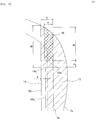
- the upper layer side joint area 15 is, as illustrated in FIG. 6 , with respect to the towel longitudinal direction, formed up to the end edge of the towel with a position toward the towel end portion by an interval E from the end edge of the non-joint area 14 as a base. Further, the upper layer side joint area 15 is formed with a width F narrower than a width T of the upper layer cuff surface 7b with respect to the towel width direction.
- the base 15a in the towel longitudinal direction of the upper layer side joint area 15 is disposed at a position further toward the end portion than the end edge 14a of the non-joint area 14, since a tip (free end) of a portion that works as the skin-abutting surface Gd on the upper layer side tends to incline high on the skin side and the skin-abutting surface Gd tends to fit along the skin at the time of standing-up of the solid gather G, the solid gather G is blocked from falling down to the inside of the solid gather G.
- the upper layer side joint area 15 is formed such that an end portion of the outside in the towel width direction locates at a tip of the upper layer side cuff surface 7b in the illustrated embodiment, but may be formed at an optional position as long as it is within the width of the upper layer side cuff surface 7b. Specific dimensions of the respective portions will be described in detail below.
- the skin-abutting surface Gd is preferable to be formed such that, with the side edge 4a of the absorber 4 as a base, a width S' of a portion that extends outward becomes larger than a width R of a portion that intervenes at a position overlapping with the absorber 4 (S' > R).
- a ratio of S' : R is preferable to be set at about 2: 1.
- a method of adjusting the width R of the inner side is performed by adjusting a position of the inside edge portion 13a because the inside elastic member 8 moves substantially on the inside edge portion 13a of the lower layer side joint area 13 in the standing state.
- a height (X + Y) of the standing wall Gc of the solid gather G is preferable to be set smaller than a width (Z + U) of the skin-abutting surface Gd.
- a contact area with the skin is preferable to be made as large as possible because the skin-abutting surface Gd has a portion that comes into close contact with the skin to block the leakage of the body liquid. Therefore, by defining a height of the standing wall Gc appropriate from a relationship with a width of the skin-abutting surface Gd, the solid gather G that does not cause the leakage and is excellent in the wearing feeling can be formed.
- a filamentous elastic extendable member is preferably used as the inside elastic member 8 and outside elastic member 9.
- Such filamentous elastic extendable members each is disposed inside of the double sheets of the side nonwoven fabric 7 in a predetermined elongated state, and both ends or appropriate positions in the longitudinal direction are fixed.
- a rate of extension (tension) of the filamentous elastic extendable member is preferably set to 120 to 160% (with a natural state as 100%, an extension rate from this state is 1.2 times to 1.6 times) .
- the tension of the outside elastic member 9 is preferably set to the same or more than the tension of the inside elastic member 8, specifically, is set higher by 0 to 20% .
- a diameter of the filamentous elastic extendable member is preferable to be about 310 to 610 dtex, the diameters of inside elastic member 8 and the outside elastic member 9 may be the same or may be different.
- the extension force (tension) of the outside elastic member 9 can be set higher than the contractile force of the inside elastic member 8.
- the inside elastic member 8 and outside elastic member 9 are preferable not to be fixed to the side nonwoven fabric 7 (in a natural state without application of the tension) in the range of about 10 mm each from the both end portions in the sanitary towel 1 longitudinal direction.
- the elastic member is fixed at the both ends in the longitudinal direction, the both end portions of the product tend to be bent due to the contractile force of the elastic member, and the uncomfortable feeling tends to be generated during wearing.
- Each of the tensions of the inside elastic member 8 and outside elastic member 9 is preferable, in the relationship with the torsional strength of the absorber 4, to be about 140% (in the case of the filamentous elastic extendable member of 470 dtex) in the case of the torsional strength of the absorber 4 is about 23 to 27 gf ⁇ cm/cm.
- each of the tensions of the elastic members 8 and 9 is preferable to be about 130% (in the case of the filamentous elastic extendable member of 470 dtex).
- the torsional strength (gf ⁇ cm/cm) is the strength when the sample is twisted by 70 deg and the torsional strength 70 degree was measured using KES large scale torsion tester.
- the KES large scale torsion tester is a large-scale torsion tester manufactured by KATO TECH Corp. (KES-YN-1-B), and the size of the sample of an absorber was set to 150 mm (in length) x 55 mm (in width), and the measurement was performed under the following test conditions.
- the lower layer side cuff surface 7a of the side nonwoven fabric 7 is joined to the constituent member on the lower layer side by the lower layer side joint area 13 from the lateral side to the cuff portion Gb, and the upper layer side cuff surface 7b is joined to the lower layer side cuff surface 7a in the upper layer side joint area 15.
- a slash shows the joint area 15 of the lower layer side cuff surface 7a and the constituent member on the lower layer side of the side nonwoven fabric 7, and the crossing slash shows the upper layer side joint area 15 of the lower layer side cuff surface 7a and the upper layer side cuff surface 7b.
- the width T of the upper layer side cuff surface 7b is preferably set to 10 to 20 mm. Since a touch area with the skin will decrease if this width T is made small, the uncomfortable feeling when wearing is alleviated, but when it is made small too much, there is a possibility that the solid gather G cannot withstand the pressure from the inner portion of the root of a leg or a motion of the body and folds back to the inside.
- the inside elastic member 8 is disposed at an intermediate portion in the width direction corresponding to the non-joint area 14, that is, between the inside edge portion 13a of the lower layer side joint area 13 and the cuff portion Gb, the distance Y from the cuff portion Gb is set to 5 mm or less, preferably set to 1 to 4 mm, the outside elastic member 9 is disposed in the intermediate portion in the width direction of the outside extended stock 7c portion, that is, between the side edge 4a of the absorber 4 and the end portion Ga, the distance Z from the end portion Ga is set to 5 mm or less, preferably to 1 to 4 mm.
- the interval U between the inside elastic member 8 and the outside elastic member 9 is desirable to be set to 6 to 15 mm. It is desirable to provide the distance Y described above in order to form the standing wall Gc of the solid gathers G, and the outside elastic member 9 is desirable to be provided with the distance Z described above rather than disposing the end portion Ga in order to alleviate the stimulus of the elastic member to the skin.
- the width X of the non-joint area 14 described above is preferable to be set to 2 to 7 mm.
- the range of a towel longitudinal direction range of the non-joint area 14 is, as illustrated in FIG.5 , preferable to be provided including at least the longitudinal direction range of the body fluid discharge portion H up to near the upper layer side joint area 15 of the upper layer side cuff surface 7b.
- each portion of the upper layer side joint area 15 is, as illustrated in FIG.6 , preferable to be set such that the distance E between the end edge 14a of the non-joint area 14 and the end edge 15a of the upper layer side joint area 15 is shorter than the towel longitudinal direction length D of the upper layer side joint area 15 described above, and specifically preferable to be set to about 2 to 7 mm.
- the towel longitudinal direction length D of the upper layer side joint area 15 described above is to be set shorter than the distance B from the towel longitudinal direction end portion to the non-joint region 14, and preferable to be set to about 20 to 45 mm.
- the distance B described above is preferable to be about 30 to 50 mm.
- the width F of the upper layer side joint region 15 is preferably set smaller than the width T of the upper layer side cuff surface 7b by disposing, as illustrated in the drawing, toward the end portion Ga by remaining slight non-joint region on the cuff portion Gb side than by disposing over an entire width T of the upper layer side cuff surface 7b.
- the width F of the specific upper layer side joint area 15 described above is preferably set to 8 to 18 mm.
- the width S of the extended stock 7c of the upper layer side cuff surface 7b in the folded state of the solid gathers G is preferably set to about 40 to 60% of the width (Z + U) of a portion that works as the skin-abutting surface Gd at the time of standing-up.
- the skin-abutting surface Gd protrudes from the side edge of the short to be easy to wear and the close contact between the skin-abutting surface Gd and the skin can be improved.
- the lower layer side joint area 13 described above is preferable to be formed from the side edge portion of the sanitary towel 1 to the position which overlaps with the absorber 4, as illustrated in FIG.2 and FIG.5 .
- the graphic display line of the lower layer side joint area 13 of the side edge side portion (a wing-like flap W portion and its neighborhood) of the sanitary towel 1 is omitted, but originally as illustrated in FIG.5 , it is disposed by extending to the side edge portion of the sanitary towel 1.
- the absorber 4 and the lower layer side joint area 13 are disposed so as to have an overlapping stock K.
Landscapes
- Health & Medical Sciences (AREA)
- Epidemiology (AREA)
- Heart & Thoracic Surgery (AREA)
- Engineering & Computer Science (AREA)
- Biomedical Technology (AREA)
- Vascular Medicine (AREA)
- Life Sciences & Earth Sciences (AREA)
- Animal Behavior & Ethology (AREA)
- General Health & Medical Sciences (AREA)
- Public Health (AREA)
- Veterinary Medicine (AREA)
- Fluid Mechanics (AREA)
- Physics & Mathematics (AREA)
- Absorbent Articles And Supports Therefor (AREA)
- Orthopedics, Nursing, And Contraception (AREA)
Abstract
Description
- The present invention relates to a sanitary towel that mainly absorbs menstrual blood, vaginal discharge or the like, in more detail, relates to a thin sanitary towel provided with solid gathers each standing on a skin side at both sides of a front side.
- In this kind of sanitary towel, due to requirements of, in addition to being free from an uncomfortable feeling, being excellent in mountability, and being unobvious, being transportable, being excellent in housing properties, and being efficient in logistics and source saving, an effort to make the sanitary towel thin and compact has progressed. However, in such a thin sanitary towel, in order not to damage the mountability, generally, the solid gathers are not provided. Therefore, there tends to occur a gap between the towel and the skin, and the lateral leakage of menstrual blood and body liquid such as urine was likely to occur.
- As the solid gather, various forms have been developed, and there are many technical literatures relating to this. For example, in the following
Patent Literature 1, a solid gather is disclosed in which, when a side nonwoven fabric is disposed in the intermediate portion in a height direction with a plurality of elastic expandable members, adhered to an absorber side in a state in which front and back end portions are laminated by folding in a Z shape in a cross-section, the solid gather stands-up on a front side while forming a pocket with an opening directed to an inside in an L-shaped cross section with a site where the elastic expandable members are disposed as a bending point. Further, similarly inPatent Literature 1, a solid gather that stands-up simply in line by adhering to the absorber side in a state where front and back end portions of the side nonwoven fabric are folded back outward is disclosed. - Further, in the following
Patent Literature 2, an absorbing article is disclosed in which an elastic material that is disposed along a free end and exhibits an elastic contractile force and an elastic material that forms a contract action line approaching from a base end side to a free end side as goes from both end sides in a vertical direction of the leakage blocking side wall to an intermediate position in a vertical direction are disposed, and both end portions in the vertical direction of the leakage blocking side wall are joined to a liquid receiving side surface of which free ends are directed to the outside in a width direction. - Further, in the following
Patent Literature 3, a sanitary towel in which a leakage-blocking wall is joined to a front sheet along a longitudinal direction above an absorber and includes a standing portion that stands up during use with the joint portion as a base point and a body side covering portion that extends externally in a width direction from the joint portion and covers a side surface portion of an absorptive body is disclosed. -
- Patent Literature 1:
JP 2004-290498 A - Patent Literature 2:
JP 3847046 - Patent Literature 3:
JP 2011-120764 A - As a solid gather that is used in commercially available sanitary towels, the solid gather that has an L-shaped cross section or a linear cross section, which are described in
Patent Literature 1, are general. However, since the sanitary towel with the L-shaped cross section has to be laminated by folding a side nonwoven fabric in a Z-shaped cross section, there were problems that a thickness increased to result in being incapable of achieving thinning and an uncomfortable feeling occurring during wearing to result in damaging features of the thin sanitary towel. Further, in a linear solid gather obtained by externally folding back the side nonwoven fabric only once, a standing height is insufficient and a gap tends to occur between the sanitary towel and the skin, and further, a standing wall portion for blocking the body liquid from flowing sideward was difficult to form. - Further, as described in
Patent Literature 2, in the case of the solid gather in which a width of a skin abutting surface in which an elastic material is disposed in a bending manner along a solid gather longitudinal direction changes, and in the case of a solid gather that stands up in a T-shaped cross section as described inPatent Literature 3, there was a fear that the clothing comfort may be degraded or that thinning may not be attained. - Still further, while a sanitary towel that has a certain degree of absorber thickness like a general sanitary towel has a structure that can absorb and hold the body liquid in a wide range of the absorber by diffusing in the inside of the absorber after the body liquid is absorbed by the absorber, in the case of a thin sanitary towel, since a high water-absorbing resin is contained at a high density in the absorber, a ratio of the body liquid that diffuses the inside of the absorber is low, and after the body liquid diffuses over a surface of the sanitary towel, the body liquid is absorbed and held by the absorber. Therefore, in the case of the thin sanitary towel in particular, since it is important to secure a surface portion effective for absorbing the body liquid over a wide range, it is necessary to avoid a situation in which the solid gather falls down toward the inside during wearing to narrow a surface width effective for absorbing the body liquid. In this point, in the case of the solid gather having the L-shaped cross section described in
Patent Literature 1, the solid gather described inPatent Literature 2, in which a width of the skin-abutting surface portion of the standing-up proximal end becomes narrower in a groin portion, and the solid gather having the T-shaped cross section described inPatent Literature 3, there was a fear that, due to pressure from the inside portion of a base of leg and movement of the leg, the skin-abutting portion of the standing-up proximal end of the solid gather tends to fall down to the inside and there is a fear that the surface width effective for absorbing the body liquid may be narrower. - In this connection, a main item of the present invention is to provide a sanitary towel provided with a solid gather that, even in a thin sanitary towel, is free from an uncomfortable feeling during wearing, is high in a body liquid blocking effect, and blocks falling down to the inside during wearing.
- As the present invention according to
claim 1 for solving the above-described problems, a sanitary towel in which an absorber is disposed at least on a front side of an impervious back sheet and a solid gather is formed along a longitudinal direction of each of front side both side portions is characterized in that: - the solid gather is, in a folded state, provided with a non-joint area that is not joined to a constituent member on a lower layer side in a longitudinal direction range containing at least a body liquid discharging portion of double sheets folded back on a center side in a width direction and in the proximity portion of a cuff portion, and, an elastic member is disposed along a longitudinal direction on the sheet on an upper layer side of an intermediate portion in a width direction corresponding to the non-joint area;
- both the double sheets are formed to an end edge of the sanitary towel with a position further toward the end edge of the sanitary towel than the end edge of the non-joint area as a base with respect to the sanitary towel longitudinal direction, and are joined in an upper layer side joint area formed with a narrower width than a sheet width on an upper side with respect to the sanitary towel width direction; and
- the solid gather is configured such that, by standing up on a skin side with an outside edge portion of the non-joint area as a base in a standing state, acts as a standing wall in which a portion between from the elastic member to the outside edge portion of the non-joint area protrudes from a front side of the absorber, and the outside portion from the elastic member acts as a skin-abutting surface at the time of wearing, and a portion that works as the skin-abutting surface moves further toward the outside in the sanitary towel width direction in the standing state than the folded state.
- According to the present invention described in
claim 1, firstly, in a folded state of the solid gather before wearing, a structure is provided, in which a double sheet structure folded back on a center side in the width direction is formed, a non-joint area that is not joined to the constituent member (the absorber, the impervious back sheet and the like) on a lower layer side in the longitudinal direction range including at least the body liquid discharging portion and in the proximity portion of the cuff portion of the double sheets is provided, and the elastic member is disposed along the longitudinal direction in an intermediate portion in the width direction corresponding to the non-joint area. Further, the double sheets are formed to the end edge of the sanitary towel with a position further toward the end portion of the sanitary towel than the end edge of the non-joint area as a base with respect to the sanitary towel longitudinal direction, and are joined in an upper side joint area formed with a narrower width than a sheet width on the upper layer side with respect to the sanitary towel width direction. - In a state where the solid gather is raised when wearing such a sanitary towel, when the solid gather stands up on the skin side with the outside edge portion of the non-joint area as a base, a portion between from the elastic member to the outside edge portion of the non-joint area acts as a standing wall that protrudes from a surface side of the absorber when the cuff state is released and an outside portion from the inside elastic member acts as the skin abutting surface when wearing. Here, since the elastic member is disposed in the intermediate portion in the width direction corresponding to the non-j oint area, when raised with the outside edge portion of the non-joint area as the base by the contraction of the elastic member, the elastic member is pulled in the outside edge portion direction of the non-joint area, and a portion that acts as the skin-abutting surface is configured such that the standing-up state moves further outward in the sanitary towel width direction than the folded state.
- Therefore, when wearing the sanitary towel, the risk of the skin-abutting surface of the solid gather falling down toward the inside is largely reduced, the surface width of the absorber effective for absorbing the body liquid may be widely secured, and even with the thin sanitary towel, high absorbance may be secured. Further, since a cross sectional shape of the solid gather forms a standing wall in which, with the inside elastic member as a bending point, an absorber side from the bending point protrudes from a surface side of the absorber, the blocking effect of the body liquid can be secured by the standing wall, and the lateral leakage can be blocked. Further, since an outside extended stock extended outward than a side edge of the absorber is disposed on a cuff surface on an upper side of the solid gather and, the skin-abutting surface is configured to move outward in the sanitary towel width direction in a standing state than in the folded state, the skin-abutting surface of the solid gather runs off outside of the side edge of a short to be easy to wear when wearing the sanitary towel, and a risk that the solid gather falls down on the inside by the pressure from the inside of a root portion of the leg or the movement of the leg is largely reduced. Further, since the solid gather is formed from a sheet of a two-layer structure including a lower layer side cuff surface and an upper layer side cuff surface in a folded state, a thickness of the solid gather can be made thinner and the uncomfortable feeling when wearing can be made difficult to feel.
- Further, an angle by which the skin-abutting surface contacts with the skin is adjusted or the uncomfortable feeling when wearing is reduced by forming the upper layer joint area in which the double sheets are joined each other in a predetermined region. Specifically, the double sheets are formed up to a towel end edge with a position toward the towel end portion than an end edge of the non-joint area as a base with respect to a towel longitudinal direction and are joined in the upper layer side joint area formed with a narrower width than a sheet width on the upper layer side with respect to a towel width direction. By disposing the base in the towel longitudinal direction of the upper layer side joint area at a position further toward the end portion than the end edge of the non-joint area, since a tip end (free end) of a portion that works as the skin-abutting surface on the upper layer side tends to incline toward the skin side and the skin-abutting surface tends to fit along the skin, the solid gather may be blocked from falling down on the inside of the solid gather. Further, when a joint area that may cause degradation of the skin touch by curing is formed into a small area by forming the width in the towel width direction of the upper layer side joint area with a narrower width than the sheet width of the upper layer side, the uncomfortable feeling when wearing is alleviated.
- As a present invention according to
claim 2, a sanitary towel in which an absorber is disposed at least on a surface side of an impervious back sheet and a solid gather is formed along a longitudinal direction of each of front both sides is characterized in that: - when the solid gather is folded back in a folded state to a lateral side at a folding back portion disposed at a position where a sheet extended in a center side direction from a lateral side of the sanitary towel overlaps the absorber, a lower layer side joint area that has a lower layer side cuff surface and an upper layer side cuff surface and in which the lower layer side cuff surface and a constituent member on a lower layer side of the lower layer side cuff surface are joined is formed over a predetermined area in a center side direction from the lateral side of the sanitary towel, a non-joint area that is in a longitudinal direction range including at least a body liquid discharging portion and in which the lower layer side cuff surface and the constituent member on a lower layer side are joined in the vicinity portion of the cuff portion is formed, an upper layer side joint area in which the upper layer side cuff surface and the lower layer side cuff surface are joined in the both end portions in the sanitary towel longitudinal direction is formed, an outside extended stock in which the outside in the width direction of the upper layer side cuff surface is extended outside than an end edge of the absorber is disposed on the upper layer side cuff surface, an inside elastic member is disposed along the longitudinal direction in an intermediate portion in a width direction corresponding to the non-joint area of the upper layer side cuff surface, and further outside in the width direction, an outside elastic member is disposed along the longitudinal direction,
- the upper layer side joint area is formed to the end edge of the sanitary towel with a position further toward an end portion of the sanitary towel than the end edge of the non-joint area as a base relative to the sanitary towel longitudinal direction, and is formed with a narrower width than a width of the upper layer side cuff surface with respect to the sanitary towel width direction, and
- the solid gather, by standing up on a skin side with an inside edge portion of the lower layer side joint area as a base in a standing state, acts as a standing wall from which a portion from the inside elastic member to the inside edge portion of the lower layer side joint area protrudes from a front side of the absorber, and an outside portion of the inside elastic member acts as an abutting surface at the time of wearing, and a portion that works as the abutting surface is configured to move to the outside in the sanitary towel width direction in the standing state than in the folded state. The present invention defines the structure of a solid gather more specifically.
- As the present invention according to
claim 3, the sanitary towel according to any one ofclaims - In the invention according to
claim 3, as the thin sanitary towel, a thickness is set to 3 mm or less (a thickness of a portion excluding the center-high-portion when the center-high-portion of the absorber is formed in a portion corresponding to the body liquid discharging portion). - As the present invention according to
claim 4, the sanitary towel according to any one ofclaims 1 to 3 is provided, in which, in the standing state of the solid gather, the skin-abutting surface is formed such that the width of the portion extending outward of the side edge of the absorber is larger than the width of a portion that intervenes in a position that overlaps with the absorber. - According to the present invention of the
claim 4, in the standing state of the solid gather, as a rate with which the abutting-surface is extended outward of the side edge of the absorber, when the width of a portion that extends outward is formed larger than the width of a portion that intervenes in the position overlapping with the absorber, the skin-abutting surface is blocked from falling down on the inside. - As the present invention according to
claim 5, the sanitary towel according to any one ofclaims 2 to 4 in which the outside elastic member is disposed in an intermediate portion in the width direction of the outside extended stock portion of the upper layer side cuff surface is provided. - In the invention according to
claim 5, a disposition position of the outside elastic member is defined. The outside elastic member is preferably disposed in an intermediate portion in the width direction of the outside extended stock portion of the upper layer side cuff surface. By this, the elastic member is disposed over a wide range of the skin-abutting surface and a contact surface with the skin increases to be able to block the leakage. - As the present invention according to claim 6, the sanitary towel according to any one of
claims 2 to 5 in which the tension of the outside elastic member is set equal to or larger than the tension of the inside elastic member is provided. - In the invention according to claim 6, by setting the tension of the outside elastic member equal to or larger than the tension of the inside elastic member, the skin-abutting surface of the solid gather tends to stand in a cross-sectional shape inclined toward the inside, and the adhesion with the skin may be further improved.
- As the present invention according to
claim 7, the sanitary towel according toclaims 2 to 6 in which the lower layer side joint area is formed from the lateral side of the sanitary towel up to the position that overlaps with the absorber is provided. - In the invention according to
claim 7, when a range of the joint area that joins the lower layer side cuff surface to the lower layer side constituent member is formed from a lateral side of the sanitary towel up to a position that overlaps with the absorber, a standing wall of the solid gather that stands up with the inside edge portion of the joint area as a base is formed in the intervening position of the absorber, thus the body liquid that is blocked by the standing wall is made readily absorbable. - As detailed in the above, according to the present invention, even in the thin sanitary towel, the sanitary towel provided with the solid gather that is free from the uncomfortable feeling when wearing, is high in the body liquid blocking effect, and can block the falling on the inside when wearing can be provided.
-
- [
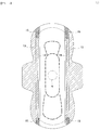
FIG.1] FIG. 1 is a partially broken development view of asanitary towel 1 according to the present invention. - [
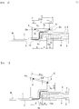
FIG. 2] FIG. 2 is a cross-sectional view illustrating a folded state of a solid gather G (II-II line arrow view ofFIG. 1 ). - [
FIG. 3] FIG. 3 is a cross-sectional view illustrating a standing-up state of the solid gather G. - [
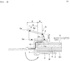
FIG.4] FIG. 4 is a cross-sectional view illustrating a wearing state to a short of thesanitary towel 1. - [
FIG.5] FIG. 5 is a development view illustrating a joint area or the like of a sidenonwoven fabric 7. - [
FIG. 6] FIG. 6 is an enlarged view of a longitudinal direction end portion. - Hereinafter, embodiments of the present invention will be detailed with reference to the drawings.
- A
sanitary towel 1 according to the present invention includes, as illustrated inFig. 1 andFIG. 2 , animpervious back sheet 2 made of a polyethylene sheet, a polypropylene sheet, or the like, apervious front sheet 3 that speedily transmits menstrual blood, vaginal discharge, or the like, anabsorber 4 that is interposed between the bothsheets crape paper 5 surrounding theabsorber 4 for holding a shape and improving the diffusivity of theabsorber 4, and sidenonwoven fabrics absorber 4, at upper and lower end edge portions, outer peripheries of theimpervious back sheet 2 and thepervious front sheet 3 are joined by an adhesive such as hot melt or the like or a joining means such as heat seal, or the like, further, at both side edge portions, theimpervious back sheet 2 extended further sideward than theabsorber 4 and the sidenonwoven fabric 7 are joined by an adhesive such as hot melt or the like or a joining means such as heat seal, or the like, and wing-like flaps W and W protruding sideward are formed from a composite sheet portion made of theseimpervious back sheet 2 and the sidenonwoven fabric 7. - The
sanitary towel 1 according to the present invention is preferably made into a thin towel of which thickness is set to 3 mm or less, and, when, though not shown in the drawing, a center-high portion of the absorber is formed in a portion corresponding to a body liquid discharging portion and in the circumference thereof, a thickness of a portion excluding the center-high portion is preferably set to 3 mm or less. Further, a towel for daytime use having a total length in the longitudinal direction of 20 to 30 cm is targeted because it is assumed to be able to respond to the movement of legs when a wearer is walking in the daytime or the like. - Hereinafter, a structure of the
sanitary towel 1 will be further detailed. - As the
impervious back sheet 2, sheet materials having at least the water shieldability such as sheets of olefinic resin such as polyethylene, polypropylene or the like are used. However, other than these, laminated nonwoven fabric obtained by laminating the nonwoven fabric on a polyethylene sheet or the like, further, a nonwoven fabric sheet (In this case, the waterproof film and the nonwoven fabric constitute the impervious back sheet.) in which the imperviousness is substantially secured by intervening a waterproof film and the like can be used. In recent years, materials having the moisture permeability tend to be used from the viewpoint of steaming blocking. The water shieldable and moisture permeable sheet material is a microporous sheet obtained by monoaxially or biaxially stretching after molding a sheet by melt kneading an inorganic filler in the olefinic resin such as polyethylene, polypropylene or the like. - Then, as the
pervious front sheet 3, a porous or nonporous nonwoven fabric is preferably used. As a raw material fiber that constitutes the nonwoven fabric, other than synthetic fibers such as olefin system such as polyethylene, polypropylene or the like, polyester system, polyamide system, or the like, recycled fiber such as rayon, cupra, or the like, and natural fiber such as cotton or the like may be used, and the nonwoven fabric obtained according to an appropriate processing method such as the span race method, the span bond method, the thermal bond method, the melt-blown method, the needle punch method or the like may be used. Among these processing methods, the span race method is excellent in the flexibility, the span bond method is excellent in being rich in the drape, and the thermal bond method and an air through method are excellent in being bulky and soft. - When the center-high portion of the absorber is formed in the groin region, an
oblong embossing 10 is formed on a surface of thepervious front sheet 3 to hold the center-high portion at a predetermined position, to make clearly swell on a front side, to confine the absorbed body liquid and the like. Further, in a front side region, a substantially inverseU-shaped embossing 11 in which both ends of a circular embossing are extended as they are to the groin region side is formed, and, in a back region, a substantiallyU-shaped embossing 12 in which both ends of a circular embossing are extended as they are to the groin region side is formed. - Although the
pervious front sheet 3 is preferable to be disposed as far as possible, it is possible not to dispose for further improving the thinning of the towel. When thepervious front sheet 3 is not disposed, it is preferable to usecrape paper 5 or a nonwoven fabric to surround theabsorber 4 or to cover only a front side of theabsorber 4. - As the
absorber 4 that is interposed between theimpervious back sheet 2 andfront sheet 3, one obtained by mixing a superabsorber resin in a pulp, or one obtained by mixing chemical fibers in the pulp and by further mixing the superabsorber resin is used. Theabsorber 4 is, as illustrated in the drawing, desirably surrounded bycrepe paper 5 for maintaining a shape, speedily diffusing the menstrual blood or the like, and blocking the once absorbed menstrual blood or the like from turning back. As the pulp described above, what are made of cellulose fibers such as chemical pulp, molten pulp or the like obtained from wood, or artificial cellulose fibers such as rayon, acetate or the like are cited, and softwood pulp is preferably used than hardwood pulp from the viewpoint of function and cost. - Further, the
absorber 4 may be mixed with the synthetic fibers. As the synthetic fibers, for example, polyolefin system such as polyethylene, polypropylene, or the like, polyester system such as polyethylene terephthalate, polybutylene terephthalate, or the like, polyamide system such as nylon, or the like, and copolymers thereof may be used, and two kinds thereof may be mixed and used. Further, also a sheath/core fiber with a high-melting point fiber as a core and a low-melting point fiber as a sheath, a side-by-side fiber, and a composite fiber such as divided fiber may be used. When the synthetic fiber is a hydrophobic fiber, it is desirable to use what is surface treated with a hydrophilizing agent for imparting affinity to the body liquid. - As the superabsorber resin, what was obtained by partially crosslinking water-swelling polymers such as polyacrylate crosslinked products, self-crosslinked polyacrylates, saponified products of acrylic acid ester-vinyl acetate copolymer crosslinked products, crosslinked products of isobutylene-maleic anhydride copolymers, polysulfonate crosslinked products, polyethylene oxide, polyacrylamide or the like are cited. Among these, acrylic acid or acrylate system excellent in an amount of water absorption and a water absorption rate is preferable. In the superabsorber resin having the water absorption performance described above, in the production process, the water absorption power and the water absorption rate can be controlled by adjusting the crosslinking density and the crosslinking density gradient. A content of the superabsorber resin is desirable to be set to 10 to 60% of a weight of the absorber. When the content of the superabsorber resin is less than 10%, sufficient absorbing power cannot be imparted, and when the content exceeds 60%, there is no entanglement between pulp fibers, and the sheet strength is degraded and break or crack tends to occur.
- As in the present embodiment, when the
crepe paper 5 surrounding theabsorber 4 is disposed, resultantly, thecrepe paper 5 intervenes between thepervious front sheet 3 and theabsorber 4, and the body liquid is rapidly diffused by thecrepe paper 5 excellent in the absorbability, and, at the same time, the menstrual blood or the like is blocked from turning back. Incidentally, in order to make the towel thinner, thecrepe paper 5 may not be disposed or may be disposed so as to cover only the front side not by surrounding. - As the side
nonwoven fabric 7 described above, a water-repellent-finish nonwoven fabric or a hydrophilic processing nonwoven fabric can be used from a viewpoint of the function to which importance is attached. For example, if functions, such as blocking menstrual blood, a vaginal discharge, or the like from permeating, or raising a feeling of the skin touch, are thought as important, it will be desirable to use the water-repellent-finish nonwoven fabric which is coated with a silicon system, paraffin series, alkyl chromic chloride system water repellent, or the like. If the absorptivity of the menstrual blood or the like in the wing-like flaps W and W described above is thought as important, a method of making a compound with a hydrophilic group, for example, an oxidation product of a polyethylene glycol, or the like coexist and polymerize in the manufacturing process of a synthetic fiber, or a method of treating with a metal salt like a stannic chloride and partially dissolving a surface to render porous and precipitating hydroxide of the metal is used to make the synthetic resin swell or porous, and a hydrophilic processing nonwoven fabric to which the hydrophilicity is imparted by applying a capillary action is desirably used. It is preferable to use the nonwoven fabric manufactured by SMMS, air through, and so on as a raw material. The basis weight is preferable to be about 30 to 45 g/m2. - In the inward side of the side
nonwoven fabric 7, as illustrated inFIG. 2 , the sidenonwoven fabric 7 is folded back in substantially two, in the inside of the double sheets, one or a plurality of, in the illustrated example, two of the insideelastic member 8 and the outsideelastic member 9 in which both ends or an appropriate position in the longitudinal direction are fixed at an intermediate portions in a height direction are disposed, and the solid gathers G and G in which the double sheet portion is erected on a front side by its contractile force are formed. The structure of the solid gather G will be more specifically described below. - When the solid gather G is, in a folded state, as illustrated in
FIG. 2 , folded back on a lateral side at a cuff portion Gb disposed at a position where the side nonwoven fabric 7 extended in a central side direction from a lateral side of the towel, a lower layer side joint area 13 that has a lower layer side cuff surface 7a and an upper layer side cuff surface 7b and in which the lower layer side cuff surface 7a and a constituent member on the further lower layer side (the pervious front sheet 3, the impervious back sheet 2 or the like) are joined over a predetermined region in a direction from a lateral side to the center side of the towel is formed, a non-joint area 14 in which the lower layer side cuff surface 7a and the constituent member on the lower layer side are not joined in the longitudinal direction range including at least the body liquid discharging portion H and in the vicinity of the cuff portion Gb is formed, and an upper layer side joint area 15 (seeFIG. 5 ) in which the upper layer side cuff surface 7b and the lower layer side cuff surface 7a are joined at both ends in the towel longitudinal direction is formed, on the upper layer side cuff surface 7b, an outside extended stock 7c in which the outside in the width direction of the upper layer side cuff surface 7b is extended outward of the side edge 4a of the absorber 4 on the upper layer side cuff portion 7b is disposed, the inside elastic member 8 is disposed along the longitudinal direction at an intermediate portion in a width direction corresponding to the non-joint area 14 of the upper layer side cuff surface 7b, and on more outside than this in the width direction, preferably the outside elastic member 9 is disposed along the longitudinal direction in the intermediate portion in the width direction of the outside extended stock 7c portion. - That is, as illustrated in
FIG. 2 , in the sidenonwoven fabric 7, a portion from a lateral side to a position of distance K inward of theside edge 4a of theabsorber 4 of the lower layerside cuff surface 7a is joined to the constituent member on the lower layer side by the lower layer sidejoint area 13 in the longitudinal direction range including at least the body liquid discharging portion H, a portion from theinside edge portion 13a of the lower layer sidejoint area 13 to a position of distance X inward is made anon-joint area 14, the cuff portion Gb is formed at this position, thus, a section of a distance T up to an edge portion Ga from Gb is made the upper layerside cuff surface 7b. In the upper layerside cuff surface 7b, the outsideextended stock 7c in which the end portion Ga side is extended by a width S on the outside in the width direction than aside edge 4a of theabsorber 4 is formed. In the elastic member disposed on the upper layerside cuff surface 7b, the insideelastic member 8 is disposed at a position distanced outward by a distance Y from the cuff portion Gb, and the outsideelastic member 9 is disposed at a position distanced inward by a distance Z. A distance between the insideelastic member 8 and the outsideelastic member 9 is U. - When thus folded solid gather G, in a standing state, as illustrated in
FIG. 3 , stands up on the skin side with theinside edge portion 13a (outside edge portion of the non-join area 14) of the lower layer sidejoint area 13 as a base, a portion between from the insideelastic member 8 to theinside edge portion 13a of the lower layer side joint area 13 (section X + Y) and works as a standing wall Gc protruding from a front side of the absorber 4 (pervious front sheet 3) when the cuff portion Gb is relieved, and with the insideelastic member 8 as a bending point, an outside portion (section Z + U) of the insideelastic member 8 inclines at an inclination angle that increases toward the outward side and works as a skin-abutting surface Gd that contacts with a skin of a wearer during wearing. Then, as illustrated inFIG. 4 , a portion that works as the skin-abutting surface Gd is configured to move outward in the towel width direction in the standing state than in the folded state. That is, a distance in the width direction from aside edge 4a of theabsorber 4 to an end portion Ga of the upper layerside cuff surface 7b (an amount of protrusion of the absorber from theside edge 4a) is configured such that S' of the standing state is larger than S of the folded state (S < S') . - As a mechanism by which the portion that works as the skin-abutting surface Gd moves outward in the towel width direction in the standing state than in the folded state, since the inside
elastic member 8 is disposed in the intermediate portion in the width direction of a portion corresponding to thenon-joint area 14 of the upper layerside cuff surface 7b, that is, is disposed inward of theinside edge portion 13a of the lower layer sidejoint area 13, when standing-up with theinside edge portion 13a of the lower layer sidejoint area 13 as a base by the contractile force of the insideelastic member 8, a force that pulls the insideelastic member 8 obliquely upward in aninside edge portion 13a direction of the lower layer sidejoint area 13. - When wearing the
sanitary towel 1 in which the gather G like this is formed on a short, as illustrated inFIG. 4 , when the wing-like flap W is folded back along the side edge of substantially theabsorber 4 and fixed so as to circumvolute the side edge of the short SH, the skin-abutting surface Gd of the solid gather G moves outward in the width direction by the contractile force of the insideelastic member 8 as described above, therefore, a risk that the skin-abutting surface Gd falls down to the inside is largely reduced and a surface width of theabsorber 4 effective for absorbing the body liquid can be secured wide, and even the thinsanitary towel 1 can secure high absorptivity. Further, since the standing wall Gc protruding from a front side of theabsorber 4 is formed in an inside portion in a standing state of the solid gather G, the effect of blocking the body liquid from diffusing outward can be secured and the body liquid can be blocked from laterally leaking. - Further, since the outside
extended stock 7c that is extended outward of theside edge 4a of theabsorber 4 is disposed on the upper layerside cuff surface 7b of the solid gather G, and the skin-abutting surface Gd is configured to move outward in the towel width direction in the standing state than in the folded state, the case where the skin-abutting surface Gd of the solid gather G is worn in a state protruding outside of the side edge of the short SH becomes frequent when wearing the towel, and a rate by which the solid gather G falls down inward by the pressure from the inside of the root portion of the leg or the movement of the leg is largely reduced. - Still further, a thickness of the solid gather G can be made thinner and the uncomfortable feeling when wearing becomes difficult to feel because the solid gather G becomes a sheet of two-layer structure made from the lower layer
side cuff surface 7a and the upper layerside cuff surface 7b in the folded state. - The upper layer side
joint area 15 is, as illustrated inFIG. 6 , with respect to the towel longitudinal direction, formed up to the end edge of the towel with a position toward the towel end portion by an interval E from the end edge of thenon-joint area 14 as a base. Further, the upper layer sidejoint area 15 is formed with a width F narrower than a width T of the upperlayer cuff surface 7b with respect to the towel width direction. Thus, when thebase 15a in the towel longitudinal direction of the upper layer sidejoint area 15 is disposed at a position further toward the end portion than theend edge 14a of thenon-joint area 14, since a tip (free end) of a portion that works as the skin-abutting surface Gd on the upper layer side tends to incline high on the skin side and the skin-abutting surface Gd tends to fit along the skin at the time of standing-up of the solid gather G, the solid gather G is blocked from falling down to the inside of the solid gather G. Further, when a width F in the towel width direction of the upper layer sidejoint area 15 is formed narrower than a width T of the upper layerside cuff surface 7b, a joint area that causes deterioration of the skin touch by curing is formed into a small area, unpleasant sensation when wearing is alleviated. Incidentally, the upper layer sidejoint area 15 is formed such that an end portion of the outside in the towel width direction locates at a tip of the upper layerside cuff surface 7b in the illustrated embodiment, but may be formed at an optional position as long as it is within the width of the upper layerside cuff surface 7b. Specific dimensions of the respective portions will be described in detail below. - As illustrated in
FIG. 4 , in the standing state of the solid gather G, the skin-abutting surface Gd is preferable to be formed such that, with theside edge 4a of theabsorber 4 as a base, a width S' of a portion that extends outward becomes larger than a width R of a portion that intervenes at a position overlapping with the absorber 4 (S' > R). When the skin-abutting surface Gd is disposed at a position that satisfies such a relationship, the skin-abutting surface Gd can be further blocked from falling down to the inside. A ratio of S' : R is preferable to be set at about 2: 1. A method of adjusting the width R of the inner side is performed by adjusting a position of theinside edge portion 13a because the insideelastic member 8 moves substantially on theinside edge portion 13a of the lower layer sidejoint area 13 in the standing state. - Further, as illustrated in
FIG. 3 , a height (X + Y) of the standing wall Gc of the solid gather G is preferable to be set smaller than a width (Z + U) of the skin-abutting surface Gd. When the height (X + Y) of the standing wall Gc is too high, the risk of falling down on the inside becomes higher and, when a gap between a towel surface and the skin is small, the standing wall Gc collapses to tend to cause twists or wrinkles and to generate uncomfortable feeling when wearing. On the other hand, a contact area with the skin is preferable to be made as large as possible because the skin-abutting surface Gd has a portion that comes into close contact with the skin to block the leakage of the body liquid. Therefore, by defining a height of the standing wall Gc appropriate from a relationship with a width of the skin-abutting surface Gd, the solid gather G that does not cause the leakage and is excellent in the wearing feeling can be formed. - As the inside
elastic member 8 and outsideelastic member 9, a filamentous elastic extendable member is preferably used. Such filamentous elastic extendable members each is disposed inside of the double sheets of the sidenonwoven fabric 7 in a predetermined elongated state, and both ends or appropriate positions in the longitudinal direction are fixed. A rate of extension (tension) of the filamentous elastic extendable member is preferably set to 120 to 160% (with a natural state as 100%, an extension rate from this state is 1.2 times to 1.6 times) . Further, the tension of the outsideelastic member 9 is preferably set to the same or more than the tension of the insideelastic member 8, specifically, is set higher by 0 to 20% . Thus, since the skin-abutting surface Gd is formed at an inclination angle in which the outsideelastic member 9 is disposed is relatively higher than the inside on the skin side in the standing state of the solid gather G, the skin-abutting surface Gd tends to more easily follow the body, and the close contact with the skin can be further improved. A diameter of the filamentous elastic extendable member is preferable to be about 310 to 610 dtex, the diameters of insideelastic member 8 and the outsideelastic member 9 may be the same or may be different. When the diameter of the outsideelastic member 9 that is relatively larger than the diameter of the insideelastic member 8 is used, even when rates of extension of the both are set to equal, the extension force (tension) of the outsideelastic member 9 can be set higher than the contractile force of the insideelastic member 8. - The inside
elastic member 8 and outsideelastic member 9 are preferable not to be fixed to the side nonwoven fabric 7 (in a natural state without application of the tension) in the range of about 10 mm each from the both end portions in thesanitary towel 1 longitudinal direction. When the elastic member is fixed at the both ends in the longitudinal direction, the both end portions of the product tend to be bent due to the contractile force of the elastic member, and the uncomfortable feeling tends to be generated during wearing. - Each of the tensions of the inside
elastic member 8 and outsideelastic member 9 is preferable, in the relationship with the torsional strength of theabsorber 4, to be about 140% (in the case of the filamentous elastic extendable member of 470 dtex) in the case of the torsional strength of theabsorber 4 is about 23 to 27 gf·cm/cm. Further, when theabsorber 4 has weak stiffness such that the torsional strength is about 19 to 23 gf·cm/cm, in order to block theabsorber 4 from shrinking due to contraction of the elastic member to result in degradation of the close contact with a skin of the skin-abutting surface Gd of the solid gather G, each of the tensions of theelastic members - The torsional strength (gf·cm/cm) is the strength when the sample is twisted by 70 deg and the torsional strength 70 degree was measured using KES large scale torsion tester. The KES large scale torsion tester is a large-scale torsion tester manufactured by KATO TECH Corp. (KES-YN-1-B), and the size of the sample of an absorber was set to 150 mm (in length) x 55 mm (in width), and the measurement was performed under the following test conditions.
- Measurement chuck portion: edges of upper chuck and lower chuck are set in accordance with the edge of a sample,
- Chuck interval: 115 mm,
- SENS(recording sensitivity):2,
- Torsion angle: 7/CONTROL:7,
- SPEED: 12 cm/s, and
- Sample width: 6 cm.
- In the longitudinal direction both ends of the
sanitary towel 1, as illustrated inFIG.5 , the lower layerside cuff surface 7a of the sidenonwoven fabric 7 is joined to the constituent member on the lower layer side by the lower layer sidejoint area 13 from the lateral side to the cuff portion Gb, and the upper layerside cuff surface 7b is joined to the lower layerside cuff surface 7a in the upper layer sidejoint area 15. InFIG.5 , a slash shows thejoint area 15 of the lower layerside cuff surface 7a and the constituent member on the lower layer side of the sidenonwoven fabric 7, and the crossing slash shows the upper layer sidejoint area 15 of the lower layerside cuff surface 7a and the upper layerside cuff surface 7b. - Next, as shown in
FIG.6 , the detailed dimension of the solid gathers G, the dimension of thenon-joint area 14, and so on will be described. The width T of the upper layerside cuff surface 7b is preferably set to 10 to 20 mm. Since a touch area with the skin will decrease if this width T is made small, the uncomfortable feeling when wearing is alleviated, but when it is made small too much, there is a possibility that the solid gather G cannot withstand the pressure from the inner portion of the root of a leg or a motion of the body and folds back to the inside. - As positions of the
elastic members side cuff surface 7b, as shown inFIG.2 , the insideelastic member 8 is disposed at an intermediate portion in the width direction corresponding to thenon-joint area 14, that is, between theinside edge portion 13a of the lower layer sidejoint area 13 and the cuff portion Gb, the distance Y from the cuff portion Gb is set to 5 mm or less, preferably set to 1 to 4 mm, the outsideelastic member 9 is disposed in the intermediate portion in the width direction of the outsideextended stock 7c portion, that is, between theside edge 4a of theabsorber 4 and the end portion Ga, the distance Z from the end portion Ga is set to 5 mm or less, preferably to 1 to 4 mm. The interval U between the insideelastic member 8 and the outsideelastic member 9 is desirable to be set to 6 to 15 mm. It is desirable to provide the distance Y described above in order to form the standing wall Gc of the solid gathers G, and the outsideelastic member 9 is desirable to be provided with the distance Z described above rather than disposing the end portion Ga in order to alleviate the stimulus of the elastic member to the skin. - The width X of the
non-joint area 14 described above is preferable to be set to 2 to 7 mm. The range of a towel longitudinal direction range of thenon-joint area 14 is, as illustrated inFIG.5 , preferable to be provided including at least the longitudinal direction range of the body fluid discharge portion H up to near the upper layer sidejoint area 15 of the upper layerside cuff surface 7b. - The dimension of each portion of the upper layer side
joint area 15 is, as illustrated inFIG.6 , preferable to be set such that the distance E between theend edge 14a of thenon-joint area 14 and theend edge 15a of the upper layer sidejoint area 15 is shorter than the towel longitudinal direction length D of the upper layer sidejoint area 15 described above, and specifically preferable to be set to about 2 to 7 mm. The towel longitudinal direction length D of the upper layer sidejoint area 15 described above is to be set shorter than the distance B from the towel longitudinal direction end portion to thenon-joint region 14, and preferable to be set to about 20 to 45 mm. The distance B described above is preferable to be about 30 to 50 mm. The width F of the upper layer sidejoint region 15 is preferably set smaller than the width T of the upper layerside cuff surface 7b by disposing, as illustrated in the drawing, toward the end portion Ga by remaining slight non-joint region on the cuff portion Gb side than by disposing over an entire width T of the upper layerside cuff surface 7b. The width F of the specific upper layer sidejoint area 15 described above is preferably set to 8 to 18 mm. - As illustrated in
FIG. 2 , the width S of theextended stock 7c of the upper layerside cuff surface 7b in the folded state of the solid gathers G is preferably set to about 40 to 60% of the width (Z + U) of a portion that works as the skin-abutting surface Gd at the time of standing-up. Thus, when wearing thesanitary towel 1, the skin-abutting surface Gd protrudes from the side edge of the short to be easy to wear and the close contact between the skin-abutting surface Gd and the skin can be improved. - The lower layer side
joint area 13 described above is preferable to be formed from the side edge portion of thesanitary towel 1 to the position which overlaps with theabsorber 4, as illustrated inFIG.2 andFIG.5 . In the example shown inFIG.2 , the graphic display line of the lower layer sidejoint area 13 of the side edge side portion (a wing-like flap W portion and its neighborhood) of thesanitary towel 1 is omitted, but originally as illustrated inFIG.5 , it is disposed by extending to the side edge portion of thesanitary towel 1. In the longitudinal direction range in which thenon-joint area 14 containing at least the body fluid discharge portion H is formed, as illustrated inFIG.2 , theabsorber 4 and the lower layer sidejoint area 13 are disposed so as to have an overlapping stock K. Thus, in the standing state of the solid gathers G, since the standing wall Gc is always formed in the interposition position of theabsorber 4 as shown inFIG. 3 , the body fluid dammed up by the standing wall Gc becomes easy to be absorbed. -
- 1/SANITARY TOWEL
- 2/IMPERVIUS BACK SHEET
- 3/PERVIOUS FRONT SHEET
- 4/ABSORBER
- 5/CREPE PAPER
- 7/SIDE NONWOVEN FABRIC
- 7a/LOWER LAYER SIDE CUFF SURFACE
- 7b/UPPER LAYER SIDE CUFF SURFACE
- 7c/OUTSIDE EXTENDED STOCK
- 8/INSIDE ELASTIC MEMBER
- 9/OUTSID EELASTIC MEMBER
- 10 to 12/EMBOSSING
- 13/LOWER LAYER SIDE JOINT AREA
- 14/NON-JOINT AREA
- 15/UPPER LAYER SIDE JOINT AREA
- G/SOLID GATHERS
- Ga/END PORTION
- Gb/CUFF PORTION
- Gc/STANDING WALL
- Gd/SKIN-ABUTTING SURFACE
- W/WING-LIKE FLAP
Claims (7)
- A sanitary towel in which an absorber is disposed at least on a front side of an impervious back sheet and a solid gather is formed along a longitudinal direction of each of front side both side portions is characterized in that:the solid gather is, in a folded state, provided with a non-joint area that is not joined to a constituent member on a lower layer side in a longitudinal direction range containing at least a body liquid discharging portion of double sheets folded back on a center side in a width direction and in the proximity portion of a cuff portion, and, an elastic member is disposed along a longitudinal direction on the sheet on an upper layer side of an intermediate portion in a width direction corresponding to the non-joint area;both the double sheets are formed to an end edge of the sanitary towel with a position further toward the end edge of the sanitary towel than the end edge of the non-joint area as a base with respect to the sanitary towel longitudinal direction, and are joined in an upper layer side joint area formed with a narrower width than a sheet width on an upper side with respect to the sanitary towel width direction; andthe solid gather is configured such that, by standing up on a skin side with an outside edge portion of the non-joint area as a base in a standing state, acts as a standing wall in which a portion between from the elastic member to the outside edge portion of the non-joint area protrudes from a front side of the absorber, and the outside portion of the elastic member acts as a skin-abutting surface at the time of wearing, and a portion that works as the skin-abutting surface moves further toward the outside in the sanitary towel width direction in the standing state than the folded state.
- A sanitary towel in which an absorber is disposed at least on a front side of an impervious back sheet and a solid gather is formed along a longitudinal direction of each of front both sides is characterized in that:when the solid gather is folded back in a folded state to a lateral side at a folding back portion disposed at a position where a sheet extended in a center side direction from a lateral side of the sanitary towel overlaps the absorber, a lower layer side joint area that has a lower layer side cuff surface and an upper layer side cuff surface and in which the lower layer side cuff surface and a constituent member on a lower layer side than the lower layer side cuff surface are joined is formed over a predetermined area in a center side direction from the lateral side of the sanitary towel, a non-joint area that is in a longitudinal direction range including at least a body liquid discharging portion and in which the lower layer side cuff surface and the constituent member on a lower layer side are joined in the vicinity portion of the cuff portion is formed, an upper layer side joint area in which the upper layer side cuff surface and the lower layer side cuff surface are joined in the both end portions in the sanitary towel longitudinal direction is formed, an outside extended stock in which the outside in the width direction of the upper layer side cuff surface is extended outside of an end edge of the absorber is disposed on the upper layer side cuff surface, an inside elastic member is disposed along the longitudinal direction in an intermediate portion in a width direction corresponding to the non-joint area of the upper layer side cuff surface, and further outside in the width direction, an outside elastic member is disposed along the longitudinal direction,the upper layer side joint area is formed to the end edge of the sanitary towel with a position further toward an end portion of the sanitary towel than the end edge of the non-joint area as a base relative to the sanitary towel longitudinal direction, and is formed with a narrower width than a width of the upper layer side cuff surface with respect to the sanitary towel width direction, andthe solid gather, by standing up on a skin side with an inside edge portion of the lower layer side joint area as a base in a standing state, acts as a standing wall from which a portion from the inside elastic member to the inside edge portion of the lower layer side joint area protrudes from a front side of the absorber, and an outside portion of the inside elastic member acts as an abutting surface at the time of wearing, and a portion that works as the abutting surface is configured to move further to the outside in the sanitary towel width direction in the standing state than in the folded state.
- The sanitary towel according to any one of claims 1 and 2, wherein a thickness of a portion excluding a center-high-portion is set to 3 mm or less when the center-high-portion of the absorber is formed in a portion corresponding to the body liquid discharging portion.
- The sanitary towel according to any one of claims 1 to 3, wherein, in the standing state of the solid gather, the skin-abutting surface is formed such that the width of the portion extending outward of the end edge of the absorber is larger than the width of a portion intervening in a position that overlaps with the absorber.
- The sanitary towel according to any one of claims 2 to 4, wherein the outside elastic member is disposed in an intermediate portion in the width direction of the outside extended stock portion of the upper layer side cuff surface.
- The sanitary towel according to any one of claims 2 to 5, wherein a tension of the outside elastic member is set equal to or larger than the tension of the inside elastic member.
- The sanitary towel according to any one of claims 2 to 6, wherein the lower layer side joint area is formed from the lateral side of the sanitary towel up to the position that overlaps with the absorber.
Applications Claiming Priority (2)
| Application Number | Priority Date | Filing Date | Title |
|---|---|---|---|
| JP2013111645A JP5938368B2 (en) | 2013-05-28 | 2013-05-28 | Sanitary napkin |
| PCT/JP2014/064129 WO2014192809A1 (en) | 2013-05-28 | 2014-05-28 | Sanitary towel |
Publications (3)
| Publication Number | Publication Date |
|---|---|
| EP3005998A1 true EP3005998A1 (en) | 2016-04-13 |
| EP3005998A4 EP3005998A4 (en) | 2017-01-18 |
| EP3005998B1 EP3005998B1 (en) | 2020-01-15 |
Family
ID=51988834
Family Applications (1)
| Application Number | Title | Priority Date | Filing Date |
|---|---|---|---|
| EP14804766.5A Active EP3005998B1 (en) | 2013-05-28 | 2014-05-28 | Sanitary towel |
Country Status (8)
| Country | Link |
|---|---|
| US (1) | US10117791B2 (en) |
| EP (1) | EP3005998B1 (en) |
| JP (1) | JP5938368B2 (en) |
| KR (1) | KR102298344B1 (en) |
| CN (1) | CN105473109B (en) |
| BR (1) | BR112015029858B1 (en) |
| RU (1) | RU2643596C2 (en) |
| WO (1) | WO2014192809A1 (en) |
Families Citing this family (17)
| Publication number | Priority date | Publication date | Assignee | Title |
|---|---|---|---|---|
| CN107809990B (en) | 2015-06-30 | 2021-06-04 | 宝洁公司 | Absorbent article with elasticized regions |
| WO2017003740A1 (en) | 2015-06-30 | 2017-01-05 | The Procter & Gamble Company | Chassis design for absorbent article |
| CN107708638A (en) | 2015-06-30 | 2018-02-16 | 宝洁公司 | Absorbent article with elasticized region |
| EP3316840B1 (en) | 2015-06-30 | 2019-03-20 | The Procter and Gamble Company | Absorbent article with elasticized waist region |
| JP6316521B1 (en) * | 2016-11-30 | 2018-04-25 | ユニ・チャーム株式会社 | Absorbent articles |
| JP6446082B2 (en) * | 2017-03-17 | 2018-12-26 | 大王製紙株式会社 | Absorbent articles |
| CN111447905B (en) * | 2017-12-27 | 2022-02-18 | 花王株式会社 | Absorbent article |
| JP6537658B1 (en) * | 2018-03-28 | 2019-07-03 | 大王製紙株式会社 | Absorbent articles |
| JP7078460B2 (en) * | 2018-06-04 | 2022-05-31 | 大王製紙株式会社 | Pants type disposable diapers |
| JP7133990B2 (en) * | 2018-06-05 | 2022-09-09 | ユニ・チャーム株式会社 | Absorbent article package |
| JP7295674B2 (en) * | 2019-03-26 | 2023-06-21 | 大王製紙株式会社 | Pad type disposable diaper |
| WO2022226876A1 (en) | 2021-04-29 | 2022-11-03 | Kimberly-Clark (China) Co., Ltd. | Absorbent article |
| US12342887B2 (en) * | 2021-08-16 | 2025-07-01 | It's Personal Girl, Inc. | Garment |
| CN116196171A (en) * | 2021-12-01 | 2023-06-02 | 王子控股株式会社 | Absorbent article |
| JP2023081829A (en) * | 2021-12-01 | 2023-06-13 | 王子ホールディングス株式会社 | absorbent article |
| CN115281939B (en) * | 2022-09-06 | 2023-05-12 | 智邦(天津)卫生用品科技有限公司 | Sanitary towel preparation method |
| JP2025169673A (en) * | 2024-05-02 | 2025-11-14 | ユニ・チャーム株式会社 | absorbent articles |
Family Cites Families (18)
| Publication number | Priority date | Publication date | Assignee | Title |
|---|---|---|---|---|
| JP4219069B2 (en) * | 1999-11-10 | 2009-02-04 | 花王株式会社 | Absorbent articles |
| JP3847046B2 (en) | 2000-03-14 | 2006-11-15 | ユニ・チャーム株式会社 | Absorbent articles |
| JP2002000653A (en) * | 2000-06-19 | 2002-01-08 | Uni Charm Corp | Absorbent articles |
| JP3922897B2 (en) * | 2001-07-12 | 2007-05-30 | ユニ・チャーム株式会社 | Sanitary napkin |
| JP2003180739A (en) * | 2001-09-05 | 2003-07-02 | Oji Paper Co Ltd | Disposable diaper |
| US20040015145A1 (en) * | 2002-07-16 | 2004-01-22 | The Procter & Gamble Company | Absorbent article having a graphic visible through body contacting surface |
| JP3935448B2 (en) * | 2003-03-27 | 2007-06-20 | 大王製紙株式会社 | Absorbent articles |
| JP4421224B2 (en) * | 2003-06-20 | 2010-02-24 | ユニ・チャーム株式会社 | Sanitary napkin |
| JP3734808B2 (en) | 2003-06-23 | 2006-01-11 | ユニ・チャーム株式会社 | Pants-type disposable wearing articles |
| JP4644588B2 (en) * | 2005-11-25 | 2011-03-02 | 大王製紙株式会社 | Absorbent articles |
| US8251966B2 (en) * | 2006-07-05 | 2012-08-28 | Uni-Charm Corporation | Absorptive article |
| JP5060819B2 (en) * | 2007-03-30 | 2012-10-31 | ユニ・チャーム株式会社 | Absorbent articles |
| JP5052993B2 (en) * | 2007-08-20 | 2012-10-17 | 株式会社リブドゥコーポレーション | Absorbent articles |
| JP4633821B2 (en) * | 2008-05-30 | 2011-02-16 | 大王製紙株式会社 | Absorbent articles |
| JP4827889B2 (en) * | 2008-06-17 | 2011-11-30 | 大王製紙株式会社 | Disposable diapers |
| JP5139198B2 (en) * | 2008-08-08 | 2013-02-06 | 花王株式会社 | Absorbent articles |
| JP2010042162A (en) * | 2008-08-14 | 2010-02-25 | Oji Nepia Co Ltd | Disposable diaper |
| JP5368961B2 (en) * | 2009-12-11 | 2013-12-18 | 花王株式会社 | Sanitary napkin |
-
2013
- 2013-05-28 JP JP2013111645A patent/JP5938368B2/en not_active Expired - Fee Related
-
2014
- 2014-05-28 US US14/894,251 patent/US10117791B2/en active Active
- 2014-05-28 EP EP14804766.5A patent/EP3005998B1/en active Active
- 2014-05-28 WO PCT/JP2014/064129 patent/WO2014192809A1/en not_active Ceased
- 2014-05-28 RU RU2015155838A patent/RU2643596C2/en active
- 2014-05-28 KR KR1020157036290A patent/KR102298344B1/en active Active
- 2014-05-28 CN CN201480030709.4A patent/CN105473109B/en not_active Expired - Fee Related
- 2014-05-28 BR BR112015029858-3A patent/BR112015029858B1/en not_active IP Right Cessation
Also Published As
| Publication number | Publication date |
|---|---|
| US10117791B2 (en) | 2018-11-06 |
| KR102298344B1 (en) | 2021-09-03 |
| WO2014192809A1 (en) | 2014-12-04 |
| US20160113823A1 (en) | 2016-04-28 |
| RU2643596C2 (en) | 2018-02-02 |
| JP2014230571A (en) | 2014-12-11 |
| RU2015155838A (en) | 2017-07-04 |
| EP3005998B1 (en) | 2020-01-15 |
| EP3005998A4 (en) | 2017-01-18 |
| KR20160013137A (en) | 2016-02-03 |
| BR112015029858B1 (en) | 2021-11-03 |
| CN105473109A (en) | 2016-04-06 |
| CN105473109B (en) | 2019-07-05 |
| BR112015029858A2 (en) | 2017-07-25 |
| JP5938368B2 (en) | 2016-06-22 |
Similar Documents
| Publication | Publication Date | Title |
|---|---|---|
| EP3005998B1 (en) | Sanitary towel | |
| EP3187161B1 (en) | Absorbent article | |
| KR102553550B1 (en) | Absorbent article | |
| US20170027765A1 (en) | Method of manufacturing absorbent article | |
| EP3156017A1 (en) | Absorbent product | |
| US7666176B2 (en) | Disposable diaper with optimal leakage protection | |
| KR20090096605A (en) | Absorbent article | |
| WO2019235243A1 (en) | Pants-type disposable diaper | |
| JP5944952B2 (en) | Absorbent articles | |
| JP5816036B2 (en) | Absorbent articles | |
| JP6756427B2 (en) | Absorbent article | |
| JP2013066517A (en) | Absorbent article | |
| JP4773331B2 (en) | Absorbent articles | |
| JP2015119922A (en) | Absorbent articles | |
| JP5352192B2 (en) | Disposable diapers | |
| JP3892234B2 (en) | Body fluid absorbent article | |
| JP4976066B2 (en) | Absorbent articles | |
| JP5349205B2 (en) | Absorbent articles | |
| JP2019141118A (en) | Absorbent pad | |
| JP6417437B2 (en) | Absorbent articles for men | |
| JP4912810B2 (en) | Sanitary shorts | |
| JP5944951B2 (en) | Absorbent articles | |
| JP6351792B2 (en) | Absorbent articles | |
| JP4206113B2 (en) | Body fluid absorbent article | |
| JP6232198B2 (en) | Absorbent articles |
Legal Events
| Date | Code | Title | Description |
|---|---|---|---|
| PUAI | Public reference made under article 153(3) epc to a published international application that has entered the european phase |
Free format text: ORIGINAL CODE: 0009012 |
|
| 17P | Request for examination filed |
Effective date: 20151228 |
|
| AK | Designated contracting states |
Kind code of ref document: A1 Designated state(s): AL AT BE BG CH CY CZ DE DK EE ES FI FR GB GR HR HU IE IS IT LI LT LU LV MC MK MT NL NO PL PT RO RS SE SI SK SM TR |
|
| AX | Request for extension of the european patent |
Extension state: BA ME |
|
| DAX | Request for extension of the european patent (deleted) | ||
| A4 | Supplementary search report drawn up and despatched |
Effective date: 20161216 |
|
| RIC1 | Information provided on ipc code assigned before grant |
Ipc: A61F 13/472 20060101ALI20161212BHEP Ipc: A61F 13/47 20060101ALI20161212BHEP Ipc: A61F 13/475 20060101ALI20161212BHEP Ipc: A61F 13/15 20060101AFI20161212BHEP Ipc: A61F 13/45 20060101ALI20161212BHEP |
|
| STAA | Information on the status of an ep patent application or granted ep patent |
Free format text: STATUS: EXAMINATION IS IN PROGRESS |
|
| 17Q | First examination report despatched |
Effective date: 20170814 |
|
| GRAP | Despatch of communication of intention to grant a patent |
Free format text: ORIGINAL CODE: EPIDOSNIGR1 |
|
| STAA | Information on the status of an ep patent application or granted ep patent |
Free format text: STATUS: GRANT OF PATENT IS INTENDED |
|
| INTG | Intention to grant announced |
Effective date: 20190624 |
|
| GRAS | Grant fee paid |
Free format text: ORIGINAL CODE: EPIDOSNIGR3 |
|
| GRAJ | Information related to disapproval of communication of intention to grant by the applicant or resumption of examination proceedings by the epo deleted |
Free format text: ORIGINAL CODE: EPIDOSDIGR1 |
|
| GRAL | Information related to payment of fee for publishing/printing deleted |
Free format text: ORIGINAL CODE: EPIDOSDIGR3 |
|
| STAA | Information on the status of an ep patent application or granted ep patent |
Free format text: STATUS: EXAMINATION IS IN PROGRESS |
|
| GRAR | Information related to intention to grant a patent recorded |
Free format text: ORIGINAL CODE: EPIDOSNIGR71 |
|
| STAA | Information on the status of an ep patent application or granted ep patent |
Free format text: STATUS: GRANT OF PATENT IS INTENDED |
|
| INTC | Intention to grant announced (deleted) | ||
| GRAA | (expected) grant |
Free format text: ORIGINAL CODE: 0009210 |
|
| STAA | Information on the status of an ep patent application or granted ep patent |
Free format text: STATUS: THE PATENT HAS BEEN GRANTED |
|
| INTG | Intention to grant announced |
Effective date: 20191205 |
|
| AK | Designated contracting states |
Kind code of ref document: B1 Designated state(s): AL AT BE BG CH CY CZ DE DK EE ES FI FR GB GR HR HU IE IS IT LI LT LU LV MC MK MT NL NO PL PT RO RS SE SI SK SM TR |
|
| REG | Reference to a national code |
Ref country code: CH Ref legal event code: EP Ref country code: GB Ref legal event code: FG4D |
|
| REG | Reference to a national code |
Ref country code: IE Ref legal event code: FG4D |
|
| REG | Reference to a national code |
Ref country code: DE Ref legal event code: R096 Ref document number: 602014060110 Country of ref document: DE |
|
| REG | Reference to a national code |
Ref country code: AT Ref legal event code: REF Ref document number: 1224519 Country of ref document: AT Kind code of ref document: T Effective date: 20200215 |
|
| REG | Reference to a national code |
Ref country code: NL Ref legal event code: MP Effective date: 20200115 |
|
| REG | Reference to a national code |
Ref country code: LT Ref legal event code: MG4D |
|
| PG25 | Lapsed in a contracting state [announced via postgrant information from national office to epo] |
Ref country code: FI Free format text: LAPSE BECAUSE OF FAILURE TO SUBMIT A TRANSLATION OF THE DESCRIPTION OR TO PAY THE FEE WITHIN THE PRESCRIBED TIME-LIMIT Effective date: 20200115 Ref country code: PT Free format text: LAPSE BECAUSE OF FAILURE TO SUBMIT A TRANSLATION OF THE DESCRIPTION OR TO PAY THE FEE WITHIN THE PRESCRIBED TIME-LIMIT Effective date: 20200607 Ref country code: RS Free format text: LAPSE BECAUSE OF FAILURE TO SUBMIT A TRANSLATION OF THE DESCRIPTION OR TO PAY THE FEE WITHIN THE PRESCRIBED TIME-LIMIT Effective date: 20200115 Ref country code: NL Free format text: LAPSE BECAUSE OF FAILURE TO SUBMIT A TRANSLATION OF THE DESCRIPTION OR TO PAY THE FEE WITHIN THE PRESCRIBED TIME-LIMIT Effective date: 20200115 Ref country code: NO Free format text: LAPSE BECAUSE OF FAILURE TO SUBMIT A TRANSLATION OF THE DESCRIPTION OR TO PAY THE FEE WITHIN THE PRESCRIBED TIME-LIMIT Effective date: 20200415 |
|
| PG25 | Lapsed in a contracting state [announced via postgrant information from national office to epo] |
Ref country code: IS Free format text: LAPSE BECAUSE OF FAILURE TO SUBMIT A TRANSLATION OF THE DESCRIPTION OR TO PAY THE FEE WITHIN THE PRESCRIBED TIME-LIMIT Effective date: 20200515 Ref country code: BG Free format text: LAPSE BECAUSE OF FAILURE TO SUBMIT A TRANSLATION OF THE DESCRIPTION OR TO PAY THE FEE WITHIN THE PRESCRIBED TIME-LIMIT Effective date: 20200415 Ref country code: LV Free format text: LAPSE BECAUSE OF FAILURE TO SUBMIT A TRANSLATION OF THE DESCRIPTION OR TO PAY THE FEE WITHIN THE PRESCRIBED TIME-LIMIT Effective date: 20200115 Ref country code: SE Free format text: LAPSE BECAUSE OF FAILURE TO SUBMIT A TRANSLATION OF THE DESCRIPTION OR TO PAY THE FEE WITHIN THE PRESCRIBED TIME-LIMIT Effective date: 20200115 Ref country code: HR Free format text: LAPSE BECAUSE OF FAILURE TO SUBMIT A TRANSLATION OF THE DESCRIPTION OR TO PAY THE FEE WITHIN THE PRESCRIBED TIME-LIMIT Effective date: 20200115 Ref country code: GR Free format text: LAPSE BECAUSE OF FAILURE TO SUBMIT A TRANSLATION OF THE DESCRIPTION OR TO PAY THE FEE WITHIN THE PRESCRIBED TIME-LIMIT Effective date: 20200416 |
|
| REG | Reference to a national code |
Ref country code: DE Ref legal event code: R097 Ref document number: 602014060110 Country of ref document: DE |
|
| PG25 | Lapsed in a contracting state [announced via postgrant information from national office to epo] |
Ref country code: DK Free format text: LAPSE BECAUSE OF FAILURE TO SUBMIT A TRANSLATION OF THE DESCRIPTION OR TO PAY THE FEE WITHIN THE PRESCRIBED TIME-LIMIT Effective date: 20200115 Ref country code: EE Free format text: LAPSE BECAUSE OF FAILURE TO SUBMIT A TRANSLATION OF THE DESCRIPTION OR TO PAY THE FEE WITHIN THE PRESCRIBED TIME-LIMIT Effective date: 20200115 Ref country code: SM Free format text: LAPSE BECAUSE OF FAILURE TO SUBMIT A TRANSLATION OF THE DESCRIPTION OR TO PAY THE FEE WITHIN THE PRESCRIBED TIME-LIMIT Effective date: 20200115 Ref country code: RO Free format text: LAPSE BECAUSE OF FAILURE TO SUBMIT A TRANSLATION OF THE DESCRIPTION OR TO PAY THE FEE WITHIN THE PRESCRIBED TIME-LIMIT Effective date: 20200115 Ref country code: SK Free format text: LAPSE BECAUSE OF FAILURE TO SUBMIT A TRANSLATION OF THE DESCRIPTION OR TO PAY THE FEE WITHIN THE PRESCRIBED TIME-LIMIT Effective date: 20200115 Ref country code: LT Free format text: LAPSE BECAUSE OF FAILURE TO SUBMIT A TRANSLATION OF THE DESCRIPTION OR TO PAY THE FEE WITHIN THE PRESCRIBED TIME-LIMIT Effective date: 20200115 Ref country code: CZ Free format text: LAPSE BECAUSE OF FAILURE TO SUBMIT A TRANSLATION OF THE DESCRIPTION OR TO PAY THE FEE WITHIN THE PRESCRIBED TIME-LIMIT Effective date: 20200115 Ref country code: ES Free format text: LAPSE BECAUSE OF FAILURE TO SUBMIT A TRANSLATION OF THE DESCRIPTION OR TO PAY THE FEE WITHIN THE PRESCRIBED TIME-LIMIT Effective date: 20200115 |
|
| REG | Reference to a national code |
Ref country code: AT Ref legal event code: MK05 Ref document number: 1224519 Country of ref document: AT Kind code of ref document: T Effective date: 20200115 |
|
| PLBE | No opposition filed within time limit |
Free format text: ORIGINAL CODE: 0009261 |
|
| STAA | Information on the status of an ep patent application or granted ep patent |
Free format text: STATUS: NO OPPOSITION FILED WITHIN TIME LIMIT |
|
| 26N | No opposition filed |
Effective date: 20201016 |
|
| PG25 | Lapsed in a contracting state [announced via postgrant information from national office to epo] |
Ref country code: IT Free format text: LAPSE BECAUSE OF FAILURE TO SUBMIT A TRANSLATION OF THE DESCRIPTION OR TO PAY THE FEE WITHIN THE PRESCRIBED TIME-LIMIT Effective date: 20200115 Ref country code: LI Free format text: LAPSE BECAUSE OF NON-PAYMENT OF DUE FEES Effective date: 20200531 Ref country code: CH Free format text: LAPSE BECAUSE OF NON-PAYMENT OF DUE FEES Effective date: 20200531 Ref country code: MC Free format text: LAPSE BECAUSE OF FAILURE TO SUBMIT A TRANSLATION OF THE DESCRIPTION OR TO PAY THE FEE WITHIN THE PRESCRIBED TIME-LIMIT Effective date: 20200115 Ref country code: AT Free format text: LAPSE BECAUSE OF FAILURE TO SUBMIT A TRANSLATION OF THE DESCRIPTION OR TO PAY THE FEE WITHIN THE PRESCRIBED TIME-LIMIT Effective date: 20200115 |
|
| PG25 | Lapsed in a contracting state [announced via postgrant information from national office to epo] |
Ref country code: SI Free format text: LAPSE BECAUSE OF FAILURE TO SUBMIT A TRANSLATION OF THE DESCRIPTION OR TO PAY THE FEE WITHIN THE PRESCRIBED TIME-LIMIT Effective date: 20200115 Ref country code: PL Free format text: LAPSE BECAUSE OF FAILURE TO SUBMIT A TRANSLATION OF THE DESCRIPTION OR TO PAY THE FEE WITHIN THE PRESCRIBED TIME-LIMIT Effective date: 20200115 |
|
| REG | Reference to a national code |
Ref country code: BE Ref legal event code: MM Effective date: 20200531 |
|
| PG25 | Lapsed in a contracting state [announced via postgrant information from national office to epo] |
Ref country code: LU Free format text: LAPSE BECAUSE OF NON-PAYMENT OF DUE FEES Effective date: 20200528 |
|
| PG25 | Lapsed in a contracting state [announced via postgrant information from national office to epo] |
Ref country code: IE Free format text: LAPSE BECAUSE OF NON-PAYMENT OF DUE FEES Effective date: 20200528 |
|
| PG25 | Lapsed in a contracting state [announced via postgrant information from national office to epo] |
Ref country code: BE Free format text: LAPSE BECAUSE OF NON-PAYMENT OF DUE FEES Effective date: 20200531 |
|
| PG25 | Lapsed in a contracting state [announced via postgrant information from national office to epo] |
Ref country code: MT Free format text: LAPSE BECAUSE OF FAILURE TO SUBMIT A TRANSLATION OF THE DESCRIPTION OR TO PAY THE FEE WITHIN THE PRESCRIBED TIME-LIMIT Effective date: 20200115 Ref country code: CY Free format text: LAPSE BECAUSE OF FAILURE TO SUBMIT A TRANSLATION OF THE DESCRIPTION OR TO PAY THE FEE WITHIN THE PRESCRIBED TIME-LIMIT Effective date: 20200115 |
|
| PG25 | Lapsed in a contracting state [announced via postgrant information from national office to epo] |
Ref country code: MK Free format text: LAPSE BECAUSE OF FAILURE TO SUBMIT A TRANSLATION OF THE DESCRIPTION OR TO PAY THE FEE WITHIN THE PRESCRIBED TIME-LIMIT Effective date: 20200115 Ref country code: AL Free format text: LAPSE BECAUSE OF FAILURE TO SUBMIT A TRANSLATION OF THE DESCRIPTION OR TO PAY THE FEE WITHIN THE PRESCRIBED TIME-LIMIT Effective date: 20200115 |
|
| PGFP | Annual fee paid to national office [announced via postgrant information from national office to epo] |
Ref country code: GB Payment date: 20220407 Year of fee payment: 9 Ref country code: FR Payment date: 20220408 Year of fee payment: 9 Ref country code: DE Payment date: 20220406 Year of fee payment: 9 |
|
| PGFP | Annual fee paid to national office [announced via postgrant information from national office to epo] |
Ref country code: TR Payment date: 20220525 Year of fee payment: 9 |
|
| REG | Reference to a national code |
Ref country code: DE Ref legal event code: R119 Ref document number: 602014060110 Country of ref document: DE |
|
| GBPC | Gb: european patent ceased through non-payment of renewal fee |
Effective date: 20230528 |
|
| PG25 | Lapsed in a contracting state [announced via postgrant information from national office to epo] |
Ref country code: DE Free format text: LAPSE BECAUSE OF NON-PAYMENT OF DUE FEES Effective date: 20231201 Ref country code: GB Free format text: LAPSE BECAUSE OF NON-PAYMENT OF DUE FEES Effective date: 20230528 |
|
| PG25 | Lapsed in a contracting state [announced via postgrant information from national office to epo] |
Ref country code: FR Free format text: LAPSE BECAUSE OF NON-PAYMENT OF DUE FEES Effective date: 20230531 |
|
| PG25 | Lapsed in a contracting state [announced via postgrant information from national office to epo] |
Ref country code: TR Free format text: LAPSE BECAUSE OF NON-PAYMENT OF DUE FEES Effective date: 20230528 |