EP3005966A1 - Grasping treatment device - Google Patents
Grasping treatment device Download PDFInfo
- Publication number
- EP3005966A1 EP3005966A1 EP14807774.6A EP14807774A EP3005966A1 EP 3005966 A1 EP3005966 A1 EP 3005966A1 EP 14807774 A EP14807774 A EP 14807774A EP 3005966 A1 EP3005966 A1 EP 3005966A1
- Authority
- EP
- European Patent Office
- Prior art keywords
- jaw
- treatment section
- distal treatment
- distal
- width direction
- Prior art date
- Legal status (The legal status is an assumption and is not a legal conclusion. Google has not performed a legal analysis and makes no representation as to the accuracy of the status listed.)
- Withdrawn
Links
Images


Classifications
-
- A—HUMAN NECESSITIES
- A61—MEDICAL OR VETERINARY SCIENCE; HYGIENE
- A61B—DIAGNOSIS; SURGERY; IDENTIFICATION
- A61B18/00—Surgical instruments, devices or methods for transferring non-mechanical forms of energy to or from the body
- A61B18/04—Surgical instruments, devices or methods for transferring non-mechanical forms of energy to or from the body by heating
- A61B18/12—Surgical instruments, devices or methods for transferring non-mechanical forms of energy to or from the body by heating by passing a current through the tissue to be heated, e.g. high-frequency current
- A61B18/14—Probes or electrodes therefor
- A61B18/1442—Probes having pivoting end effectors, e.g. forceps
- A61B18/1445—Probes having pivoting end effectors, e.g. forceps at the distal end of a shaft, e.g. forceps or scissors at the end of a rigid rod
-
- A—HUMAN NECESSITIES
- A61—MEDICAL OR VETERINARY SCIENCE; HYGIENE
- A61B—DIAGNOSIS; SURGERY; IDENTIFICATION
- A61B17/00—Surgical instruments, devices or methods, e.g. tourniquets
- A61B17/28—Surgical forceps
- A61B17/2812—Surgical forceps with a single pivotal connection
- A61B17/282—Jaws
- A61B2017/2825—Inserts of different material in jaws
-
- A—HUMAN NECESSITIES
- A61—MEDICAL OR VETERINARY SCIENCE; HYGIENE
- A61B—DIAGNOSIS; SURGERY; IDENTIFICATION
- A61B17/00—Surgical instruments, devices or methods, e.g. tourniquets
- A61B17/32—Surgical cutting instruments
- A61B17/320068—Surgical cutting instruments using mechanical vibrations, e.g. ultrasonic
- A61B17/320092—Surgical cutting instruments using mechanical vibrations, e.g. ultrasonic with additional movable means for clamping or cutting tissue, e.g. with a pivoting jaw
- A61B2017/320093—Surgical cutting instruments using mechanical vibrations, e.g. ultrasonic with additional movable means for clamping or cutting tissue, e.g. with a pivoting jaw additional movable means performing cutting operation
-
- A—HUMAN NECESSITIES
- A61—MEDICAL OR VETERINARY SCIENCE; HYGIENE
- A61B—DIAGNOSIS; SURGERY; IDENTIFICATION
- A61B17/00—Surgical instruments, devices or methods, e.g. tourniquets
- A61B17/32—Surgical cutting instruments
- A61B17/320068—Surgical cutting instruments using mechanical vibrations, e.g. ultrasonic
- A61B17/320092—Surgical cutting instruments using mechanical vibrations, e.g. ultrasonic with additional movable means for clamping or cutting tissue, e.g. with a pivoting jaw
- A61B2017/320095—Surgical cutting instruments using mechanical vibrations, e.g. ultrasonic with additional movable means for clamping or cutting tissue, e.g. with a pivoting jaw with sealing or cauterizing means
-
- A—HUMAN NECESSITIES
- A61—MEDICAL OR VETERINARY SCIENCE; HYGIENE
- A61B—DIAGNOSIS; SURGERY; IDENTIFICATION
- A61B18/00—Surgical instruments, devices or methods for transferring non-mechanical forms of energy to or from the body
- A61B2018/00053—Mechanical features of the instrument of device
- A61B2018/00273—Anchoring means for temporary attachment of a device to tissue
-
- A—HUMAN NECESSITIES
- A61—MEDICAL OR VETERINARY SCIENCE; HYGIENE
- A61B—DIAGNOSIS; SURGERY; IDENTIFICATION
- A61B18/00—Surgical instruments, devices or methods for transferring non-mechanical forms of energy to or from the body
- A61B2018/00994—Surgical instruments, devices or methods for transferring non-mechanical forms of energy to or from the body combining two or more different kinds of non-mechanical energy or combining one or more non-mechanical energies with ultrasound
-
- A—HUMAN NECESSITIES
- A61—MEDICAL OR VETERINARY SCIENCE; HYGIENE
- A61B—DIAGNOSIS; SURGERY; IDENTIFICATION
- A61B18/00—Surgical instruments, devices or methods for transferring non-mechanical forms of energy to or from the body
- A61B18/04—Surgical instruments, devices or methods for transferring non-mechanical forms of energy to or from the body by heating
- A61B18/12—Surgical instruments, devices or methods for transferring non-mechanical forms of energy to or from the body by heating by passing a current through the tissue to be heated, e.g. high-frequency current
- A61B18/14—Probes or electrodes therefor
- A61B18/1442—Probes having pivoting end effectors, e.g. forceps
- A61B2018/1452—Probes having pivoting end effectors, e.g. forceps including means for cutting
- A61B2018/1457—Probes having pivoting end effectors, e.g. forceps including means for cutting having opposing blades cutting tissue grasped by the jaws, i.e. combined scissors and pliers
-
- A—HUMAN NECESSITIES
- A61—MEDICAL OR VETERINARY SCIENCE; HYGIENE
- A61B—DIAGNOSIS; SURGERY; IDENTIFICATION
- A61B90/00—Instruments, implements or accessories specially adapted for surgery or diagnosis and not covered by any of the groups A61B1/00 - A61B50/00, e.g. for luxation treatment or for protecting wound edges
- A61B90/03—Automatic limiting or abutting means, e.g. for safety
- A61B2090/033—Abutting means, stops, e.g. abutting on tissue or skin
- A61B2090/036—Abutting means, stops, e.g. abutting on tissue or skin abutting on tissue or skin
Definitions
- the present invention relates to a grasping treatment device which includes a probe having a distal treatment section disposed in a distal portion thereof, and a jaw that is a grasping unit openable and closable relative to the distal treatment section, and which is capable of grasping a grasp object between the distal treatment section and the jaw.
- Patent Literature 1 there is disclosed a grasping treatment device including a probe which is extended along a longitudinal axis and in a distal end of which a distal treatment section is disposed, and a jaw which is a grasping unit openable and closable relative to the distal treatment section.
- a grasp object such as a biological tissue between the distal treatment section and the jaw
- the jaw is extended along a jaw axis, and includes an abutment portion that can abut on the distal treatment section in a state where the jaw is closed relative to the distal treatment section.
- first jaw width direction directions that are perpendicular to the jaw axis and perpendicular to a jaw opening-or-closing direction are defined as a first jaw width direction and a second jaw width direction.
- the jaw includes a first non-contact portion which is provided to face the distal treatment section on a first jaw width direction side with respect to the abutment portion, and which has a space between it and the distal treatment section in a state where the abutment portion abuts on the distal treatment section.
- the jaw includes a second non-contact portion which is disposed to face the distal treatment section on a second jaw width direction side with respect to the abutment portion, and which has a space between it and the distal treatment section in the state where the abutment portion abuts on the distal treatment section.
- a first distance changing portion which forms an edge of the first non-contact portion on the first jaw width direction side, and in which a distance from the distal treatment section in a jaw opening direction changes along the jaw axis.
- a second distance changing portion which forms an edge of the second non-contact portion on the second jaw width direction side, and in which a distance from the distal treatment section in the jaw opening direction changes along the jaw axis.
- Patent Literature 1 Jpn. Pat. Appln. KOKAI Publication No. 2009-160404
- the grasping treatment device including the probe and the jaw as in Patent Literature 1, it is necessary to insert, from a distal direction side, the grasp object to be grasped between the jaw opened relative to the distal treatment section and the probe.
- the first distance changing portion is provided in the first non-contact portion facing the distal treatment section, and the edge of the first non-contact portion on the first jaw width direction side is formed by the first distance changing portion. Consequently, in a state where the grasp object is interposed between the jaw opened relative to the distal treatment section and the distal treatment section, the grasp object is easily hitched on the first distance changing portion.
- the second distance changing portion is disposed in the second non-contact portion facing the distal treatment section, and the edge of the second non-contact portion on the second jaw width direction side is formed by the second distance changing portion. Consequently, in the state where the grasp object is interposed between the jaw opened relative to the distal treatment section and the distal treatment section, the grasp object is easily hitched on the second distance changing portion. Thus, the grasp object is hitched on the first distance changing portion or the second distance changing portion, and hence, treatment performance of the grasp object disadvantageously deteriorates.
- the present invention has been developed in view of the above problems, and an object thereof is to provide a grasping treatment device in which a movement of a grasp object along a jaw axis is regulated in a state where the grasp object is grasped between a distal treatment section and a jaw, and in which the grasp object is effectively prevented from being hitched on the jaw in a state where the grasp object is interposed between the jaw opened relative to the distal treatment section and the distal treatment section.
- a grasping treatment device includes: a probe which is extended along a longitudinal axis and which includes a distal treatment section in a distal portion thereof; a jaw which is extended along a jaw axis, and which is openable and closable relative to the distal treatment section of the probe in jaw opening and closing directions perpendicular to the jaw axis, the jaw being configured to grasp a grasp object between the jaw and the distal treatment section in a state where the jaw is closed relative to the distal treatment section; an abutment portion which is provided in the jaw, and which is configured to abut on the distal treatment section in the state where the jaw is closed relative to the distal treatment section; a first non-contact portion which is provided on a first jaw width direction side with respect to the abutment portion in the jaw to face the distal treatment section, and which has a space between the first non-contact portion and the distal treatment section in a state where the abutment portion abuts on
- a grasping treatment device in which a movement of a grasp object along a jaw axis is regulated in a state where the grasp object is grasped between a distal treatment section and a jaw and in which the grasp object is effectively prevented from being hitched on the jaw in a state where the grasp object is interposed between the jaw opened relative to the distal treatment section and the distal treatment section, can be provided.
- a first embodiment of the present invention will be described with reference to FIG. 1 to FIG. 17 .
- FIG. 1 is a view showing a configuration of a grasping treatment system 1 in which a grasping treatment device 2 of the present embodiment is used.
- the grasping treatment device (a hand piece) 2 has a longitudinal axis C.
- one of directions parallel to the longitudinal axis C is a distal direction (a direction of an arrow C1 of FIG. 1 ), and an opposite direction to the distal direction is a proximal direction (a direction of an arrow C2 of FIG. 1 ).
- the distal direction and the proximal direction are defined as longitudinal axis directions.
- the grasping treatment device 2 is an ultrasonic treatment device configured to perform a treatment of a grasp object such as a biological tissue by use of an ultrasonic vibration.
- the grasping treatment device 2 is a high frequency treatment device (a bipolar treatment device) configured to perform the treatment of the grasp object by use of a high frequency current.
- the grasping treatment device 2 includes a holding unit 3.
- the holding unit 3 includes a cylindrical case portion 5 extended along the longitudinal axis C, a fixed handle 6 formed integrally with the cylindrical case portion 5, and a movable handle 7 attached to the cylindrical case portion 5 to be turnable relative to the cylindrical case portion.
- the holding unit 3 includes a rotary operation knob 8 attached to the distal direction side of the cylindrical case portion 5.
- the rotary operation knob 8 is rotatable relative to the cylindrical case member 5 around the longitudinal axis C.
- an energy operation input button 9 that is an energy operation input section.
- the grasping treatment device 2 includes a vibrator unit 11.
- the vibrator unit 11 includes a vibrator case 12.
- the vibrator case 12 is rotatable relative to the cylindrical case portion 5 around the longitudinal axis C, integrally with the rotary operation knob 8. By inserting the vibrator case 12 from a proximal direction side into the cylindrical case portion 5, the vibrator case 12 is attached to the holding unit 3.
- To the vibrator case 12, one end of a cable 13 is connected.
- the grasping treatment system 1 includes a control unit 15. The other end of the cable 13 is connected to the control unit 15.
- the control unit 15 includes an ultrasonic current supply section 16, a high frequency current supply section 17, and an energy control section 18.
- control unit 15 is an energy generator including a CPU (Central Processing Unit), an ASIC (Application Specific Integrated Circuit) and the like.
- the ultrasonic current supply section 16 and the high frequency current supply section 17 are power sources disposed in, e.g., the energy generator, and the energy control section 18 is formed from an electronic circuit (a control circuit) disposed in, e.g., the CPU, the ASIC or the like.
- FIG. 2 is a view showing a configuration of the vibrator unit 11.
- the vibrator unit includes an ultrasonic vibrator 21 that is a vibration generating section provided in the vibrator case 12.
- the ultrasonic vibrator 21 includes a plurality of (four in the present embodiment) piezoelectric elements 22A to 22D configured to convert the current to the ultrasonic vibration.
- To the ultrasonic vibrator 21, one end of each of electric wires 23A and 23B is connected.
- the respective electric wires 23A and 23B are extended through an inside of the cable 13, and the other ends of the respective electric wires 23A and 23B are connected to the ultrasonic current supply section 16 of the control unit 15.
- the ultrasonic vibration is generated in the ultrasonic vibrator 21.
- the ultrasonic vibrator 21 is attached to a columnar horn member 25.
- the horn member 25 includes a sectional area changing portion 27 in which a sectional area perpendicular to the longitudinal axis C changes.
- the ultrasonic vibration generated in the ultrasonic vibrator 21 is transmitted to the horn member 25, and in the horn member 25, the ultrasonic vibration is transmitted from the proximal direction toward the distal direction.
- An amplitude of the ultrasonic vibration transmitted to the horn member 25 is enlarged in the sectional area changing portion 27.
- an internal thread portion 28 is provided in a distal portion of the horn member 25.
- the grasping treatment device 2 includes a columnar probe 31 extended from the inside of the cylindrical case portion 5 toward the distal direction along the longitudinal axis C.
- an external thread portion 32 is disposed in a proximal portion of the probe 31, an external thread portion 32 is disposed.
- the probe 31 is connected to a distal direction side of the horn member 25.
- the probe 31 is connected to the horn member 25 inside the cylindrical case member 5.
- the ultrasonic vibrator 21, the horn member 25 and the probe 31 are rotatable relative to the cylindrical case portion 5 around the longitudinal axis C, together with the rotary operation knob 8.
- the ultrasonic vibration is transmitted from the horn member 25 to the probe 31. Further, in the probe 31, the ultrasonic vibration is transmitted from the proximal direction toward the distal direction along the longitudinal axis C. At a distal portion of the probe 31, a distal treatment section 33 is disposed. In the probe 31, the ultrasonic vibration is transmitted to the distal treatment section 33. It is to be noted that the distal end of the probe 31 and a proximal end of the horn member 25 become antinode positions of the ultrasonic vibration.
- the ultrasonic vibration is a longitudinal vibration in which a vibrating direction and a transmitting direction are parallel to the longitudinal axis C.
- an electric wire 35 is connected to the horn member 25, one end of an electric wire 35 is connected.
- the electric wire 35 is extended through the inside of the cable 13, and the other end of the electric wire 35 is connected to the high frequency current supply section 17 of the control unit 15. Consequently, a probe side current path of the high frequency current to be supplied from the high frequency current supply section 17 is formed from the high frequency current supply section 17 through the electric wire 35, the horn member 25 and the probe 31 to the distal treatment section 33.
- the distal treatment section 33 functions as a probe electrode portion having a first potential E1.
- the grasping treatment device 2 includes a sheath 40 extended along the longitudinal axis C. By inserting the sheath 40 from the distal direction side into the rotary operation knob 8 and the cylindrical case portion 5, the sheath 40 is attached to the holding unit 3. Inside the cylindrical case portion 5, the sheath 40 is attached to the distal direction side of the vibrator case 12.
- FIG. 3 is a view showing an internal configuration of the cylindrical case portion 5 of the holding unit 3.
- the sheath 40 includes a connection cylindrical portion 41 made of an insulating material, and a movable cylindrical portion 42 provided on an outer peripheral direction side with respect to the connection cylindrical portion 41.
- the movable cylindrical portion 42 is made of a conductive material, and is movable relative to the vibrator case 12 and the connection cylindrical portion 41 along the longitudinal axis C.
- a slider member 43 made of an insulating material is provided in an outer peripheral portion of the movable cylindrical portion 42. The slider member 43 is movable relative to the movable cylindrical portion 42 along the longitudinal axis C.
- the slider member 43 is connected to the movable cylindrical portion 42 via an elastic member 45 such as a coil spring.
- the movable handle 7 is attached to the slider member 43.
- a drive force is transmitted to the slider member 43, and the slider member 43 moves along the longitudinal axis C.
- the drive force is transmitted from the slider member 43 to the movable cylindrical portion 42 via the elastic member 45, and the movable cylindrical portion 42 moves to the vibrator case 12 and the connection cylindrical portion 41 along the longitudinal axis C.
- a conductive portion 47 is formed in the vibrator case 12.
- an electric wire 48 is connected to the conductive portion 47.
- the electric wire 48 is extended through the inside of the cable 13, and the other end of the electric wire 48 is connected to the high frequency current supply section 17 of the control unit 15. Further, in a state where the sheath 40 is connected to the vibrator case 12, the movable cylindrical portion 42 of the sheath 40 movably abuts on the conductive portion 47 of the oscillator case 12. Consequently, in the state where the sheath 40 is connected to the vibrator case 12, the vibrator case 12 is electrically connected to the movable cylindrical portion 42.
- the high frequency current is supplied from the high frequency current supply section 17 to the movable cylindrical portion 42 of the sheath 40 through the electric wire 48 and the conductive portion 47 of the vibrator case 12.
- the conductive portion 47 of the vibrator case 12 and the movable cylindrical portion 42 of the sheath 40 are electrically insulated from the horn member 25 and the probe 31.
- the energy control section 18 is configured to control a supply state of a generating-ultrasonic current from the ultrasonic current supply section 16 and a supply state of the high frequency current from the high frequency current supply section 17, on the basis of an input of an energy operation with the energy operation input button 9.
- a switch (not shown) is provided inside the fixed handle 6.
- the switch is closed.
- the switch is electrically connected to the energy control section 18.
- an electric signal is transmitted to the energy control section 18, and the input of the energy operation is detected.
- the generating-ultrasonic current is supplied from the ultrasonic current supply section 16, and the high frequency current is supplied from the high frequency current supply section 17.
- FIG. 4 and FIG. 5 are views showing a configuration of a distal portion of the grasping treatment device 2.
- the sheath 40 includes an inner tube 51 made of an insulating material, a movable pipe 52 provided on an outer peripheral direction side with respect to the inner tube 51, and an outer tube 53 disposed on an outer peripheral direction side with respect to the movable pipe 52.
- the movable pipe 52 is made of a conductive material and the outer tube 53 is made of an insulating material.
- a proximal portion of the movable pipe 52 is coupled with a distal portion of the movable cylindrical portion 42.
- the movable pipe 52 moves relative to the inner tube 51 and the outer tube 53 along the longitudinal axis C, integrally with the movable cylindrical portion 42.
- the high frequency current transmitted from the high frequency current supply section 17 to the movable cylindrical portion 42 is transmitted to the movable pipe 52.
- a proximal portion of a jaw 60 that is a grasping unit is attached to a distal portion of the outer tube 53 of the sheath 40 via a coupling screw 55.
- the jaw 60 is extended along a jaw axis J.
- the jaw 60 pivots relative to the sheath 40 around the coupling screw 55.
- a pivoting axis P of the jaw 60 is perpendicular to the longitudinal axis C and the jaw axis J.
- a distal portion of the movable pipe 52 is connected to the jaw 60. The high frequency current is transmitted from the movable pipe 52 to the jaw 60.
- a jaw side current path is formed from the high frequency current supply section 17 to the jaw 60 through the electric wire 48, the conductive portion 47 of the vibrator case 12, the movable cylindrical portion 42, and the movable pipe 52.
- the high frequency current (the high frequency energy) is transmitted from the high frequency current supply section 17 to the jaw 60 through the jaw side current path.
- a jaw opening-or-closing direction of the jaw 60 is perpendicular to the longitudinal axis C and the jaw axis J.
- a direction of the jaw 60 toward the distal treatment section 33 is the jaw closing direction (a direction of an arrow A1 of FIG. 4 and FIG. 5 ), and a direction of the jaw 60 away from the distal treatment section 33 is the jaw opening direction (a direction of an arrow A2 of FIG. 4 and FIG. 5 ).
- the jaw axis J is substantially parallel to the longitudinal axis C.
- the turning axis P of the jaw 60 is perpendicular to the jaw opening-or-closing direction. It is to be noted that FIG. 4 and FIG. 5 show a state where the jaw 60 is opened relative to the distal treatment section 33.
- the jaw 60 includes a jaw main body 61 attached to the sheath 40, and a jaw conductive member 62 attached to the jaw main body 61 via a connecting screw 59.
- the jaw main body 61 is made of a conductive material.
- the high frequency current transmitted from the movable pipe 52 of the sheath 40 to the jaw 60 is transmitted to the jaw conductive member 62 through the jaw main body 61.
- the jaw conductive member 62 functions as a jaw electrode portion having a second potential E2 that is a potential different from the first potential E1 of the probe electrode portion (33).
- a jaw insulating member 63 made of an insulating material is attached to the jaw conductive member 62.
- FIG. 6 is a view showing a configuration of a distal portion of the sheath 40 and the jaw 60.
- FIG. 7 is a view showing a configuration of the jaw conductive member 62 and the jaw insulating member 63 of the jaw 60.
- each of FIG. 8 to FIG. 11 is a view showing the jaw 60 and the distal treatment section 33 in a cross section perpendicular to the jaw axis J and the longitudinal axis C.
- FIG. 8 to FIG. 11 show the state that the jaw 60 is closed relative to the distal treatment section 33.
- the cross section shown in FIG. 8 is a cross section passing a position J1 of FIG. 6 in a jaw axis direction parallel to the jaw axis J.
- FIG. 9 is a cross section passing a position J2 of FIG. 6 in the jaw axis direction.
- the cross section shown in FIG. 10 is a cross section passing a position J3 of FIG. 6 in the jaw axis direction
- the cross section shown in FIG. 11 is a cross section passing a position J4 of FIG. 6 in the jaw axis direction. It is to be noted that, in FIG. 8 to FIG. 11 , the jaw insulating member 63 of the jaw 60 abuts on the distal treatment section 33.
- the jaw insulating member 63 includes an abutment portion 65 that can abut on the distal treatment section 33 in the state where the jaw 60 is closed relative to the distal treatment section 33.
- the abutment portion 65 abuts on the distal treatment section 33.
- the abutment portion 65 faces toward the jaw closing direction (the direction of the arrow A1 of FIG. 5 to FIG. 9 ) to face the distal treatment section 33.
- first jaw width direction a direction of an arrow B1 of FIG. 5 to FIG. 9
- second jaw width direction a direction of an arrow B2 of FIG. 5 to FIG. 9
- the first jaw width direction is an opposite direction relative to the second jaw width direction.
- the first jaw width direction and the second jaw width direction are parallel to the pivoting axis P of the jaw 60.
- the jaw conductive member 62 includes a first non-contact portion 66A and a second non-contact portion 66B each having a space between it and the distal treatment section 33 in a state where the abutment portion 65 abuts on the distal treatment section 33.
- the first non-contact portion 66A and the second non-contact portion 66B are provided to face the distal treatment section 33.
- the first non-contact portion 66A and the second non-contact portion 66B do not come in contact with the distal treatment section 33, and hence the jaw conductive member (the jaw electrode portion) 62 does not come in contact with the distal treatment section (the probe electrode portion) 33.
- the first non-contact portion 66A and the second non-contact portion 66B are extended over the same region as in the abutment portion 65 in the jaw axis direction parallel to the jaw axis J.
- the first non-contact portion 66A is positioned on a first jaw width direction side with respect to the abutment portion 65
- the second non-contact portion 66B is positioned on a second jaw width direction side with respect to the abutment portion 65.
- the first non-contact portion 66A includes a first continuous surface 67A shaped in the form of one surface that is continuous along the jaw axis J.
- the first continuous surface 67A forms an edge of the first non-contact portion 66A on the first jaw width direction side.
- FIG. 12 is a view showing the first continuous surface 67A in a cross section perpendicular to the first jaw width direction and the second jaw width direction.
- the first continuous surface 67A is a curved surface having a curved line shape with a large bending radius R1 in the cross section perpendicular to the first jaw width direction and the second jaw width direction.
- the first continuous surface 67A is one continuous surface, and hence in the first continuous surface 67A, a narrowing sharp portion is not formed.
- the first continuous surface 67A is formed in such a shape as described above, and hence in a state where the grasp object is interposed between the jaw 60 opened relative to the distal treatment section 33 and the distal treatment section 33, a movement of the grasp object along the jaw axis J is not regulated by the first continuous surface 67A.
- the second non-contact portion 66B includes a second continuous surface 67B shaped in the form of one surface that is continuous along the jaw axis J.
- the second continuous surface 67B forms an edge of the second non-contact portion 66B on the second jaw width direction side.
- the second continuous surface 67B is formed into a shape similar to that of the first continuous surface 67A. That is, the second continuous surface 67B is a curved surface having a curved line shape with a large bending radius R2 in the cross section perpendicular to the first jaw width direction and the second jaw width direction.
- the movement of the grasp object along the jaw axis J is not regulated by the second continuous surface 67B.
- the bending radius R2 of the second continuous surface 67B in the cross section perpendicular to the first jaw width direction and the second jaw width direction is large to such an extent that the movement of the grasp object along the jaw axis J is not regulated.
- FIG. 13 is a view showing a configuration of the first non-contact portion 66A and the second non-contact portion 66B. It is to be noted that the jaw insulating member 63 (the abutment portion 65) is omitted from FIG. 13 .
- the first non-contact portion 66A includes a first wall surface portion 71A facing toward the second jaw width direction (the direction of the arrow B2 of FIG. 13 ).
- the first wall surface portion 71A is located on the second jaw width direction side with respect to the first continuous surface 67A. That is, the first wall surface portion 71A is disposed between the abutment portion 65 and the first continuous surface 67A.
- the second non-contact portion 66B includes a second wall surface portion 71B facing toward the first jaw width direction (the direction of the arrow B1 of FIG. 13 ).
- the second wall surface portion 71B is located on the first jaw width direction side with respect to the second continuous surface 67B. That is, the second wall surface portion 71B is disposed between the abutment portion 65 and the second continuous surface 67B.
- a first distance changing portion 72A in which a distance from the jaw axis J in the first jaw width direction changes along the jaw axis J.
- the first distance changing portion 72A includes a first reference surface 73A positioned at a first reference distance L1 from the jaw axis J in the first jaw width direction.
- the first distance changing portion 72A includes first concave portions 75A concaved from the first reference surface 73A toward the first jaw width direction. In each of the first concave portions 75A, the distance from the jaw axis J in the first jaw width direction is larger than the first reference distance L1.
- each of the first concave portions 75A on the first jaw width direction side is formed in a narrowing manner to be sharp.
- the first distance changing portion 72A is formed in a convex-and-concave manner by the first reference surface 73A and the first concave portions 75A.
- the first distance changing portion 72A is a movement regulating portion configured to regulate the movement of the grasp object along the jaw axis J in the state where the grasp object is grasped between the jaw 60 closed relative to the distal treatment section 33 and the distal treatment section 33.
- the first distance changing portion 72A is positioned in the first wall surface portion 71A that is located on the second jaw width direction side with respect to the first continuous surface 67A to face toward the second jaw width direction. Consequently, in the state where the grasp target is interposed between the jaw 60 opened relative to the distal treatment section 33 and the distal treatment section 33, the grasp object does not come in contact with the first distance changing portion 72A (the first wall surface portion 71A).
- FIG. 14 is a view showing the first distance changing portion 72A in the state where a grasp object S is grasped between the jaw 60 and the distal treatment section 33, in the cross section perpendicular to the jaw opening and closing directions (the direction of the arrow A1 and the direction of the arrow A2 of FIG. 13 ).
- the whole first distance changing portion 72A does not come in contact with the grasp object S, but the first distance changing portion 72A partially comes in contact with the grasp object S.
- the first distance changing portion 72A is formed into such a shape to partially come in contact with the grasp object S in the state where the grasp object S is grasped between the jaw 60 closed relative to the distal treatment section 33 and the distal treatment section 33. In a part of the first distance changing portion 72A which does not come in contact with the grasp object S, a space is present between the first distance changing portion 72A and the grasp object S. The first distance changing portion 72A partially comes in contact with the grasp object S, and hence a contact area between the first non-contact portion 66A that is a part of the jaw electrode portion (62) and the biological tissue decreases.
- a second distance changing portion 72B in which a distance from the jaw axis J in the second jaw width direction changes along the jaw axis J.
- the second distance changing portion 72B includes a second reference surface 73B positioned at a second reference distance L2 from the jaw axis J in the second jaw width direction.
- the second distance changing portion 72B includes second concave portions 75B concaved from the second reference surface 73B toward the second jaw width direction. In each of the second concave portions 75B, the distance from the jaw axis J in the second jaw width direction is larger than the second reference distance L2.
- each of the second concave portions 75B on the second jaw width direction side is formed in a narrowing manner to be sharp.
- the second distance changing portion 72B is formed in a convex-and-concave manner by the second reference surface 73B and the second concave portions 75B.
- the second distance changing portion 72B is a movement regulating portion configured to regulate the movement of the grasp object along the jaw axis J in the state where the grasp object is grasped between the jaw 60 closed relative to the distal treatment section 33 and the distal treatment section 33.
- the second distance changing portion 72B is positioned in the second wall surface portion 71B that is located on the first jaw width direction side with respect to the second continuous surface 67B to face toward the first jaw width direction.
- the grasp object does not come in contact with the second distance changing portion 72B (the second wall surface portion 71B). Furthermore, similarly to the first distance changing portion 72A, the whole second distance changing portion 72B does not come in contact with the grasp object S, and the second distance changing portion 72B partially comes in contact with the grasp object S in the state where the grasp object S is grasped between the jaw 60 and the distal treatment section 33. The second distance changing portion 72B partially comes in contact with the grasp object S, and hence a contact area between the second non-contact portion 66B that is a part of the jaw electrode portion (62) and the biological tissue decreases.
- the cross section shown in FIG. 8 is a cross section passing the first reference surface 73A of the first distance changing portion 72A and the second reference surface 73B of the second distance changing portion 72B.
- the cross section shown in FIG. 9 is a cross section passing one of the first concave portions 75A of the first distance changing portion 72A and one of the second concave portions 75B of the second distance changing portion 72B.
- an entire width insulating portion 81 in which the jaw insulating member 63 is extended over an entire width of the jaw 60 from the edge of the jaw on the first jaw width direction side to the edge of the jaw on the second jaw width direction side, is provided.
- the entire width insulating portion 81 is made of an insulating material such as Teflon (registered trademark) along the whole width of the jaw 60 from the edge of the jaw on the first jaw width direction side to the edge of the jaw on the second jaw width direction side.
- the entire width insulating portion 81 is extended along the jaw axis J on a distal direction side with respect to the abutment portion 65, the first non-contact portion 66A and the second non-contact portion 66B. Therefore, the entire width insulating portion 81 is positioned in a distal portion of the jaw 60. In addition, the entire width insulating portion 81 faces the distal treatment section 33. It is to be noted that the cross section shown in FIG. 10 is a cross section passing the entire width insulating portion 81.
- the entire width insulating portion 81 includes a distal side abutment portion 82 that can abut on the distal treatment section 33 in the state where the jaw 60 is closed relative to the distal treatment section 33.
- the distal side abutment portion 82 is continuously provided on the distal direction side of the abutment portion 65.
- the distal side abutment portion 82 abuts on the distal treatment section 33. That is, in a state where the abutment portion 65 abuts on the distal treatment section 33, the distal side abutment portion 82 abuts on the distal treatment section 33.
- the entire width insulating portion 81 includes a first distal side distance changing portion 83A and a second distal side distance changing portion 83B in each of which a distance from the distal treatment section 33 in the jaw opening direction (the direction of the arrow A2 of FIG. 5 to FIG. 7 ) changes along the jaw axis J.
- Each of the first distal side distance changing portion 83A and the second distal side distance changing portion 83B is shaped in the form of a convex-and-concave surface facing toward the jaw closing direction (the direction of the arrow A1 of FIG. 5 to FIG. 7 ).
- the first distal side distance changing portion 83A is positioned on the first jaw width direction side with respect to the distal side abutment portion 82, and forms an edge of the entire width insulating portion 81 on the first jaw width direction side.
- the second distal side distance changing portion 83B is positioned on the second jaw width direction side with respect to the distal side abutment portion 82, and forms an edge of the entire width insulating portion 81 on the second jaw width direction side.
- Each of the first distal side distance changing portion 83A and the second distal side distance changing portion 83B has a space between the it and the distal treatment section 33 in a state where the distal side abutment portion 82 abuts on the distal treatment section 33.
- the first distal side distance changing portion 83A and the second distal side distance changing portion 83B are formed into such shapes as described above, and hence in the state where the grasp object is grasped between the jaw 60 closed relative to the distal treatment section 33 and the distal treatment section 33, the movement of the grasp object along the jaw axis J is regulated by the first distal side distance changing portion 83A and the second distal side distance changing portion 83B.
- the entire width insulating portion 81 is made of a material such as Teflon having high slipping properties, and hence in the entire width insulating portion 81, the slipping properties of the grasp object heighten as compared with the first non-contact portion 66A and the second non-contact portion 66B of the jaw conductive member 62 made of a metal. Consequently, in the state where the grasp object is interposed between the jaw 60 opened relative to the distal treatment section 33 and the distal treatment section 33, the movement of the grasp object along the jaw axis J is not regulated by the first distal side distance changing portion 83A and the second distal side distance changing portion 83B.
- the jaw insulating member 63 of the jaw 60 includes a proximal side abutment portion 85 provided on a proximal direction side with respect to the abutment portion 65.
- the proximal side abutment portion 85 is continuously extended on the proximal side of the abutment portion 65, and positioned in the proximal portion of the jaw 60. In the state where the jaw 60 is closed relative to the distal treatment section 33, the proximal side abutment portion 85 can abut on the distal treatment section 33.
- the proximal side abutment portion 85 abuts on the distal treatment section 33. That is, in the state where the abutment portion 65 abuts on the distal treatment section 33, the proximal side abutment portion 85 abuts on the distal treatment section 33.
- the cross section in FIG. 11 is a cross section passing the proximal side abutment portion 85.
- the jaw conductive member 62 includes a first proximal side non-contact portion 86A and a second proximal side non-contact portion 86B each having a space between it and the distal treatment section 33 in a state where the proximal side abutment portion 85 abuts on the distal treatment section 33.
- the first proximal side non-contact portion 86A and the second proximal side non-contact portion 86B are disposed to face the distal treatment section 33.
- the first proximal side non-contact portion 86A and the second proximal side non-contact portion 86B are provided over the same region as that of the proximal side abutment portion 85 in the jaw axis direction parallel to the jaw axis J.
- first proximal side non-contact portion 86A and the second proximal side non-contact portion 86B are positioned in the proximal portion of the jaw 60.
- the first proximal side non-contact portion 86A is positioned on the first jaw width direction side with respect to the proximal side abutment portion 85
- the second proximal side non-contact portion 86B is positioned on the second jaw width direction side with respect to the proximal side abutment portion 85.
- first proximal side non-contact portion 86A is continuously extended on the proximal side of the first non-contact portion 66A
- second proximal side non-contact portion 86B is continuously extended on the proximal side of the second non-contact portion 66B.
- a first proximal side distance changing portion 87A in which a distance from the distal treatment section 33 in the jaw opening direction (the direction of the arrow A2 of FIG. 5 to FIG. 7 ) changes along the jaw axis J, is provided.
- a second proximal side distance changing portion 87B in which the distance from the distal treatment section 33 in the jaw opening direction changes along the jaw axis J, is provided.
- Each of the first proximal side distance changing portion 87A and the second proximal side distance changing portion 87B is shaped in the form of a convex-and-concave surface facing in the jaw closing direction (the direction of the arrow A1 of FIG. 5 to FIG. 7 ).
- the first proximal side distance changing portion 87A forms an edge of the first proximal side non-contact portion 86A on the first jaw width direction side
- the second proximal side distance changing portion 87B forms an edge of the second proximal side non-contact portion 86B on the second jaw width direction side.
- Each of the first proximal side distance changing portion 87A and the second proximal side distance changing portion 87B is formed into such a shape as described above, and hence in the state where the grasp object is grasped between the jaw 60 closed relative to the distal treatment section 33 and the distal treatment section 33, the movement of the grasp object along the jaw axis J is regulated by the first proximal side distance changing portion 87A and the second proximal side distance changing portion 87B.
- first proximal side distance changing portion 87A and the second proximal side distance changing portion 87B are positioned in the proximal portion of the jaw 60, and hence in the state where the grasp object is interposed between the jaw 60 opened relative to the distal treatment section 33 and the distal treatment section 33, the grasp object does not come in contact with the first proximal side distance changing portion 87A and the second proximal side distance changing portion 87B.
- the grasping treatment device 2 and the grasping treatment system 1 When a grasp object such as the biological tissue is treated by using the grasping treatment device 2, the probe 31, the sheath 40 and the jaw 60 are inserted into a body cavity, and the distal treatment section 33 and the jaw 60 are arranged in the vicinity of the grasp object. In this case, the jaw 60 is opened relative to the distal treatment section 33 of the probe 31. In this state, the grasp object is inserted from the distal direction side between the jaw 60 and the distal treatment section 33.
- the entire width insulating portion 81 including the first distal side distance changing portion 83A and the second distal side distance changing portion 83B the slipping properties of the grasp object are high. Consequently, the movement of the grasp object along the jaw axis J is not regulated by the first distal side distance changing portion 83A and the second distal side distance changing portion 83B.
- each of the first continuous surface 67A forming the end of the first non-contact portion 66A on the first jaw width direction side and the second continuous surface 67B forming the end of the second non-contact portion 66B on the second jaw width direction side is the curved surface having the curved line shape with the large bending radius (R1 or R2) in the cross section perpendicular to the first jaw width direction and the second jaw width direction. Consequently, when the grasp object is interposed between the jaw 60 opened relative to the distal treatment section 33 and the distal treatment section 33, the movement of the grasp object along the jaw axis J is not regulated by the first continuous surface 67A and the second continuous surface 67B.
- first distance changing portion 72A is positioned in the first wall surface portion 71A that is located on the second jaw width direction side with respect to the first continuous surface 67A to face toward the second jaw width direction.
- second distance changing portion 72B is positioned in the second wall surface portion 71B that is located on the first jaw width direction side with respect to the second continuous surface 67B to face toward the first jaw width direction. Consequently, when the grasp object is interposed between the jaw 60 opened relative to the distal treatment section 33 and the distal treatment section 33, the grasp object does not come in contact with the first distance changing portion 72A (the first wall surface portion 71A) and the second distance changing portion 72B (the second wall surface portion 71B).
- first proximal side distance changing portion 87A and the second proximal side distance changing portion 87B are positioned in the proximal portion of the jaw. Consequently, when the grasp object is interposed between the jaw 60 opened relative to the distal treatment section 33 and the distal treatment section 33, the grasp object does not come in contact with the first proximal side distance changing portion 87A and the second proximal side distance changing portion 87B.
- the grasp object is interposed between the jaw 60 and the distal treatment section 33 as described above, and hence the movement of the interposed grasp object along the jaw axis J is not regulated. Consequently, in the state where the grasp object is interposed between the jaw 60 opened relative to the distal treatment section 33 and the distal treatment section 33, the grasp object can effectively be prevented from being hitched on the jaw 60. In consequence, it is possible to effectively prevent deterioration of a treatment performance of the grasp object due to the hitching of the grasp object on the jaw 60.
- the movable handle 7 closes relative to the fixed handle 6. Consequently, the movable cylindrical portion 42 of the sheath 40 and the movable pipe 52 move along the longitudinal axis C, and the jaw 60 closes relative to the distal treatment section 33. Consequently, a grasp object such as the biological tissue is grasped between the jaw 60 and the distal treatment section 33.
- the energy operation is input with the energy operation input button 9.
- the generating-ultrasonic current is supplied from the ultrasonic current supply section 16, and the high frequency current is supplied from the high frequency current supply section 17.
- the generating-ultrasonic current is supplied to the ultrasonic vibrator 21, thereby generating the ultrasonic vibration.
- the generated ultrasonic vibration is transmitted to the probe 31 through the horn member 25, and the ultrasonic vibration is transmitted along the longitudinal axis C from the proximal direction toward the distal direction in the probe 31.
- the distal treatment section 33 vibrates in parallel to the longitudinal axis C.
- the high frequency current (the high frequency energy) is transmitted to the distal treatment section 33 through the probe side current path, and also transmitted to the jaw conductive member 62 of the jaw 60 through the jaw side current path.
- the distal treatment section 33 functions as the probe electrode portion having the first electric potential E1.
- the jaw conductive member 62 functions as the jaw electrode portion having the second electric potential E2 different from the first electric potential E1.
- FIG. 15 is a view showing a certain example of a treatment of the grasp object.
- the grasp object S is brought into contact with the jaw 60 to perform the treatment only in a region where the abutment portion 65, the first non-contact portion 66A and the second non-contact portion 66B are extended in the jaw axis direction.
- the entire width insulating portion 81, the proximal side abutment portion 85, the first proximal side non-contact portion 86A and the second proximal side non-contact portion 86B do not come in contact with the grasp object S. Therefore, in a state where the abutment portion 65, the first non-contact portion 66A and the second non-contact portion 66B are in contact with the grasp object S, the grasp object S is grasped between the distal treatment section 33 of the probe 31 and the jaw 60. When the distal treatment section 33 vibrates in this state, frictional heat is generated between the distal treatment section 33 and the grasp object S. By the frictional heat, the grasp object S is cut and simultaneously coagulated.
- the high frequency current flows through the grasp object between each of the first non-contact portion 66A and the second non-contact portion 66B and the distal treatment section 33 because the grasp object comes in contact with the distal treatment section 33, the first non-contact portion 66A and the second non-contact portion 66B.
- the grasp object is denatured and coagulation properties of the grasp object improve.
- the first distance changing portion 72A of the first non-contact portion 66A and the second distance changing portion 72B of the second non-contact portion 66B the movement of the grasp object along the jaw axis J is regulated. Therefore, in the state where the grasp object S is grasped between the distal treatment section 33 and the jaw 60, the grasp object S does not move along the jaw axis J, and the grasp object S can efficiently be treated.
- first distance changing portion 72A and the second distance changing portion 72B partially come in contact with the grasp object S. Consequently, a contact area between each of the first non-contact portion 66A and the second non-contact portion 66B (the jaw electrode portion) and the biological tissue decreases.
- a contact area between the jaw electrode portion and the grasp object S decreases, a current density of the high frequency current flowing through the grasp object S heightens. In consequence, the coagulation properties of the grasp object S by the high frequency current can improve, and a treatment efficiency of the grasp object by use of the high frequency current can improve.
- FIG. 16 is a view showing another example of the treatment of the grasp object.
- the grasp object S is sometimes brought into contact with the jaw 60 to perform the treatment only in a region where the entire width insulating portion 81 is extended in the jaw axis direction.
- the abutment portion 65, the first non-contact portion 66A, the second non-contact portion 66B, the proximal side abutment portion 85, the first proximal side non-contact portion 86A and the second proximal side non-contact portion 86B do not come in contact with the grasp object S.
- the grasp object S is grasped between the distal treatment section 33 of the probe 31 and the jaw 60. Further, by the frictional heat generated between the distal treatment section 33 and the grasp object S, the grasp object S is cut and simultaneously coagulated. However, the high frequency current does not flow through the grasp object S because the grasp object S is in contact only with the entire width insulating portion 81 that is not the jaw electrode portion.
- the movement of the grasp object S along the jaw axis J is regulated by the first distal side distance changing portion 83A and the second distal side distance changing portion 83B. Therefore, in the state where the grasp object S is grasped between the distal treatment section 33 and the jaw 60, the grasp object S does not move along the jaw axis J, and the grasp object S can efficiently be treated.
- the treatment is performed by using the ultrasonic vibration and the high frequency current as the energy
- the treatment is performed by using the only ultrasonic vibration as the energy. That is, even when the high frequency current is transmitted to the jaw conductive member 62, it is possible to select the treatment in which the ultrasonic vibration and the high frequency current are used and the treatment in which the ultrasonic vibration is only used, by changing, along the jaw axis J, a position where the grasp object S comes in contact with the jaw 60.
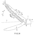
- FIG. 17 is a view showing still another example of the treatment of the grasp object.
- the jaw 60 is brought into contact with the grasp object S over a total length of the jaw in the jaw axis direction to perform the treatment. Therefore, in a state where the grasp object S is in contact with the jaw 60 over the total length of the jaw in the jaw axis direction, the grasp object S is grasped between the distal treatment section 33 of the probe 31 and the jaw 60. Further, the grasp object S is cut and simultaneously coagulated by the frictional heat generated between the distal treatment section 33 and the grasp object S. When the high frequency current flows through the grasp object S between the distal treatment section 33 and the jaw conductive member 62, the coagulation properties of the grasp object S are promoted.
- the movement of the grasp object S along the jaw axis J is regulated by the first distance changing portion 72A and the second distance changing portion 72B. Therefore, in the state where the grasp object S is grasped between the distal treatment section 33 and the jaw 60, the grasp object S does not move along the jaw axis J, and the grasp object S can efficiently be treated.
- the movement of the grasp object S toward the distal direction is regulated by the first distal side distance changing portion 83A and the second distal side distance changing portion 83B. Consequently, the movement of the grasp object S along the jaw axis J can more effectively be prevented.
- the movement of the grasp object S toward the proximal direction is regulated by the first proximal side distance changing portion 87A and the second proximal side distance changing portion 87B. In consequence, the movement of the grasp object S along the jaw axis J can more effectively be prevented.
- each of the first continuous surface 67A and the second continuous surface 67B is formed into a shape that does not regulate the movement of the grasp object along the jaw axis J in the state where the grasp object is interposed between the jaw 60 opened relative to the distal treatment section 33 and the distal treatment section 33.
- the first distance changing portion 72A and the second distance changing portion 72B that are the movement regulating portions are disposed in such positions that they do not come in contact with the grasp object in the state where the grasp object is interposed between the jaw 60 opened relative to the distal treatment section 33 and the distal treatment section 33.
- the grasp object in the state where the grasp object is interposed between the jaw 60 opened relative to the distal treatment section 33 and the distal treatment section 33, the grasp object can effectively be prevented from being hitched on the jaw 60. Additionally, in the state where the grasp object is grasped between the distal treatment section 33 and the jaw 60, the movement of the grasp object along the jaw axis J can be regulated by the first distance changing portion 72A and the second distance changing portion 72B.
- the first continuous surface 67A is the curved surface having the curved line shape with the large bending radius R1 in the cross section perpendicular to the first jaw width direction and the second jaw width direction
- the second continuous surface 67B is the curved surface having the curved line shape with the large bending radius R2 in the cross section perpendicular to the first jaw width direction and the second jaw width direction
- a first continuous surface 67A may be a flat surface having a linear shape in a cross section perpendicular to a first jaw width direction and a second jaw width direction.
- a second continuous surface 67B may be a flat surface having a straight line shape in the cross section perpendicular to the first jaw width direction and the second jaw width direction.
- FIG. 18 is a view showing the first continuous surface 67A of the present modification in the cross section perpendicular to the first jaw width direction and the second jaw width direction.
- each of the first continuous surface 67A and the second continuous surface 67B is one continuous surface, and hence in each of the first continuous surface 67A and the second continuous surface 67B, no narrowing sharp portion is formed.
- Each of the first continuous surface 67A and the second continuous surface 67B is formed into such a shape as described above, and hence in a state where a grasp object is interposed between a jaw 60 opened relative to a distal treatment section 33 and the distal treatment section 33, a movement of the grasp object along a jaw axis J is not regulated by the first continuous surface 67A and the second continuous surface 67B.
- the first continuous surface 67A is shaped in the form of one surface that forms the first-jaw-width-direction-side edge of the first non-contact portion 66A and is continuous along the jaw axis J.
- the second continuous surface 67B is shaped in the form of one surface that forms the second-jaw-width-direction-side edge of the second non-contact portion 66B and is continuous with the jaw axis J.
- each of the first continuous surface 67A and the second continuous surface 67B is formed into a shape that does not regulate the movement of the grasp object along the jaw axis J in the state where the grasp object is interposed between the jaw 60 opened relative to the distal treatment section 33 and the distal treatment section 33.
- each of the first distance changing portion 72A and the second distance changing portion 72B is provided as the movement regulating portion, but the present invention is not limited to this embodiment.
- a first distance changing portion 72A may only be provided.
- a second distance changing portion 72B is not provided in a second wall surface portion 71B of a second non-contact portion 66B.
- a movement of the grasp object along a jaw axis J is regulated by the first distance changing portion 72A.
- At least one of the first distance changing portion 72A and the second distance changing portion 72B may be provided. Consequently, in the state where the grasp object is grasped between the jaw 60 closed relative to the distal treatment section 33 and the distal treatment section 33, the movement of the grasp object along the jaw axis J is regulated.
- first distal side distance changing portion 83A and the second distal side distance changing portion 83B may be provided as a distal side distance changing portion. Consequently, in the state where the grasp object is grasped between the jaw 60 closed relative to the distal treatment section 33 and the distal treatment section 33, the movement of the grasp object along the jaw axis J is regulated by the entire width insulating portion 81.
- at least one of the first proximal side distance changing portion 87A and the second proximal side distance changing portion 87B may be provided. Consequently, in the state where the grasp object is grasped between the jaw 60 closed relative to the distal treatment section 33 and the distal treatment section 33, the movement of the grasp object along the jaw axis J is regulated by the proximal portion of the jaw 60.
- each of the first concave portions 75A on the first jaw width direction side is formed in a narrowing manner to be sharp in the first distance changing portion 72A
- the end of each of the second concave portions 75B on the second jaw width direction side is formed in a narrowing manner to be sharp in the second distance changing portion 72B
- each of first concave portions 75A and second concave portions 75B may be shaped in the form of a curved surface.
- first distance changing portion 72A and a second distance changing portion 72B are formed into such a shape to partially come in contact with the grasp object in the state where the grasp object is grasped between the jaw 60 closed relative to the distal treatment section 33 and the distal treatment section 33.
- first distance changing portion 72A and the second distance changing portion 72B are formed in a convex-and-concave manner.
- a first distance changing portion 91A may be provided in a first wall surface portion 71A facing toward a second jaw width direction (a direction of an arrow B2 of FIG. 21 ) in a first non-contact portion 66A
- a second distance changing portion 91B may be provided in a second wall surface portion 71B facing toward a first jaw width direction (a direction of an arrow B1 of FIG. 21 ) in a second non-contact portion 66B.
- first distance changing portion 91A similarly to a first distance changing portion 72A, a distance from a jaw axis J in the first jaw width direction changes along the jaw axis J.
- second distance changing portion 91B similarly to a second distance changing portion 72B, the distance from the jaw axis J in the second jaw width direction changes along the jaw axis J.
- the first distance changing portion 91A includes a first reference surface 93A positioned at a first reference distance L'1 from the jaw axis J in the first jaw width direction.
- the first distance changing portion 91A includes first convex portions 95A projecting from the first reference surface 93A toward the second jaw width direction.
- the distance from the jaw axis J in the first jaw width direction is smaller than the first reference distance L'1.
- An end of each of the first convex portions 95A on a second jaw width direction side is formed in a narrowing manner to be sharp.
- the first distance changing portion 91A is formed in a convex-and-concave manner by the first reference surface 93A and the first convex portions 95A.
- the first distance changing portion 91A that is a movement regulating portion, a movement of a grasp object along the jaw axis J is regulated in a state where the grasp object is grasped between a jaw 60 closed relative to a distal treatment section 33 and the distal treatment section 33.
- the first distance changing portion 91A is formed into such a shape to partially come in contact with a grasp object S in the state where the grasp object S is grasped between the jaw 60 closed relative to the distal treatment section 33 and the distal treatment section 33.
- the second distance changing portion 91B includes a second reference surface 93B positioned at a second reference distance L'2 from the jaw axis J in the second jaw width direction.
- the second distance changing portion 91B includes second convex portions 95B projecting from the second reference surface 93B toward the first jaw width direction.
- the distance from the jaw axis J in the second jaw width direction is smaller than the second reference distance L'2.
- An end of each of the second convex portions 95B on a first jaw width direction side is formed in a narrowing manner to be sharp.
- the second distance changing portion 91B is formed in a convex-and-concave manner by the second reference surface 93B and the second convex portions 95B.
- the second distance changing portion 91B that is a movement regulating portion, the movement of the grasp object along the jaw axis J is regulated in the state where the grasp object is grasped between the jaw 60 closed relative to the distal treatment section 33 and the distal treatment section 33.
- the second distance changing portion 91B is formed into such a shape to partially come in contact with the grasp object S in the state where the grasp object S is grasped between the jaw 60 closed relative to the distal treatment section 33 and the distal treatment section 33.
- the first distance changing portion 91A is positioned in the first wall surface portion 71A that is located on the second jaw width direction side with respect to a first continuous surface 67A to face toward the second jaw width direction. Consequently, similarly to the first embodiment, in a state where the grasp object is interposed between the jaw 60 opened relative to the distal treatment section 33 and the distal treatment section 33, the grasp object does not come in contact with the first distance changing portion 91A (the first wall surface portion 71A).
- the second distance changing portion 91B is positioned in the second wall surface portion 71B that is located on the first jaw width direction side with respect to a second continuous surface 67B to face toward the first jaw width direction.
- the grasp object does not come in contact with the second distance changing portion 91B (the second wall surface portion 71B) in the state where the grasp object is interposed between the jaw 60 opened relative to the distal treatment section 33 and the distal treatment section 33.
- the first distance changing portion 91A and the second distance changing portion 91B are provided as the movement regulating portions, but at least one of the first distance changing portion 91A and the second distance changing portion 91B may be provided.
- the movement of the grasp object along the jaw axis J is regulated in the state where the grasp object is grasped between the jaw 60 closed relative to the distal treatment section 33 and the distal treatment section 33.
- the movement regulating portions are disposed in the first wall surface portion 71A facing in the second jaw width direction and the second wall surface portion 71B facing in the first jaw width direction, but the present invention is not limited to this embodiment.
- a first wall surface portion 101A facing toward a jaw closing direction (a direction of an arrow A1 of FIG. 22 ) may be provided in a first non-contact portion 66A, and a second wall surface portion 101B facing toward the jaw closing direction may be provided in a second non-contact portion 66B.
- the first wall surface portion 101A is located on a second jaw width direction (a direction of an arrow B2 of FIG. 22 ) side with respect to a first continuous surface 67A
- the second wall surface portion 101B is located on a first jaw width direction (a direction of an arrow B1 of FIG. 22 ) side with respect to a second continuous surface 67B.
- a first distance changing portion 102A is provided to be located on a jaw opening direction (a direction of an arrow A2 of FIG. 22 ) side with respect to the first continuous surface 67A.
- a distance from the first continuous surface 67A in the jaw opening direction changes along a jaw axis J.
- the first distance changing portion 102A includes a first reference surface 103A positioned at a first reference distance H1 from the first continuous surface 67A in the jaw opening direction.
- the first distance changing portion 102A includes first concave portions 105A concaved from the first reference surface 103A toward the jaw opening direction.
- a distance of each of the first concave portions 105A from the first continuous surface 67A in the jaw opening direction is larger than the first reference distance H1.
- An end of each of the first concave portions 105A on the jaw opening direction side is formed in a narrowing manner to be sharp.
- the first distance changing portion 102A is formed in a convex-and-concave manner by the first reference surface 103A and the first concave portions 105A.
- the first distance changing portion 102A Due to the abovementioned configuration, in the first distance changing portion 102A, a movement of a grasp object along the jaw axis J is regulated in a state where the grasp object is grasped between a jaw 60 closed relative to a distal treatment section 33 and the distal treatment section 33. That is, the first distance changing portion 102A becomes a movement regulating portion.
- the first distance changing portion 102A is formed into such a shape to partially come in contact with the grasp object in the state where the grasp object is grasped between the jaw 60 closed relative to the distal treatment section 33 and the distal treatment section 33.
- the first distance changing portion 102A is positioned in the first wall surface portion 101A that is located on the second jaw width direction side with respect to the first continuous surface 67A to face toward the jaw closing direction, and is located on the jaw opening direction side with respect to the first continuous surface 67A. Consequently, the grasp object does not come in contact with the first distance changing portion 102A in a state where the grasp object is interposed between the jaw 60 opened relative to the distal treatment section 33 and the distal treatment section 33.
- a second distance changing portion 102B is provided to be positioned on the jaw opening direction side with respect to the second continuous surface 67B.
- a distance from the second continuous surface 67B in the jaw opening direction changes along the jaw axis J.
- the second distance changing portion 102B includes a second reference surface 103B positioned at a second reference distance H2 from the second continuous surface 67B in the jaw opening direction.
- the second distance changing portion 102B includes second concave portions 105B concaved from the second reference surface 103B toward the jaw opening direction. A distance of each of the second concave portions 105B from the second continuous surface 67B in the jaw opening direction is larger than the second reference distance H2.
- each of the second concave portions 105B on the jaw opening direction side is formed in a narrowing manner to be sharp.
- the second distance changing portion 102B is formed in a convex-and-concave manner by the second reference surface 103B and the second concave portions 105B.
- the movement of the grasp object along the jaw axis J is regulated in the state where the grasp object is grasped between the jaw 60 closed relative to the distal treatment section 33 and the distal treatment section 33. That is, the second distance changing portion 102B becomes a movement regulating portion.
- the second distance changing portion 102B is formed into such a shape to partially come in contact with the grasp object in the state where the grasp object is grasped between the jaw 60 closed relative to the distal treatment section 33 and the distal treatment section 33.
- the second distance changing portion 102B is positioned in the second wall surface portion 101B that is located on the first jaw width direction side with respect to the second continuous surface 67B to face in the jaw closing direction, and is positioned on the jaw opening direction side with respect to the second continuous surface 67B. Consequently, the grasp object does not come in contact with the second distance changing portion 102B in the state where the grasp object is interposed between the jaw 60 opened relative to the distal treatment section 33 and the distal treatment section 33.
- the first distance changing portion 102A and the second distance changing portion 102B are provided as the movement regulating portions, but at least one of the first distance changing portion 102A and the second distance changing portion 102B may be provided. Consequently, the movement of the grasp object along the jaw axis J is regulated in the state where the grasp object is grasped between the jaw 60 closed relative to the distal treatment section 33 and the distal treatment section 33.
- a first distance changing portion 111A may be provided in a first wall surface portion 101A facing toward a jaw closing direction (a direction of an arrow A1 of FIG. 23 ) in a first non-contact portion 66A
- a second distance changing portion 111B may be provided in a second wall surface portion 101B facing toward the jaw closing direction in a second non-contact portion 66B.
- the first distance changing portion 111A is disposed on a jaw opening direction (a direction of an arrow A2 of FIG. 23 ) side with respect to a first continuous surface 67A, and a distance from the first continuous surface 67A in the jaw opening direction changes along a jaw axis J.
- the second distance changing portion 111B is disposed on the jaw opening direction side with respect to a second continuous surface 67B, and a distance from the second continuous surface 67B in the jaw opening direction changes along the jaw axis J.
- the first distance changing portion 111A includes a first reference surface 113A positioned at a first reference distance H'1 from the first continuous surface 67A in the jaw opening direction.
- the first distance changing portion 111A incudes first convex portions 115A projecting from the first reference surface 113A toward the jaw closing direction.
- a distance of each of the first convex portions 115A from the first continuous surface 67A in the jaw opening direction is smaller than the first reference distance H'1.
- An end of each of the first convex portions 115A on the jaw closing direction side is formed in a narrowing manner to be sharp.
- the first distance changing portion 111A is formed in a convex-and-concave manner by the first reference surface 113A and the first convex portions 115A.
- the first distance changing portion 111A that is a movement regulating portion, a movement of a grasp object along the jaw axis J is regulated in a state where the grasp object is grasped between a jaw 60 closed relative to a distal treatment section 33 and the distal treatment section 33.
- the first distance changing portion 111A is formed into such a shape to partially come in contact with a grasp object S in the state where the grasp object S is grasped between the jaw 60 closed relative to the distal treatment section 33 and the distal treatment section 33.
- the second distance changing portion 111B includes a second reference surface 113B positioned at a second reference distance H'2 from the second continuous surface 67B in the jaw opening direction.
- the second distance changing portion 111B includes second convex portions 115B projecting from the second reference surface 113B toward the jaw closing direction.
- a distance of each of the second convex portions 115B from the second continuous surface 67B in the jaw opening direction is smaller than the second reference distance H'2.
- a jaw-closing-direction-side end of each of the second convex portions 115B is formed in a narrowing manner to be sharp.
- the second distance changing portion 111B is formed in a convex-and-concave manner by the second reference surface 113B and the second convex portions 115B. Due to the abovementioned configuration, in the second distance changing portion 111B that is a movement regulating portion, the movement of the grasp object along the jaw axis J is regulated in the state where the grasp object is grasped between the jaw 60 closed relative to the distal treatment section 33 and the distal treatment section 33. In addition, the second distance changing portion 111B is formed into such a shape to partially come in contact with the grasp object S in the state where the grasp object S is grasped between the jaw 60 closed relative to the distal treatment section 33 and the distal treatment section 33.
- the first distance changing portion 111A is positioned in the first wall surface portion 101A that is disposed on a second jaw width direction side with respect to the first continuous surface 67A to face toward the jaw closing direction, and is positioned on the jaw opening direction side with respect to the first continuous surface 67A. In consequence, the grasp object does not come in contact with the first distance changing portion 111A in a state where the grasp object is interposed between the jaw 60 opened relative to the distal treatment section 33 and the distal treatment section 33.
- the second distance changing portion 111B is positioned in the second wall surface portion 101B that is located on a first jaw width direction side with respect to the second continuous surface 67B to face in the jaw closing direction, and is positioned on the jaw opening direction side with regard to the second continuous surface 67B.
- the grasp object does not come in contact with the second distance changing portion 111B in the state where the grasp object is interposed between the jaw 60 opened relative to the distal treatment section 33 and the distal treatment section 33.
- the first distance changing portion 111A and the second distance changing portion 111B are provided as the movement regulating portions, but at least one of the first distance changing portion 111A and the second distance changing portion 111B may be provided.
- the movement of the grasp object along the jaw axis J is regulated in the state where the grasp object is grasped between the jaw 60 closed relative to the distal treatment section 33 and the distal treatment section 33.
- the movement regulating portion (72A, 72B; 72A; 91A, 91B; 102A, 102B; 111A, 111B) is provided in at least one of a region of the first non-contact portion 66A which is located on the second jaw width direction side with respect to the first continuous surface 67A and a region of the second non-contact portion 66B which is located on the first jaw width direction side with respect to the second continuous surface 67B.
- the movement of the grasp object along the jaw axis J is regulated by the movement regulating portion (72A, 72B; 72A; 91A, 91B; 102A, 102B; 111A, 111B).
- the movement regulating portion 72A, 72B; 72A; 91A, 91B; 102A, 102B; 111A, 111B
- the movement regulating portion is positioned at such a position that does not come in contact with the grasp object in the state where the grasp object is interposed between the jaw 60 opened relative to the distal treatment section 33 and the distal treatment section 33.
- the movement of the grasp object along the jaw axis J can be regulated in the state where the grasp object is grasped between the distal treatment section 33 and the jaw 60.
- the grasp object can effectively be prevented from being hitched on the jaw 60 in the state where the grasp object is interposed between the jaw 60 opened relative to the distal treatment section 33 and the distal treatment section 33.
- the movement regulating portion (72A, 72B; 72A; 91A, 91B; 102A, 102B; 111A, 111B) is formed into such a shape to partially come in contact with the grasp object in the state where the grasp object is grasped between the jaw 60 closed relative to the distal treatment section 33 and the distal treatment section 33.
- the contact area between each of the first non-contact portion 66A and the second non-contact portion 66B that are the jaw electrode portions and the biological tissue decreases.
- the current density of the high frequency current flowing through the grasp object S heightens. In consequence, the coagulation properties of the grasp object S by the high frequency current can improve, and the treatment efficiency of the grasp object by use of the high frequency current can improve.
- a first grasping member 131 and a second grasping member 132 are attached to a distal portion of a sheath 40 so that the members can turn about a coupling screw 55 (a pivoting axis P).
- the first grasping member 131 and the second grasping member 132 pivot, the first grasping member 131 and the second grasping member 132 perform an opening motion or a closing motion relative to each other.
- the first grasping member 131 and the second grasping member 132 close relative to each other in a state where a treatment object is interposed between the first grasping member 131 and the second grasping member 132, the treatment object is grasped between the first grasping member 131 and the second grasping member 132.
- a conductive portion (not shown) is provided in each of the first grasping member 131 and the second grasping member 132 in the state where the treatment object is grasped.
- the high frequency current flows through the treatment object grasped between the first grasping member 131 and the second grasping member 132, and a bipolar treatment is performed.
- a monopolar treatment is also performed.
- the high frequency current does not have to be transmitted to the first grasping member 131 and the second grasping member 132.
- a configuration similar to the jaw 60 of the first embodiment is applied to the first grasping member 131. That is, in the first grasping member 131, an abutment portion 65 that can abut on the second grasping member 132 is disposed in the same manner as in the jaw 60 of the first embodiment. Further, directions perpendicular to a member axis J1 of the first grasping member 131 and perpendicular to opening and closing directions (a direction of an arrow A1 and a direction of an arrow A2 in FIG. 24 ) of the first grasping member 131 are a first width direction (a direction of an arrow B1 of FIG. 24 ) and a second width direction (a direction of an arrow B2 of FIG. 24 ).
- a first non-contact portion 66A is provided on a first width direction side with respect to the abutment portion 65, and a second non-contact portion 66B is provided on a second width direction side with respect to the abutment portion 65.
- the first non-contact portion 66A and the second non-contact portion 66B are disposed to face the second grasping member 132, and have a space between them and the second grasping member 132 in a state where the abutment portion 65 abuts on the second grasping member 132.
- an edge of the first non-contact portion 66A on a first width direction side is formed by the first continuous surface 67A
- an edge of the second non-contact portion 66B is formed by a second continuous surface 67B.
- a first wall surface portion 71A facing toward the second width direction is disposed
- a second wall surface portion 71B facing toward the first width direction is disposed.
- a first distance changing portion 72A is formed as a movement regulating portion in which a distance from the member axis J1 in the first width direction changes along the member axis J1.
- a second distance changing portion 72B is formed in which a distance from the member axis J1 in the second width direction changes along the member axis J1.
- the configuration of the jaw 60 of the first embodiment is applied to the first grasping member 131, but the configuration of the jaw 60 of the first embodiment may be applied to the second grasping member 132.
- the configuration of the jaw 60 of the first embodiment may be applied to both of the first grasping member 131 and the second grasping member 132.
- the configuration of the jaw 60 of one of the first modification to the sixth modification may be applied to the first grasping member 131, and the configuration of the jaw 60 of one of the first modification to the sixth modification may be applied to the second grasping member 132.
- the configuration of the jaw 60 of one of the first modification to the sixth modification may be applied to both of the first grasping member 131 and the second grasping member 132.
- a probe 31 is not provided, and in a sheath 40, a sheath projecting portion 133 is disposed to be extended from a coupling screw 55 (a turning axis P) toward a distal direction.
- a jaw 60 is attached to the sheath 40 so that the jaw can turn around the coupling screw 55 (the pivoting axis P).
- the jaw 60 pivots, and hence the jaw 60 performs an opening motion or a closing motion relative to the sheath projecting portion 133.
- the jaw 60 When the jaw 60 is closed relative to the sheath projecting portion 133 in a state where a grasp object (a treatment object) is interposed between the jaw 60 and the sheath projecting portion 133, the grasp object is grasped between the jaw 60 and the sheath projecting portion 133.
- energy such as ultrasonic vibration or high frequency current is not transmitted to the sheath projecting portion 133.
- the high frequency current is not transmitted to the jaw 60.
- the high frequency current may be transmitted to the jaw 60 and the sheath projecting portion 133.
- a configuration similar to the jaw 60 of the first embodiment is applied to the jaw 60. That is, in the jaw 60, an abutment portion 65 that can abut on the sheath projecting portion 133 is provided in the same manner as in the jaw 60 of the first embodiment. Further, directions that are perpendicular to a jaw axis J of the jaw 60 and perpendicular to opening and closing directions of the jaw 60 (a direction of an arrow A1 and a direction of an arrow A2 in FIG. 25 ) are defined as a first width direction (a direction of an arrow B1 of FIG. 25 ) and a second width direction (a direction of an arrow B2 of FIG. 25 ).
- a first non-contact portion 66A is provided on a first width direction side with regard to the abutment portion 65, and a second non-contact portion 66B is disposed on a second width direction side with respect to the abutment portion 65.
- the first non-contact portion 66A and the second non-contact portion 66B are provided to face the sheath projecting portion 133, and have a space between them and the sheath projecting portion 133 in a state where the abutment portion 65 abuts on the sheath projecting portion 133.
- a first-width-direction-side edge of the first non-contact portion 66A is formed by a first continuous surface 67A
- a second-width-direction-side edge of the second non-contact portion 66B is formed by a second continuous surface 67B.
- a first wall surface portion 71A facing in the second width direction is disposed
- a second wall surface portion 71B facing in the first width direction is disposed.
- a first distance changing portion 72A is formed as a movement regulating portion in which a distance from the jaw axis J in the first width direction changes along the jaw axis J.
- a second distance changing portion 72B is formed in which a distance from the jaw axis J in the second width direction changes along the jaw axis J.
- the configuration of the jaw 60 of the first embodiment is applied to the jaw 60, but the configuration of the jaw 60 of one of the first modification to the sixth modification may be applied to the jaw 60.
- a probe 31 in which an ultrasonic vibration is transmitted up to a distal treatment section 33, and a jaw 60 that is openable and closable relative to the distal treatment section 33 there are disposed a probe 31 in which an ultrasonic vibration is transmitted up to a distal treatment section 33, and a jaw 60 that is openable and closable relative to the distal treatment section 33.
- the probe 31 includes a probe side facing portion 121 disposed to face the jaw 60.
- inclined surfaces 122 inclining relative to a longitudinal axis C are disposed. That is, the inclined surfaces 122 that are not parallel to the longitudinal axis C are disposed. Consequently, when the ultrasonic vibration is transmitted to the distal treatment section 33 in a state where a physiological salt solution is fed to the vicinity of the probe side facing portion 121, cavitation occurs on the inclined surfaces 122.
- the liver cell When a blood vessel in a liver cell or the like is treated, the liver cell is grasped as a grasp object between the distal treatment section 33 and the jaw 60. When the cavitation is caused on the inclined surfaces 122 in this state, the liver cell having low elasticity is shattered and emulsified. When the liver cell is emulsified, the blood vessel in the liver cell is exposed. It is to be noted that the blood vessel having high elasticity is not shattered by the cavitation.
- a perpendicular surface 123 perpendicular to a longitudinal axis C may be disposed in a probe side facing portion 121.
- an ultrasonic vibration is transmitted to a distal treatment section 33 in a state where a physiological salt solution or the like is fed to the vicinity of the probe side facing portion 121, and hence, cavitation occurs on the perpendicular surface 123. That is, in the probe side facing portion 121, there may be disposed at least one of the inclined surface 122 and the perpendicular surface 123 which are not parallel to the longitudinal axis C.
- a probe 31 in which an ultrasonic vibration is transmitted up to a distal treatment section 33, and a jaw 60 openable and closable relative to the distal treatment section 33.
- the jaw 60 includes a jaw side facing portion 125 facing the distal treatment section 33.
- a region of an outer surface of the jaw 60 except the jaw side facing portion 125 is a non-facing portion 126.
- the non-facing portion 126 of the jaw 60 is covered with a heat insulating cover 127.
- the heat insulating cover 127 is made of a material having higher heat insulating properties than materials of a jaw main body 61, a jaw conductive member 62 and a jaw insulating member 63. In addition, the heat insulating cover 127 can be removed from the jaw 60.
- a region of a non-facing portion 126 on a first jaw width direction (a direction of an arrow B1 of FIG. 29 ) side is covered with a heat insulating cover 127. Therefore, a region of the non-facing portion 126 on a second jaw width direction (a direction of an arrow B2 of FIG. 29 ) side is not covered with the heat insulating cover 127.
- the second jaw width direction coincides with a direction in which a jaw 60 and a distal treatment section 33 are moved in a treatment. Consequently, a biological tissue or the like on the second jaw width direction side with respect to the jaw 60 will be grasped as a grasp object by moving the jaw 60 from a current position.
- a heat insulating cover 127 is extended up to a region located on a jaw closing direction (a direction of an arrow A1 of FIG. 30 ) side with respect to the distal treatment section 33 of a probe 31. Consequently, a region of an outer surface of the distal treatment section 33 on a first jaw width direction side is covered with the heat insulating cover 127.
- energy such as an ultrasonic vibration and a high frequency current are used
- heat generated by the energy raises a temperature of the distal treatment section 33 in addition to the jaw 60.
- the outer surface of the distal treatment section 33 is covered with the heat insulating cover 127, and hence, a biological tissue or the like other than the grasp object does not come in contact with the distal treatment section 33 having the high temperature. In consequence, impairment of the biological tissue or the like other than the grasp object due to the heat is further effectively prevented.
- a grasping unit which is extended along a jaw axis, which is openable and closable relative to a distal treatment section provided in a probe in jaw opening and closing directions perpendicular to the jaw axis, and which is capable of grasping a grasp object between the grasping unit and the distal treatment section in a state where the grasping unit is closed relative to the distal treatment section, the grasping unit comprising:
- a grasping treatment device comprising:
Landscapes
- Health & Medical Sciences (AREA)
- Surgery (AREA)
- Engineering & Computer Science (AREA)
- Life Sciences & Earth Sciences (AREA)
- Biomedical Technology (AREA)
- Public Health (AREA)
- Nuclear Medicine, Radiotherapy & Molecular Imaging (AREA)
- Veterinary Medicine (AREA)
- General Health & Medical Sciences (AREA)
- Heart & Thoracic Surgery (AREA)
- Medical Informatics (AREA)
- Molecular Biology (AREA)
- Animal Behavior & Ethology (AREA)
- Physics & Mathematics (AREA)
- Otolaryngology (AREA)
- Plasma & Fusion (AREA)
- Surgical Instruments (AREA)
- Dentistry (AREA)
- Mechanical Engineering (AREA)
Abstract
Description
- The present invention relates to a grasping treatment device which includes a probe having a distal treatment section disposed in a distal portion thereof, and a jaw that is a grasping unit openable and closable relative to the distal treatment section, and which is capable of grasping a grasp object between the distal treatment section and the jaw.
- In
Patent Literature 1, there is disclosed a grasping treatment device including a probe which is extended along a longitudinal axis and in a distal end of which a distal treatment section is disposed, and a jaw which is a grasping unit openable and closable relative to the distal treatment section. In the grasping treatment device, it is possible to grasp a grasp object such as a biological tissue between the distal treatment section and the jaw, and in a state where the grasp target is grasped between the distal treatment section and the jaw, a treatment of the grasp object is performed. The jaw is extended along a jaw axis, and includes an abutment portion that can abut on the distal treatment section in a state where the jaw is closed relative to the distal treatment section. Here, directions that are perpendicular to the jaw axis and perpendicular to a jaw opening-or-closing direction are defined as a first jaw width direction and a second jaw width direction. The jaw includes a first non-contact portion which is provided to face the distal treatment section on a first jaw width direction side with respect to the abutment portion, and which has a space between it and the distal treatment section in a state where the abutment portion abuts on the distal treatment section. In addition, the jaw includes a second non-contact portion which is disposed to face the distal treatment section on a second jaw width direction side with respect to the abutment portion, and which has a space between it and the distal treatment section in the state where the abutment portion abuts on the distal treatment section. In the first non-contact portion, there is provided a first distance changing portion which forms an edge of the first non-contact portion on the first jaw width direction side, and in which a distance from the distal treatment section in a jaw opening direction changes along the jaw axis. Additionally, in the second non-contact portion, there is provided a second distance changing portion which forms an edge of the second non-contact portion on the second jaw width direction side, and in which a distance from the distal treatment section in the jaw opening direction changes along the jaw axis. In the state where the grasp object is grasped between the distal treatment section and the jaw, a movement of the grasp object along the jaw axis (the longitudinal axis) is regulated by the first distance changing portion and the second distance changing portion. - Patent Literature 1: Jpn. Pat. Appln. KOKAI Publication No.
2009-160404 - In the grasping treatment device including the probe and the jaw as in
Patent Literature 1, it is necessary to insert, from a distal direction side, the grasp object to be grasped between the jaw opened relative to the distal treatment section and the probe. In the grasping treatment device ofPatent Literature 1, the first distance changing portion is provided in the first non-contact portion facing the distal treatment section, and the edge of the first non-contact portion on the first jaw width direction side is formed by the first distance changing portion. Consequently, in a state where the grasp object is interposed between the jaw opened relative to the distal treatment section and the distal treatment section, the grasp object is easily hitched on the first distance changing portion. Additionally, in the grasping treatment device ofPatent Literature 1, the second distance changing portion is disposed in the second non-contact portion facing the distal treatment section, and the edge of the second non-contact portion on the second jaw width direction side is formed by the second distance changing portion. Consequently, in the state where the grasp object is interposed between the jaw opened relative to the distal treatment section and the distal treatment section, the grasp object is easily hitched on the second distance changing portion. Thus, the grasp object is hitched on the first distance changing portion or the second distance changing portion, and hence, treatment performance of the grasp object disadvantageously deteriorates. - The present invention has been developed in view of the above problems, and an object thereof is to provide a grasping treatment device in which a movement of a grasp object along a jaw axis is regulated in a state where the grasp object is grasped between a distal treatment section and a jaw, and in which the grasp object is effectively prevented from being hitched on the jaw in a state where the grasp object is interposed between the jaw opened relative to the distal treatment section and the distal treatment section.
- To solve above mentioned problems, according to one aspect of the invention, a grasping treatment device includes: a probe which is extended along a longitudinal axis and which includes a distal treatment section in a distal portion thereof; a jaw which is extended along a jaw axis, and which is openable and closable relative to the distal treatment section of the probe in jaw opening and closing directions perpendicular to the jaw axis, the jaw being configured to grasp a grasp object between the jaw and the distal treatment section in a state where the jaw is closed relative to the distal treatment section; an abutment portion which is provided in the jaw, and which is configured to abut on the distal treatment section in the state where the jaw is closed relative to the distal treatment section; a first non-contact portion which is provided on a first jaw width direction side with respect to the abutment portion in the jaw to face the distal treatment section, and which has a space between the first non-contact portion and the distal treatment section in a state where the abutment portion abuts on the distal treatment section, directions that are perpendicular to the jaw axis and perpendicular to the jaw opening and closing directions being defined as a first jaw width direction and a second jaw width direction; a second non-contact portion which is provided on a second jaw width direction side with respect to the abutment portion in the jaw to face the distal treatment section, and which has a space between the second non-contact portion and the distal treatment section in the state where the abutment portion abuts on the distal treatment section; a first continuous surface which forms an edge of the first non-contact portion on the first jaw width direction side, and which is shaped in a form of one surface continuous along the jaw axis, the first continuous surface being formed into a shape that does not regulate movement of the grasp object along the jaw axis in a state where the grasp object is interposed between the jaw opened relative to the distal treatment section and the distal treatment section; a second continuous surface which forms an edge of the second non-contact portion on the second jaw width direction side, and which is shaped in a form of one surface continuous along the jaw axis, the second continuous surface being formed into a shape that does not regulate the movement of the grasp object along the jaw axis in the state where the grasp object is interposed between the jaw opened relative to the distal treatment section and the distal treatment section; and a movement regulating portion which is provided in at least one of a region of the first non-contact portion located on the second jaw width direction side with respect to the first continuous surface and a region of the second non-contact portion located on the first jaw width direction side with respect to the second continuous surface, and which is configured to regulate the movement of the grasp object along the jaw axis in a state where the grasp object is grasped between the jaw closed relative to the distal treatment section and the distal treatment section, the movement regulating portion being positioned in a position that does not come in contact with the grasp object in the state where the grasp object is interposed between the jaw opened relative to the distal treatment section and the distal treatment section.
- According to the present invention, a grasping treatment device, in which a movement of a grasp object along a jaw axis is regulated in a state where the grasp object is grasped between a distal treatment section and a jaw and in which the grasp object is effectively prevented from being hitched on the jaw in a state where the grasp object is interposed between the jaw opened relative to the distal treatment section and the distal treatment section, can be provided.
-
-
FIG. 1 is a schematic view showing a configuration of a grasping treatment system in which a grasping treatment device according to a first embodiment is used; -
FIG. 2 is a cross-sectional view schematically showing a configuration of a vibrator unit according to the first embodiment; -
FIG. 3 is a cross-sectional view schematically showing an inner configuration of a cylindrical case portion of a holding unit according to the first embodiment; -
FIG. 4 is a schematic view showing a configuration of a distal portion of the grasping treatment device according to the first embodiment; -
FIG. 5 is a perspective view schematically showing the configuration of the distal portion of the grasping treatment device according to the first embodiment; -
FIG. 6 is a perspective view schematically showing a configuration of a distal portion of a sheath and a jaw according to the first embodiment; -
FIG. 7 is a perspective view schematically showing a configuration of a jaw conductive member and a jaw insulating member of the jaw according to the first embodiment; -
FIG. 8 is a cross-sectional view schematically showing the jaw and a distal treatment section according to the first embodiment in a given cross section perpendicular to a jaw axis and a longitudinal axis; -
FIG. 9 is a cross-sectional view schematically showing the jaw and the distal treatment section according to the first embodiment in a given cross section that is perpendicular to the jaw axis and the longitudinal axis and is different from that ofFIG. 8 ; -
FIG. 10 is a cross-sectional view schematically showing the jaw and the distal treatment section according to the first embodiment in a given cross section that is perpendicular to the jaw axis and the longitudinal axis and is different from those ofFIG. 8 and FIG. 9 ; -
FIG. 11 is a cross-sectional view schematically showing the jaw and the distal treatment end according to the first embodiment in a given cross section that is perpendicular to the jaw axis and the longitudinal axis and is different from those ofFIG. 8 to FIG. 10 ; -
FIG. 12 is a cross-sectional view schematically showing a first continuous surface of the jaw according to the first embodiment in a cross section perpendicular to a first jaw width direction and a second jaw width direction; -
FIG. 13 is a perspective view schematically showing a configuration of a first non-contact portion and a second non-contact portion of the jaw according to the first embodiment; -
FIG. 14 is a cross-sectional view schematically showing a first distance changing portion in a state where a grasp object is grasped between the jaw and the distal treatment section according to the first embodiment, in a cross section perpendicular to a jaw opening-and-closing direction; -
FIG. 15 is a schematic view showing a certain example of a treatment of the grasp object by the grasping treatment device according to the first embodiment; -
FIG. 16 is a schematic view showing another example of the treatment of the grasp object by the grasping treatment device according to the first embodiment, different from the example ofFIG. 15 ; -
FIG. 17 is a schematic view showing still another example of the treatment of the grasp object by the grasping treatment device according to the first embodiment, different from the examples ofFIG. 15 and FIG. 16 ; -
FIG. 18 is a cross-sectional view schematically showing a first continuous surface of a jaw according to a first modification in a cross section perpendicular to a first jaw width direction and a second jaw width direction; -
FIG. 19 is a perspective view schematically showing a part of a jaw according to a second modification; -
FIG. 20 is a perspective view schematically showing a configuration of a first non-contact portion and a second non-contact portion of a jaw according to a third modification; -
FIG. 21 is a perspective view schematically showing a configuration of a first non-contact portion and a second non-contact portion of a jaw according to a fourth modification; -
FIG. 22 is a perspective view schematically showing a configuration of a first non-contact portion and a second non-contact portion of a jaw according to a fifth modification; -
FIG. 23 is a perspective view schematically showing a configuration of a first non-contact portion and a second non-contact portion of a jaw according to a sixth modification; -
FIG. 24 is a perspective view schematically showing a configuration of a distal portion of a grasping treatment device according to a seventh modification; -
FIG. 25 is a perspective view schematically showing a configuration of a distal portion of a grasping treatment device according to an eighth modification; -
FIG. 26 is a schematic view showing a configuration of a distal portion of a grasping treatment device according to a first reference example; -
FIG. 27 is a schematic view showing a configuration of a distal portion of a grasping treatment device according to a second reference example; -
FIG. 28 is a cross-sectional view schematically showing a jaw and a distal treatment section according to a third reference example in a given cross section perpendicular to a longitudinal axis; -
FIG. 29 is a cross-sectional view schematically showing a jaw and a distal treatment section according to a fourth reference example in a given cross section perpendicular to a longitudinal axis; and -
FIG. 30 is a cross-sectional view schematically showing a jaw and a distal treatment section according to a fifth reference example in a given cross section perpendicular to a longitudinal axis. - A first embodiment of the present invention will be described with reference to
FIG. 1 to FIG. 17 . -
FIG. 1 is a view showing a configuration of agrasping treatment system 1 in which agrasping treatment device 2 of the present embodiment is used. As shown inFIG. 1 , the grasping treatment device (a hand piece) 2 has a longitudinal axis C. Here, one of directions parallel to the longitudinal axis C is a distal direction (a direction of an arrow C1 ofFIG. 1 ), and an opposite direction to the distal direction is a proximal direction (a direction of an arrow C2 ofFIG. 1 ). Further, the distal direction and the proximal direction are defined as longitudinal axis directions. The graspingtreatment device 2 is an ultrasonic treatment device configured to perform a treatment of a grasp object such as a biological tissue by use of an ultrasonic vibration. In addition, the graspingtreatment device 2 is a high frequency treatment device (a bipolar treatment device) configured to perform the treatment of the grasp object by use of a high frequency current. - The grasping
treatment device 2 includes a holdingunit 3. The holdingunit 3 includes acylindrical case portion 5 extended along the longitudinal axis C, a fixed handle 6 formed integrally with thecylindrical case portion 5, and amovable handle 7 attached to thecylindrical case portion 5 to be turnable relative to the cylindrical case portion. When themovable handle 7 pivots around a position where the movable handle is attached to thecylindrical case portion 5, themovable handle 7 performs an opening-or-closing motion relative to the fixed handle 6. In addition, the holdingunit 3 includes arotary operation knob 8 attached to the distal direction side of thecylindrical case portion 5. Therotary operation knob 8 is rotatable relative to thecylindrical case member 5 around the longitudinal axis C. Additionally, in the fixed handle 6, there is disposed an energy operation input button 9 that is an energy operation input section. - The grasping
treatment device 2 includes avibrator unit 11. Thevibrator unit 11 includes avibrator case 12. Thevibrator case 12 is rotatable relative to thecylindrical case portion 5 around the longitudinal axis C, integrally with therotary operation knob 8. By inserting thevibrator case 12 from a proximal direction side into thecylindrical case portion 5, thevibrator case 12 is attached to the holdingunit 3. To thevibrator case 12, one end of acable 13 is connected. The graspingtreatment system 1 includes acontrol unit 15. The other end of thecable 13 is connected to thecontrol unit 15. Thecontrol unit 15 includes an ultrasoniccurrent supply section 16, a high frequencycurrent supply section 17, and anenergy control section 18. Here, thecontrol unit 15 is an energy generator including a CPU (Central Processing Unit), an ASIC (Application Specific Integrated Circuit) and the like. In addition, the ultrasoniccurrent supply section 16 and the high frequencycurrent supply section 17 are power sources disposed in, e.g., the energy generator, and theenergy control section 18 is formed from an electronic circuit (a control circuit) disposed in, e.g., the CPU, the ASIC or the like. -
FIG. 2 is a view showing a configuration of thevibrator unit 11. As shown inFIG. 2 , the vibrator unit includes anultrasonic vibrator 21 that is a vibration generating section provided in thevibrator case 12. Theultrasonic vibrator 21 includes a plurality of (four in the present embodiment)piezoelectric elements 22A to 22D configured to convert the current to the ultrasonic vibration. To theultrasonic vibrator 21, one end of each ofelectric wires electric wires cable 13, and the other ends of the respectiveelectric wires current supply section 16 of thecontrol unit 15. When the current is supplied to theultrasonic oscillator 21 from the ultrasoniccurrent supply section 16 via theelectric wires ultrasonic vibrator 21. - The
ultrasonic vibrator 21 is attached to acolumnar horn member 25. Thehorn member 25 includes a sectionalarea changing portion 27 in which a sectional area perpendicular to the longitudinal axis C changes. The ultrasonic vibration generated in theultrasonic vibrator 21 is transmitted to thehorn member 25, and in thehorn member 25, the ultrasonic vibration is transmitted from the proximal direction toward the distal direction. An amplitude of the ultrasonic vibration transmitted to thehorn member 25 is enlarged in the sectionalarea changing portion 27. Additionally, in a distal portion of thehorn member 25, aninternal thread portion 28 is provided. - The grasping
treatment device 2 includes acolumnar probe 31 extended from the inside of thecylindrical case portion 5 toward the distal direction along the longitudinal axis C. In a proximal portion of theprobe 31, anexternal thread portion 32 is disposed. By screwing theexternal thread portion 32 into theinternal thread portion 28, theprobe 31 is connected to a distal direction side of thehorn member 25. Theprobe 31 is connected to thehorn member 25 inside thecylindrical case member 5. Theultrasonic vibrator 21, thehorn member 25 and theprobe 31 are rotatable relative to thecylindrical case portion 5 around the longitudinal axis C, together with therotary operation knob 8. - In the state where the
probe 31 is connected to thehorn member 25, the ultrasonic vibration is transmitted from thehorn member 25 to theprobe 31. Further, in theprobe 31, the ultrasonic vibration is transmitted from the proximal direction toward the distal direction along the longitudinal axis C. At a distal portion of theprobe 31, adistal treatment section 33 is disposed. In theprobe 31, the ultrasonic vibration is transmitted to thedistal treatment section 33. It is to be noted that the distal end of theprobe 31 and a proximal end of thehorn member 25 become antinode positions of the ultrasonic vibration. In addition, the ultrasonic vibration is a longitudinal vibration in which a vibrating direction and a transmitting direction are parallel to the longitudinal axis C. - To the
horn member 25, one end of anelectric wire 35 is connected. Theelectric wire 35 is extended through the inside of thecable 13, and the other end of theelectric wire 35 is connected to the high frequencycurrent supply section 17 of thecontrol unit 15. Consequently, a probe side current path of the high frequency current to be supplied from the high frequencycurrent supply section 17 is formed from the high frequencycurrent supply section 17 through theelectric wire 35, thehorn member 25 and theprobe 31 to thedistal treatment section 33. When the high frequency current (high frequency energy) is supplied to thedistal treatment section 33 via the probe side current path, thedistal treatment section 33 functions as a probe electrode portion having a first potential E1. - The grasping
treatment device 2 includes asheath 40 extended along the longitudinal axis C. By inserting thesheath 40 from the distal direction side into therotary operation knob 8 and thecylindrical case portion 5, thesheath 40 is attached to the holdingunit 3. Inside thecylindrical case portion 5, thesheath 40 is attached to the distal direction side of thevibrator case 12. -
FIG. 3 is a view showing an internal configuration of thecylindrical case portion 5 of the holdingunit 3. As shown inFIG. 3 , thesheath 40 includes a connectioncylindrical portion 41 made of an insulating material, and a movablecylindrical portion 42 provided on an outer peripheral direction side with respect to the connectioncylindrical portion 41. The movablecylindrical portion 42 is made of a conductive material, and is movable relative to thevibrator case 12 and the connectioncylindrical portion 41 along the longitudinal axis C. In an outer peripheral portion of the movablecylindrical portion 42, aslider member 43 made of an insulating material is provided. Theslider member 43 is movable relative to the movablecylindrical portion 42 along the longitudinal axis C. Theslider member 43 is connected to the movablecylindrical portion 42 via anelastic member 45 such as a coil spring. In addition, themovable handle 7 is attached to theslider member 43. When themovable handle 7 is opened or closed relative to the fixed handle 6, a drive force is transmitted to theslider member 43, and theslider member 43 moves along the longitudinal axis C. Further, the drive force is transmitted from theslider member 43 to the movablecylindrical portion 42 via theelastic member 45, and the movablecylindrical portion 42 moves to thevibrator case 12 and the connectioncylindrical portion 41 along the longitudinal axis C. - As shown in
FIG. 2 and FIG. 3 , aconductive portion 47 is formed in thevibrator case 12. To theconductive portion 47, one end of anelectric wire 48 is connected. Theelectric wire 48 is extended through the inside of thecable 13, and the other end of theelectric wire 48 is connected to the high frequencycurrent supply section 17 of thecontrol unit 15. Further, in a state where thesheath 40 is connected to thevibrator case 12, the movablecylindrical portion 42 of thesheath 40 movably abuts on theconductive portion 47 of theoscillator case 12. Consequently, in the state where thesheath 40 is connected to thevibrator case 12, thevibrator case 12 is electrically connected to the movablecylindrical portion 42. In consequence, the high frequency current is supplied from the high frequencycurrent supply section 17 to the movablecylindrical portion 42 of thesheath 40 through theelectric wire 48 and theconductive portion 47 of thevibrator case 12. It is to be noted that theconductive portion 47 of thevibrator case 12 and the movablecylindrical portion 42 of thesheath 40 are electrically insulated from thehorn member 25 and theprobe 31. - The
energy control section 18 is configured to control a supply state of a generating-ultrasonic current from the ultrasoniccurrent supply section 16 and a supply state of the high frequency current from the high frequencycurrent supply section 17, on the basis of an input of an energy operation with the energy operation input button 9. Inside the fixed handle 6, a switch (not shown) is provided. When the energy operation input button 9 is pressed and the energy operation is input, the switch is closed. The switch is electrically connected to theenergy control section 18. When the switch is closed, an electric signal is transmitted to theenergy control section 18, and the input of the energy operation is detected. When the input of the energy operation is detected, the generating-ultrasonic current is supplied from the ultrasoniccurrent supply section 16, and the high frequency current is supplied from the high frequencycurrent supply section 17. -
FIG. 4 andFIG. 5 are views showing a configuration of a distal portion of thegrasping treatment device 2. As shown inFIG. 4 , thesheath 40 includes aninner tube 51 made of an insulating material, amovable pipe 52 provided on an outer peripheral direction side with respect to theinner tube 51, and anouter tube 53 disposed on an outer peripheral direction side with respect to themovable pipe 52. Themovable pipe 52 is made of a conductive material and theouter tube 53 is made of an insulating material. A proximal portion of themovable pipe 52 is coupled with a distal portion of the movablecylindrical portion 42. When the drive force is transmitted to themovable pipe 52 by the closing motion of themovable handle 7 relative to the fixed handle 6, themovable pipe 52 moves relative to theinner tube 51 and theouter tube 53 along the longitudinal axis C, integrally with the movablecylindrical portion 42. In addition, the high frequency current transmitted from the high frequencycurrent supply section 17 to the movablecylindrical portion 42 is transmitted to themovable pipe 52. - As shown in
FIG. 4 andFIG. 5 , a proximal portion of ajaw 60 that is a grasping unit is attached to a distal portion of theouter tube 53 of thesheath 40 via acoupling screw 55. Thejaw 60 is extended along a jaw axis J. Thejaw 60 pivots relative to thesheath 40 around thecoupling screw 55. A pivoting axis P of thejaw 60 is perpendicular to the longitudinal axis C and the jaw axis J. In addition, a distal portion of themovable pipe 52 is connected to thejaw 60. The high frequency current is transmitted from themovable pipe 52 to thejaw 60. As described above, a jaw side current path is formed from the high frequencycurrent supply section 17 to thejaw 60 through theelectric wire 48, theconductive portion 47 of thevibrator case 12, the movablecylindrical portion 42, and themovable pipe 52. The high frequency current (the high frequency energy) is transmitted from the high frequencycurrent supply section 17 to thejaw 60 through the jaw side current path. - When the movable
cylindrical portion 42 and themovable pipe 52 move together along the longitudinal axis C, the drive force is transmitted from themovable pipe 52 to thejaw 60, and thejaw 60 turns around on the pivoting axis P. In consequence, thejaw 60 performs the opening-or-closing motion relative to thedistal treatment section 33 of theprobe 31. Consequently, in a state where thejaw 60 is closed relative to thedistal treatment section 33, a grasp target such as the biological tissue can be grasped between thejaw 60 and thedistal treatment section 33. It is to be noted that a jaw opening-or-closing direction of thejaw 60 is perpendicular to the longitudinal axis C and the jaw axis J. Here, a direction of thejaw 60 toward thedistal treatment section 33 is the jaw closing direction (a direction of an arrow A1 ofFIG. 4 andFIG. 5 ), and a direction of thejaw 60 away from thedistal treatment section 33 is the jaw opening direction (a direction of an arrow A2 ofFIG. 4 andFIG. 5 ). In the state where thejaw 60 is closed relative to thedistal treatment section 33, the jaw axis J is substantially parallel to the longitudinal axis C. In addition, the turning axis P of thejaw 60 is perpendicular to the jaw opening-or-closing direction. It is to be noted thatFIG. 4 andFIG. 5 show a state where thejaw 60 is opened relative to thedistal treatment section 33. - The
jaw 60 includes a jawmain body 61 attached to thesheath 40, and a jawconductive member 62 attached to the jawmain body 61 via a connectingscrew 59. The jawmain body 61 is made of a conductive material. The high frequency current transmitted from themovable pipe 52 of thesheath 40 to thejaw 60 is transmitted to the jawconductive member 62 through the jawmain body 61. When the high frequency current is transmitted to the jawconductive member 62, the jawconductive member 62 functions as a jaw electrode portion having a second potential E2 that is a potential different from the first potential E1 of the probe electrode portion (33). In addition, ajaw insulating member 63 made of an insulating material is attached to the jawconductive member 62. -
FIG. 6 is a view showing a configuration of a distal portion of thesheath 40 and thejaw 60.FIG. 7 is a view showing a configuration of the jawconductive member 62 and thejaw insulating member 63 of thejaw 60. Further, each ofFIG. 8 to FIG. 11 is a view showing thejaw 60 and thedistal treatment section 33 in a cross section perpendicular to the jaw axis J and the longitudinal axis C.FIG. 8 to FIG. 11 show the state that thejaw 60 is closed relative to thedistal treatment section 33. The cross section shown inFIG. 8 is a cross section passing a position J1 ofFIG. 6 in a jaw axis direction parallel to the jaw axis J. The cross section shown inFIG. 9 is a cross section passing a position J2 ofFIG. 6 in the jaw axis direction. Further, the cross section shown inFIG. 10 is a cross section passing a position J3 ofFIG. 6 in the jaw axis direction, and the cross section shown inFIG. 11 is a cross section passing a position J4 ofFIG. 6 in the jaw axis direction. It is to be noted that, inFIG. 8 to FIG. 11 , thejaw insulating member 63 of thejaw 60 abuts on thedistal treatment section 33. - As shown in
FIG. 5 to FIG. 9 , thejaw insulating member 63 includes anabutment portion 65 that can abut on thedistal treatment section 33 in the state where thejaw 60 is closed relative to thedistal treatment section 33. When thejaw 60 is closed relative to thedistal treatment section 33 in a state where no grasp object is interposed between thejaw 60 and thedistal treatment section 33, theabutment portion 65 abuts on thedistal treatment section 33. Theabutment portion 65 faces toward the jaw closing direction (the direction of the arrow A1 ofFIG. 5 to FIG. 9 ) to face thedistal treatment section 33. Here, directions that are perpendicular to the longitudinal axis C and the jaw axis J and perpendicular to the jaw opening-or-closing direction are defined as a first jaw width direction (a direction of an arrow B1 ofFIG. 5 to FIG. 9 ) and a second jaw width direction (a direction of an arrow B2 ofFIG. 5 to FIG. 9 ). The first jaw width direction is an opposite direction relative to the second jaw width direction. In addition, the first jaw width direction and the second jaw width direction are parallel to the pivoting axis P of thejaw 60. - The jaw
conductive member 62 includes a firstnon-contact portion 66A and a secondnon-contact portion 66B each having a space between it and thedistal treatment section 33 in a state where theabutment portion 65 abuts on thedistal treatment section 33. The firstnon-contact portion 66A and the secondnon-contact portion 66B are provided to face thedistal treatment section 33. The firstnon-contact portion 66A and the secondnon-contact portion 66B do not come in contact with thedistal treatment section 33, and hence the jaw conductive member (the jaw electrode portion) 62 does not come in contact with the distal treatment section (the probe electrode portion) 33. The firstnon-contact portion 66A and the secondnon-contact portion 66B are extended over the same region as in theabutment portion 65 in the jaw axis direction parallel to the jaw axis J. The firstnon-contact portion 66A is positioned on a first jaw width direction side with respect to theabutment portion 65, and the secondnon-contact portion 66B is positioned on a second jaw width direction side with respect to theabutment portion 65. - The first
non-contact portion 66A includes a firstcontinuous surface 67A shaped in the form of one surface that is continuous along the jaw axis J. The firstcontinuous surface 67A forms an edge of the firstnon-contact portion 66A on the first jaw width direction side.FIG. 12 is a view showing the firstcontinuous surface 67A in a cross section perpendicular to the first jaw width direction and the second jaw width direction. As shown inFIG. 12 , the firstcontinuous surface 67A is a curved surface having a curved line shape with a large bending radius R1 in the cross section perpendicular to the first jaw width direction and the second jaw width direction. The firstcontinuous surface 67A is one continuous surface, and hence in the firstcontinuous surface 67A, a narrowing sharp portion is not formed. The firstcontinuous surface 67A is formed in such a shape as described above, and hence in a state where the grasp object is interposed between thejaw 60 opened relative to thedistal treatment section 33 and thedistal treatment section 33, a movement of the grasp object along the jaw axis J is not regulated by the firstcontinuous surface 67A. However, when the bending radius R1 of the firstcontinuous surface 67A in the cross section perpendicular to the first jaw width direction and the second jaw width direction becomes smaller, there is the possibility that the movement of the grasp object along the jaw axis J is regulated by the firstcontinuous surface 67A in the state where the grasp object is interposed between thejaw 60 opened relative to thedistal treatment section 33 and thedistal treatment section 33. Therefore, it is necessary to increase the bending radius R1 of the firstcontinuous surface 67A in the cross section perpendicular to the first jaw width direction and the second jaw width direction to such an extent that the movement of the grasp object along the jaw axis J is not regulated. - The second
non-contact portion 66B includes a secondcontinuous surface 67B shaped in the form of one surface that is continuous along the jaw axis J. The secondcontinuous surface 67B forms an edge of the secondnon-contact portion 66B on the second jaw width direction side. The secondcontinuous surface 67B is formed into a shape similar to that of the firstcontinuous surface 67A. That is, the secondcontinuous surface 67B is a curved surface having a curved line shape with a large bending radius R2 in the cross section perpendicular to the first jaw width direction and the second jaw width direction. Consequently, in the state where the grasp target is interposed between thejaw 60 opened relative to thedistal treatment section 33 and thedistal treatment section 33, the movement of the grasp object along the jaw axis J is not regulated by the secondcontinuous surface 67B. Here, the bending radius R2 of the secondcontinuous surface 67B in the cross section perpendicular to the first jaw width direction and the second jaw width direction is large to such an extent that the movement of the grasp object along the jaw axis J is not regulated. -
FIG. 13 is a view showing a configuration of the firstnon-contact portion 66A and the secondnon-contact portion 66B. It is to be noted that the jaw insulating member 63 (the abutment portion 65) is omitted fromFIG. 13 . As shown inFIG. 8, FIG. 9 andFIG. 13 , the firstnon-contact portion 66A includes a firstwall surface portion 71A facing toward the second jaw width direction (the direction of the arrow B2 ofFIG. 13 ). The firstwall surface portion 71A is located on the second jaw width direction side with respect to the firstcontinuous surface 67A. That is, the firstwall surface portion 71A is disposed between theabutment portion 65 and the firstcontinuous surface 67A. In addition, the secondnon-contact portion 66B includes a secondwall surface portion 71B facing toward the first jaw width direction (the direction of the arrow B1 ofFIG. 13 ). The secondwall surface portion 71B is located on the first jaw width direction side with respect to the secondcontinuous surface 67B. That is, the secondwall surface portion 71B is disposed between theabutment portion 65 and the secondcontinuous surface 67B. - In the first
wall surface portion 71A, a firstdistance changing portion 72A, in which a distance from the jaw axis J in the first jaw width direction changes along the jaw axis J, is provided. The firstdistance changing portion 72A includes afirst reference surface 73A positioned at a first reference distance L1 from the jaw axis J in the first jaw width direction. In addition, the firstdistance changing portion 72A includes firstconcave portions 75A concaved from thefirst reference surface 73A toward the first jaw width direction. In each of the firstconcave portions 75A, the distance from the jaw axis J in the first jaw width direction is larger than the first reference distance L1. An end of each of the firstconcave portions 75A on the first jaw width direction side is formed in a narrowing manner to be sharp. The firstdistance changing portion 72A is formed in a convex-and-concave manner by thefirst reference surface 73A and the firstconcave portions 75A. - Due to the abovementioned configuration, in the first
distance changing portion 72A, the movement of the grasp object along the jaw axis J is regulated in a state where the grasp object is grasped between thejaw 60 closed relative to thedistal treatment section 33 and thedistal treatment section 33. That is, the firstdistance changing portion 72A is a movement regulating portion configured to regulate the movement of the grasp object along the jaw axis J in the state where the grasp object is grasped between thejaw 60 closed relative to thedistal treatment section 33 and thedistal treatment section 33. In addition, the firstdistance changing portion 72A is positioned in the firstwall surface portion 71A that is located on the second jaw width direction side with respect to the firstcontinuous surface 67A to face toward the second jaw width direction. Consequently, in the state where the grasp target is interposed between thejaw 60 opened relative to thedistal treatment section 33 and thedistal treatment section 33, the grasp object does not come in contact with the firstdistance changing portion 72A (the firstwall surface portion 71A). -
FIG. 14 is a view showing the firstdistance changing portion 72A in the state where a grasp object S is grasped between thejaw 60 and thedistal treatment section 33, in the cross section perpendicular to the jaw opening and closing directions (the direction of the arrow A1 and the direction of the arrow A2 ofFIG. 13 ). As shown inFIG. 14 , in the state where the grasp object S is grasped between thejaw 60 and thedistal treatment section 33, the whole firstdistance changing portion 72A does not come in contact with the grasp object S, but the firstdistance changing portion 72A partially comes in contact with the grasp object S. That is, the firstdistance changing portion 72A is formed into such a shape to partially come in contact with the grasp object S in the state where the grasp object S is grasped between thejaw 60 closed relative to thedistal treatment section 33 and thedistal treatment section 33. In a part of the firstdistance changing portion 72A which does not come in contact with the grasp object S, a space is present between the firstdistance changing portion 72A and the grasp object S. The firstdistance changing portion 72A partially comes in contact with the grasp object S, and hence a contact area between the firstnon-contact portion 66A that is a part of the jaw electrode portion (62) and the biological tissue decreases. - Additionally, in the second
wall surface portion 71B, a seconddistance changing portion 72B, in which a distance from the jaw axis J in the second jaw width direction changes along the jaw axis J, is provided. The seconddistance changing portion 72B includes asecond reference surface 73B positioned at a second reference distance L2 from the jaw axis J in the second jaw width direction. In addition, the seconddistance changing portion 72B includes secondconcave portions 75B concaved from thesecond reference surface 73B toward the second jaw width direction. In each of the secondconcave portions 75B, the distance from the jaw axis J in the second jaw width direction is larger than the second reference distance L2. An end of each of the secondconcave portions 75B on the second jaw width direction side is formed in a narrowing manner to be sharp. The seconddistance changing portion 72B is formed in a convex-and-concave manner by thesecond reference surface 73B and the secondconcave portions 75B. - Due to the abovementioned configuration, similarly to the first
distance changing portion 72A, the seconddistance changing portion 72B is a movement regulating portion configured to regulate the movement of the grasp object along the jaw axis J in the state where the grasp object is grasped between thejaw 60 closed relative to thedistal treatment section 33 and thedistal treatment section 33. In addition, the seconddistance changing portion 72B is positioned in the secondwall surface portion 71B that is located on the first jaw width direction side with respect to the secondcontinuous surface 67B to face toward the first jaw width direction. Consequently, in the state where the grasp object is interposed between thejaw 60 opened relative to thedistal treatment section 33 and thedistal treatment section 33, the grasp object does not come in contact with the seconddistance changing portion 72B (the secondwall surface portion 71B). Furthermore, similarly to the firstdistance changing portion 72A, the whole seconddistance changing portion 72B does not come in contact with the grasp object S, and the seconddistance changing portion 72B partially comes in contact with the grasp object S in the state where the grasp object S is grasped between thejaw 60 and thedistal treatment section 33. The seconddistance changing portion 72B partially comes in contact with the grasp object S, and hence a contact area between the secondnon-contact portion 66B that is a part of the jaw electrode portion (62) and the biological tissue decreases. - It is to be noted that the cross section shown in
FIG. 8 is a cross section passing thefirst reference surface 73A of the firstdistance changing portion 72A and thesecond reference surface 73B of the seconddistance changing portion 72B. In addition, the cross section shown inFIG. 9 is a cross section passing one of the firstconcave portions 75A of the firstdistance changing portion 72A and one of the secondconcave portions 75B of the seconddistance changing portion 72B. - As shown in
FIG. 5 to FIG. 7 andFIG. 10 , in thejaw 60, an entirewidth insulating portion 81, in which thejaw insulating member 63 is extended over an entire width of thejaw 60 from the edge of the jaw on the first jaw width direction side to the edge of the jaw on the second jaw width direction side, is provided. The entirewidth insulating portion 81 is made of an insulating material such as Teflon (registered trademark) along the whole width of thejaw 60 from the edge of the jaw on the first jaw width direction side to the edge of the jaw on the second jaw width direction side. The entirewidth insulating portion 81 is extended along the jaw axis J on a distal direction side with respect to theabutment portion 65, the firstnon-contact portion 66A and the secondnon-contact portion 66B. Therefore, the entirewidth insulating portion 81 is positioned in a distal portion of thejaw 60. In addition, the entirewidth insulating portion 81 faces thedistal treatment section 33. It is to be noted that the cross section shown inFIG. 10 is a cross section passing the entirewidth insulating portion 81. - The entire
width insulating portion 81 includes a distalside abutment portion 82 that can abut on thedistal treatment section 33 in the state where thejaw 60 is closed relative to thedistal treatment section 33. The distalside abutment portion 82 is continuously provided on the distal direction side of theabutment portion 65. When thejaw 60 is closed in the state where the grasp object is not interposed between thejaw 60 and thedistal treatment section 33, the distalside abutment portion 82 abuts on thedistal treatment section 33. That is, in a state where theabutment portion 65 abuts on thedistal treatment section 33, the distalside abutment portion 82 abuts on thedistal treatment section 33. - In addition, the entire
width insulating portion 81 includes a first distal sidedistance changing portion 83A and a second distal sidedistance changing portion 83B in each of which a distance from thedistal treatment section 33 in the jaw opening direction (the direction of the arrow A2 ofFIG. 5 to FIG. 7 ) changes along the jaw axis J. Each of the first distal sidedistance changing portion 83A and the second distal sidedistance changing portion 83B is shaped in the form of a convex-and-concave surface facing toward the jaw closing direction (the direction of the arrow A1 ofFIG. 5 to FIG. 7 ). The first distal sidedistance changing portion 83A is positioned on the first jaw width direction side with respect to the distalside abutment portion 82, and forms an edge of the entirewidth insulating portion 81 on the first jaw width direction side. The second distal sidedistance changing portion 83B is positioned on the second jaw width direction side with respect to the distalside abutment portion 82, and forms an edge of the entirewidth insulating portion 81 on the second jaw width direction side. Each of the first distal sidedistance changing portion 83A and the second distal sidedistance changing portion 83B has a space between the it and thedistal treatment section 33 in a state where the distalside abutment portion 82 abuts on thedistal treatment section 33. The first distal sidedistance changing portion 83A and the second distal sidedistance changing portion 83B are formed into such shapes as described above, and hence in the state where the grasp object is grasped between thejaw 60 closed relative to thedistal treatment section 33 and thedistal treatment section 33, the movement of the grasp object along the jaw axis J is regulated by the first distal sidedistance changing portion 83A and the second distal sidedistance changing portion 83B. - In addition, the entire
width insulating portion 81 is made of a material such as Teflon having high slipping properties, and hence in the entirewidth insulating portion 81, the slipping properties of the grasp object heighten as compared with the firstnon-contact portion 66A and the secondnon-contact portion 66B of the jawconductive member 62 made of a metal. Consequently, in the state where the grasp object is interposed between thejaw 60 opened relative to thedistal treatment section 33 and thedistal treatment section 33, the movement of the grasp object along the jaw axis J is not regulated by the first distal sidedistance changing portion 83A and the second distal sidedistance changing portion 83B. - As shown in
FIG. 5 to FIG. 7 andFIG. 11 , thejaw insulating member 63 of thejaw 60 includes a proximalside abutment portion 85 provided on a proximal direction side with respect to theabutment portion 65. The proximalside abutment portion 85 is continuously extended on the proximal side of theabutment portion 65, and positioned in the proximal portion of thejaw 60. In the state where thejaw 60 is closed relative to thedistal treatment section 33, the proximalside abutment portion 85 can abut on thedistal treatment section 33. When thejaw 60 is closed in the state where the grasp object is not interposed between thejaw 60 and thedistal treatment section 33, the proximalside abutment portion 85 abuts on thedistal treatment section 33. That is, in the state where theabutment portion 65 abuts on thedistal treatment section 33, the proximalside abutment portion 85 abuts on thedistal treatment section 33. It is to be noted that the cross section inFIG. 11 is a cross section passing the proximalside abutment portion 85. - The jaw
conductive member 62 includes a first proximal sidenon-contact portion 86A and a second proximal sidenon-contact portion 86B each having a space between it and thedistal treatment section 33 in a state where the proximalside abutment portion 85 abuts on thedistal treatment section 33. The first proximal sidenon-contact portion 86A and the second proximal sidenon-contact portion 86B are disposed to face thedistal treatment section 33. The first proximal sidenon-contact portion 86A and the second proximal sidenon-contact portion 86B are provided over the same region as that of the proximalside abutment portion 85 in the jaw axis direction parallel to the jaw axis J. Consequently, the first proximal sidenon-contact portion 86A and the second proximal sidenon-contact portion 86B are positioned in the proximal portion of thejaw 60. The first proximal sidenon-contact portion 86A is positioned on the first jaw width direction side with respect to the proximalside abutment portion 85, and the second proximal sidenon-contact portion 86B is positioned on the second jaw width direction side with respect to the proximalside abutment portion 85. In addition, the first proximal sidenon-contact portion 86A is continuously extended on the proximal side of the firstnon-contact portion 66A, and the second proximal sidenon-contact portion 86B is continuously extended on the proximal side of the secondnon-contact portion 66B. - In the first proximal side
non-contact portion 86A, a first proximal sidedistance changing portion 87A, in which a distance from thedistal treatment section 33 in the jaw opening direction (the direction of the arrow A2 ofFIG. 5 to FIG. 7 ) changes along the jaw axis J, is provided. Additionally, in the second proximal sidenon-contact portion 86B, a second proximal sidedistance changing portion 87B, in which the distance from thedistal treatment section 33 in the jaw opening direction changes along the jaw axis J, is provided. Each of the first proximal sidedistance changing portion 87A and the second proximal sidedistance changing portion 87B is shaped in the form of a convex-and-concave surface facing in the jaw closing direction (the direction of the arrow A1 ofFIG. 5 to FIG. 7 ). The first proximal sidedistance changing portion 87A forms an edge of the first proximal sidenon-contact portion 86A on the first jaw width direction side, and the second proximal sidedistance changing portion 87B forms an edge of the second proximal sidenon-contact portion 86B on the second jaw width direction side. Each of the first proximal sidedistance changing portion 87A and the second proximal sidedistance changing portion 87B is formed into such a shape as described above, and hence in the state where the grasp object is grasped between thejaw 60 closed relative to thedistal treatment section 33 and thedistal treatment section 33, the movement of the grasp object along the jaw axis J is regulated by the first proximal sidedistance changing portion 87A and the second proximal sidedistance changing portion 87B. It is to be noted that the first proximal sidedistance changing portion 87A and the second proximal sidedistance changing portion 87B are positioned in the proximal portion of thejaw 60, and hence in the state where the grasp object is interposed between thejaw 60 opened relative to thedistal treatment section 33 and thedistal treatment section 33, the grasp object does not come in contact with the first proximal sidedistance changing portion 87A and the second proximal sidedistance changing portion 87B. - Next, a function and an effect of the
grasping treatment device 2 and thegrasping treatment system 1 will be described. When a grasp object such as the biological tissue is treated by using thegrasping treatment device 2, theprobe 31, thesheath 40 and thejaw 60 are inserted into a body cavity, and thedistal treatment section 33 and thejaw 60 are arranged in the vicinity of the grasp object. In this case, thejaw 60 is opened relative to thedistal treatment section 33 of theprobe 31. In this state, the grasp object is inserted from the distal direction side between thejaw 60 and thedistal treatment section 33. Here, in the entirewidth insulating portion 81 including the first distal sidedistance changing portion 83A and the second distal sidedistance changing portion 83B, the slipping properties of the grasp object are high. Consequently, the movement of the grasp object along the jaw axis J is not regulated by the first distal sidedistance changing portion 83A and the second distal sidedistance changing portion 83B. - In addition, each of the first
continuous surface 67A forming the end of the firstnon-contact portion 66A on the first jaw width direction side and the secondcontinuous surface 67B forming the end of the secondnon-contact portion 66B on the second jaw width direction side is the curved surface having the curved line shape with the large bending radius (R1 or R2) in the cross section perpendicular to the first jaw width direction and the second jaw width direction. Consequently, when the grasp object is interposed between thejaw 60 opened relative to thedistal treatment section 33 and thedistal treatment section 33, the movement of the grasp object along the jaw axis J is not regulated by the firstcontinuous surface 67A and the secondcontinuous surface 67B. In addition, the firstdistance changing portion 72A is positioned in the firstwall surface portion 71A that is located on the second jaw width direction side with respect to the firstcontinuous surface 67A to face toward the second jaw width direction. Further, the seconddistance changing portion 72B is positioned in the secondwall surface portion 71B that is located on the first jaw width direction side with respect to the secondcontinuous surface 67B to face toward the first jaw width direction. Consequently, when the grasp object is interposed between thejaw 60 opened relative to thedistal treatment section 33 and thedistal treatment section 33, the grasp object does not come in contact with the firstdistance changing portion 72A (the firstwall surface portion 71A) and the seconddistance changing portion 72B (the secondwall surface portion 71B). - Furthermore, the first proximal side
distance changing portion 87A and the second proximal sidedistance changing portion 87B are positioned in the proximal portion of the jaw. Consequently, when the grasp object is interposed between thejaw 60 opened relative to thedistal treatment section 33 and thedistal treatment section 33, the grasp object does not come in contact with the first proximal sidedistance changing portion 87A and the second proximal sidedistance changing portion 87B. - The grasp object is interposed between the
jaw 60 and thedistal treatment section 33 as described above, and hence the movement of the interposed grasp object along the jaw axis J is not regulated. Consequently, in the state where the grasp object is interposed between thejaw 60 opened relative to thedistal treatment section 33 and thedistal treatment section 33, the grasp object can effectively be prevented from being hitched on thejaw 60. In consequence, it is possible to effectively prevent deterioration of a treatment performance of the grasp object due to the hitching of the grasp object on thejaw 60. - In the state where the biological tissue is interposed between the
jaw 60 and thedistal treatment section 33, themovable handle 7 closes relative to the fixed handle 6. Consequently, the movablecylindrical portion 42 of thesheath 40 and themovable pipe 52 move along the longitudinal axis C, and thejaw 60 closes relative to thedistal treatment section 33. Consequently, a grasp object such as the biological tissue is grasped between thejaw 60 and thedistal treatment section 33. - Further, in the state where the grasp object is grasped between the
jaw 60 and thedistal treatment section 33, the energy operation is input with the energy operation input button 9. When the input of the energy operation is detected by theenergy control section 18, the generating-ultrasonic current is supplied from the ultrasoniccurrent supply section 16, and the high frequency current is supplied from the high frequencycurrent supply section 17. The generating-ultrasonic current is supplied to theultrasonic vibrator 21, thereby generating the ultrasonic vibration. The generated ultrasonic vibration is transmitted to theprobe 31 through thehorn member 25, and the ultrasonic vibration is transmitted along the longitudinal axis C from the proximal direction toward the distal direction in theprobe 31. Further, when the ultrasonic vibration is transmitted to thedistal treatment section 33, thedistal treatment section 33 vibrates in parallel to the longitudinal axis C. In addition, the high frequency current (the high frequency energy) is transmitted to thedistal treatment section 33 through the probe side current path, and also transmitted to the jawconductive member 62 of thejaw 60 through the jaw side current path. When the high frequency current is transmitted to thedistal treatment section 33, thedistal treatment section 33 functions as the probe electrode portion having the first electric potential E1. In addition, when the high frequency current is transmitted to the jawconductive member 62, the jawconductive member 62 functions as the jaw electrode portion having the second electric potential E2 different from the first electric potential E1. -
FIG. 15 is a view showing a certain example of a treatment of the grasp object. As shown inFIG. 15 , in the treatment in which a blood vessel or the like having a small dimension in the jaw axis direction parallel to the jaw axis J is the grasp object, for example, the grasp object S is brought into contact with thejaw 60 to perform the treatment only in a region where theabutment portion 65, the firstnon-contact portion 66A and the secondnon-contact portion 66B are extended in the jaw axis direction. In this case, the entirewidth insulating portion 81, the proximalside abutment portion 85, the first proximal sidenon-contact portion 86A and the second proximal sidenon-contact portion 86B do not come in contact with the grasp object S. Therefore, in a state where theabutment portion 65, the firstnon-contact portion 66A and the secondnon-contact portion 66B are in contact with the grasp object S, the grasp object S is grasped between thedistal treatment section 33 of theprobe 31 and thejaw 60. When thedistal treatment section 33 vibrates in this state, frictional heat is generated between thedistal treatment section 33 and the grasp object S. By the frictional heat, the grasp object S is cut and simultaneously coagulated. In addition, the high frequency current flows through the grasp object between each of the firstnon-contact portion 66A and the secondnon-contact portion 66B and thedistal treatment section 33 because the grasp object comes in contact with thedistal treatment section 33, the firstnon-contact portion 66A and the secondnon-contact portion 66B. In consequence, the grasp object is denatured and coagulation properties of the grasp object improve. - In this case, by the first
distance changing portion 72A of the firstnon-contact portion 66A and the seconddistance changing portion 72B of the secondnon-contact portion 66B, the movement of the grasp object along the jaw axis J is regulated. Therefore, in the state where the grasp object S is grasped between thedistal treatment section 33 and thejaw 60, the grasp object S does not move along the jaw axis J, and the grasp object S can efficiently be treated. - In addition, the first
distance changing portion 72A and the seconddistance changing portion 72B partially come in contact with the grasp object S. Consequently, a contact area between each of the firstnon-contact portion 66A and the secondnon-contact portion 66B (the jaw electrode portion) and the biological tissue decreases. When the contact area between the jaw electrode portion and the grasp object S decreases, a current density of the high frequency current flowing through the grasp object S heightens. In consequence, the coagulation properties of the grasp object S by the high frequency current can improve, and a treatment efficiency of the grasp object by use of the high frequency current can improve. -
FIG. 16 is a view showing another example of the treatment of the grasp object. As shown inFIG. 16 , in the treatment in which the blood vessel or the like having a small dimension in the jaw axis direction parallel to the jaw axis J is the grasp object, for example, the grasp object S is sometimes brought into contact with thejaw 60 to perform the treatment only in a region where the entirewidth insulating portion 81 is extended in the jaw axis direction. In this case, theabutment portion 65, the firstnon-contact portion 66A, the secondnon-contact portion 66B, the proximalside abutment portion 85, the first proximal sidenon-contact portion 86A and the second proximal sidenon-contact portion 86B do not come in contact with the grasp object S. Therefore, in a state where the entirewidth insulating portion 81 is in contact with the grasp object S, the grasp object S is grasped between thedistal treatment section 33 of theprobe 31 and thejaw 60. Further, by the frictional heat generated between thedistal treatment section 33 and the grasp object S, the grasp object S is cut and simultaneously coagulated. However, the high frequency current does not flow through the grasp object S because the grasp object S is in contact only with the entirewidth insulating portion 81 that is not the jaw electrode portion. - In this case, the movement of the grasp object S along the jaw axis J is regulated by the first distal side
distance changing portion 83A and the second distal sidedistance changing portion 83B. Therefore, in the state where the grasp object S is grasped between thedistal treatment section 33 and thejaw 60, the grasp object S does not move along the jaw axis J, and the grasp object S can efficiently be treated. - As described above, in the state where the grasp object S is in contact only with the
abutment portion 65, the firstnon-contact portion 66A and the secondnon-contact portion 66B, the treatment is performed by using the ultrasonic vibration and the high frequency current as the energy, and in the state where the grasp object S is in contact only with the entirewidth insulating portion 81, the treatment is performed by using the only ultrasonic vibration as the energy. That is, even when the high frequency current is transmitted to the jawconductive member 62, it is possible to select the treatment in which the ultrasonic vibration and the high frequency current are used and the treatment in which the ultrasonic vibration is only used, by changing, along the jaw axis J, a position where the grasp object S comes in contact with thejaw 60. - It is to be noted that, in the treatment in which the ultrasonic vibration and the high frequency current are used, a quantity of heat to be generated by the energy becomes larger and the possibility that the grasp object S is impaired by the heat becomes higher, as compared with the treatment in which the ultrasonic vibration is only used. In consequence, when the high coagulation properties of the grasp object S are not required, the treatment is performed in the state where the grasp object S is brought into contact only with the entire
width insulating portion 81. -
FIG. 17 is a view showing still another example of the treatment of the grasp object. As shown inFIG. 17 , in the treatment in which a membrane tissue or the like having a large dimension in the jaw axis direction parallel to the jaw axis J is the grasp object, for example, thejaw 60 is brought into contact with the grasp object S over a total length of the jaw in the jaw axis direction to perform the treatment. Therefore, in a state where the grasp object S is in contact with thejaw 60 over the total length of the jaw in the jaw axis direction, the grasp object S is grasped between thedistal treatment section 33 of theprobe 31 and thejaw 60. Further, the grasp object S is cut and simultaneously coagulated by the frictional heat generated between thedistal treatment section 33 and the grasp object S. When the high frequency current flows through the grasp object S between thedistal treatment section 33 and the jawconductive member 62, the coagulation properties of the grasp object S are promoted. - In this case, the movement of the grasp object S along the jaw axis J is regulated by the first
distance changing portion 72A and the seconddistance changing portion 72B. Therefore, in the state where the grasp object S is grasped between thedistal treatment section 33 and thejaw 60, the grasp object S does not move along the jaw axis J, and the grasp object S can efficiently be treated. In addition, the movement of the grasp object S toward the distal direction is regulated by the first distal sidedistance changing portion 83A and the second distal sidedistance changing portion 83B. Consequently, the movement of the grasp object S along the jaw axis J can more effectively be prevented. In addition, the movement of the grasp object S toward the proximal direction is regulated by the first proximal sidedistance changing portion 87A and the second proximal sidedistance changing portion 87B. In consequence, the movement of the grasp object S along the jaw axis J can more effectively be prevented. - As described above, in the
grasping treatment device 2 of the present embodiment, each of the firstcontinuous surface 67A and the secondcontinuous surface 67B is formed into a shape that does not regulate the movement of the grasp object along the jaw axis J in the state where the grasp object is interposed between thejaw 60 opened relative to thedistal treatment section 33 and thedistal treatment section 33. Further, the firstdistance changing portion 72A and the seconddistance changing portion 72B that are the movement regulating portions are disposed in such positions that they do not come in contact with the grasp object in the state where the grasp object is interposed between thejaw 60 opened relative to thedistal treatment section 33 and thedistal treatment section 33. Consequently, in the state where the grasp object is interposed between thejaw 60 opened relative to thedistal treatment section 33 and thedistal treatment section 33, the grasp object can effectively be prevented from being hitched on thejaw 60. Additionally, in the state where the grasp object is grasped between thedistal treatment section 33 and thejaw 60, the movement of the grasp object along the jaw axis J can be regulated by the firstdistance changing portion 72A and the seconddistance changing portion 72B. - It is to be noted that, in the first embodiment, the first
continuous surface 67A is the curved surface having the curved line shape with the large bending radius R1 in the cross section perpendicular to the first jaw width direction and the second jaw width direction, and the secondcontinuous surface 67B is the curved surface having the curved line shape with the large bending radius R2 in the cross section perpendicular to the first jaw width direction and the second jaw width direction, but the present invention is not limited to this embodiment. For example, in a first modification, as shown inFIG. 18 , a firstcontinuous surface 67A may be a flat surface having a linear shape in a cross section perpendicular to a first jaw width direction and a second jaw width direction. Similarly, a secondcontinuous surface 67B may be a flat surface having a straight line shape in the cross section perpendicular to the first jaw width direction and the second jaw width direction. Here,FIG. 18 is a view showing the firstcontinuous surface 67A of the present modification in the cross section perpendicular to the first jaw width direction and the second jaw width direction. Also in the present modification, each of the firstcontinuous surface 67A and the secondcontinuous surface 67B is one continuous surface, and hence in each of the firstcontinuous surface 67A and the secondcontinuous surface 67B, no narrowing sharp portion is formed. Each of the firstcontinuous surface 67A and the secondcontinuous surface 67B is formed into such a shape as described above, and hence in a state where a grasp object is interposed between ajaw 60 opened relative to adistal treatment section 33 and thedistal treatment section 33, a movement of the grasp object along a jaw axis J is not regulated by the firstcontinuous surface 67A and the secondcontinuous surface 67B. - According to the first embodiment and the first modification, the first
continuous surface 67A is shaped in the form of one surface that forms the first-jaw-width-direction-side edge of the firstnon-contact portion 66A and is continuous along the jaw axis J. In addition, the secondcontinuous surface 67B is shaped in the form of one surface that forms the second-jaw-width-direction-side edge of the secondnon-contact portion 66B and is continuous with the jaw axis J. Further, each of the firstcontinuous surface 67A and the secondcontinuous surface 67B is formed into a shape that does not regulate the movement of the grasp object along the jaw axis J in the state where the grasp object is interposed between thejaw 60 opened relative to thedistal treatment section 33 and thedistal treatment section 33. - Additionally, in the first embodiment, each of the first
distance changing portion 72A and the seconddistance changing portion 72B is provided as the movement regulating portion, but the present invention is not limited to this embodiment. For example, as a second modification, a firstdistance changing portion 72A may only be provided. In the present modification, a seconddistance changing portion 72B is not provided in a secondwall surface portion 71B of a secondnon-contact portion 66B. Also in the present modification, similarly to the first embodiment, in a state where a grasp object is grasped between ajaw 60 closed relative to adistal treatment section 33 and thedistal treatment section 33, a movement of the grasp object along a jaw axis J is regulated by the firstdistance changing portion 72A. - According to the first embodiment and the second modification, at least one of the first
distance changing portion 72A and the seconddistance changing portion 72B may be provided. Consequently, in the state where the grasp object is grasped between thejaw 60 closed relative to thedistal treatment section 33 and thedistal treatment section 33, the movement of the grasp object along the jaw axis J is regulated. - Similarly, at least one of the first distal side
distance changing portion 83A and the second distal sidedistance changing portion 83B may be provided as a distal side distance changing portion. Consequently, in the state where the grasp object is grasped between thejaw 60 closed relative to thedistal treatment section 33 and thedistal treatment section 33, the movement of the grasp object along the jaw axis J is regulated by the entirewidth insulating portion 81. In addition, at least one of the first proximal sidedistance changing portion 87A and the second proximal sidedistance changing portion 87B may be provided. Consequently, in the state where the grasp object is grasped between thejaw 60 closed relative to thedistal treatment section 33 and thedistal treatment section 33, the movement of the grasp object along the jaw axis J is regulated by the proximal portion of thejaw 60. - Additionally, in the first embodiment, the end of each of the first
concave portions 75A on the first jaw width direction side is formed in a narrowing manner to be sharp in the firstdistance changing portion 72A, and the end of each of the secondconcave portions 75B on the second jaw width direction side is formed in a narrowing manner to be sharp in the seconddistance changing portion 72B, but the present invention is not limited to this embodiment. For example, in a third modification, as shown inFIG. 20 , each of firstconcave portions 75A and secondconcave portions 75B may be shaped in the form of a curved surface. Also in the present modification, in a state where a grasp object is grasped between ajaw 60 closed relative to adistal treatment section 33 and thedistal treatment section 33, movement of the grasp object along a jaw axis J is regulated by a firstdistance changing portion 72A and a seconddistance changing portion 72B. In addition, each of the firstdistance changing portion 72A and the seconddistance changing portion 72B that are movement regulating portions is formed into such a shape to partially come in contact with the grasp object in the state where the grasp object is grasped between thejaw 60 closed relative to thedistal treatment section 33 and thedistal treatment section 33. It is to be noted that, also in the present modification, the firstdistance changing portion 72A and the seconddistance changing portion 72B are formed in a convex-and-concave manner. - Additionally, in the first embodiment, there are disposed the first
distance changing portion 72A icluding the firstconcave portions 75A and the seconddistance changing portion 72B including the secondconcave portions 75B, but the present invention is not limited to this embodiment. For example, in a fourth modification, as shown inFIG. 21 , a firstdistance changing portion 91A may be provided in a firstwall surface portion 71A facing toward a second jaw width direction (a direction of an arrow B2 ofFIG. 21 ) in a firstnon-contact portion 66A, and a seconddistance changing portion 91B may be provided in a secondwall surface portion 71B facing toward a first jaw width direction (a direction of an arrow B1 ofFIG. 21 ) in a secondnon-contact portion 66B. In the firstdistance changing portion 91A, similarly to a firstdistance changing portion 72A, a distance from a jaw axis J in the first jaw width direction changes along the jaw axis J. Additionally, in the seconddistance changing portion 91B, similarly to a seconddistance changing portion 72B, the distance from the jaw axis J in the second jaw width direction changes along the jaw axis J. - The first
distance changing portion 91A includes afirst reference surface 93A positioned at a first reference distance L'1 from the jaw axis J in the first jaw width direction. In addition, the firstdistance changing portion 91A includes firstconvex portions 95A projecting from thefirst reference surface 93A toward the second jaw width direction. In each of the firstconvex portions 95A, the distance from the jaw axis J in the first jaw width direction is smaller than the first reference distance L'1. An end of each of the firstconvex portions 95A on a second jaw width direction side is formed in a narrowing manner to be sharp. The firstdistance changing portion 91A is formed in a convex-and-concave manner by thefirst reference surface 93A and the firstconvex portions 95A. Due to the abovementioned configuration, in the firstdistance changing portion 91A that is a movement regulating portion, a movement of a grasp object along the jaw axis J is regulated in a state where the grasp object is grasped between ajaw 60 closed relative to adistal treatment section 33 and thedistal treatment section 33. In addition, the firstdistance changing portion 91A is formed into such a shape to partially come in contact with a grasp object S in the state where the grasp object S is grasped between thejaw 60 closed relative to thedistal treatment section 33 and thedistal treatment section 33. - The second
distance changing portion 91B includes asecond reference surface 93B positioned at a second reference distance L'2 from the jaw axis J in the second jaw width direction. In addition, the seconddistance changing portion 91B includes secondconvex portions 95B projecting from thesecond reference surface 93B toward the first jaw width direction. In each of the secondconvex portions 95B, the distance from the jaw axis J in the second jaw width direction is smaller than the second reference distance L'2. An end of each of the secondconvex portions 95B on a first jaw width direction side is formed in a narrowing manner to be sharp. The seconddistance changing portion 91B is formed in a convex-and-concave manner by thesecond reference surface 93B and the secondconvex portions 95B. Due to the abovementioned configuration, in the seconddistance changing portion 91B that is a movement regulating portion, the movement of the grasp object along the jaw axis J is regulated in the state where the grasp object is grasped between thejaw 60 closed relative to thedistal treatment section 33 and thedistal treatment section 33. In addition, the seconddistance changing portion 91B is formed into such a shape to partially come in contact with the grasp object S in the state where the grasp object S is grasped between thejaw 60 closed relative to thedistal treatment section 33 and thedistal treatment section 33. - The first
distance changing portion 91A is positioned in the firstwall surface portion 71A that is located on the second jaw width direction side with respect to a firstcontinuous surface 67A to face toward the second jaw width direction. Consequently, similarly to the first embodiment, in a state where the grasp object is interposed between thejaw 60 opened relative to thedistal treatment section 33 and thedistal treatment section 33, the grasp object does not come in contact with the firstdistance changing portion 91A (the firstwall surface portion 71A). In addition, the seconddistance changing portion 91B is positioned in the secondwall surface portion 71B that is located on the first jaw width direction side with respect to a secondcontinuous surface 67B to face toward the first jaw width direction. In consequence, similarly to the first embodiment, the grasp object does not come in contact with the seconddistance changing portion 91B (the secondwall surface portion 71B) in the state where the grasp object is interposed between thejaw 60 opened relative to thedistal treatment section 33 and thedistal treatment section 33. - It is to be noted that, in the present modification, the first
distance changing portion 91A and the seconddistance changing portion 91B are provided as the movement regulating portions, but at least one of the firstdistance changing portion 91A and the seconddistance changing portion 91B may be provided. In consequence, the movement of the grasp object along the jaw axis J is regulated in the state where the grasp object is grasped between thejaw 60 closed relative to thedistal treatment section 33 and thedistal treatment section 33. - Additionally, in the first embodiment, the movement regulating portions (the first
distance changing portion 72A and the seconddistance changing portion 72B) are disposed in the firstwall surface portion 71A facing in the second jaw width direction and the secondwall surface portion 71B facing in the first jaw width direction, but the present invention is not limited to this embodiment. For example, in a fifth modification, as shown inFIG. 22 , a firstwall surface portion 101A facing toward a jaw closing direction (a direction of an arrow A1 ofFIG. 22 ) may be provided in a firstnon-contact portion 66A, and a secondwall surface portion 101B facing toward the jaw closing direction may be provided in a secondnon-contact portion 66B. The firstwall surface portion 101A is located on a second jaw width direction (a direction of an arrow B2 ofFIG. 22 ) side with respect to a firstcontinuous surface 67A, and the secondwall surface portion 101B is located on a first jaw width direction (a direction of an arrow B1 ofFIG. 22 ) side with respect to a secondcontinuous surface 67B. - In the first
wall surface portion 101A, a firstdistance changing portion 102A is provided to be located on a jaw opening direction (a direction of an arrow A2 ofFIG. 22 ) side with respect to the firstcontinuous surface 67A. In the firstdistance changing portion 102A, a distance from the firstcontinuous surface 67A in the jaw opening direction changes along a jaw axis J. The firstdistance changing portion 102A includes afirst reference surface 103A positioned at a first reference distance H1 from the firstcontinuous surface 67A in the jaw opening direction. In addition, the firstdistance changing portion 102A includes firstconcave portions 105A concaved from thefirst reference surface 103A toward the jaw opening direction. A distance of each of the firstconcave portions 105A from the firstcontinuous surface 67A in the jaw opening direction is larger than the first reference distance H1. An end of each of the firstconcave portions 105A on the jaw opening direction side is formed in a narrowing manner to be sharp. The firstdistance changing portion 102A is formed in a convex-and-concave manner by thefirst reference surface 103A and the firstconcave portions 105A. - Due to the abovementioned configuration, in the first
distance changing portion 102A, a movement of a grasp object along the jaw axis J is regulated in a state where the grasp object is grasped between ajaw 60 closed relative to adistal treatment section 33 and thedistal treatment section 33. That is, the firstdistance changing portion 102A becomes a movement regulating portion. In addition, the firstdistance changing portion 102A is formed into such a shape to partially come in contact with the grasp object in the state where the grasp object is grasped between thejaw 60 closed relative to thedistal treatment section 33 and thedistal treatment section 33. - In addition, the first
distance changing portion 102A is positioned in the firstwall surface portion 101A that is located on the second jaw width direction side with respect to the firstcontinuous surface 67A to face toward the jaw closing direction, and is located on the jaw opening direction side with respect to the firstcontinuous surface 67A. Consequently, the grasp object does not come in contact with the firstdistance changing portion 102A in a state where the grasp object is interposed between thejaw 60 opened relative to thedistal treatment section 33 and thedistal treatment section 33. - In the second
wall surface portion 101B, a seconddistance changing portion 102B is provided to be positioned on the jaw opening direction side with respect to the secondcontinuous surface 67B. In the seconddistance changing portion 102B, a distance from the secondcontinuous surface 67B in the jaw opening direction changes along the jaw axis J. The seconddistance changing portion 102B includes asecond reference surface 103B positioned at a second reference distance H2 from the secondcontinuous surface 67B in the jaw opening direction. In addition, the seconddistance changing portion 102B includes secondconcave portions 105B concaved from thesecond reference surface 103B toward the jaw opening direction. A distance of each of the secondconcave portions 105B from the secondcontinuous surface 67B in the jaw opening direction is larger than the second reference distance H2. An end of each of the secondconcave portions 105B on the jaw opening direction side is formed in a narrowing manner to be sharp. The seconddistance changing portion 102B is formed in a convex-and-concave manner by thesecond reference surface 103B and the secondconcave portions 105B. - Due to the abovementioned configuration, in the second
distance changing portion 102B, the movement of the grasp object along the jaw axis J is regulated in the state where the grasp object is grasped between thejaw 60 closed relative to thedistal treatment section 33 and thedistal treatment section 33. That is, the seconddistance changing portion 102B becomes a movement regulating portion. In addition, the seconddistance changing portion 102B is formed into such a shape to partially come in contact with the grasp object in the state where the grasp object is grasped between thejaw 60 closed relative to thedistal treatment section 33 and thedistal treatment section 33. - In addition, the second
distance changing portion 102B is positioned in the secondwall surface portion 101B that is located on the first jaw width direction side with respect to the secondcontinuous surface 67B to face in the jaw closing direction, and is positioned on the jaw opening direction side with respect to the secondcontinuous surface 67B. Consequently, the grasp object does not come in contact with the seconddistance changing portion 102B in the state where the grasp object is interposed between thejaw 60 opened relative to thedistal treatment section 33 and thedistal treatment section 33. - It is to be noted that, in the present modification, the first
distance changing portion 102A and the seconddistance changing portion 102B are provided as the movement regulating portions, but at least one of the firstdistance changing portion 102A and the seconddistance changing portion 102B may be provided. Consequently, the movement of the grasp object along the jaw axis J is regulated in the state where the grasp object is grasped between thejaw 60 closed relative to thedistal treatment section 33 and thedistal treatment section 33. - Additionally, in the fifth modification, the first
distance changing portion 102A including the firstconcave portions 105A and the seconddistance changing portion 102B including the secondconcave portions 105B are disposed, but the present invention is not limited to this modification. For example, in a sixth modification, as shown inFIG. 23 , a firstdistance changing portion 111A may be provided in a firstwall surface portion 101A facing toward a jaw closing direction (a direction of an arrow A1 ofFIG. 23 ) in a firstnon-contact portion 66A, and a seconddistance changing portion 111B may be provided in a secondwall surface portion 101B facing toward the jaw closing direction in a secondnon-contact portion 66B. Similarly to the firstdistance changing portion 102A, the firstdistance changing portion 111A is disposed on a jaw opening direction (a direction of an arrow A2 ofFIG. 23 ) side with respect to a firstcontinuous surface 67A, and a distance from the firstcontinuous surface 67A in the jaw opening direction changes along a jaw axis J. In addition, similarly to the seconddistance changing portion 102B, the seconddistance changing portion 111B is disposed on the jaw opening direction side with respect to a secondcontinuous surface 67B, and a distance from the secondcontinuous surface 67B in the jaw opening direction changes along the jaw axis J. - The first
distance changing portion 111A includes afirst reference surface 113A positioned at a first reference distance H'1 from the firstcontinuous surface 67A in the jaw opening direction. In addition, the firstdistance changing portion 111A incudes firstconvex portions 115A projecting from thefirst reference surface 113A toward the jaw closing direction. A distance of each of the firstconvex portions 115A from the firstcontinuous surface 67A in the jaw opening direction is smaller than the first reference distance H'1. An end of each of the firstconvex portions 115A on the jaw closing direction side is formed in a narrowing manner to be sharp. The firstdistance changing portion 111A is formed in a convex-and-concave manner by thefirst reference surface 113A and the firstconvex portions 115A. Due to the abovementioned configuration, in the firstdistance changing portion 111A that is a movement regulating portion, a movement of a grasp object along the jaw axis J is regulated in a state where the grasp object is grasped between ajaw 60 closed relative to adistal treatment section 33 and thedistal treatment section 33. In addition, the firstdistance changing portion 111A is formed into such a shape to partially come in contact with a grasp object S in the state where the grasp object S is grasped between thejaw 60 closed relative to thedistal treatment section 33 and thedistal treatment section 33. - The second
distance changing portion 111B includes asecond reference surface 113B positioned at a second reference distance H'2 from the secondcontinuous surface 67B in the jaw opening direction. In addition, the seconddistance changing portion 111B includes secondconvex portions 115B projecting from thesecond reference surface 113B toward the jaw closing direction. A distance of each of the secondconvex portions 115B from the secondcontinuous surface 67B in the jaw opening direction is smaller than the second reference distance H'2. A jaw-closing-direction-side end of each of the secondconvex portions 115B is formed in a narrowing manner to be sharp. The seconddistance changing portion 111B is formed in a convex-and-concave manner by thesecond reference surface 113B and the secondconvex portions 115B. Due to the abovementioned configuration, in the seconddistance changing portion 111B that is a movement regulating portion, the movement of the grasp object along the jaw axis J is regulated in the state where the grasp object is grasped between thejaw 60 closed relative to thedistal treatment section 33 and thedistal treatment section 33. In addition, the seconddistance changing portion 111B is formed into such a shape to partially come in contact with the grasp object S in the state where the grasp object S is grasped between thejaw 60 closed relative to thedistal treatment section 33 and thedistal treatment section 33. - The first
distance changing portion 111A is positioned in the firstwall surface portion 101A that is disposed on a second jaw width direction side with respect to the firstcontinuous surface 67A to face toward the jaw closing direction, and is positioned on the jaw opening direction side with respect to the firstcontinuous surface 67A. In consequence, the grasp object does not come in contact with the firstdistance changing portion 111A in a state where the grasp object is interposed between thejaw 60 opened relative to thedistal treatment section 33 and thedistal treatment section 33. In addition, the seconddistance changing portion 111B is positioned in the secondwall surface portion 101B that is located on a first jaw width direction side with respect to the secondcontinuous surface 67B to face in the jaw closing direction, and is positioned on the jaw opening direction side with regard to the secondcontinuous surface 67B. In consequence, the grasp object does not come in contact with the seconddistance changing portion 111B in the state where the grasp object is interposed between thejaw 60 opened relative to thedistal treatment section 33 and thedistal treatment section 33. - It is to be noted that, in the present modification, the first
distance changing portion 111A and the seconddistance changing portion 111B are provided as the movement regulating portions, but at least one of the firstdistance changing portion 111A and the seconddistance changing portion 111B may be provided. In consequence, the movement of the grasp object along the jaw axis J is regulated in the state where the grasp object is grasped between thejaw 60 closed relative to thedistal treatment section 33 and thedistal treatment section 33. - According to the abovementioned embodiment and modifications, the movement regulating portion (72A, 72B; 72A; 91A, 91B; 102A, 102B; 111A, 111B) is provided in at least one of a region of the first
non-contact portion 66A which is located on the second jaw width direction side with respect to the firstcontinuous surface 67A and a region of the secondnon-contact portion 66B which is located on the first jaw width direction side with respect to the secondcontinuous surface 67B. In the state where the grasp object is grasped between thejaw 60 closed relative to thedistal treatment section 33 and thedistal treatment section 33, the movement of the grasp object along the jaw axis J is regulated by the movement regulating portion (72A, 72B; 72A; 91A, 91B; 102A, 102B; 111A, 111B). In addition, the movement regulating portion (72A, 72B; 72A; 91A, 91B; 102A, 102B; 111A, 111B) is positioned at such a position that does not come in contact with the grasp object in the state where the grasp object is interposed between thejaw 60 opened relative to thedistal treatment section 33 and thedistal treatment section 33. Due to such a constitution, the movement of the grasp object along the jaw axis J can be regulated in the state where the grasp object is grasped between thedistal treatment section 33 and thejaw 60. In addition, the grasp object can effectively be prevented from being hitched on thejaw 60 in the state where the grasp object is interposed between thejaw 60 opened relative to thedistal treatment section 33 and thedistal treatment section 33. - Additionally, in the abovementioned embodiment and modifications, the movement regulating portion (72A, 72B; 72A; 91A, 91B; 102A, 102B; 111A, 111B) is formed into such a shape to partially come in contact with the grasp object in the state where the grasp object is grasped between the
jaw 60 closed relative to thedistal treatment section 33 and thedistal treatment section 33. According to such a constitution, the contact area between each of the firstnon-contact portion 66A and the secondnon-contact portion 66B that are the jaw electrode portions and the biological tissue decreases. When the contact area between the jaw electrode portion and the grasp object S decreases, the current density of the high frequency current flowing through the grasp object S heightens. In consequence, the coagulation properties of the grasp object S by the high frequency current can improve, and the treatment efficiency of the grasp object by use of the high frequency current can improve. - Additionally, in a seventh modification shown in
FIG. 24 , a first graspingmember 131 and a second graspingmember 132 are attached to a distal portion of asheath 40 so that the members can turn about a coupling screw 55 (a pivoting axis P). When the first graspingmember 131 and the second graspingmember 132 pivot, the first graspingmember 131 and the second graspingmember 132 perform an opening motion or a closing motion relative to each other. When the first graspingmember 131 and the second graspingmember 132 close relative to each other in a state where a treatment object is interposed between the first graspingmember 131 and the second graspingmember 132, the treatment object is grasped between the first graspingmember 131 and the second graspingmember 132. In each of the first graspingmember 131 and the second graspingmember 132, a conductive portion (not shown) is provided. When a high frequency current is transmitted to the conductive portion of the first graspingmember 131 and the conductive portion of the second graspingmember 132 in the state where the treatment object is grasped, the high frequency current flows through the treatment object grasped between the first graspingmember 131 and the second graspingmember 132, and a bipolar treatment is performed. In addition, when the high frequency current is transmitted to the conductive portion of the first graspingmember 131 or the conductive portion of the second graspingmember 132, a monopolar treatment is also performed. Additionally, in another modification, the high frequency current does not have to be transmitted to the first graspingmember 131 and the second graspingmember 132. - In the present modification, a configuration similar to the
jaw 60 of the first embodiment is applied to the first graspingmember 131. That is, in the first graspingmember 131, anabutment portion 65 that can abut on the second graspingmember 132 is disposed in the same manner as in thejaw 60 of the first embodiment. Further, directions perpendicular to a member axis J1 of the first graspingmember 131 and perpendicular to opening and closing directions (a direction of an arrow A1 and a direction of an arrow A2 inFIG. 24 ) of the first graspingmember 131 are a first width direction (a direction of an arrow B1 ofFIG. 24 ) and a second width direction (a direction of an arrow B2 ofFIG. 24 ). In the first graspingmember 131, a firstnon-contact portion 66A is provided on a first width direction side with respect to theabutment portion 65, and a secondnon-contact portion 66B is provided on a second width direction side with respect to theabutment portion 65. The firstnon-contact portion 66A and the secondnon-contact portion 66B are disposed to face the second graspingmember 132, and have a space between them and the second graspingmember 132 in a state where theabutment portion 65 abuts on the second graspingmember 132. - Further, an edge of the first
non-contact portion 66A on a first width direction side is formed by the firstcontinuous surface 67A, and an edge of the secondnon-contact portion 66B is formed by a secondcontinuous surface 67B. Additionally, in the firstnon-contact portion 66A, a firstwall surface portion 71A facing toward the second width direction is disposed, and in the secondnon-contact portion 66B, a secondwall surface portion 71B facing toward the first width direction is disposed. Further, in the firstwall surface portion 71A, a firstdistance changing portion 72A is formed as a movement regulating portion in which a distance from the member axis J1 in the first width direction changes along the member axis J1. Additionally, in the secondwall surface portion 71B, a seconddistance changing portion 72B is formed in which a distance from the member axis J1 in the second width direction changes along the member axis J1. - It is to be noted that, in the present modification, the configuration of the
jaw 60 of the first embodiment is applied to the first graspingmember 131, but the configuration of thejaw 60 of the first embodiment may be applied to the second graspingmember 132. In addition, the configuration of thejaw 60 of the first embodiment may be applied to both of the first graspingmember 131 and the second graspingmember 132. The configuration of thejaw 60 of one of the first modification to the sixth modification may be applied to the first graspingmember 131, and the configuration of thejaw 60 of one of the first modification to the sixth modification may be applied to the second graspingmember 132. Furthermore, the configuration of thejaw 60 of one of the first modification to the sixth modification may be applied to both of the first graspingmember 131 and the second graspingmember 132. - Additionally, in an eighth modification shown in
FIG. 25 , aprobe 31 is not provided, and in asheath 40, asheath projecting portion 133 is disposed to be extended from a coupling screw 55 (a turning axis P) toward a distal direction. Also in the present modification, similarly to the first embodiment, ajaw 60 is attached to thesheath 40 so that the jaw can turn around the coupling screw 55 (the pivoting axis P). Thus, thejaw 60 pivots, and hence thejaw 60 performs an opening motion or a closing motion relative to thesheath projecting portion 133. When thejaw 60 is closed relative to thesheath projecting portion 133 in a state where a grasp object (a treatment object) is interposed between thejaw 60 and thesheath projecting portion 133, the grasp object is grasped between thejaw 60 and thesheath projecting portion 133. It is to be noted that, in the present modification, energy such as ultrasonic vibration or high frequency current is not transmitted to thesheath projecting portion 133. In addition, the high frequency current is not transmitted to thejaw 60. Additionally, in another modification, the high frequency current may be transmitted to thejaw 60 and thesheath projecting portion 133. - In the present modification, a configuration similar to the
jaw 60 of the first embodiment is applied to thejaw 60. That is, in thejaw 60, anabutment portion 65 that can abut on thesheath projecting portion 133 is provided in the same manner as in thejaw 60 of the first embodiment. Further, directions that are perpendicular to a jaw axis J of thejaw 60 and perpendicular to opening and closing directions of the jaw 60 (a direction of an arrow A1 and a direction of an arrow A2 inFIG. 25 ) are defined as a first width direction (a direction of an arrow B1 ofFIG. 25 ) and a second width direction (a direction of an arrow B2 ofFIG. 25 ). In thejaw 60, a firstnon-contact portion 66A is provided on a first width direction side with regard to theabutment portion 65, and a secondnon-contact portion 66B is disposed on a second width direction side with respect to theabutment portion 65. The firstnon-contact portion 66A and the secondnon-contact portion 66B are provided to face thesheath projecting portion 133, and have a space between them and thesheath projecting portion 133 in a state where theabutment portion 65 abuts on thesheath projecting portion 133. - Further, a first-width-direction-side edge of the first
non-contact portion 66A is formed by a firstcontinuous surface 67A, and a second-width-direction-side edge of the secondnon-contact portion 66B is formed by a secondcontinuous surface 67B. Additionally, in the firstnon-contact portion 66A, a firstwall surface portion 71A facing in the second width direction is disposed, and in the secondnon-contact portion 66B, a secondwall surface portion 71B facing in the first width direction is disposed. Further, in the firstwall surface portion 71A, a firstdistance changing portion 72A is formed as a movement regulating portion in which a distance from the jaw axis J in the first width direction changes along the jaw axis J. Additionally, in the secondwall surface portion 71B, a seconddistance changing portion 72B is formed in which a distance from the jaw axis J in the second width direction changes along the jaw axis J. - It is to be noted that, in the present modification, the configuration of the
jaw 60 of the first embodiment is applied to thejaw 60, but the configuration of thejaw 60 of one of the first modification to the sixth modification may be applied to thejaw 60. - Hereinafter, reference examples will be described.
- In a first reference example shown in
FIG. 26 , similarly to the first embodiment, there are disposed aprobe 31 in which an ultrasonic vibration is transmitted up to adistal treatment section 33, and ajaw 60 that is openable and closable relative to thedistal treatment section 33. Theprobe 31 includes a probeside facing portion 121 disposed to face thejaw 60. In the probeside facing portion 121,inclined surfaces 122 inclining relative to a longitudinal axis C are disposed. That is, theinclined surfaces 122 that are not parallel to the longitudinal axis C are disposed. Consequently, when the ultrasonic vibration is transmitted to thedistal treatment section 33 in a state where a physiological salt solution is fed to the vicinity of the probeside facing portion 121, cavitation occurs on the inclined surfaces 122. - When a blood vessel in a liver cell or the like is treated, the liver cell is grasped as a grasp object between the
distal treatment section 33 and thejaw 60. When the cavitation is caused on theinclined surfaces 122 in this state, the liver cell having low elasticity is shattered and emulsified. When the liver cell is emulsified, the blood vessel in the liver cell is exposed. It is to be noted that the blood vessel having high elasticity is not shattered by the cavitation. - It is to be noted that, in a second reference example, as shown in
FIG. 27 , aperpendicular surface 123 perpendicular to a longitudinal axis C may be disposed in a probeside facing portion 121. Also in the present reference example, an ultrasonic vibration is transmitted to adistal treatment section 33 in a state where a physiological salt solution or the like is fed to the vicinity of the probeside facing portion 121, and hence, cavitation occurs on theperpendicular surface 123. That is, in the probeside facing portion 121, there may be disposed at least one of theinclined surface 122 and theperpendicular surface 123 which are not parallel to the longitudinal axis C. - Additionally, in a third reference example shown in
FIG. 28 , similarly to the first embodiment, there are provided aprobe 31 in which an ultrasonic vibration is transmitted up to adistal treatment section 33, and ajaw 60 openable and closable relative to thedistal treatment section 33. Thejaw 60 includes a jawside facing portion 125 facing thedistal treatment section 33. In addition, a region of an outer surface of thejaw 60 except the jawside facing portion 125 is anon-facing portion 126. Thenon-facing portion 126 of thejaw 60 is covered with aheat insulating cover 127. Theheat insulating cover 127 is made of a material having higher heat insulating properties than materials of a jawmain body 61, a jawconductive member 62 and ajaw insulating member 63. In addition, theheat insulating cover 127 can be removed from thejaw 60. - In a treatment of a grasp object in which energy such as the ultrasonic vibration or a high frequency current is used, heat is generated by the energy, and a temperature of the
jaw 60 heightens. Thus, thenon-facing portion 126 of thejaw 60 is covered with theheat insulating cover 127, and hence a biological tissue or the like other than the grasp object does not come in contact with thejaw 60 of the high temperature. Consequently, impairment of the biological tissue or the like other than the grasp object due to the heat is effectively prevented. - In a fourth reference example shown in
FIG. 29 , an only region of anon-facing portion 126 on a first jaw width direction (a direction of an arrow B1 ofFIG. 29 ) side is covered with aheat insulating cover 127. Therefore, a region of thenon-facing portion 126 on a second jaw width direction (a direction of an arrow B2 ofFIG. 29 ) side is not covered with theheat insulating cover 127. Here, the second jaw width direction coincides with a direction in which ajaw 60 and adistal treatment section 33 are moved in a treatment. Consequently, a biological tissue or the like on the second jaw width direction side with respect to thejaw 60 will be grasped as a grasp object by moving thejaw 60 from a current position. - In a fifth reference example shown in
FIG. 30 , aheat insulating cover 127 is extended up to a region located on a jaw closing direction (a direction of an arrow A1 ofFIG. 30 ) side with respect to thedistal treatment section 33 of aprobe 31. Consequently, a region of an outer surface of thedistal treatment section 33 on a first jaw width direction side is covered with theheat insulating cover 127. In a treatment of a grasp object in which energy such as an ultrasonic vibration and a high frequency current are used, heat generated by the energy raises a temperature of thedistal treatment section 33 in addition to thejaw 60. Thus, the outer surface of thedistal treatment section 33 is covered with theheat insulating cover 127, and hence, a biological tissue or the like other than the grasp object does not come in contact with thedistal treatment section 33 having the high temperature. In consequence, impairment of the biological tissue or the like other than the grasp object due to the heat is further effectively prevented. - Although the embodiments etc. according to the present invention have been described above, the present invention is not restricted to the foregoing embodiments eta., and it is needless to say that various modifications can be made without departing from the gist of the present invention.
- Hereinafter, characteristic matters will be added.
- A grasping unit which is extended along a jaw axis, which is openable and closable relative to a distal treatment section provided in a probe in jaw opening and closing directions perpendicular to the jaw axis, and which is capable of grasping a grasp object between the grasping unit and the distal treatment section in a state where the grasping unit is closed relative to the distal treatment section, the grasping unit comprising:
- an abutment portion configured to abut on the distal treatment section in the state where the grasping unit is closed relative to the distal treatment section;
- a first non-contact portion which is provided on a first jaw width direction side with respect to the abutment portion to face the distal treatment section, and which has a space between the first non-contact portion and the distal treatment section in a state where the abutment portion abuts on the distal treatment section, directions that are perpendicular to the jaw axis and perpendicular to the jaw opening and closing directions being defined as a first jaw width direction and a second jaw width direction,;
- a second non-contact portion which is provided on the second jaw width direction side with respect to the abutment portion to face the distal treatment section, and which has the space between the second non-contact portion and the distal treatment section in the state where the abutment portion abuts on the distal treatment section;
- a first continuous surface which forms an edge of the first non-contact portion on the first jaw width direction side, and which is shaped in a form of one surface continuous along the jaw axis, the first continuous surface being formed into a shape that does not regulate a movement of the grasp object along the jaw axis in a state where the grasp object is interposed between the grasping unit opened relative to the distal treatment section and the distal treatment section;
- a second continuous surface which forms an edge of the second non-contact portion on a second jaw width direction side, and which is shaped in a form of one surface continuous along the jaw axis, the second continuous surface being formed into a shape that does not regulate the movement of the grasp object along the jaw axis in the state where the grasp object is interposed between the grasping unit opened relative to the distal treatment section and the distal treatment section; and
- a movement regulating portion which is provided in at least one of a region of the first non-contact portion located on the second jaw width direction side with respect to the first continuous surface and a region of the second non-contact portion located on the first jaw width direction side with respect to the second continuous surface, and which is configured to regulate the movement of the grasp object along the jaw axis in a state where the grasp object is grasped between the grasping unit closed relative to the distal treatment section and the distal treatment section, the movement regulating portion being positioned at a position that does not come in contact with the grasp object in the state where the grasp object is interposed between the grasping unit opened relative to the distal treatment section and the distal treatment section.
- A grasping treatment device comprising:
- the grasping unit of
additional note 1; and - the probe extended along a longitudinal axis and including the distal treatment section in a distal portion thereof.
Claims (11)
- A grasping treatment device comprising:a probe which is extended along a longitudinal axis and which includes a distal treatment section in a distal portion thereof;a jaw which is extended along a jaw axis, and which is openable and closable relative to the distal treatment section of the probe in jaw opening and closing directions perpendicular to the jaw axis, the jaw being configured to grasp a grasp object between the jaw and the distal treatment section in a state where the jaw is closed relative to the distal treatment section;an abutment portion which is provided in the jaw, and which is configured to abut on the distal treatment section in the state where the jaw is closed relative to the distal treatment section;a first non-contact portion which is provided on a first jaw width direction side with respect to the abutment portion in the jaw to face the distal treatment section, and which has a space between the first non-contact portion and the distal treatment section in a state where the abutment portion abuts on the distal treatment section, directions that are perpendicular to the jaw axis and perpendicular to the jaw opening and closing directions being defined as a first jaw width direction and a second jaw width direction;a second non-contact portion which is provided on a second jaw width direction side with respect to the abutment portion in the jaw to face the distal treatment section, and which has a space between the second non-contact portion and the distal treatment section in the state where the abutment portion abuts on the distal treatment section;a first continuous surface which forms an edge of the first non-contact portion on the first jaw width direction side, and which is shaped in a form of one surface continuous along the jaw axis, the first continuous surface being formed into a shape that does not regulate movement of the grasp object along the jaw axis in a state where the grasp object is interposed between the jaw opened relative to the distal treatment section and the distal treatment section;a second continuous surface which forms an edge of the second non-contact portion on the second jaw width direction side, and which is shaped in a form of one surface continuous along the jaw axis, the second continuous surface being formed into a shape that does not regulate the movement of the grasp object along the jaw axis in the state where the grasp object is interposed between the jaw opened relative to the distal treatment section and the distal treatment section; anda movement regulating portion which is provided in at least one of a region of the first non-contact portion located on the second jaw width direction side with respect to the first continuous surface and a region of the second non-contact portion located on the first jaw width direction side with respect to the second continuous surface, and which is configured to regulate the movement of the grasp object along the jaw axis in a state where the grasp object is grasped between the jaw closed relative to the distal treatment section and the distal treatment section, the movement regulating portion being positioned in a position that does not come in contact with the grasp object in the state where the grasp object is interposed between the jaw opened relative to the distal treatment section and the distal treatment section.
- The grasping treatment device of claim 1,
wherein the distal treatment section is made of a conductive material, and includes a probe electrode portion having a first electric potential when a high frequency current is transmitted thereto,
the abutment portion is made of an electric insulating material,
at least one of the first non-contact portion and the second non-contact portion is made of a conductive material, and includes a jaw electrode portion having a second electric potential different from the first electric potential when the high frequency current is transmitted thereto, and
the movement regulating portion is disposed in the jaw electrode portion, and formed into a shape to partially come in contact with the grasp object in the state where the grasp object is grasped between the jaw closed relative to the distal treatment section and the distal treatment section. - The grasping treatment device of claim 2,
wherein the probe is configured to transmit an ultrasonic vibration up to the distal treatment section along the longitudinal axis from a proximal direction toward a distal direction,
the jaw includes an entire width insulating portion which is disposed on a distal direction side with respect to the abutment portion, the first non-contact portion and the second non-contact portion to face the distal treatment section, and which is made of an electric insulating material over an entire width of the jaw from an edge of the first jaw width direction side to an edge of the second jaw width direction side, and
the entire width insulating portion includes a distal side abutment portion configured to abut on the distal treatment section in the state where the jaw is closed relative to the distal treatment section. - The grasping treatment device of claim 3,
wherein the entire width insulating portion includes a distal side distance changing portion which has a space between the distal side distance changing portion and the distal treatment section in a state where the distal side abutment portion abuts on the distal treatment section, and in which a distance from the distal treatment section in a jaw opening direction changes along the jaw axis, the distal side distance changing portion being formed into a shape that regulates the movement of the grasp object along the jaw axis in the state where the grasp object is grasped between the jaw closed relative to the distal treatment section and the distal treatment section, and
the entire width insulating portion has higher slipping properties of the grasp object than the first non-contact portion and the second non-contact portion, and has such slipping properties that the movement of the grasp object along the jaw axis is not regulated by the distal side distance changing portion in the state where the grasp object is interposed between the jaw opened relative to the distal treatment section and the distal treatment section. - The grasping treatment device of claim 1,
wherein the first non-contact portion includes a first wall surface portion facing toward the second jaw width direction,
the second non-contact portion includes a second wall surface portion facing toward the first jaw width direction, and
the movement regulating portion includes at least one of:a first distance changing portion which is disposed in the first wall surface portion, and in which a distance from the jaw axis in the first jaw width direction changes along the jaw axis; anda second distance changing portion which is disposed in the second wall surface portion, and in which a distance from the jaw axis in the second jaw width direction changes along the jaw axis. - The grasping treatment device of claim 5,
wherein the first distance changing portion includes a first reference surface positioned at a first reference distance from the jaw axis in the first jaw width direction, and first concave portions concaved from the first reference surface toward the first jaw width direction, and
the second distance changing portion includes a second reference surface positioned at a second reference distance from the jaw axis in the second jaw width direction, and second concave portions concaved from the second reference surface toward the second jaw width direction. - The grasping treatment device of claim 5,
wherein the first distance changing portion includes a first reference surface positioned at a first reference distance from the jaw axis in the first jaw width direction, and first convex portions projecting from the first reference surface toward the second jaw width direction, and
the second distance changing portion includes a second reference surface positioned at a second reference distance from the jaw axis in the second jaw width direction, and second convex portions projecting from the second reference surface toward the first jaw width direction. - The grasping treatment device of claim 1,
wherein the first non-contact portion includes a first wall surface portion which is provided on the second jaw width direction side with respect to the first continuous surface to face in the jaw closing direction,
the second non-contact portion includes a second wall surface portion which is provided on the first jaw width direction side with respect to the second continuous surface to face in the jaw closing direction, and
the movement regulating portion includes at least one of:a first distance changing portion which is disposed in the first wall surface portion to be positioned on a jaw opening direction side with respect to the first continuous surface, and in which a distance from the first continuous surface in the jaw opening direction changes along the jaw axis; anda second distance changing portion which is disposed in the second wall surface portion to be positioned on the jaw opening direction side with respect to the second continuous surface, and in which a distance from the second continuous surface in the jaw opening direction changes along the jaw axis. - The grasping treatment device of claim 8,
wherein the first distance changing portion includes a first reference surface positioned at a first reference distance from the first continuous surface in the jaw opening direction, and first concave portions concaved from the first reference surface toward the jaw opening direction, and
the second distance changing portion includes a second reference surface positioned at a second reference distance from the second continuous surface in the jaw opening direction, and second concave portions concaved from the second reference surface toward the jaw opening direction. - The grasping treatment device of claim 8,
wherein the first distance changing portion includes a first reference surface positioned at a first reference distance from the first continuous surface in the jaw opening direction, and first convex portions projecting from the first reference surface toward the jaw closing direction, and
the second distance changing portion includes a second reference surface positioned at a second reference distance from the second continuous surface in the jaw opening direction, and second convex portions projecting from the second reference surface toward the jaw closing direction. - The grasping treatment device of claim 1,
wherein the jaw includes:a proximal side abutment portion provided on a proximal direction side with respect to the abutment portion, and configured to abut on the distal treatment section in the state where the jaw is closed to the distal treatment section;a first proximal side non-contact portion provided on the first jaw width direction side with respect to the proximal side abutment portion to face the distal treatment section, and having a space between the first proximal side non-contact portion and the distal treatment section in a state where the proximal side abutment portion abuts on the distal treatment section; anda second proximal side non-contact portion provided on the second jaw width direction side with respect to the proximal side abutment portion to face the distal treatment section, and having the space between the second proximal side non-contact portion and the distal treatment section in the state where the proximal side abutment portion abuts on the distal treatment section, andthe jaw includes at least one of:a first proximal side distance changing portion which forms an edge of the first proximal side non-contact portion on the first jaw width direction side, and in which a distance from the distal treatment section in the jaw opening direction changes along the jaw axis, the first proximal side distance changing portion being formed into a shape to regulate the movement of the grasp object along the jaw axis in the state where the grasp object is grasped between the jaw and the distal treatment section; anda second proximal side distance changing portion which forms an edge of the second proximal side non-contact portion on the second jaw width direction side, and in which a distance from the distal treatment section in the jaw opening direction changes along the jaw axis, the second proximal side distance changing portion being formed into a shape to regulate the movement of the grasp object along the jaw axis in the state where the grasp object is grasped between the jaw and the distal treatment section.
Applications Claiming Priority (2)
| Application Number | Priority Date | Filing Date | Title |
|---|---|---|---|
| JP2013121189 | 2013-06-07 | ||
| PCT/JP2014/065133 WO2014196641A1 (en) | 2013-06-07 | 2014-06-06 | Grasping treatment device |
Publications (2)
| Publication Number | Publication Date |
|---|---|
| EP3005966A1 true EP3005966A1 (en) | 2016-04-13 |
| EP3005966A4 EP3005966A4 (en) | 2017-02-08 |
Family
ID=52008270
Family Applications (1)
| Application Number | Title | Priority Date | Filing Date |
|---|---|---|---|
| EP14807774.6A Withdrawn EP3005966A4 (en) | 2013-06-07 | 2014-06-06 | Grasping treatment device |
Country Status (5)
| Country | Link |
|---|---|
| US (1) | US9833280B2 (en) |
| EP (1) | EP3005966A4 (en) |
| JP (2) | JP5866486B2 (en) |
| CN (1) | CN105307589B (en) |
| WO (1) | WO2014196641A1 (en) |
Families Citing this family (14)
| Publication number | Priority date | Publication date | Assignee | Title |
|---|---|---|---|---|
| JPWO2016163450A1 (en) * | 2015-04-10 | 2017-04-27 | オリンパス株式会社 | Medical equipment |
| JP6109459B2 (en) * | 2015-04-24 | 2017-04-05 | オリンパス株式会社 | Medical equipment |
| JP6180671B2 (en) * | 2015-05-29 | 2017-08-16 | オリンパス株式会社 | Medical equipment, coating materials |
| EP3332724A4 (en) * | 2015-09-09 | 2019-04-10 | Olympus Corporation | Medical device |
| EP3295879A4 (en) * | 2015-09-17 | 2019-01-23 | Olympus Corporation | Gripping treatment instrument |
| US10456193B2 (en) * | 2016-05-03 | 2019-10-29 | Ethicon Llc | Medical device with a bilateral jaw configuration for nerve stimulation |
| CN109475364B (en) * | 2016-07-13 | 2021-07-06 | 奥林巴斯株式会社 | Holding treatment tool |
| JP6639683B2 (en) | 2016-08-23 | 2020-02-05 | オリンパス株式会社 | Surgical treatment tools |
| CN110234283B (en) * | 2017-01-18 | 2023-05-16 | 奥林巴斯株式会社 | Treatment tool |
| US11058472B2 (en) * | 2017-05-22 | 2021-07-13 | Cilag Gmbh International | Combination ultrasonic and electrosurgical instrument having clamp arm electrode |
| WO2019069457A1 (en) * | 2017-10-06 | 2019-04-11 | オリンパス株式会社 | Medical apparatus |
| JP7076130B2 (en) * | 2018-02-20 | 2022-05-27 | 独立行政法人国立病院機構 | Bipolar scissors knife |
| CN112955084B (en) * | 2018-10-22 | 2024-09-17 | 奥林巴斯株式会社 | Treatment tool |
| US12023085B2 (en) * | 2019-08-29 | 2024-07-02 | Covidien Lp | Ultrasonic systems and methods with tissue resistance sensing |
Family Cites Families (11)
| Publication number | Priority date | Publication date | Assignee | Title |
|---|---|---|---|---|
| JP2001170069A (en) * | 1999-12-17 | 2001-06-26 | Olympus Optical Co Ltd | Medical treatment instrument |
| DE60121228T2 (en) * | 2001-04-06 | 2007-05-24 | Sherwood Services Ag | DAMAGE TO BENEFICIAL WEAVE REDUCING, ELECTRO-SURGICAL INSTRUMENT |
| DE102004055670A1 (en) * | 2004-08-11 | 2006-02-23 | Erbe Elektromedizin Gmbh | Electrosurgical instrument |
| JP4398391B2 (en) * | 2005-02-21 | 2010-01-13 | オリンパスメディカルシステムズ株式会社 | Ultrasonic treatment device |
| US7771424B2 (en) * | 2005-03-16 | 2010-08-10 | Starion Instruments | Integrated metalized ceramic heating element for use in a tissue cutting and sealing device |
| JP4157574B2 (en) * | 2006-07-04 | 2008-10-01 | オリンパスメディカルシステムズ株式会社 | Surgical instrument |
| US20090088743A1 (en) * | 2007-09-28 | 2009-04-02 | Shinya Masuda | Surgical operating apparatus |
| US8147488B2 (en) | 2007-12-28 | 2012-04-03 | Olympus Medical Systems Corp. | Surgical operating apparatus |
| WO2011099571A1 (en) * | 2010-02-12 | 2011-08-18 | オリンパスメディカルシステムズ株式会社 | Ultrasonic treatment device |
| US8968317B2 (en) * | 2011-08-18 | 2015-03-03 | Covidien Lp | Surgical forceps |
| US8685056B2 (en) * | 2011-08-18 | 2014-04-01 | Covidien Lp | Surgical forceps |
-
2014
- 2014-06-06 CN CN201480032567.5A patent/CN105307589B/en active Active
- 2014-06-06 EP EP14807774.6A patent/EP3005966A4/en not_active Withdrawn
- 2014-06-06 JP JP2015521507A patent/JP5866486B2/en active Active
- 2014-06-06 WO PCT/JP2014/065133 patent/WO2014196641A1/en active Application Filing
-
2015
- 2015-05-22 US US14/720,073 patent/US9833280B2/en active Active
-
2016
- 2016-01-04 JP JP2016000256A patent/JP6454652B2/en active Active
Also Published As
| Publication number | Publication date |
|---|---|
| JP6454652B2 (en) | 2019-01-16 |
| JPWO2014196641A1 (en) | 2017-02-23 |
| US9833280B2 (en) | 2017-12-05 |
| US20150297289A1 (en) | 2015-10-22 |
| EP3005966A4 (en) | 2017-02-08 |
| JP5866486B2 (en) | 2016-02-17 |
| WO2014196641A1 (en) | 2014-12-11 |
| JP2016073729A (en) | 2016-05-12 |
| CN105307589A (en) | 2016-02-03 |
| CN105307589B (en) | 2018-10-02 |
Similar Documents
| Publication | Publication Date | Title |
|---|---|---|
| EP3005966A1 (en) | Grasping treatment device | |
| US9901754B2 (en) | Grasping treatment apparatus and grasping unit | |
| US9474568B2 (en) | Energy bipolar treatment device | |
| EP2589347B1 (en) | Grasping treatment device | |
| US7799027B2 (en) | Electrosurgical instrument | |
| US9445833B2 (en) | Ultrasonic probe and ultrasonic treatment apparatus | |
| JP5989275B2 (en) | Grip unit and bipolar treatment instrument | |
| CN109009423A (en) | Surgery electrode assembly | |
| EP3222236A1 (en) | Vibration transmission unit and ultrasonic treatment tool | |
| US20150196782A1 (en) | Ultrasonic probe and ultrasonic treatment device | |
| CN209269870U (en) | Surgery electrode assembly | |
| CN209032628U (en) | Surgery electrode assembly | |
| CN109937018B (en) | Vibration transmission member and ultrasonic treatment instrument | |
| EP3199250A1 (en) | Vibration-generating unit, vibration component unit, and ultrasonic wave processing implement | |
| US11452560B2 (en) | Treatment tool with jaws | |
| CN109009424A (en) | Surgery electrode assembly | |
| JP6017736B2 (en) | Treatment device | |
| JPWO2016204046A1 (en) | Medical equipment and ultrasonic surgical device | |
| CN209186940U (en) | Surgery electrode assembly | |
| EP3406214B1 (en) | Medical apparatus, medical apparatus system |
Legal Events
| Date | Code | Title | Description |
|---|---|---|---|
| PUAI | Public reference made under article 153(3) epc to a published international application that has entered the european phase |
Free format text: ORIGINAL CODE: 0009012 |
|
| 17P | Request for examination filed |
Effective date: 20151210 |
|
| AK | Designated contracting states |
Kind code of ref document: A1 Designated state(s): AL AT BE BG CH CY CZ DE DK EE ES FI FR GB GR HR HU IE IS IT LI LT LU LV MC MK MT NL NO PL PT RO RS SE SI SK SM TR |
|
| AX | Request for extension of the european patent |
Extension state: BA ME |
|
| DAX | Request for extension of the european patent (deleted) | ||
| RAP1 | Party data changed (applicant data changed or rights of an application transferred) |
Owner name: OLYMPUS CORPORATION |
|
| RAP1 | Party data changed (applicant data changed or rights of an application transferred) |
Owner name: OLYMPUS CORPORATION |
|
| RIN1 | Information on inventor provided before grant (corrected) |
Inventor name: HIRAI, YUJI Inventor name: MURAKAMI, EIJI |
|
| A4 | Supplementary search report drawn up and despatched |
Effective date: 20170112 |
|
| RIC1 | Information provided on ipc code assigned before grant |
Ipc: A61B 18/00 20060101ALI20170105BHEP Ipc: A61B 18/12 20060101AFI20170105BHEP |
|
| STAA | Information on the status of an ep patent application or granted ep patent |
Free format text: STATUS: EXAMINATION IS IN PROGRESS |
|
| 17Q | First examination report despatched |
Effective date: 20180529 |
|
| STAA | Information on the status of an ep patent application or granted ep patent |
Free format text: STATUS: EXAMINATION IS IN PROGRESS |
|
| STAA | Information on the status of an ep patent application or granted ep patent |
Free format text: STATUS: THE APPLICATION IS DEEMED TO BE WITHDRAWN |
|
| 18D | Application deemed to be withdrawn |
Effective date: 20210112 |