EP3005902A1 - Improved cabinet drawer - Google Patents
Improved cabinet drawer Download PDFInfo
- Publication number
- EP3005902A1 EP3005902A1 EP15188458.2A EP15188458A EP3005902A1 EP 3005902 A1 EP3005902 A1 EP 3005902A1 EP 15188458 A EP15188458 A EP 15188458A EP 3005902 A1 EP3005902 A1 EP 3005902A1
- Authority
- EP
- European Patent Office
- Prior art keywords
- drawer
- cabinet
- face
- sliding
- bearings
- Prior art date
- Legal status (The legal status is an assumption and is not a legal conclusion. Google has not performed a legal analysis and makes no representation as to the accuracy of the status listed.)
- Withdrawn
Links
Images


Classifications
-
- A—HUMAN NECESSITIES
- A47—FURNITURE; DOMESTIC ARTICLES OR APPLIANCES; COFFEE MILLS; SPICE MILLS; SUCTION CLEANERS IN GENERAL
- A47B—TABLES; DESKS; OFFICE FURNITURE; CABINETS; DRAWERS; GENERAL DETAILS OF FURNITURE
- A47B96/00—Details of cabinets, racks or shelf units not covered by a single one of groups A47B43/00 - A47B95/00; General details of furniture
- A47B96/20—Furniture panels or like furniture elements
-
- A—HUMAN NECESSITIES
- A47—FURNITURE; DOMESTIC ARTICLES OR APPLIANCES; COFFEE MILLS; SPICE MILLS; SUCTION CLEANERS IN GENERAL
- A47B—TABLES; DESKS; OFFICE FURNITURE; CABINETS; DRAWERS; GENERAL DETAILS OF FURNITURE
- A47B88/00—Drawers for tables, cabinets or like furniture; Guides for drawers
- A47B88/40—Sliding drawers; Slides or guides therefor
- A47B88/483—Sliding drawers; Slides or guides therefor with single extensible guides or parts
-
- A—HUMAN NECESSITIES
- A47—FURNITURE; DOMESTIC ARTICLES OR APPLIANCES; COFFEE MILLS; SPICE MILLS; SUCTION CLEANERS IN GENERAL
- A47B—TABLES; DESKS; OFFICE FURNITURE; CABINETS; DRAWERS; GENERAL DETAILS OF FURNITURE
- A47B88/00—Drawers for tables, cabinets or like furniture; Guides for drawers
- A47B88/40—Sliding drawers; Slides or guides therefor
- A47B88/437—Rollers for slides or guides
-
- A—HUMAN NECESSITIES
- A47—FURNITURE; DOMESTIC ARTICLES OR APPLIANCES; COFFEE MILLS; SPICE MILLS; SUCTION CLEANERS IN GENERAL
- A47B—TABLES; DESKS; OFFICE FURNITURE; CABINETS; DRAWERS; GENERAL DETAILS OF FURNITURE
- A47B88/00—Drawers for tables, cabinets or like furniture; Guides for drawers
- A47B88/90—Constructional details of drawers
- A47B88/944—Drawers characterised by the front panel
- A47B88/95—Drawers characterised by the front panel characterised by connection means for the front panel
-
- A—HUMAN NECESSITIES
- A47—FURNITURE; DOMESTIC ARTICLES OR APPLIANCES; COFFEE MILLS; SPICE MILLS; SUCTION CLEANERS IN GENERAL
- A47B—TABLES; DESKS; OFFICE FURNITURE; CABINETS; DRAWERS; GENERAL DETAILS OF FURNITURE
- A47B2210/00—General construction of drawers, guides and guide devices
- A47B2210/0002—Guide construction for drawers
- A47B2210/0005—Guide construction for drawers having a single drawer slide centrally positioned under the drawer bottom
-
- A—HUMAN NECESSITIES
- A47—FURNITURE; DOMESTIC ARTICLES OR APPLIANCES; COFFEE MILLS; SPICE MILLS; SUCTION CLEANERS IN GENERAL
- A47B—TABLES; DESKS; OFFICE FURNITURE; CABINETS; DRAWERS; GENERAL DETAILS OF FURNITURE
- A47B2210/00—General construction of drawers, guides and guide devices
- A47B2210/0002—Guide construction for drawers
- A47B2210/0051—Guide position
- A47B2210/0056—Guide located at the bottom of the drawer
-
- A—HUMAN NECESSITIES
- A47—FURNITURE; DOMESTIC ARTICLES OR APPLIANCES; COFFEE MILLS; SPICE MILLS; SUCTION CLEANERS IN GENERAL
- A47B—TABLES; DESKS; OFFICE FURNITURE; CABINETS; DRAWERS; GENERAL DETAILS OF FURNITURE
- A47B2210/00—General construction of drawers, guides and guide devices
- A47B2210/0002—Guide construction for drawers
- A47B2210/0051—Guide position
- A47B2210/0059—Guide located at the side of the drawer
Definitions
- the present invention relates to a cabinet drawer that has a drawer slide and that has improved load carrying capacity as well as precision guided movements.
- sheet metal cabinet drawers that use side-mounted drawer slides are made to a limited width so that when heavy articles are kept, sagging or distortion of the base of the drawer is minimal.
- wide side mounted sheet metal drawers are needed sagging or distortion of the base of the draw is common when heavy articles are kept in the drawer.
- either the base of the drawer has to be made of thicker material or it has to be reinforced with strengthening sections. This not only increases the weight and cost of the drawer, but also reduces the effective storage space of the drawer.
- Another problem associated with a wide drawer is that the guiding capabilities of the drawer against sideway and/or swinging movement of the drawer tend to be less effective when the sideway guides are spaced far apart.
- bottom mounted drawer slides Whilst many types of bottom mounted drawer slides exist, they are typically used as the sole slides to guide the drawer movement and support the drawer load. They are not designed to receive part of the load acting on a pair of side-mounted slides of a sheet metal drawer across the drawer base. Nor are they designed to reduce the sag or distortion of the sheet metal base panel of the drawer, particularly when the width of the drawer is very wide, such as 1 meter or more in width. In this case, the lack of side support for the drawer may increase the likelihood of sagging or distortion. Additionally, conventional drawer slides are often constructed as distinct, separate parts, and do not include the construction of the drawer as part of the sliding mechanism.
- US Patent No. 4,441,773 aims to support a wooden drawer constructed with substantial front, rear and side panels or walls defining a rectangular enclosure, and the bottom of the drawer being constructed with a thin sheet of fiberboard or wood.
- the slide of US Patent No. 4,441,773 avoids attaching one of the sliding sections to the thin bottom sheet.
- a cabinet drawer fitted with two drawer slides on its two sides and a supplementary stationary drawer slide.
- the supplementary drawer slide is located on the underside face of the drawer.
- the cabinet drawer is made from sheet metal.
- one part of the supplementary drawer slide is formed on the horizontal bottom face of the drawer and another part mounted on the inner bottom face of the cabinet, at mid-span position.
- This supplementary slide serves as a slide additional to the common drawer slides that are mounted on the side faces of the drawer and stationary drawer cabinet.
- the supplementary slide comprises a rolling or sliding element assembly and an inverted U-shaped track in the bottom face of the drawer.
- the rolling or sliding element assembly comprises at least two arrays of anti-friction bearings or rollers or low friction sliding pads, and they are mounted on a rail.
- one array of anti-friction elements is mounted in a position to support the downward load that transmits through the base of the drawer, and a second array of anti-friction elements is mounted in a position to confine the sideway movement of the drawer in the direction perpendicular to the normal opening and closing movement of the drawer.
- the rail is attached to the inside base of the drawer cabinet.
- the rail is metal
- the inverted U-shaped track is formed as part of the bottom panel of the drawer. This maximizes the storage space of the drawer by maintaining minimum clearance between the drawer and the stationary cabinet. It also forms a reinforcing structure in the form of a web to support heavy load in the drawer.
- an additional inverted U-shape section can be mounted into the base of the drawer.
- the additional inverted U-shaped section is mounted inside the inverted U-shaped track.
- the additional inverted U-shaped section is made of sheet metal.
- the additional inverted U-shaped section is welded to the base of the drawer.
- the additional inverted U-shaped section is fixed to the base of the drawer.
- the additional inverted U-shaped section is removable from the base of the drawer.
- a cabinet drawer comprising a cabinet and a sliding drawer; wherein the sliding drawer is mounted with two sets of sliding guides on two opposite sides of the drawer, and a supplementary sliding guide on a face of the drawer located between the two opposite sides.
- the two opposite sides are located on sides of the drawer.
- the face of the drawer is perpendicular to the opposite sides.
- the face of the drawer connects the opposite sides together.
- the face of the drawer is on the base of the drawer.
- the supplementary sliding guide is located at the mid-point of the face.
- the supplementary sliding guide comprises a channel in which anti-friction bearings, rollers or pads are received.
- the bearings, rollers or pads slide on the inner faces of an inverted U-shaped channel.
- the inverted U-shaped channel is built onto the bottom face of the drawer.
- the U-shaped channel is integrally formed with the drawer body.
- the bearings, rollers or pads are fixed to a face of the cabinet.
- the bearings, rollers or pads are fixed to the face of the cabinet so that the sliding guide aligns with the bearings, rollers or pads in use.
- the bearings, rollers or pads are located within an omega-shaped channel.
- each of two sets of sliding guides includes an engaging portion on the drawer and a receiving portion on the cabinet.
- the engaging portion is adapted to be received within and run along the receiving portion in use.
- the cabinet drawer 11 of the first preferred embodiment comprises an outer cabinet housing 1, a sliding drawer body 2 that is adapted to slide in and out of the cabinet housing 1, and drawer slide sets 8 mounted on the sides 15 of the drawer body 2.
- the drawer slide sets 8 include a receiving portion 18 in the form of a channel mounted to the internal walls of the outer cabinet housing and an engaging portion 28 in the form of a rib adapted to sit inside the channel portion 18. The rib 28 slides within the channel portion 18 to move the drawer 2 in and out of the outer cabinet housing 1.
- drawer slides 8 are envisaged by the present invention.
- differently profiled channels could be used or a telescoping slide could connect the sides 15 to the internal side walls of the cabinet housing and still be within the scope of the present invention.
- An inverted U-shape channel 3 is located on the base 14 of the drawer 2.
- the inverted U-shaped channel 3 forms a channel matching and being able to slide against the sliding element fitted in an omega-shaped channel 4.
- the inverted U-shape channel 3 is typically constructed as part of the base 14 of the drawer 2.
- the drawer 2 includes two sides 15 and a base 14.
- the base 14 extends between and is connected to the two sides 15.
- intermediate portions can connect the base 14 to the sides 15.
- an angled plate can connect the base 14 to the two sides 15.
- Other alternative arrangements of the sides 15 and base 14 are considered by the present invention, provided that the base 14 includes a guide channel and the base 14 connected to the sides 15 including drawer slides 8.
- the inverted U-shaped channel 3 is formed as part of the base 14 of the drawer 2.
- the U-shaped channel 3 can be a separate piece that is attached to the base 14, through welding, screwing, or otherwise as would be understood by the skilled addressee.
- drawer slide sets 8 are formed as part of the sides 15 of the drawer 2.
- drawer slide sets 8 can be a separate piece that is attached to the sides 15, through welding, screwing, or otherwise as would be understood by the skilled addressee.
- the U-shaped channel 3 is located at the mid-point across the width of the drawer 2.
- the U-shaped channel 3 can be located at any point across the width of the drawer 2.
- Omega shaped channel 4 piece is adapted to be mounting onto the internal face of the cabinet 1 which the drawer 2 sits on and is located to slidingly engage with the U-shaped channel 3.
- Omega shaped channel 4 consists of rectangular shaped holes 5 on its faces, through which a portion of ball bearings 6 and 7 pass through.
- the portion of the ball bearings 6 that extends outside the omega shaped channel 4 is in contact with the vertical inner faces 23 of the inverted U-channel 3, and constrains the sideway movement of the drawer 2.
- the portion of ball bearings 7 that extends outside the omega shaped channel is in contact with the horizontal underside 13 of the inverted U-shape channel 3, and provides support to the load in the sliding drawer 2.
- the omega-shaped channel 4 can be mounted to the internal face of the cabinet 1, through welding, snap fitting, clips, screwing or otherwise as would be understood by the skilled addressee.
- rollers, or other devices understood by the skilled addressee may be attached to the inside of the cabinet 1 to coincide with and run along the U-shaped channel 3.
- the inverted U-shaped channel 3 that is configured on the base panel of the drawer 2 provides reinforcement to the base panel and avoids sagging of the base 14 and other drawer 2 panels under heavy load. Consequently, minimum clearance can be achieved between the underside of the drawer 2 and the inner bottom face of cabinet 1. This increases the effective storage volume of the drawer. Also, bearings 6 are arranged in such a way that obeys the "narrow guide principle" , ensuring that the sideward swing of the drawer is kept to the minimum.
- channel 3 has been described as U-shaped, the present invention envisages alternative shapes such as V, funnel, tapered or otherwise as would be understood by the skilled addressee.
Abstract
A cabinet drawer 11 comprising a cabinet 1 and a sliding drawer 2, wherein the sliding drawer 2 is mounted with two sets of sliding guides 8 on two opposite sides 15 of the drawer 2, and a supplementary sliding guide 3 on a face 14 of the drawer located between the two opposite sides.
Description
- The present invention relates to a cabinet drawer that has a drawer slide and that has improved load carrying capacity as well as precision guided movements.
- Although the present invention will be described with particular reference to a wide cabinet drawer that is constructed from sheet metal, it will be appreciated that it is not necessarily limited to such cabinet drawers.
- Commonly, sheet metal cabinet drawers that use side-mounted drawer slides are made to a limited width so that when heavy articles are kept, sagging or distortion of the base of the drawer is minimal. Where wide side mounted sheet metal drawers are needed sagging or distortion of the base of the draw is common when heavy articles are kept in the drawer. To overcome this problem, either the base of the drawer has to be made of thicker material or it has to be reinforced with strengthening sections. This not only increases the weight and cost of the drawer, but also reduces the effective storage space of the drawer. Another problem associated with a wide drawer is that the guiding capabilities of the drawer against sideway and/or swinging movement of the drawer tend to be less effective when the sideway guides are spaced far apart.
- Whilst many types of bottom mounted drawer slides exist, they are typically used as the sole slides to guide the drawer movement and support the drawer load. They are not designed to receive part of the load acting on a pair of side-mounted slides of a sheet metal drawer across the drawer base. Nor are they designed to reduce the sag or distortion of the sheet metal base panel of the drawer, particularly when the width of the drawer is very wide, such as 1 meter or more in width. In this case, the lack of side support for the drawer may increase the likelihood of sagging or distortion. Additionally, conventional drawer slides are often constructed as distinct, separate parts, and do not include the construction of the drawer as part of the sliding mechanism.
- There exist a number of patents on the subject, such as
US Patent No. 3,328,107 ,US Patent No. 3,649,086 ,US Patent 3,797,906 ,US Patent No. 3,981,553 , andUS Patent No. 4,387,942 . These patents disclose a center bottom mounted drawer slide of which one part is attached to the bottom panel of the drawer and another part is fixed onto the inner bottom face of the stationary cabinet. The sliding parts are constructed to form a complete slide for attaching to drawers and their enclosures. - Other patents focus on improving the mounting of bottom mounted drawer slides.
US Patent No. 4,441,773 aims to support a wooden drawer constructed with substantial front, rear and side panels or walls defining a rectangular enclosure, and the bottom of the drawer being constructed with a thin sheet of fiberboard or wood. The slide ofUS Patent No. 4,441,773 avoids attaching one of the sliding sections to the thin bottom sheet. Mounting fittings, which are fixed onto the front and rear panel of the drawer walls, hold the ends of one of the drawer sliding sections. - Other patents such as
US Patent No. 4,659,237 , disclose the design of a pair of bottom mounted drawer slides. - In view of the foregoing, there exists a need for an improved cabinet drawer that will support heavy loads in a wide drawer, and will limit the sideways movement and/or swinging of the drawer to a minimum.
- Reference to cited material or information contained in the text should not be understood as a concession that the material or information was part of the common general knowledge or was known in Australia or any other country.
- It is an object of the present invention to at least partially overcome or ameliorate one or more of the deficiencies of the prior art, or to provide a useful or commercial choice.
- In accordance with a first broad aspect of the present invention, there is provided a cabinet drawer fitted with two drawer slides on its two sides and a supplementary stationary drawer slide.
- Preferably, the supplementary drawer slide is located on the underside face of the drawer.
- Preferably, the cabinet drawer is made from sheet metal.
- Preferably, one part of the supplementary drawer slide is formed on the horizontal bottom face of the drawer and another part mounted on the inner bottom face of the cabinet, at mid-span position. This supplementary slide serves as a slide additional to the common drawer slides that are mounted on the side faces of the drawer and stationary drawer cabinet.
- Preferably, the supplementary slide comprises a rolling or sliding element assembly and an inverted U-shaped track in the bottom face of the drawer.
- Preferably, the rolling or sliding element assembly comprises at least two arrays of anti-friction bearings or rollers or low friction sliding pads, and they are mounted on a rail.
- Preferably, one array of anti-friction elements is mounted in a position to support the downward load that transmits through the base of the drawer, and a second array of anti-friction elements is mounted in a position to confine the sideway movement of the drawer in the direction perpendicular to the normal opening and closing movement of the drawer.
- Preferably, the rail is attached to the inside base of the drawer cabinet.
- Preferably, the rail is metal.
- Preferably, the inverted U-shaped track is formed as part of the bottom panel of the drawer. This maximizes the storage space of the drawer by maintaining minimum clearance between the drawer and the stationary cabinet. It also forms a reinforcing structure in the form of a web to support heavy load in the drawer.
- Preferably, an additional inverted U-shape section can be mounted into the base of the drawer.
- Preferably, the additional inverted U-shaped section is mounted inside the inverted U-shaped track.
- Preferably, the additional inverted U-shaped section is made of sheet metal.
- Preferably, the additional inverted U-shaped section is welded to the base of the drawer.
- Preferably the additional inverted U-shaped section is fixed to the base of the drawer.
- Preferably the additional inverted U-shaped section is removable from the base of the drawer.
- In accordance with a second broad aspect of the present invention, there is provided a cabinet drawer comprising a cabinet and a sliding drawer; wherein the sliding drawer is mounted with two sets of sliding guides on two opposite sides of the drawer, and a supplementary sliding guide on a face of the drawer located between the two opposite sides.
- Preferably, the two opposite sides are located on sides of the drawer.
- Preferably, the face of the drawer is perpendicular to the opposite sides.
- Preferably, the face of the drawer connects the opposite sides together.
- Preferably, the face of the drawer is on the base of the drawer.
- Preferably, the supplementary sliding guide is located at the mid-point of the face. Preferably, the supplementary sliding guide comprises a channel in which anti-friction bearings, rollers or pads are received.
- Preferably, the bearings, rollers or pads slide on the inner faces of an inverted U-shaped channel.
- Preferably, the inverted U-shaped channel is built onto the bottom face of the drawer.
- Preferably, the U-shaped channel is integrally formed with the drawer body.
- Preferably, the bearings, rollers or pads are fixed to a face of the cabinet.
- Preferably, the bearings, rollers or pads are fixed to the face of the cabinet so that the sliding guide aligns with the bearings, rollers or pads in use.
- Preferably, the bearings, rollers or pads are located within an omega-shaped channel.
- Preferably, each of two sets of sliding guides includes an engaging portion on the drawer and a receiving portion on the cabinet.
- Preferably, the engaging portion is adapted to be received within and run along the receiving portion in use.
- Further features of the present invention are more fully described in the following description of several non-limiting embodiments thereof. This description is included solely for the purposes of exemplifying the present invention. It should not be understood as a restriction on the broad summary, disclosure or description of the invention as set out above. The description will be made with reference to the accompanying drawings in which:
-
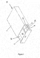
Figure 1 is a perspective view of a drawer in accordance with a first preferred embodiment of the present invention; -
Figure 2 is a perspective exploded view of the drawer ofFigure 1 ; -
Figure 3 is a transverse sectional view of the drawer ofFigure 1 ; -
Figure 4 is an enlarged view of a supplementary slide used in the drawer ofFigure 1 ; and -
Figure 5 is a perspective view of a supplementary drawer guide assembly used with the supplementary slide ofFigure 4 . - In the drawings like structures are referred to by like numerals throughout the several views. The drawings shown are not necessarily to scale, with emphasis instead generally being placed upon illustrating the principles of the present invention.
- With reference to a first preferred embodiment of the present invention as shown in
Figure 1 to Figure 5 , thecabinet drawer 11 of the first preferred embodiment comprises anouter cabinet housing 1, a slidingdrawer body 2 that is adapted to slide in and out of thecabinet housing 1, and drawer slide sets 8 mounted on thesides 15 of thedrawer body 2. - The drawer slide sets 8 include a receiving
portion 18 in the form of a channel mounted to the internal walls of the outer cabinet housing and an engagingportion 28 in the form of a rib adapted to sit inside thechannel portion 18. Therib 28 slides within thechannel portion 18 to move thedrawer 2 in and out of theouter cabinet housing 1. - Alternative arrangements for the drawer slides 8 are envisaged by the present invention. For example, differently profiled channels could be used or a telescoping slide could connect the
sides 15 to the internal side walls of the cabinet housing and still be within the scope of the present invention. - An inverted
U-shape channel 3 is located on thebase 14 of thedrawer 2. The invertedU-shaped channel 3 forms a channel matching and being able to slide against the sliding element fitted in an omega-shapedchannel 4. - The inverted
U-shape channel 3 is typically constructed as part of thebase 14 of thedrawer 2. - The
drawer 2 includes twosides 15 and abase 14. In the embodiment illustrated in the figures, thebase 14 extends between and is connected to the twosides 15. In alternative embodiments, intermediate portions can connect the base 14 to thesides 15. For example, an angled plate can connect the base 14 to the twosides 15. Other alternative arrangements of thesides 15 andbase 14 are considered by the present invention, provided that thebase 14 includes a guide channel and the base 14 connected to thesides 15 including drawer slides 8. - In one preferred embodiment of the present invention the inverted
U-shaped channel 3 is formed as part of thebase 14 of thedrawer 2. Alternatively, theU-shaped channel 3 can be a separate piece that is attached to thebase 14, through welding, screwing, or otherwise as would be understood by the skilled addressee. - In one preferred embodiment of the present invention the drawer slide sets 8 are formed as part of the
sides 15 of thedrawer 2. Alternatively, drawer slide sets 8 can be a separate piece that is attached to thesides 15, through welding, screwing, or otherwise as would be understood by the skilled addressee. - In one preferred embodiment the
U-shaped channel 3 is located at the mid-point across the width of thedrawer 2. Alternatively theU-shaped channel 3 can be located at any point across the width of thedrawer 2. There can be a plurality ofU-shaped channels 3 in thebase 14 of thedrawer 2. - An omega-shaped
channel 4 piece is adapted to be mounting onto the internal face of thecabinet 1 which thedrawer 2 sits on and is located to slidingly engage with theU-shaped channel 3. Omega shapedchannel 4 consists of rectangular shapedholes 5 on its faces, through which a portion ofball bearings 6 and 7 pass through. The portion of the ball bearings 6 that extends outside the omega shapedchannel 4 is in contact with the vertical inner faces 23 of the inverted U-channel 3, and constrains the sideway movement of thedrawer 2. The portion ofball bearings 7 that extends outside the omega shaped channel is in contact with thehorizontal underside 13 of the invertedU-shape channel 3, and provides support to the load in the slidingdrawer 2. - The omega-shaped
channel 4 can be mounted to the internal face of thecabinet 1, through welding, snap fitting, clips, screwing or otherwise as would be understood by the skilled addressee. - It is within the scope of the present invention to use an alternative sliding guide structure to the omega-shaped
channel 4. Rollers, or other devices understood by the skilled addressee may be attached to the inside of thecabinet 1 to coincide with and run along theU-shaped channel 3. - The inverted
U-shaped channel 3 that is configured on the base panel of thedrawer 2 provides reinforcement to the base panel and avoids sagging of thebase 14 andother drawer 2 panels under heavy load. Consequently, minimum clearance can be achieved between the underside of thedrawer 2 and the inner bottom face ofcabinet 1. This increases the effective storage volume of the drawer. Also, bearings 6 are arranged in such a way that obeys the "narrow guide principle", ensuring that the sideward swing of the drawer is kept to the minimum. - Whilst the
channel 3 has been described as U-shaped, the present invention envisages alternative shapes such as V, funnel, tapered or otherwise as would be understood by the skilled addressee. - Modifications and variations such as would be apparent to the skilled addressee are considered to fall within the scope of the present invention. The present invention is not to be limited in scope by any of the specific embodiments described herein. These embodiments are intended for the purpose of exemplification only. Functionally equivalent products, formulations and methods are clearly within the scope of the invention as described herein.
- Reference to positional descriptions, such as lower and upper, are to be taken in context of the embodiments depicted in the figures, and are not to be taken as limiting the invention to the literal interpretation of the term but rather as would be understood by the skilled addressee.
- Throughout this specification, unless the context requires otherwise, the word "comprise" or variations such as "comprises" or "comprising", will be understood to imply the inclusion of a stated integer or group of integers but not the exclusion of any other integer or group of integers.
Claims (15)
- A cabinet drawer comprising a cabinet and a sliding drawer; wherein the sliding drawer is mounted with two sets of sliding guides on two opposite sides of the drawer, and a supplementary sliding guide on a face of the drawer located between the two opposite sides.
- The cabinet drawer as claimed in Claim 1, wherein the two opposite sides are located on sides of the drawer.
- The cabinet drawer as claimed in Claim 1, wherein the face of the drawer is perpendicular to the opposite sides.
- The cabinet drawer as claimed in Claim 1, wherein the face of the drawer connects the opposite sides together, and is preferably on the base of the drawer..
- The cabinet drawer as claimed in Claim 1, wherein the supplementary sliding guide is located at the mid-point of the face.
- The cabinet drawer as claimed in Claim 1, wherein the supplementary sliding guide comprises a channel in which anti-friction bearings, rollers or pads are received.
- The cabinet drawer as claimed in Claim 6, wherein the bearings, rollers or pads slide on the inner faces of an inverted U-shaped channel.
- The cabinet drawer as claimed in Claim 7, wherein the inverted U-shaped channel is built onto the bottom face of the drawer, and is preferably integrally formed with the drawer body.
- The cabinet drawer as claimed in Claim 6, wherein the bearings, rollers or pads are fixed to a face of the cabinet.
- The cabinet drawer as claimed in Claim 9, wherein the bearings, rollers or pads are fixed to the face of the cabinet so that the sliding guide aligns with the bearings, rollers or pads in use.
- The cabinet drawer as claimed in Claim 6, wherein the bearings, rollers or pads are located within an omega-shaped channel.
- The cabinet drawer as claimed in Claim 1, wherein each of two sets of sliding guides includes an engaging portion on the drawer and a receiving portion on the cabinet.
- The cabinet drawer as claimed in Claim 12, wherein the engaging portion is adapted to be received within and run along the receiving portion in use.
- The cabinet drawer as claimed in any one of the preceding claims, including a plurality of the supplementary sliding guides.
- The cabinet drawer as claimed in any one of the preceding claims, wherein each of the two sets of sliding guides and the supplementary sliding guide support the weight of the drawer.
Applications Claiming Priority (1)
| Application Number | Priority Date | Filing Date | Title |
|---|---|---|---|
| AU2014240336A AU2014240336A1 (en) | 2014-10-07 | 2014-10-07 | Improved cabinet drawer |
Publications (1)
| Publication Number | Publication Date |
|---|---|
| EP3005902A1 true EP3005902A1 (en) | 2016-04-13 |
Family
ID=54291093
Family Applications (1)
| Application Number | Title | Priority Date | Filing Date |
|---|---|---|---|
| EP15188458.2A Withdrawn EP3005902A1 (en) | 2014-10-07 | 2015-10-06 | Improved cabinet drawer |
Country Status (3)
| Country | Link |
|---|---|
| US (1) | US20160183681A1 (en) |
| EP (1) | EP3005902A1 (en) |
| AU (1) | AU2014240336A1 (en) |
Citations (10)
| Publication number | Priority date | Publication date | Assignee | Title |
|---|---|---|---|---|
| US3328107A (en) | 1966-09-14 | 1967-06-27 | Kenneth H Gutner | Drawer glide |
| US3649086A (en) | 1970-11-27 | 1972-03-14 | Winzeler Stamping Co | Drawer guide |
| US3797906A (en) | 1973-03-09 | 1974-03-19 | K Gutner | Drawer slide having novel front panel connection |
| US3981553A (en) | 1975-12-05 | 1976-09-21 | Gutner Kenneth H | Drawer slide |
| US4285560A (en) * | 1979-09-24 | 1981-08-25 | Schwab Safe Co., Inc. | Anti-racking device |
| US4387942A (en) | 1980-11-28 | 1983-06-14 | Amerock Corporation | Drawer slide assembly |
| US4441773A (en) | 1982-02-08 | 1984-04-10 | Hardware Designers, Inc. | Bottom mounted drawer slide assembly |
| US4659237A (en) | 1984-12-20 | 1987-04-21 | Julius Blum Gesellschaft M.B.H. | Drawer guide |
| DE202008010779U1 (en) * | 2008-08-13 | 2009-12-24 | Paul Hettich Gmbh & Co. Kg | Pull-out guide for a furniture pull-out part |
| US20120262044A1 (en) * | 2011-04-18 | 2012-10-18 | General Electric Company | Consumer appliance drawer with improved anti-racking system |
-
2014
- 2014-10-07 AU AU2014240336A patent/AU2014240336A1/en not_active Abandoned
-
2015
- 2015-10-01 US US14/872,229 patent/US20160183681A1/en not_active Abandoned
- 2015-10-06 EP EP15188458.2A patent/EP3005902A1/en not_active Withdrawn
Patent Citations (10)
| Publication number | Priority date | Publication date | Assignee | Title |
|---|---|---|---|---|
| US3328107A (en) | 1966-09-14 | 1967-06-27 | Kenneth H Gutner | Drawer glide |
| US3649086A (en) | 1970-11-27 | 1972-03-14 | Winzeler Stamping Co | Drawer guide |
| US3797906A (en) | 1973-03-09 | 1974-03-19 | K Gutner | Drawer slide having novel front panel connection |
| US3981553A (en) | 1975-12-05 | 1976-09-21 | Gutner Kenneth H | Drawer slide |
| US4285560A (en) * | 1979-09-24 | 1981-08-25 | Schwab Safe Co., Inc. | Anti-racking device |
| US4387942A (en) | 1980-11-28 | 1983-06-14 | Amerock Corporation | Drawer slide assembly |
| US4441773A (en) | 1982-02-08 | 1984-04-10 | Hardware Designers, Inc. | Bottom mounted drawer slide assembly |
| US4659237A (en) | 1984-12-20 | 1987-04-21 | Julius Blum Gesellschaft M.B.H. | Drawer guide |
| DE202008010779U1 (en) * | 2008-08-13 | 2009-12-24 | Paul Hettich Gmbh & Co. Kg | Pull-out guide for a furniture pull-out part |
| US20120262044A1 (en) * | 2011-04-18 | 2012-10-18 | General Electric Company | Consumer appliance drawer with improved anti-racking system |
Also Published As
| Publication number | Publication date |
|---|---|
| AU2014240336A1 (en) | 2016-04-21 |
| US20160183681A1 (en) | 2016-06-30 |
Similar Documents
| Publication | Publication Date | Title |
|---|---|---|
| US4659237A (en) | Drawer guide | |
| US8277003B2 (en) | Undermount drawer slide | |
| US9095213B2 (en) | Sliding device | |
| US8251465B2 (en) | Slide rail structure | |
| US8499496B2 (en) | Sliding door system | |
| EP2438834B1 (en) | Reinforcement and adjustment device for slide assembly | |
| EP2446779B1 (en) | Slide assembly with quick-mount system | |
| US9427084B2 (en) | Rail | |
| US20120087605A1 (en) | Reinforcement device for slide assembly | |
| US8231188B1 (en) | Support mechanism for slide assembly | |
| US11116316B2 (en) | Supporting device for rail member | |
| RU2664222C2 (en) | Pull-out guide for movable furniture parts | |
| US8740321B2 (en) | Slide rail | |
| US20070063626A1 (en) | Drawer assembly with roller bearings | |
| US7396092B2 (en) | Sliding guide for drawers and other furniture parts slide out of the body of a piece of furniture | |
| US7124902B1 (en) | Rack with linear guide | |
| JP2009112409A (en) | Slide rail | |
| EP3005902A1 (en) | Improved cabinet drawer | |
| WO2011052024A1 (en) | Slide rail | |
| ITTO971050A1 (en) | EXTRACTION DEVICE FOR HIGH CABINETS. | |
| CN105113933A (en) | Adjustable-inclination suspended rail door and triplex rail door comprising same | |
| CN204483536U (en) | Sliding guide rail system | |
| US20140145578A1 (en) | Slider for sanitary module, and sanitary module having slider | |
| CN106175139B (en) | A kind of pin-connected panel compact shelving track | |
| JP2015519490A (en) | Fitting |
Legal Events
| Date | Code | Title | Description |
|---|---|---|---|
| PUAI | Public reference made under article 153(3) epc to a published international application that has entered the european phase |
Free format text: ORIGINAL CODE: 0009012 |
|
| AK | Designated contracting states |
Kind code of ref document: A1 Designated state(s): AL AT BE BG CH CY CZ DE DK EE ES FI FR GB GR HR HU IE IS IT LI LT LU LV MC MK MT NL NO PL PT RO RS SE SI SK SM TR |
|
| AX | Request for extension of the european patent |
Extension state: BA ME |
|
| STAA | Information on the status of an ep patent application or granted ep patent |
Free format text: STATUS: THE APPLICATION IS DEEMED TO BE WITHDRAWN |
|
| 18D | Application deemed to be withdrawn |
Effective date: 20161014 |