EP3005876B1 - Follower for a stuffing horn assembly - Google Patents
Follower for a stuffing horn assembly Download PDFInfo
- Publication number
- EP3005876B1 EP3005876B1 EP15192585.6A EP15192585A EP3005876B1 EP 3005876 B1 EP3005876 B1 EP 3005876B1 EP 15192585 A EP15192585 A EP 15192585A EP 3005876 B1 EP3005876 B1 EP 3005876B1
- Authority
- EP
- European Patent Office
- Prior art keywords
- insert
- bore
- opening
- sidewall
- follower
- Prior art date
- Legal status (The legal status is an assumption and is not a legal conclusion. Google has not performed a legal analysis and makes no representation as to the accuracy of the status listed.)
- Active
Links
Images



Classifications
-
- A—HUMAN NECESSITIES
- A22—BUTCHERING; MEAT TREATMENT; PROCESSING POULTRY OR FISH
- A22C—PROCESSING MEAT, POULTRY, OR FISH
- A22C11/00—Sausage making ; Apparatus for handling or conveying sausage products during manufacture
- A22C11/02—Sausage filling or stuffing machines
- A22C11/0209—Stuffing horn assembly
-
- A—HUMAN NECESSITIES
- A22—BUTCHERING; MEAT TREATMENT; PROCESSING POULTRY OR FISH
- A22C—PROCESSING MEAT, POULTRY, OR FISH
- A22C11/00—Sausage making ; Apparatus for handling or conveying sausage products during manufacture
- A22C11/02—Sausage filling or stuffing machines
- A22C11/0245—Controlling devices
-
- A—HUMAN NECESSITIES
- A41—WEARING APPAREL
- A41D—OUTERWEAR; PROTECTIVE GARMENTS; ACCESSORIES
- A41D13/00—Professional, industrial or sporting protective garments, e.g. surgeons' gowns or garments protecting against blows or punches
- A41D13/05—Professional, industrial or sporting protective garments, e.g. surgeons' gowns or garments protecting against blows or punches protecting only a particular body part
- A41D13/08—Arm or hand
- A41D13/081—Hand protectors
- A41D13/087—Hand protectors especially for fingers
-
- A—HUMAN NECESSITIES
- A45—HAND OR TRAVELLING ARTICLES
- A45D—HAIRDRESSING OR SHAVING EQUIPMENT; EQUIPMENT FOR COSMETICS OR COSMETIC TREATMENTS, e.g. FOR MANICURING OR PEDICURING
- A45D29/00—Manicuring or pedicuring implements
-
- A—HUMAN NECESSITIES
- A45—HAND OR TRAVELLING ARTICLES
- A45D—HAIRDRESSING OR SHAVING EQUIPMENT; EQUIPMENT FOR COSMETICS OR COSMETIC TREATMENTS, e.g. FOR MANICURING OR PEDICURING
- A45D44/00—Other cosmetic or toiletry articles, e.g. for hairdressers' rooms
Definitions
- This invention is directed to a follower for a cylinder.
- Elongated hollow stuffing tubes are well-known in the art.
- the tubes serve as a conduit upon which a hollow elongated casing material is mounted and through which meat emulsion is pumped for delivery into the casing.
- the attachment of a stuffing tube for operation has created challenges in the past which initially were addressed in U.S. Patent Nos. 6,135,870 and 6,315,653 . While these patents represented an improvement, challenges still remained as the stuffing tube mounting assemblies were designed to match only one size of stuffing tube. To replace the tube was time consuming.
- an objective of this invention is to provide a mounting assembly that accommodates different sizes of stuffing horns.
- Another objective of this invention is to provide a mounting assembly that allows for greater speed and ease in substituting stuffing horns.
- a still further objective of this invention is to provide a follower that reduces and/or eliminates the build-up of meat emulsion inside a cylinder.
- a follower for a stuffing horn assembly according to claim 1 and a horn adjustment assembly according to claim 8 are disclosed.
- the follower has a housing having a bore. An opening in a sidewall of the housing is in communication with the bore. Disposed within the bore is a wiper. A cap having a central opening in an end wall is attached to the housing.
- a stuffing tube mounting assembly 10 includes an elongated member 12, a stuffing horn 14, and a collar 16.
- the elongated member 12 has a first section 18, an intermediate section 20, and a second section 22.
- the first section is designed for connection to the air cylinder 23 for moving the mounting assembly in a longitudinal direction.
- the first section 18 has an end 24 that tapers outwardly from the end 24 and terminates at first connecting flange 26.
- the connecting flange 26 is separated from a second flange 28 by an elongated section 30.
- the second flange 28 is greater in diameter than the first flange 26 and has flat surfaces 32 for gripping with a vice.
- the intermediate section 20 of the elongated member 12 Extending outwardly and away from the second flange 28 is the intermediate section 20 of the elongated member 12.
- the intermediate section 20 is generally cylindrical with indented flat surfaces 34 that are used for gripping with a wrench.
- the second section 22 Extending outwardly and away from the intermediate section 20 is the second section 22.
- the second section 22 has a central threaded portion 36 with no physical stops beside the taper, a first tapered portion 38 that tapers outwardly from the intermediate section 20 toward the central portion 36, and a second tapered portion 40 that tapers inwardly from the central portion 36 toward end 42.
- the first section 18 and second section 22 have outer surfaces concentric with the longitudinal center axis 44 of the elongated member 12.
- the stuffing horn 14 is hollow and has a tapered portion 46 that tapers outwardly from the primary portion 48 of the horn 14 toward a connecting end 50.
- the angle of the taper of tapered portion 46 is similar to the angle of tapered portion 40 such that portion 46 fits over and engages portion 40 along the tapered surface.
- the collar 16 has a first end 52, a second end 54, and a concentric bore 56 that extends longitudinally there through.
- the bore has a first section 58 that has a diameter larger than the stuffing horn 14.
- Extending away and tapering outwardly from the first section 58 is a second section 60 of the bore 56.
- the angle of the taper of section 60 of the bore 56 is similar to the angle of the tapered portion 46 of the stuffing horn such that the second section 60 of bore 56 fits over and engages portion 46 along the tapered surface.
- the second section 60 terminates in a threaded third section 62 of bore 56.
- the third section 62 has a diameter slightly larger than the diameter of central portion 36 of the elongated member 12 such that the third section 62 of the bore 56 is threadably received upon the central portion 36 of the elongated member 12.
- the end opposite the connecting end 50 of the stuffing horn 14 is inserted through bore 56 of the collar 16.
- the collar is moved along the length of the primary portion 48 of the stuffing horn 14 until the collar 16 reaches the tapered portion 46 of the stuffing horn 14.
- the tapered portion 40 of the second section 22 of member 12 is inserted into tapered portion 46 of stuffing horn 14 such that the outer surface of portion 40 engages the inner surface of portion 46.
- the collar 16 is then threadably connected to the second section 22 by the threads of the third section 62 of the collar 16 are received by the threaded portion 36 of the second section 22.
- the second section 60 of the collar and the tapered portion 40 of the second section are drawn into engagement with tapered portion 46 of the stuffing horn 14 to create a seal.
- the stuffing horn 14 is longitudinally moveable by a horn adjustment assembly that includes a cylinder 65 that extends through a follower 66.
- the follower has a housing 68, an insert 70, and a cap 72.
- the housing has a first end 74, a second end 76, a sidewall 78, and a bore 80 that generally extends through the central axis of the housing 68 from the first end 74 to the second end 76.
- a transversely extending shelf 81 Positioned within the bore 80 is a transversely extending shelf 81 that has an opening 83 with a diameter less than the diameter of the insert 70.
- the sidewall 78 has at least one opening 82 that extends from the outer perimeter of the sidewall 78 to bore 80.
- the opening 82 is connected to and in communication with a source of pressurized grease 85.
- the sidewall 78 has a reduced area 84 that forms a shoulder 86. Extending outwardly from shoulder 86 is
- the insert 70 has a first end 90, a second end 92, a sidewall 94, and a bore 96 that is generally centrally located.
- the sidewall 94 has at least one and preferably multiple openings 98.
- the sidewall 94 also has a diameter less than the diameter of bore 80.
- Attached to the second end 92 of the insert 70 is a wiper 100.
- the wiper 100 is mounted within bore 96, is made of a pliable material such as rubber or the like, and has a central opening 102.
- the wiper is mounted to stem 88.
- the cap 72 has an end wall 104 and a sidewall 106.
- the end wall has a generally centrally located opening 108 that has a diameter smaller than the diameter of the insert.
- the sidewall 106 has a threaded inner surface 110 that is threadably received on the threaded stem 88 of the housing 68.
- the insert 70 is inserted into bore 80 at the second end of the housing 68 until the first end 90 of the insert 70 engages shelf 81.
- the cap 72 is threadably attached to the housing 68 such that opening 83 of the shelf 81, bore 96 of the insert 70, and opening 102 of the wiper 100 are in alignment.
- the follower 66 is then positioned such that cylinder 65 is inserted through openings 83, bore 96 and opening 102.
- a wiper 111 alternatively and/or additionally is mounted at end 90 of insert 70 to prevent grease from entering cylinder 65.
Landscapes
- Engineering & Computer Science (AREA)
- Life Sciences & Earth Sciences (AREA)
- Wood Science & Technology (AREA)
- Zoology (AREA)
- Food Science & Technology (AREA)
- Textile Engineering (AREA)
- General Health & Medical Sciences (AREA)
- Physical Education & Sports Medicine (AREA)
- Health & Medical Sciences (AREA)
- Containers And Plastic Fillers For Packaging (AREA)
- Processing Of Meat And Fish (AREA)
- Coating Apparatus (AREA)
- Infusion, Injection, And Reservoir Apparatuses (AREA)
- Nozzles (AREA)
- Package Closures (AREA)
- Actuator (AREA)
Description
- This invention is directed to a follower for a cylinder.
- Elongated hollow stuffing tubes are well-known in the art. The tubes serve as a conduit upon which a hollow elongated casing material is mounted and through which meat emulsion is pumped for delivery into the casing. The attachment of a stuffing tube for operation has created challenges in the past which initially were addressed in
U.S. Patent Nos. 6,135,870 and6,315,653 . While these patents represented an improvement, challenges still remained as the stuffing tube mounting assemblies were designed to match only one size of stuffing tube. To replace the tube was time consuming. - In addition, when the stuffing tube would be moved by an air cylinder, meat emulsion would build up on the cylinder affecting operation and requiring cleaning. Accordingly, a need exists in the art for a device that addressed these deficiencies.
- Therefore, an objective of this invention is to provide a mounting assembly that accommodates different sizes of stuffing horns.
- Another objective of this invention is to provide a mounting assembly that allows for greater speed and ease in substituting stuffing horns.
- A still further objective of this invention is to provide a follower that reduces and/or eliminates the build-up of meat emulsion inside a cylinder.
- These and other objectives will be apparent to one of skill in the art based on the following written description, drawings, and claims.
- A follower for a stuffing horn assembly according to claim 1 and a horn adjustment assembly according to claim 8 are disclosed. The follower has a housing having a bore. An opening in a sidewall of the housing is in communication with the bore. Disposed within the bore is a wiper. A cap having a central opening in an end wall is attached to the housing.
-
-
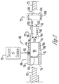
Fig. 1 is an exploded sectional view of a mounting assembly; -
Fig. 2 is a perspective view of a mounting assembly; -
Fig. 3 is an exploded sectional view of a follower; and -
Fig. 4 is a perspective view of a follower. - Referring to the Figures, a stuffing
tube mounting assembly 10 includes an elongated member 12, astuffing horn 14, and acollar 16. The elongated member 12 has afirst section 18, anintermediate section 20, and asecond section 22. The first section is designed for connection to theair cylinder 23 for moving the mounting assembly in a longitudinal direction. Preferably, thefirst section 18 has anend 24 that tapers outwardly from theend 24 and terminates at first connectingflange 26. The connectingflange 26 is separated from asecond flange 28 by anelongated section 30. Preferably, thesecond flange 28 is greater in diameter than thefirst flange 26 and hasflat surfaces 32 for gripping with a vice. - Extending outwardly and away from the
second flange 28 is theintermediate section 20 of the elongated member 12. Preferably, theintermediate section 20 is generally cylindrical with indentedflat surfaces 34 that are used for gripping with a wrench. - Extending outwardly and away from the
intermediate section 20 is thesecond section 22. Preferably, thesecond section 22 has a central threadedportion 36 with no physical stops beside the taper, a firsttapered portion 38 that tapers outwardly from theintermediate section 20 toward thecentral portion 36, and a secondtapered portion 40 that tapers inwardly from thecentral portion 36 toward end 42. Thefirst section 18 andsecond section 22 have outer surfaces concentric with thelongitudinal center axis 44 of the elongated member 12. - The
stuffing horn 14 is hollow and has a tapered portion 46 that tapers outwardly from theprimary portion 48 of thehorn 14 toward a connectingend 50. The angle of the taper of tapered portion 46 is similar to the angle oftapered portion 40 such that portion 46 fits over and engagesportion 40 along the tapered surface. - The
collar 16 has afirst end 52, a second end 54, and aconcentric bore 56 that extends longitudinally there through. The bore has afirst section 58 that has a diameter larger than the stuffinghorn 14. Extending away and tapering outwardly from thefirst section 58 is asecond section 60 of thebore 56. Preferably, the angle of the taper ofsection 60 of thebore 56 is similar to the angle of the tapered portion 46 of the stuffing horn such that thesecond section 60 of bore 56 fits over and engages portion 46 along the tapered surface. Thesecond section 60 terminates in a threadedthird section 62 ofbore 56. Thethird section 62 has a diameter slightly larger than the diameter ofcentral portion 36 of the elongated member 12 such that thethird section 62 of thebore 56 is threadably received upon thecentral portion 36 of the elongated member 12. - To assemble, the end opposite the connecting
end 50 of thestuffing horn 14 is inserted throughbore 56 of thecollar 16. The collar is moved along the length of theprimary portion 48 of thestuffing horn 14 until thecollar 16 reaches the tapered portion 46 of thestuffing horn 14. Next, thetapered portion 40 of thesecond section 22 of member 12 is inserted into tapered portion 46 ofstuffing horn 14 such that the outer surface ofportion 40 engages the inner surface of portion 46. Thecollar 16 is then threadably connected to thesecond section 22 by the threads of thethird section 62 of thecollar 16 are received by the threadedportion 36 of thesecond section 22. As thecollar 16 is connected to thesecond section 22, thesecond section 60 of the collar and thetapered portion 40 of the second section are drawn into engagement with tapered portion 46 of thestuffing horn 14 to create a seal. - The
stuffing horn 14 is longitudinally moveable by a horn adjustment assembly that includes acylinder 65 that extends through afollower 66. Preferably, the follower has ahousing 68, aninsert 70, and acap 72. The housing has afirst end 74, asecond end 76, asidewall 78, and a bore 80 that generally extends through the central axis of thehousing 68 from thefirst end 74 to thesecond end 76. Positioned within the bore 80 is a transversely extendingshelf 81 that has anopening 83 with a diameter less than the diameter of theinsert 70. Thesidewall 78 has at least one opening 82 that extends from the outer perimeter of thesidewall 78 to bore 80. The opening 82 is connected to and in communication with a source ofpressurized grease 85. Thesidewall 78 has a reducedarea 84 that forms ashoulder 86. Extending outwardly fromshoulder 86 is a threadedstem 88. - The
insert 70 has a first end 90, a second end 92, asidewall 94, and abore 96 that is generally centrally located. Thesidewall 94 has at least one and preferablymultiple openings 98. Thesidewall 94 also has a diameter less than the diameter of bore 80. Attached to the second end 92 of theinsert 70 is a wiper 100. Preferably the wiper 100 is mounted withinbore 96, is made of a pliable material such as rubber or the like, and has acentral opening 102. Alternatively, the wiper is mounted to stem 88. - The
cap 72 has anend wall 104 and asidewall 106. The end wall has a generally centrally located opening 108 that has a diameter smaller than the diameter of the insert. Thesidewall 106 has a threadedinner surface 110 that is threadably received on the threadedstem 88 of thehousing 68. - To assemble, the
insert 70 is inserted into bore 80 at the second end of thehousing 68 until the first end 90 of theinsert 70 engagesshelf 81. Once inserted, thecap 72 is threadably attached to thehousing 68 such that opening 83 of theshelf 81, bore 96 of theinsert 70, and opening 102 of the wiper 100 are in alignment. Thefollower 66 is then positioned such thatcylinder 65 is inserted throughopenings 83, bore 96 andopening 102. - Once assembled, grease is supplied to the
follower 66 from the source ofpressurized grease 85. The grease flows from itssource 85 throughopening 82 and into bore 80. From bore 80 the grease flows throughopenings 98 of the insert and onto thecylinder 65. As thecylinder 65 is slid toward the stuffinghorn 14 the grease on thecylinder 65 resists the build-up of meat. As thecylinder 65 is pulled away from the stuffinghorn 14, any meat left on the cylinder is removed by the wiper 100. Awiper 111 alternatively and/or additionally is mounted at end 90 ofinsert 70 to prevent grease from enteringcylinder 65. - Accordingly, a stuffing tube mounting assembly and follower have been disclosed that, at the very least, meet the stated objectives.
Claims (8)
- Follower (66) for a stuffing horn assembly (10), comprising:- a housing (68), having a first end (74), a second end (76), a sidewall (78) and a bore (80);- wherein positioned within the bore (80) is a transversely extending shelf (81) that has an opening (83);- wherein the sidewall (78) has at least one opening (82) that extends from the outer perimeter of the sidewall (78) to the bore (80), which opening (82) is connected to and in communication with a source of pressurized grease (85);- an insert (70) having a first end (90), a second end (92), a sidewall (94), a centrally located bore (96) and at least one opening in a sidewall (94) of the insert (70);- wherein the sidewall (94) of the insert has a diameter less than the diameter of the housing bore (80) and has at least one opening (98);- wherein a wiper (100) is attached to the second end (92) of the insert (70), which wiper (100) is mounted within the bore (96) of the insert (70) and has a central opening (102);- a cap (72), having an end wall (104) and a sidewall (106);- wherein the end wall (104) has an opening (108) with a diameter smaller than the diameter of the insert (70)- wherein the insert (70) is inserted into the housing bore (80) at the second end of the housing (68) until the first end (90) of the insert (70) engages the shelf (81), the cap (72) being threadably attached to the housing (68) such that the opening (83) of the shelf (81), the bore (96) of the insert (70) and the opening (102) of the wiper (100) are in alignment, wherein the opening (83) has a diameter less than the diameter of the insert (70),- wherein a cylinder (65) can be inserted through shelf opening (83), insert bore (96) and wiper opening (102); and- wherein grease can be supplied to the follower (66) from the source of pressurized grease (85), which grease flows from its source (85) through sidewall opening (82) into housing bore (80), and from the bore (80) through insert sidewall opening (98) onto the cylinder (65).
- Follower (66) according to claim 1, wherein the sidewall (78) of the housing (68) has a reduced area (84) that forms a shoulder (86), from which a threaded stem (88) extends outwardly
- Follower (66) according to any of the preceding claims, wherein the sidewall (94) of the insert (70) has multiple openings (98).
- Follower (66) according to any of the preceding claims, wherein the wiper (100) is made of a pliable material such as rubber.
- Follower (66) according to any of the preceding claims 2-4, wherein the wiper (100) is mounted to the stem (88) instead of within the bore (96) of the insert (70).
- Follower (66) according to any of the preceding claims 2-5, wherein the sidewall (106) of the cap (72) has a threaded inner surface (110) that is threadably received on the threaded stem (88) of the housing (68).
- Follower (66) according to any of the preceding claims, wherein a second wiper (111) is mounted at the end (90) of the insert (70), alternatively and/or additionally to the wiper (100).
- Horn adjustment assembly comprising a cylinder (65) and a follower (66) according to any of the preceding claims, through which the cylinder extends.
Applications Claiming Priority (3)
| Application Number | Priority Date | Filing Date | Title |
|---|---|---|---|
| US13/179,950 US8777702B2 (en) | 2011-07-11 | 2011-07-11 | Stuffing tube mounting assembly and follower |
| PCT/US2012/046064 WO2013009748A1 (en) | 2011-07-11 | 2012-07-10 | Stuffing tube mounting assembly and follower |
| EP12738318.0A EP2731442B1 (en) | 2011-07-11 | 2012-07-10 | Stuffing tube mounting assembly |
Related Parent Applications (2)
| Application Number | Title | Priority Date | Filing Date |
|---|---|---|---|
| EP12738318.0A Division EP2731442B1 (en) | 2011-07-11 | 2012-07-10 | Stuffing tube mounting assembly |
| EP12738318.0A Division-Into EP2731442B1 (en) | 2011-07-11 | 2012-07-10 | Stuffing tube mounting assembly |
Publications (2)
| Publication Number | Publication Date |
|---|---|
| EP3005876A1 EP3005876A1 (en) | 2016-04-13 |
| EP3005876B1 true EP3005876B1 (en) | 2018-10-17 |
Family
ID=46551902
Family Applications (2)
| Application Number | Title | Priority Date | Filing Date |
|---|---|---|---|
| EP12738318.0A Active EP2731442B1 (en) | 2011-07-11 | 2012-07-10 | Stuffing tube mounting assembly |
| EP15192585.6A Active EP3005876B1 (en) | 2011-07-11 | 2012-07-10 | Follower for a stuffing horn assembly |
Family Applications Before (1)
| Application Number | Title | Priority Date | Filing Date |
|---|---|---|---|
| EP12738318.0A Active EP2731442B1 (en) | 2011-07-11 | 2012-07-10 | Stuffing tube mounting assembly |
Country Status (7)
| Country | Link |
|---|---|
| US (1) | US8777702B2 (en) |
| EP (2) | EP2731442B1 (en) |
| JP (1) | JP6093956B2 (en) |
| BR (1) | BR112014000554B1 (en) |
| DK (2) | DK3005876T3 (en) |
| ES (2) | ES2706203T3 (en) |
| WO (1) | WO2013009748A1 (en) |
Family Cites Families (18)
| Publication number | Priority date | Publication date | Assignee | Title |
|---|---|---|---|---|
| US888305A (en) | 1907-04-05 | 1908-05-19 | Nat Specialty Mfg Company | Spout for sausage-stuffers. |
| US990547A (en) | 1910-04-23 | 1911-04-25 | Ernest C Gunuskey | Nozzle for sausage-stuffing machines. |
| US2660755A (en) * | 1952-03-04 | 1953-12-01 | Cincinnati Butchers Supply Co | Stuffer valve |
| US3091799A (en) * | 1960-11-03 | 1963-06-04 | Laval Separator Co De | Stuffing horn |
| US3473190A (en) * | 1965-10-05 | 1969-10-21 | Mayer & Co Inc O | Collagen fiber coated product and method and apparatus for forming same |
| NL7114628A (en) * | 1970-11-05 | 1972-05-09 | H Niedecker | |
| CH543236A (en) | 1971-10-13 | 1973-10-31 | Hoegger & Cie Ag C | Sausage filling - with automatic closure valve to prevent bubbles forming and meat escaping when shut off |
| DE8701006U1 (en) | 1987-01-22 | 1987-03-05 | Schlösser Fleischwarenfabrik GmbH & Co KG, 4836 Herzebrock | Brake for a packaging sleeve running off a filling tube |
| US4893377A (en) * | 1988-01-06 | 1990-01-16 | Delaware Capital Formation, Inc. | Stuffing horn turret machine |
| US5332267A (en) * | 1993-07-15 | 1994-07-26 | Harrison Donald G | Tube coupling |
| US5503438A (en) * | 1995-02-10 | 1996-04-02 | Swauger; Jonathan L. | Flared tube coupling having a disposable sealing boot |
| US6056634A (en) * | 1996-06-05 | 2000-05-02 | Handtmann Piereder Machinery Ltd. | Method and apparatus for forming uniform, thinly cohered products from chunks of meat |
| US5916019A (en) | 1998-06-08 | 1999-06-29 | Delaware Capital Formation, Inc. | Casing brake construction for sausage discharge horn |
| US6135870A (en) * | 1999-04-22 | 2000-10-24 | Townsend Engineering Company | Mounting assembly for detachably supporting stuffing tubes on sausage encasing machines |
| US6315653B1 (en) | 2000-07-14 | 2001-11-13 | Townsend Engineering Company | Mounting assembly for detachably supporting and orienting stuffing tubes on sausage encasing machines |
| US6729659B2 (en) * | 2001-09-11 | 2004-05-04 | Visteon Global Technologies, Inc. | Flare fitting assembly with metal-to-metal line seal |
| US7306511B2 (en) * | 2003-09-09 | 2007-12-11 | Tipper Tie, Inc. | Systems with interchangeable horns for producing encased products and related methods, computer program products and horn rotor assemblies |
| US7488243B2 (en) * | 2004-11-01 | 2009-02-10 | Tipper Tie, Inc. | Systems with horns that extend into netting chutes and having cooperating deruckers for producing encased products and related devices, methods and computer program products |
-
2011
- 2011-07-11 US US13/179,950 patent/US8777702B2/en active Active
-
2012
- 2012-07-10 DK DK15192585.6T patent/DK3005876T3/en active
- 2012-07-10 ES ES15192585T patent/ES2706203T3/en active Active
- 2012-07-10 EP EP12738318.0A patent/EP2731442B1/en active Active
- 2012-07-10 EP EP15192585.6A patent/EP3005876B1/en active Active
- 2012-07-10 WO PCT/US2012/046064 patent/WO2013009748A1/en not_active Ceased
- 2012-07-10 BR BR112014000554-0A patent/BR112014000554B1/en not_active IP Right Cessation
- 2012-07-10 ES ES12738318T patent/ES2776632T3/en active Active
- 2012-07-10 DK DK12738318.0T patent/DK2731442T3/en active
- 2012-07-10 JP JP2014520249A patent/JP6093956B2/en not_active Expired - Fee Related
Non-Patent Citations (1)
| Title |
|---|
| None * |
Also Published As
| Publication number | Publication date |
|---|---|
| EP3005876A1 (en) | 2016-04-13 |
| EP2731442A1 (en) | 2014-05-21 |
| JP2014520550A (en) | 2014-08-25 |
| US20130017770A1 (en) | 2013-01-17 |
| WO2013009748A1 (en) | 2013-01-17 |
| BR112014000554A2 (en) | 2017-02-14 |
| JP6093956B2 (en) | 2017-03-15 |
| EP2731442B1 (en) | 2019-12-18 |
| BR112014000554B1 (en) | 2019-07-02 |
| US8777702B2 (en) | 2014-07-15 |
| ES2776632T3 (en) | 2020-07-31 |
| ES2706203T3 (en) | 2019-03-27 |
| DK3005876T3 (en) | 2019-02-11 |
| DK2731442T3 (en) | 2020-03-23 |
Similar Documents
| Publication | Publication Date | Title |
|---|---|---|
| US6655372B1 (en) | Quick detachable gun barrel assembly | |
| EP3636188A3 (en) | Self-holding screw head | |
| EP3002496B1 (en) | Grease gun | |
| US20170120266A1 (en) | Structure of gyrating nozzle head spray gun | |
| CA2440556A1 (en) | Pneumatic paint ball marker, universal barrel, adapter and insert combination | |
| CN103950008A (en) | Screw locking suction nozzle mechanism | |
| MX2024010718A (en) | Candle filter support and plate assembly for polymer melts. | |
| EP2731442B1 (en) | Stuffing tube mounting assembly | |
| US9664314B2 (en) | Valve connector for a valve of an inflating device and adapter having the same | |
| US5924608A (en) | Oil container | |
| JP2016534947A5 (en) | Coupler portion of dip tube assembly and dispensing system including the coupler portion | |
| US9592641B2 (en) | Tire sealant bottle assembly | |
| CN211562543U (en) | Ozone water-gas mixing device | |
| US20080191060A1 (en) | Spray Gun | |
| TWM615533U (en) | Nozzle head and nozzle | |
| CN206561048U (en) | Pipe anti-flat tools and pipe processing equipment | |
| US20180362222A1 (en) | Dual Threaded Adapter | |
| CN218302978U (en) | Front plug of fishing rod | |
| CN203858402U (en) | Mounting tool for long lens cone inner lens | |
| USD983003S1 (en) | Screw driver bit | |
| CN208373363U (en) | A kind of overlength smoking nozzle | |
| CN208100995U (en) | A cleaning tool for extruder barrel | |
| CN206593531U (en) | A kind of air gun transmission mechanism and automatic air rifle | |
| CN105508656B (en) | A kind of manual sequence valve | |
| JP2005256946A (en) | Hose connecting means |
Legal Events
| Date | Code | Title | Description |
|---|---|---|---|
| PUAI | Public reference made under article 153(3) epc to a published international application that has entered the european phase |
Free format text: ORIGINAL CODE: 0009012 |
|
| AC | Divisional application: reference to earlier application |
Ref document number: 2731442 Country of ref document: EP Kind code of ref document: P |
|
| AK | Designated contracting states |
Kind code of ref document: A1 Designated state(s): AL AT BE BG CH CY CZ DE DK EE ES FI FR GB GR HR HU IE IS IT LI LT LU LV MC MK MT NL NO PL PT RO RS SE SI SK SM TR |
|
| 17P | Request for examination filed |
Effective date: 20160907 |
|
| RBV | Designated contracting states (corrected) |
Designated state(s): AL AT BE BG CH CY CZ DE DK EE ES FI FR GB GR HR HU IE IS IT LI LT LU LV MC MK MT NL NO PL PT RO RS SE SI SK SM TR |
|
| STAA | Information on the status of an ep patent application or granted ep patent |
Free format text: STATUS: EXAMINATION IS IN PROGRESS |
|
| 17Q | First examination report despatched |
Effective date: 20170630 |
|
| GRAP | Despatch of communication of intention to grant a patent |
Free format text: ORIGINAL CODE: EPIDOSNIGR1 |
|
| STAA | Information on the status of an ep patent application or granted ep patent |
Free format text: STATUS: GRANT OF PATENT IS INTENDED |
|
| INTG | Intention to grant announced |
Effective date: 20180511 |
|
| GRAS | Grant fee paid |
Free format text: ORIGINAL CODE: EPIDOSNIGR3 |
|
| GRAA | (expected) grant |
Free format text: ORIGINAL CODE: 0009210 |
|
| STAA | Information on the status of an ep patent application or granted ep patent |
Free format text: STATUS: THE PATENT HAS BEEN GRANTED |
|
| AC | Divisional application: reference to earlier application |
Ref document number: 2731442 Country of ref document: EP Kind code of ref document: P |
|
| AK | Designated contracting states |
Kind code of ref document: B1 Designated state(s): AL AT BE BG CH CY CZ DE DK EE ES FI FR GB GR HR HU IE IS IT LI LT LU LV MC MK MT NL NO PL PT RO RS SE SI SK SM TR |
|
| REG | Reference to a national code |
Ref country code: GB Ref legal event code: FG4D |
|
| REG | Reference to a national code |
Ref country code: CH Ref legal event code: EP |
|
| REG | Reference to a national code |
Ref country code: IE Ref legal event code: FG4D |
|
| REG | Reference to a national code |
Ref country code: DE Ref legal event code: R096 Ref document number: 602012052465 Country of ref document: DE Ref country code: AT Ref legal event code: REF Ref document number: 1052885 Country of ref document: AT Kind code of ref document: T Effective date: 20181115 |
|
| REG | Reference to a national code |
Ref country code: NL Ref legal event code: FP |
|
| REG | Reference to a national code |
Ref country code: DK Ref legal event code: T3 Effective date: 20190207 |
|
| REG | Reference to a national code |
Ref country code: LT Ref legal event code: MG4D |
|
| REG | Reference to a national code |
Ref country code: AT Ref legal event code: MK05 Ref document number: 1052885 Country of ref document: AT Kind code of ref document: T Effective date: 20181017 |
|
| REG | Reference to a national code |
Ref country code: ES Ref legal event code: FG2A Ref document number: 2706203 Country of ref document: ES Kind code of ref document: T3 Effective date: 20190327 |
|
| PG25 | Lapsed in a contracting state [announced via postgrant information from national office to epo] |
Ref country code: AT Free format text: LAPSE BECAUSE OF FAILURE TO SUBMIT A TRANSLATION OF THE DESCRIPTION OR TO PAY THE FEE WITHIN THE PRESCRIBED TIME-LIMIT Effective date: 20181017 Ref country code: LV Free format text: LAPSE BECAUSE OF FAILURE TO SUBMIT A TRANSLATION OF THE DESCRIPTION OR TO PAY THE FEE WITHIN THE PRESCRIBED TIME-LIMIT Effective date: 20181017 Ref country code: PL Free format text: LAPSE BECAUSE OF FAILURE TO SUBMIT A TRANSLATION OF THE DESCRIPTION OR TO PAY THE FEE WITHIN THE PRESCRIBED TIME-LIMIT Effective date: 20181017 Ref country code: HR Free format text: LAPSE BECAUSE OF FAILURE TO SUBMIT A TRANSLATION OF THE DESCRIPTION OR TO PAY THE FEE WITHIN THE PRESCRIBED TIME-LIMIT Effective date: 20181017 Ref country code: BG Free format text: LAPSE BECAUSE OF FAILURE TO SUBMIT A TRANSLATION OF THE DESCRIPTION OR TO PAY THE FEE WITHIN THE PRESCRIBED TIME-LIMIT Effective date: 20190117 Ref country code: NO Free format text: LAPSE BECAUSE OF FAILURE TO SUBMIT A TRANSLATION OF THE DESCRIPTION OR TO PAY THE FEE WITHIN THE PRESCRIBED TIME-LIMIT Effective date: 20190117 Ref country code: IS Free format text: LAPSE BECAUSE OF FAILURE TO SUBMIT A TRANSLATION OF THE DESCRIPTION OR TO PAY THE FEE WITHIN THE PRESCRIBED TIME-LIMIT Effective date: 20190217 Ref country code: LT Free format text: LAPSE BECAUSE OF FAILURE TO SUBMIT A TRANSLATION OF THE DESCRIPTION OR TO PAY THE FEE WITHIN THE PRESCRIBED TIME-LIMIT Effective date: 20181017 Ref country code: FI Free format text: LAPSE BECAUSE OF FAILURE TO SUBMIT A TRANSLATION OF THE DESCRIPTION OR TO PAY THE FEE WITHIN THE PRESCRIBED TIME-LIMIT Effective date: 20181017 |
|
| PG25 | Lapsed in a contracting state [announced via postgrant information from national office to epo] |
Ref country code: GR Free format text: LAPSE BECAUSE OF FAILURE TO SUBMIT A TRANSLATION OF THE DESCRIPTION OR TO PAY THE FEE WITHIN THE PRESCRIBED TIME-LIMIT Effective date: 20190118 Ref country code: SE Free format text: LAPSE BECAUSE OF FAILURE TO SUBMIT A TRANSLATION OF THE DESCRIPTION OR TO PAY THE FEE WITHIN THE PRESCRIBED TIME-LIMIT Effective date: 20181017 Ref country code: RS Free format text: LAPSE BECAUSE OF FAILURE TO SUBMIT A TRANSLATION OF THE DESCRIPTION OR TO PAY THE FEE WITHIN THE PRESCRIBED TIME-LIMIT Effective date: 20181017 Ref country code: AL Free format text: LAPSE BECAUSE OF FAILURE TO SUBMIT A TRANSLATION OF THE DESCRIPTION OR TO PAY THE FEE WITHIN THE PRESCRIBED TIME-LIMIT Effective date: 20181017 Ref country code: PT Free format text: LAPSE BECAUSE OF FAILURE TO SUBMIT A TRANSLATION OF THE DESCRIPTION OR TO PAY THE FEE WITHIN THE PRESCRIBED TIME-LIMIT Effective date: 20190217 |
|
| REG | Reference to a national code |
Ref country code: DE Ref legal event code: R097 Ref document number: 602012052465 Country of ref document: DE |
|
| PG25 | Lapsed in a contracting state [announced via postgrant information from national office to epo] |
Ref country code: CZ Free format text: LAPSE BECAUSE OF FAILURE TO SUBMIT A TRANSLATION OF THE DESCRIPTION OR TO PAY THE FEE WITHIN THE PRESCRIBED TIME-LIMIT Effective date: 20181017 |
|
| PLBE | No opposition filed within time limit |
Free format text: ORIGINAL CODE: 0009261 |
|
| STAA | Information on the status of an ep patent application or granted ep patent |
Free format text: STATUS: NO OPPOSITION FILED WITHIN TIME LIMIT |
|
| PG25 | Lapsed in a contracting state [announced via postgrant information from national office to epo] |
Ref country code: RO Free format text: LAPSE BECAUSE OF FAILURE TO SUBMIT A TRANSLATION OF THE DESCRIPTION OR TO PAY THE FEE WITHIN THE PRESCRIBED TIME-LIMIT Effective date: 20181017 Ref country code: EE Free format text: LAPSE BECAUSE OF FAILURE TO SUBMIT A TRANSLATION OF THE DESCRIPTION OR TO PAY THE FEE WITHIN THE PRESCRIBED TIME-LIMIT Effective date: 20181017 Ref country code: SM Free format text: LAPSE BECAUSE OF FAILURE TO SUBMIT A TRANSLATION OF THE DESCRIPTION OR TO PAY THE FEE WITHIN THE PRESCRIBED TIME-LIMIT Effective date: 20181017 Ref country code: SK Free format text: LAPSE BECAUSE OF FAILURE TO SUBMIT A TRANSLATION OF THE DESCRIPTION OR TO PAY THE FEE WITHIN THE PRESCRIBED TIME-LIMIT Effective date: 20181017 |
|
| 26N | No opposition filed |
Effective date: 20190718 |
|
| PG25 | Lapsed in a contracting state [announced via postgrant information from national office to epo] |
Ref country code: SI Free format text: LAPSE BECAUSE OF FAILURE TO SUBMIT A TRANSLATION OF THE DESCRIPTION OR TO PAY THE FEE WITHIN THE PRESCRIBED TIME-LIMIT Effective date: 20181017 |
|
| PGFP | Annual fee paid to national office [announced via postgrant information from national office to epo] |
Ref country code: GB Payment date: 20190729 Year of fee payment: 8 |
|
| PG25 | Lapsed in a contracting state [announced via postgrant information from national office to epo] |
Ref country code: MC Free format text: LAPSE BECAUSE OF FAILURE TO SUBMIT A TRANSLATION OF THE DESCRIPTION OR TO PAY THE FEE WITHIN THE PRESCRIBED TIME-LIMIT Effective date: 20181017 |
|
| REG | Reference to a national code |
Ref country code: CH Ref legal event code: PL |
|
| PG25 | Lapsed in a contracting state [announced via postgrant information from national office to epo] |
Ref country code: TR Free format text: LAPSE BECAUSE OF FAILURE TO SUBMIT A TRANSLATION OF THE DESCRIPTION OR TO PAY THE FEE WITHIN THE PRESCRIBED TIME-LIMIT Effective date: 20181017 |
|
| REG | Reference to a national code |
Ref country code: BE Ref legal event code: MM Effective date: 20190731 |
|
| PG25 | Lapsed in a contracting state [announced via postgrant information from national office to epo] |
Ref country code: LI Free format text: LAPSE BECAUSE OF NON-PAYMENT OF DUE FEES Effective date: 20190731 Ref country code: LU Free format text: LAPSE BECAUSE OF NON-PAYMENT OF DUE FEES Effective date: 20190710 Ref country code: BE Free format text: LAPSE BECAUSE OF NON-PAYMENT OF DUE FEES Effective date: 20190731 Ref country code: CH Free format text: LAPSE BECAUSE OF NON-PAYMENT OF DUE FEES Effective date: 20190731 |
|
| PG25 | Lapsed in a contracting state [announced via postgrant information from national office to epo] |
Ref country code: IE Free format text: LAPSE BECAUSE OF NON-PAYMENT OF DUE FEES Effective date: 20190710 |
|
| PGFP | Annual fee paid to national office [announced via postgrant information from national office to epo] |
Ref country code: DK Payment date: 20200729 Year of fee payment: 9 |
|
| GBPC | Gb: european patent ceased through non-payment of renewal fee |
Effective date: 20200710 |
|
| PG25 | Lapsed in a contracting state [announced via postgrant information from national office to epo] |
Ref country code: GB Free format text: LAPSE BECAUSE OF NON-PAYMENT OF DUE FEES Effective date: 20200710 |
|
| PG25 | Lapsed in a contracting state [announced via postgrant information from national office to epo] |
Ref country code: CY Free format text: LAPSE BECAUSE OF FAILURE TO SUBMIT A TRANSLATION OF THE DESCRIPTION OR TO PAY THE FEE WITHIN THE PRESCRIBED TIME-LIMIT Effective date: 20181017 |
|
| PG25 | Lapsed in a contracting state [announced via postgrant information from national office to epo] |
Ref country code: HU Free format text: LAPSE BECAUSE OF FAILURE TO SUBMIT A TRANSLATION OF THE DESCRIPTION OR TO PAY THE FEE WITHIN THE PRESCRIBED TIME-LIMIT; INVALID AB INITIO Effective date: 20120710 Ref country code: MT Free format text: LAPSE BECAUSE OF FAILURE TO SUBMIT A TRANSLATION OF THE DESCRIPTION OR TO PAY THE FEE WITHIN THE PRESCRIBED TIME-LIMIT Effective date: 20181017 |
|
| REG | Reference to a national code |
Ref country code: DK Ref legal event code: EBP Effective date: 20210731 |
|
| PG25 | Lapsed in a contracting state [announced via postgrant information from national office to epo] |
Ref country code: MK Free format text: LAPSE BECAUSE OF FAILURE TO SUBMIT A TRANSLATION OF THE DESCRIPTION OR TO PAY THE FEE WITHIN THE PRESCRIBED TIME-LIMIT Effective date: 20181017 |
|
| PG25 | Lapsed in a contracting state [announced via postgrant information from national office to epo] |
Ref country code: DK Free format text: LAPSE BECAUSE OF NON-PAYMENT OF DUE FEES Effective date: 20210731 |
|
| P01 | Opt-out of the competence of the unified patent court (upc) registered |
Effective date: 20230514 |
|
| PGFP | Annual fee paid to national office [announced via postgrant information from national office to epo] |
Ref country code: NL Payment date: 20250620 Year of fee payment: 14 |
|
| PGFP | Annual fee paid to national office [announced via postgrant information from national office to epo] |
Ref country code: FR Payment date: 20250620 Year of fee payment: 14 |
|
| PGFP | Annual fee paid to national office [announced via postgrant information from national office to epo] |
Ref country code: ES Payment date: 20250801 Year of fee payment: 14 |
|
| PGFP | Annual fee paid to national office [announced via postgrant information from national office to epo] |
Ref country code: DE Payment date: 20250620 Year of fee payment: 14 |
|
| PGFP | Annual fee paid to national office [announced via postgrant information from national office to epo] |
Ref country code: IT Payment date: 20250619 Year of fee payment: 14 |