EP3005804B1 - Procédé, dispositif et système permettant d'exécuter une communication sans fil dans un système de communication sans fil - Google Patents
Procédé, dispositif et système permettant d'exécuter une communication sans fil dans un système de communication sans fil Download PDFInfo
- Publication number
- EP3005804B1 EP3005804B1 EP14804687.3A EP14804687A EP3005804B1 EP 3005804 B1 EP3005804 B1 EP 3005804B1 EP 14804687 A EP14804687 A EP 14804687A EP 3005804 B1 EP3005804 B1 EP 3005804B1
- Authority
- EP
- European Patent Office
- Prior art keywords
- node
- uplink
- component carrier
- primary component
- base station
- Prior art date
- Legal status (The legal status is an assumption and is not a legal conclusion. Google has not performed a legal analysis and makes no representation as to the accuracy of the status listed.)
- Active
Links
- 238000004891 communication Methods 0.000 title claims description 70
- 238000000034 method Methods 0.000 title claims description 26
- 230000005540 biological transmission Effects 0.000 claims description 86
- 230000011664 signaling Effects 0.000 claims description 34
- 239000000969 carrier Substances 0.000 claims description 21
- 230000002776 aggregation Effects 0.000 claims description 20
- 238000004220 aggregation Methods 0.000 claims description 20
- 230000004931 aggregating effect Effects 0.000 claims 1
- 230000014509 gene expression Effects 0.000 description 18
- 230000006870 function Effects 0.000 description 8
- 238000012545 processing Methods 0.000 description 8
- 238000010586 diagram Methods 0.000 description 6
- 230000008054 signal transmission Effects 0.000 description 5
- 238000005265 energy consumption Methods 0.000 description 4
- 230000015654 memory Effects 0.000 description 4
- 230000009286 beneficial effect Effects 0.000 description 3
- 238000004364 calculation method Methods 0.000 description 3
- 238000009795 derivation Methods 0.000 description 3
- 230000003287 optical effect Effects 0.000 description 3
- 239000004065 semiconductor Substances 0.000 description 3
- 238000004590 computer program Methods 0.000 description 2
- 230000009977 dual effect Effects 0.000 description 2
- 238000005259 measurement Methods 0.000 description 2
- 230000008569 process Effects 0.000 description 2
- 238000011084 recovery Methods 0.000 description 2
- 230000006399 behavior Effects 0.000 description 1
- 230000008859 change Effects 0.000 description 1
- 230000001419 dependent effect Effects 0.000 description 1
- 238000005516 engineering process Methods 0.000 description 1
- 230000003993 interaction Effects 0.000 description 1
- 239000004973 liquid crystal related substance Substances 0.000 description 1
- 230000007774 longterm Effects 0.000 description 1
- 238000012986 modification Methods 0.000 description 1
- 230000004048 modification Effects 0.000 description 1
- 239000013307 optical fiber Substances 0.000 description 1
- 238000005457 optimization Methods 0.000 description 1
- 230000009467 reduction Effects 0.000 description 1
Images

Classifications
-
- H—ELECTRICITY
- H04—ELECTRIC COMMUNICATION TECHNIQUE
- H04W—WIRELESS COMMUNICATION NETWORKS
- H04W72/00—Local resource management
- H04W72/20—Control channels or signalling for resource management
- H04W72/21—Control channels or signalling for resource management in the uplink direction of a wireless link, i.e. towards the network
-
- H—ELECTRICITY
- H04—ELECTRIC COMMUNICATION TECHNIQUE
- H04L—TRANSMISSION OF DIGITAL INFORMATION, e.g. TELEGRAPHIC COMMUNICATION
- H04L5/00—Arrangements affording multiple use of the transmission path
- H04L5/0001—Arrangements for dividing the transmission path
- H04L5/0003—Two-dimensional division
- H04L5/0005—Time-frequency
- H04L5/0007—Time-frequency the frequencies being orthogonal, e.g. OFDM(A), DMT
- H04L5/001—Time-frequency the frequencies being orthogonal, e.g. OFDM(A), DMT the frequencies being arranged in component carriers
-
- H—ELECTRICITY
- H04—ELECTRIC COMMUNICATION TECHNIQUE
- H04L—TRANSMISSION OF DIGITAL INFORMATION, e.g. TELEGRAPHIC COMMUNICATION
- H04L5/00—Arrangements affording multiple use of the transmission path
- H04L5/003—Arrangements for allocating sub-channels of the transmission path
- H04L5/0032—Distributed allocation, i.e. involving a plurality of allocating devices, each making partial allocation
- H04L5/0035—Resource allocation in a cooperative multipoint environment
-
- H—ELECTRICITY
- H04—ELECTRIC COMMUNICATION TECHNIQUE
- H04L—TRANSMISSION OF DIGITAL INFORMATION, e.g. TELEGRAPHIC COMMUNICATION
- H04L5/00—Arrangements affording multiple use of the transmission path
- H04L5/003—Arrangements for allocating sub-channels of the transmission path
- H04L5/0053—Allocation of signaling, i.e. of overhead other than pilot signals
-
- H—ELECTRICITY
- H04—ELECTRIC COMMUNICATION TECHNIQUE
- H04W—WIRELESS COMMUNICATION NETWORKS
- H04W24/00—Supervisory, monitoring or testing arrangements
- H04W24/08—Testing, supervising or monitoring using real traffic
-
- H—ELECTRICITY
- H04—ELECTRIC COMMUNICATION TECHNIQUE
- H04W—WIRELESS COMMUNICATION NETWORKS
- H04W52/00—Power management, e.g. TPC [Transmission Power Control], power saving or power classes
- H04W52/04—TPC
- H04W52/06—TPC algorithms
- H04W52/14—Separate analysis of uplink or downlink
- H04W52/146—Uplink power control
-
- H—ELECTRICITY
- H04—ELECTRIC COMMUNICATION TECHNIQUE
- H04W—WIRELESS COMMUNICATION NETWORKS
- H04W52/00—Power management, e.g. TPC [Transmission Power Control], power saving or power classes
- H04W52/04—TPC
- H04W52/18—TPC being performed according to specific parameters
- H04W52/24—TPC being performed according to specific parameters using SIR [Signal to Interference Ratio] or other wireless path parameters
- H04W52/242—TPC being performed according to specific parameters using SIR [Signal to Interference Ratio] or other wireless path parameters taking into account path loss
-
- H—ELECTRICITY
- H04—ELECTRIC COMMUNICATION TECHNIQUE
- H04W—WIRELESS COMMUNICATION NETWORKS
- H04W28/00—Network traffic management; Network resource management
- H04W28/02—Traffic management, e.g. flow control or congestion control
- H04W28/08—Load balancing or load distribution
- H04W28/082—Load balancing or load distribution among bearers or channels
-
- Y—GENERAL TAGGING OF NEW TECHNOLOGICAL DEVELOPMENTS; GENERAL TAGGING OF CROSS-SECTIONAL TECHNOLOGIES SPANNING OVER SEVERAL SECTIONS OF THE IPC; TECHNICAL SUBJECTS COVERED BY FORMER USPC CROSS-REFERENCE ART COLLECTIONS [XRACs] AND DIGESTS
- Y02—TECHNOLOGIES OR APPLICATIONS FOR MITIGATION OR ADAPTATION AGAINST CLIMATE CHANGE
- Y02D—CLIMATE CHANGE MITIGATION TECHNOLOGIES IN INFORMATION AND COMMUNICATION TECHNOLOGIES [ICT], I.E. INFORMATION AND COMMUNICATION TECHNOLOGIES AIMING AT THE REDUCTION OF THEIR OWN ENERGY USE
- Y02D30/00—Reducing energy consumption in communication networks
- Y02D30/70—Reducing energy consumption in communication networks in wireless communication networks
Definitions
- the disclosure relates to the technical field of wireless communication, and particularly to a method for performing wireless communication in a wireless communication system, a wireless communication device and a wireless communication system.
- Carrier aggregation before LTE (Long Term Evolution) Rel-11 is carrier aggregation of a single base station node.
- An aggregated carrier of a terminal is constituted of one primary component carrier and at least one secondary component carrier.
- SIB2 System Information Block 2
- a PUCCH (Physical Uplink Control Channel) signal is transmitted on the uplink primary component carrier. Normally, only one uplink component carrier performs uplink data transmission. Change of the primary component carrier implies occurrence of a handoff behavior.
- the primary component carriers may include a downlink component carrier of the macro base station. If the uplink primary component carrier is still associated in accordance with the SIB2, then it cannot assist the macro base station in performing PUCCH shunting to alleviate the burden for an uplink control channel of a macro cell in a case where the base station and the low power node perform common baseband transmission.
- the macro base station and the low power node perform CoMP (Coordinated Multi-Point) transmission, and particularly for a case where the macro base station serves as an uplink receiving node, it is unable to perform accurate power control. Further, a solution that takes the macro base station as a receiving node to perform uplink power control is not beneficial to reduce energy consumption of UE (User Equipment).
- UE User Equipment
- the disclosure aims at providing a method for performing wireless communication in a wireless communication system according to claim 9 and a corresponding wireless communication device according to claim 1, which can improve the efficiency of uplink power control of a terminal and/or reduce the burden for uplink control channel transmission of a macro cell.
- Exemplary embodiments are provided to make the disclosure more detailed and sufficiently convey the scope thereof to those skilled in the art. Numerous specific details, such as examples of a specific component, a device and a method, are illustrated to provide a thorough understanding of the embodiments of the disclosure, It will be apparent to those skilled in the art that, the exemplary embodiments can be implemented in different ways without using the specific details, and the exemplary embodiments should not be interpreted as limiting the scope of the disclosure. In some exemplary embodiments, well-known processes, well-known structures and well-known technologies are not described in detail.
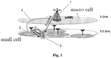
- a macro base station 1 has a wide coverage area which is referred as to a macro cell, and a low power node 2 has a narrow coverage area which is referred as to a small cell.
- the macro base station 1 has a frequency point of, for example, 2 GHz, and the low power node 2 has a frequency point of, for example, 3.5 GHz.
- Carrier aggregation may be performed between the macro base station 1 and the low power node 2.
- the macro base station 1 may be, for example, directly connected to the low power node 2 via an optical fiber 4, so that the macro base station 1 and the low power node 2 are in common baseband.
- UE (user equipment) 3 may communicate with both the macro base station 1 and the low power node 2 via multiple component carriers.
- the UE 3 has performed carrier aggregation between nodes of the macro base station 1 and the low power node 2, and the aggregated component carriers include a carrier a and a carrier b.
- the low power node 2 and the macro base station 1 perform CoMP (Cooperated Multi-Point) transmission for the UE 3 on the component carrier a, and the low power node separately serves the UE 3 on the carrier b.
- CoMP Cooperated Multi-Point
- the UE 3 may communicate with the macro base station 1 via a component carrier c, and communicate with the low power node 2 via a component carrier d.
- a carrier aggregation may be performed for the component carrier c and the component carrier d (carrier aggregation between nodes).
- association with an uplink primary component carrier may be performed via SIB2 transmitted by a downlink primary component carrier.
- the UE 3 may acknowledge an uplink primary component carrier via a default frequency point spacing between a downlink primary component carrier and the uplink primary component carrier associated with the downlink primary component carrier.
- TDD Time Division Duplex
- the primary component carriers may include a downlink component carrier of the macro base station 1.
- the primary component carriers will also include an uplink component carrier of the macro base station 1 based on the original primary component carrier setting and the association rules.
- uplink data transmission is generally performed on the uplink primary component carrier as much as possible. Therefore, in the case that the macro base station 1 and the low power node 2 perform common baseband transmission as shown in Fig. 1 , the low power node cannot assist the macro base station 1 in performing PUCCH shunting to alleviate the burden for an uplink control channel of a macro cell. Further, a solution that takes the macro base station 1 as a receiving node to perform uplink power control is not beneficial to reduce energy consumption of the UE 3.
- SRS Sounding Reference Signal
- PUCCH Physical Uplink Control Channel
- PUSCH Physical Uplink Shared Channel
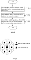
- an embodiment of the disclosure provides a method for performing wireless communication in a wireless communication system, as shown in Fig. 2 .
- the wireless communication system includes, for example, the low power node 2 and the macro base station 1 with common baseband and the UE 3 as shown in Fig. 1 , and the UE 3 communicates with the low power node 2 and the macro base station 1 via multiple component carriers.
- step S210 user equipment receives a downlink signal transmitted by the low power node and the macro base station.
- Fig. 1 the communication of the UE 3 with the macro base station 1 and the low power node 2 is schematically shown.
- the UE 3 is within the coverage area of the macro base station 1 and also within the coverage area of the low power node 2
- communication between the macro base station 1 and the UE 3 is performed via a C-plane (control plane)
- communication between the low power node 2 and the UE 3 is performed via a U-plane (user plane).
- uplink signals are transmitted to the low power node and the macro base station.
- the UE 3 may transmit an uplink signal to the low power node 2, and may also transmit an uplink signal to the macro base station 1.
- the first uplink signals here may include, but are not limited to, a PUCCH signal and/or a PUSCH signal.
- the method according to an embodiment of the disclosure transmits all of the first uplink signals, including the PUCCH signal and/or the PUSCH signal, to the low power node 2, to achieve shunting of the uplink signals, thereby alleviating the burden for an uplink control channel of the macro cell.
- the low power node 2 taken as a receiving node of some uplink signals may be beneficial to reduce energy consumption of the UE 3.
- the macro base station 1 sets a downlink component carrier thereof as a downlink primary component carrier.
- the method according to an embodiment of the disclosure may release the association between the uplink primary component carrier and the downlink primary component carrier. In other words, the original primary component carrier setting and the association rules are released. In this way, the PUCCH signal and the PUSCH signal will not be only transmitted on the default uplink primary component carrier of the macro base station 1.
- an uplink component carrier of the low power node 2 may be set as the uplink primary component carrier.
- the PUCCH signal and the PUSCH signal that are only transmitted on the uplink primary component carrier are transmitted to the low power node 2, thereby achieving shunting of the uplink signals.
- the transmission function of the downlink primary component carrier may be performed by a downlink timeslot of a component carrier of the macro base station 1, and the transmission function of the uplink primary component carrier may be performed by an uplink timeslot of a component carrier of the low power node 2.
- the PUCCH signal and the PUSCH signal may also be transmitted to the low power node 2, to achieve shunting of the uplink signals.
- the macro base station 1 may inform the UE 3 of the uplink primary component carrier on the low power node 2 via RRC (Radio Resource Control) signaling, MAC (Media Access Control) signaling or DCI (Downlink Control Information) of physical layer.
- RRC Radio Resource Control
- MAC Media Access Control
- DCI Downlink Control Information
- the UE 3 may know the uplink primary component carrier on the low power node 2 by receiving the the RRC signaling, the MAC signaling or DCI of the physical layer.
- the UE 3 may also select by default a component carrier with highest or lowest frequency point from these component carriers as the uplink primary component carrier of the UE 3 on the low power node 2.
- the macro base station 1 may inform to recover the association between the uplink primary component carrier and the downlink primary component carrier via the RRC signaling, the MAC signaling or the DCI of the physical layer.
- the UE 3 may be informed to recover the association between the uplink primary component carrier and the downlink primary component carrier by receiving the RRC signaling, the MAC signaling or the DCI of the physical layer.
- the UE 3 may also recover by default the association between the uplink primary component carrier and the downlink primary component carrier.
- An uplink component carrier of the macro base station 1 is set as the uplink primary component carrier after the association between the uplink primary component carrier and the downlink primary component carrier is recovered.
- Fig. 1 illustration will be made by taking Fig. 1 as an example.
- the UE 3 shown in Fig. 1 aggregates a component carrier of 2 GHz and a component carrier of 3.5 GHz, then since the small cell is mainly responsible for the uplink data transmission, the PUCCH signal and the PUSCH signal are substantially all transmitted on the component carrier of 3.5 GHz.
- the PUCCH signaling for uplink transmission of the macro cell is to be integrated into an uplink component carrier (FDD)/an uplink timeslot (TDD) of 3.5 GHz.
- uplink signaling interaction between the UE 3 and the macro base station 1 may also be transmitted on the uplink component carrier of 3.5 GHz. This operation may be performed by default after entering a carrier aggregation state between base stations, and may also be performed by the downlink primary component carrier via RRC/MAC/physical layer signaling.
- the downlink primary component carrier specifies the uplink primary component carrier via the RRC/MAC/physical layer signaling, or the network and the UE 3 select by default a component carrier with highest or lowest uplink frequency point from the aggregated carriers of the small cell as the uplink primary component carrier.
- the downlink primary component carrier informs the UE 3 to recover the SIB2 association between the uplink primary component carrier and the downlink primary component carrier via the RRC/MAC/physical layer signaling, or the network and the UE 3 automatically recover this association by fault.
- Fig. 3 shows a topological diagram of common baseband CoMP transmission in a heterogeneous network.
- an independent cell ID coordination mode i.e., a CoMP scenario 3
- a single frequency network coordination mode i.e. a CoMP scenario 4
- the low power node may still be selected as an uplink target receiving node in accordance with accurate power control, to save transmission power of the uplink PUCCH and uplink PUSCH.
- the accurate power control is also required to ensure correctness in data reception and efficiency of the power consumption.
- Original uplink power control performs processing based on a path loss of a downlink transmitting point. If it is in the CoMP scenario 4 (same signals from multiple transmitting points are integrated), then it is undoubted that quality estimation of a downlink channel is too high, thereby resulting in that the path loss compensation power is too low, and further resulting in reduction of reception quality of uplink signal. On the other hand, if the uplink transmission power is increased due to downlink interference of the low power node in the CoMP scenario 3, then interference on the low power node will be further increased.
- the inventor of the disclosure suggests that uplink power control adjustment parameters of the PUSCH and the PUCCH are derived based on compensation of inter frequency measurement, thereby optimizing transmission result of the whole uplink data.
- the SRS may be used for determining timing advance of uplink transmission, and may also be used for estimating quality of a downlink channel according to the characteristic of reciprocity between an uplink channel and the downlink channel.
- the transmission power in the former case depends on the collection of receiving nodes, but the transmission power in the latter case depends on the collection of transmitting nodes.
- the inventor has known that fine adjustment may be performed by increasing power control numerical range of the SRS, to minimize the risk of standardized work. The inventor considers that a unity solution is required to solve optimization problems of the uplink power control under these scenarios.
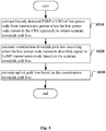
- Fig. 4 shows a method for path compensation of uplink power control according to an embodiment of the disclosure.
- the method as shown in Fig. 4 is applicable for a case that the macro base station and the low power node perform CoMP transmission on at least a first component carrier and the low power node further communicates with the user equipment via at least a second component carrier.
- a coordination downlink path loss when the low power node performs the CoMP transmission for the user equipment on the first component carrier is estimated with reference to a separate downlink path loss occurred when the low power node transmits a downlink signal separately for the user equipment on the second component carrier.
- the separate downlink path loss may be obtained according to the transmission power when the low power node transmits a CRS (Cell-Specific Reference Signal) separately and linearly detected RSRP (Reference Signal Receiving Power) of the CRS of the low power node.
- CRS Cell-Specific Reference Signal
- RSRP Reference Signal Receiving Power
- step S420 based on the coordination downlink path loss, an uplink path loss of an uplink signal issued by the user equipment which takes the low power node as a target receiving node on the first component carrier is estimated, to perform uplink signal transmission power compensation.
- Fig. 5 shows an example of a method for estimating an uplink path loss.
- linearly detected RSRP of a CRS of the low power node may be subtracted from transmission power when the low power node transmits the CRS separately, to obtain a separate downlink path loss.
- This may be expressed with the following expression (1).
- PL LPN dB TxPower LPN _ CRS dB ⁇ 10 ⁇ log 10 RSRP LPN Linear CRS
- a coordination downlink path loss f PL LPN dB occurring when the low power node transmits a downlink signal in a CoMP mode may be estimated based on the separate downlink path loss PL LPN dB .
- a deviation value between the separate downlink path loss PL LPN dB and the coordination downlink path loss f PL LPN dB is related to working frequency points of the two carriers, a frequency offset, a transmission environment of the low power node, a specific position of the terminal within the coverage area of the low power node and the like.
- an uplink path loss may be estimated based on the coordination downlink path loss f PL LPN dB , for example, according to the characteristic of reciprocity between an uplink channel and a downlink channel.
- the simplest treatment is that the uplink path loss is considered as being equal to the coordination downlink path loss f PL LPN dB .
- the uplink signal here may include a PUSCH signal, a PUCCH signal, or a SRS.
- the above expressions (2) to (4) are closed-loop power control formulas for the PUSCH, the PUCCH and the SRS, respectively.
- the derivation of the uplink power control adjustment parameters of an uplink signal which takes the low power node as the target receiving node has been described above.
- the derivation of the uplink power control adjustment parameters of an uplink signal may also be performed.
- a coordination downlink path loss when the macro base station performs the CoMP transmission for the user equipment on the first component carrier may be estimated based on the coordination downlink path loss of the low power node.
- the receiving power of the low power node may be obtained, for example, according to transmission power when the low power node transmits a CRS (Cell-Specific Reference Signal), data or a CSI-RS (Channel State Information-Reference Signal) in the CoMP transmission mode for the user equipment on the first component carrier and the coordination downlink path loss of the low power node.
- a CRS Cell-Specific Reference Signal
- CSI-RS Channel State Information-Reference Signal
- the receiving power of the macro base station may be obtained according to the linearly detected RSPS of the CRS of the low power node and the macro base station as well as the receiving power of the low power node.
- a coordination downlink path loss of the macro base station may be obtained according to the transmission power when the macro base station transmits the CRS in the CoMP transmission mode for the user equipment on the first component carrier and the receiving power of the macro base station.
- an uplink path loss of an uplink signal issued by the user equipment which takes the macro base station as the target receiving node on the first component carrier may be estimated, to perform uplink signal transmission power compensation.
- the uplink signal here may also include a PUSCH signal, a PUCCH signal or a SRS.
- a PUSCH signal a PUCCH signal
- a SRS a SRS
- an uplink path loss of the macro base station which is referred to as "an uplink path loss of the macro base station” hereinafter
- the expression (1) mentioned above may also be adopted.
- linearly detected RSRP of a CRS of the low power node 10 ⁇ log 10 RSRP LPN Linear CRS may be firstly subtracted from transmission power TxPower ( LPN_CRS ) dB when the low power node transmits the CRS separately, to obtain a separate downlink path loss PL LPN dB of the low power node.
- a coordination downlink path loss f PL LPN dB occurring when the low power node transmits a downlink signal in a CoMP transmission mode may be estimated based on the separate downlink path loss PL LPN dB .
- an uplink path loss of an uplink signal issued by the user equipment which takes the low power node as the target receiving node (which is referred to as "an uplink path loss of the low power node” hereinafter) may be further estimated based on the coordination downlink path loss f PL LPN dB of the low power node, for example, according to the characteristic of reciprocity between an uplink channel and a downlink channel.
- TxPower Macro _ CRS dB ⁇ PL macro dB + TxPower LPN _ CRS dB ⁇ f PL LPN dB 10 ⁇ log 10 RSRP macro + LPN Linear CRS
- the estimated coordination downlink path loss f PL LPN dB of the low power node may be firstly subtracted from transmission power TxPower ( LPN_CRS ) dB when the low power node transmits a CRS in the CoMP transmission mode, to obtain receiving power of the low power node.
- TxPower LPN_CRS
- the receiving power of the low power node may be subtracted from the linearly detected RSRP 10 ⁇ log 10 RSRP macro + LPN Linear ( CRS ) of the CRS of the low power node and the macro base station, to obtain receiving power of the macro base station.
- CRS LPN Linear
- the receiving power of the macro base station may be subtracted from transmission power TxPower ( Macro_CRS ) dB when the macro base station transmits the CRS in the CoMP transmission mode, to obtain a coordination downlink path loss PL macro dB of the macro base station.
- TxPower Macro_CRS
- an uplink path loss of the macro base station may be estimated based on the coordination downlink path loss PL macro dB of the macro base station according to the reciprocity between an uplink channel and a downlink channel.
- the path loss PL therein is replaced with PL macro dB , and then an uplink transmission power value of the PUSCH/PUCCH/SRS of the closed-loop power control and an uplink transmission power value of the open-loop power control may be derived.
- the estimated coordination downlink path loss f PL LPN dB of the low power node may be firstly subtracted from transmission power TxPower ( LPN_Data / LPN _ CSI ) dB when the low power node transmits a data signal or a CSI-RS in the CoMP transmission mode, to obtain receiving power of the low power node.
- the receiving power of the low power node may be subtracted from the linearly detected RSRP 10 ⁇ log 10 RSRP macro + LPN Linear CRS of the CRS of the low power node and the macro base station, to obtain receiving power of the macro base station.
- the receiving power of the macro base station may be subtracted from transmission power TxPower ( Macro_CRS ) dB when the macro base station transmits the CRS in the CoMP transmission mode, to obtain a coordination downlink path loss PL macro dB of the macro base station.
- TxPower Macro_CRS
- an uplink path loss of the macro base station may be estimated based on the coordination downlink path loss PL macro dB of the macro base station according to the reciprocity between an uplink channel and a downlink channel.
- the path loss PL therein is replaced with PL macro dB , and then an uplink transmission power value of the PUSCH/PUCCH/SRS of the closed-loop power control and an uplink transmission power value of the open-loop power control may be derived.
- TxPower Macro _ CRS dB ⁇ PL macro dB indicates the power that the macro base station transmits the CRS to a terminal (receiving power of the macro base station)
- TxPower LPN _ Data / LPN _ CSI dB ⁇ f PL LPN dB indicates the power that the low power node transmits the data signal or the CSI-RS to the terminal (receiving power of the low power node).
- the linearly detected RSRP 10 ⁇ log 10 RSRP macro + LPN Linear CRS of the CRS of the low power node and the macro base station may be obtained by adding the two power values described above.
- the receiving power of the macro base station and the receiving power of the low power node may offset each other, in addition to mutual superimposition.
- the estimated coordination downlink path loss f PL LPN dB of the low power node may also be firstly subtracted from transmission power TxPower ( LPN _ Data / LPN _ CSI ) dB when the low power node transmits a data signal or a CSI-RS in the CoMP transmission mode, to obtain receiving power of the low power node.
- linearly detected RSRP 10 ⁇ log 10 RSRP macro + LPN Linear CRS of the CRS of the low power node and the macro base station may be added the receiving power of the low power node, to obtain receiving power of the macro base station.
- the receiving power of the macro base station may be subtracted from transmission power TxPower ( Macro_CRS ) dB when the macro base station transmits the CRS in the CoMP transmission mode, to obtain a coordination downlink path loss PL macro dB of the macro base station.
- TxPower Macro_CRS
- an uplink path loss of the macro base station may be estimated based on the coordination downlink path loss PL macro dB of the macro base station according to the reciprocity between an uplink channel and a downlink channel.
- the path loss PL therein is replaced with PL macro dB , and then an uplink transmission power value of the PUSCH/PUCCH/SRS of the closed-loop power control and an uplink transmission power value of the open-loop power control may also be derived.
- the above expression (8) describes a case that the receiving power of the macro base station and the receiving power of the low power node offset each other and the receiving power of the macro base station is larger than the receiving power of the low power node.
- the estimated coordination downlink path loss f PL LPN dB of the low power node may also be firstly subtracted from transmission power TxPower ( LPN_Data / LPN _ CSI ) dB when the low power node transmits a data signal or a CSI-RS in the CoMP transmission mode, to obtain receiving power of the low power node.
- linearly detected RSRP 10 ⁇ log 10 RSRP macro + LPN Linear CRS of the CRS of the low power node and the macro base station may be subtracted from the receiving power of the low power node, to obtain receiving power of the macro base station.
- the receiving power of the macro base station may be subtracted from transmission power TxPower ( Macro_CRS ) dB when the macro base station transmits the CRS in the CoMP transmission mode, to obtain a coordination downlink path loss PL macro dB of the macro base station.
- TxPower Macro_CRS
- an uplink path loss of the macro base station may be estimated based on the coordination downlink path loss PL macro dB of the macro base station according to the reciprocity between an uplink channel and a downlink channel.
- the path loss PL therein is replaced with PL macro dB , and then an uplink transmission power value of the PUSCH/PUCCH/SRS of the closed-loop power control and an uplink transmission power value of the open-loop power control may also be derived.
- the uplink PUCCH/PUSCH transmission is transmitted on the aggregated carriers of the low power transmission node as far as possible.
- the path loss of the low power node on a multi-point transmission frequency band is predicted with reference to the path loss where the low power node separately transmits a carrier, thereby obtaining path loss compensation values of the uplink power control of a macro base station node and the low power node, to perform more accurate uplink power control.
- the wireless communication system 100 includes a macro base station 210, a low power node 220, and a wireless communication device 300.
- the low power node 220 and the macro base station 210 are in common baseband, and the wireless communication device 300 may communicate with the low power node 220 and the macro base station 210 via multiple component carriers.
- the wireless communication device 300 may include a receiving unit 310, a transmitting unit 320, a control unit 330 and the like.
- the receiving unit 310 may be used to receive a downlink signal transmitted by the low power node 220 and the macro base station 210.
- the transmitting unit 320 may be used to transmit uplink signals to the low power node 220 and the macro base station 210.
- the control unit 330 may be used to control the transmitting unit 320 to transmit all of first uplink signals of the uplink signals to the low power node 220 as a receiving node.
- the first uplink signals here may include PUCCH signal and/or PUSCH signal.
- Carrier aggregation may be performed between the low power node 220 and the macro base station 210, and the macro base station 210 may set a downlink component carrier thereof as a downlink primary component carrier.
- control unit 330 may release the association between an uplink primary component carrier and the downlink primary component carrier.
- control unit 330 may set an uplink component carrier of the low power node 220 as the uplink primary component carrier.
- the wireless communication system 100 may also be a TDD system.
- a transmission function of the downlink primary component carrier may be performed by a downlink timeslot of a component carrier of the macro base station 210
- a transmission function of the uplink primary component carrier may be performed by an uplink timeslot of a component carrier of the low power node 220.
- the macro base station 210 may inform the wireless communication device 300 of the uplink primary component carrier on the low power node 220 or recovery of the association between the uplink primary component carrier and the downlink primary component carrier via RRC signaling, MAC signaling or DCI of physical layer.
- the receiving unit 310 may receive the RRC signaling, the MAC signaling or the DCI of the physical layer, to know the uplink primary component carrier on the low power node 220.
- the control unit 330 may select by default a component carrier with highest or lowest frequency point from these component carriers as the uplink primary component carrier on the low power node 220.
- the receiving unit 310 may also receive the RRC signaling, the MAC signaling or the DCI of the physical layer, to know recovery of the association between the uplink primary component carrier and the downlink primary component carrier.
- the control unit 330 may also recover by default the association between the uplink primary component carrier and the downlink primary component carrier. After the association between the uplink primary component carrier and the downlink primary component carrier is recovered, an uplink component carrier of the macro base station 210 may be set as the uplink primary component carrier.
- the macro base station 210 and the low power node 220 may perform CoMP transmission on a first component carrier, and the low power node 220 may also communicate with the wireless communication device 300 via a second component carrier.
- the wireless communication device 300 may further include an estimating unit 340 to estimate an uplink path loss of an uplink signal issued by the wireless communication device 300 which takes the low power node 220 or the macro base station 210 as a target receiving node, thereby performing uplink signal transmission power compensation.
- the estimating unit 340 may be used to estimate a coordination downlink path loss when the low power node 220 performs the CoMP transmission for the wireless communication device 300 on the first component carrier, with reference to a separate downlink path loss occurring when the low power node 220 transmits a downlink signal separately for the wireless communication device 300 on the second component carrier. Then, based on the coordination downlink path loss of the low power node 220, the estimating unit 340 may also estimate an uplink path loss of an uplink signal issued by the wireless communication device 300 which takes the low power node 220 as the target receiving node, to perform the uplink signal transmission power compensation.
- the estimating unit 340 may be used to estimate a coordination downlink path loss when the macro base station 210 performs the CoMP transmission for the wireless communication device 300 on the first component carrier based on the coordination downlink path loss of the low power node 220. Then, based on the coordination downlink path loss of the macro base station 210, the estimating unit 340 may also estimate an uplink path loss of an uplink signal issued by the wireless communication device 300 which takes the macro base station 210 as a target receiving node, to perform the uplink signal transmission power compensation.
- each operation process of the method for performing wireless communication in a wireless communication system may be implemented with a computer executable program stored in various machine readable storage mediums.
- the object of the disclosure may be implemented in a way that: a storage medium storing the above executable program code is directly or indirectly provided to a system or an apparatus, and a computer or a CPU (Central Processing Unit) in the system or the apparatus reads and performs the above program code.
- a storage medium storing the above executable program code is directly or indirectly provided to a system or an apparatus, and a computer or a CPU (Central Processing Unit) in the system or the apparatus reads and performs the above program code.
- the embodiment of the disclosure is not limited to the program, and the program may be in any form, such as an object program, a program executed by an interpreter or a script program provided to an operating system.
- machine readable storage mediums described above include but not limited to various memories and memory cells, semiconductor apparatuses, disk units (such as an optical disk, a magnetic disk and a magneto-optical disk), and other mediums suitable for storing information.
- the technical solution of the disclosure may also be implemented by connecting a computer to a corresponding website on internet, loading and mounting a computer program code according to the disclosure into the computer, and then performing the program.
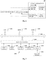
- Fig. 7 is a block diagram of an exemplary structure of a general-purpose personal computer in which a method for performing wireless communication in a wireless communication system according to an embodiment of the disclosure can be implemented.
- a CPU Central Processing Unit 1301 performs various processing in accordance with a program stored in a ROM (Read-Only Memory) 1302 or a program loaded from a storage section 1308 into a RAM (Random Access Memory) 1303.
- ROM Read-Only Memory
- RAM Random Access Memory
- data required when the CPU 1301 performs various processing is also stored as necessary.
- the CPU 1301, the ROM 1302 and the RAM 1303 are connected with each other via a bus 1304.
- An input/output interface 1305 is also connected to the bus 1304.
- the following components are connected to the input/output interface 1305: an input section 1306 (including a keyboard, a mouse and the like), an output section 1307 (including a display (such as a CRT (Cathode-Ray Tube) and a LCD (Liquid Crystal Display)), a speaker and the like), a storage section 1308 (including a hard disk and the like) and a communication section 1309 (including a network interface card such as a LAN (Local Area Network) card, a modem and the like).
- the communication section 1309 performs communication processing via a network such as internet.
- a driver 1310 may also be connected to the input/output interface 1305 as necessary.
- a removable medium 1311 such as a magnetic disk, an optical disk, a magneto-optical disk and a semiconductor memory, may be mounted onto the driver 1310 as necessary, so that a computer program read from the removable medium 1311 may be installed into the storage section 1308 as necessary.
- programs constituting the software may be installed from a network such as internet or a storage medium such as the removable medium 1311.
- the storage medium is not limited to the removable medium 1311 shown in Fig. 7 which stores a program therein and distributes the program separately from the apparatus to provide the program to a user.
- the removable medium 1311 include a magnetic disk (including a floppy disk (registered mark)), an optical disk (including a CD-ROM (Compact Disc Read Only Memory) and a DVD (Digital Versatile Disk)), a magneto-optical disk (including a MD (Mini Disk) (registered mark)) and a semiconductor memory.
- the storage medium may be a hard disk included in the ROM 1302 or the storage section 1308 and the like, which stores a program therein and is distributed to the user together with the apparatus in which the storage medium is included.
Landscapes
- Engineering & Computer Science (AREA)
- Signal Processing (AREA)
- Computer Networks & Wireless Communication (AREA)
- Mobile Radio Communication Systems (AREA)
Claims (10)
- Dispositif de communication (300) fonctionnant dans un système de communication (100) comprenant un premier nœud (210) et un second nœud (220), le dispositif de communication comprenant :des circuits configurés pour entraîner une communication avec le premier nœud et le second nœud sur la base d'une agrégation de porteuse, la communication incluant :l'établissement d'une porteuse de composante en liaison descendante associée au premier nœud en tant que porteuse de composante principale en liaison descendante, etl'établissement d'une porteuse de composante en liaison montante associée au second nœud en tant que porteuse de composante principale en liaison montante destinée à transmettre un canal de commande physique de liaison montante, PUCCH,dans lequel la communication inclut la transmission, au moyen des circuits, d'une signalisation de commande de liaison montante par le biais de la porteuse de composante principale en liaison montante associée au second nœud,dans lequel la communication inclut la réception depuis le second nœud, par les circuits, d'informations de désignation relatives à la porteuse de composante principale en liaison montante par le biais de l'une d'une signalisation de commande de ressource radio, RRC, d'une signalisation de contrôle d'accès au support, MAC, ou d'une signalisation de couche physique ; etdans lequel le premier nœud est une macro station de base et le second nœud est un nœud de faible puissance, LPN.
- Dispositif selon la revendication 1, dans lequel le premier nœud et le second nœud sont dans une bande de base commune.
- Dispositif selon la revendication 1, dans lequel la communication inclut, avant ledit établissement de la porteuse de composante en liaison montante, la libération de l'association de la porteuse de composante principale en liaison descendante de la porteuse de composante principale en liaison montante.
- Dispositif selon la revendication 1, dans lequel le premier nœud fonctionne à une première fréquence et le second nœud fonctionne à une seconde fréquence supérieure à la première fréquence.
- Dispositif selon la revendication 1, dans lequel la communication inclut la transmission, au moyen des circuits, de la signalisation de commande de liaison montante par le biais de la porteuse de composante principale en liaison montante associée au second nœud pour commander les transmissions entre le dispositif et le premier nœud.
- Dispositif selon la revendication 1, dans lequel la communication inclut l'agrégation de multiples porteuses de composante pour le second nœud.
- Dispositif selon la revendication 1, dans lequel la communication inclut la transmission, au moyen des circuits, de signaux de canal physique partagé de liaison montante, PUSCH, par le biais de la porteuse de composante principale en liaison montante associée au second nœud.
- Dispositif selon la revendication 1, dans lequel la communication inclut la transmission, au moyen des circuits, de toutes les signalisations de commande de liaison montante par le biais de la porteuse de composante principale en liaison montante associée au second nœud.
- Procédé de communication sans fil comprenant :l'exécution d'une communication, au moyen d'un processeur, avec un premier nœud (210) et un second nœud (220) sur la base d'une agrégation de porteuse, ladite communication incluant :l'établissement d'une porteuse de composante en liaison descendante associée au premier nœud en tant que porteuse de composante principale en liaison descendante, etl'établissement d'une porteuse de composante en liaison montante associée au second nœud en tant que porteuse de composante principale en liaison montante destinée à transmettre un canal de commande physique de liaison montante, PUCCH,dans lequel la communication inclut la transmission d'une signalisation de commande de liaison montante par le biais de la porteuse de composante principale en liaison montante associée au second nœud,dans lequel la communication inclut la réception, depuis le second nœud, d'informations de désignation relatives à la porteuse de composante principale en liaison montante par le biais de l'une d'une signalisation de commande de ressource radio, RRC, d'une signalisation de contrôle d'accès au support, MAC, ou d'une signalisation de couche physique ; etdans lequel le premier nœud est une macro station de base et le second nœud est un nœud de faible puissance, LPN.
- Procédé de communication sans fil selon la revendication 9, dans lequel la communication inclut la transmission d'une signalisation de commande de liaison montante par le biais de la porteuse de composante principale en liaison montante associée au second nœud pour commander les transmissions entre le processeur et le premier nœud.
Priority Applications (1)
| Application Number | Priority Date | Filing Date | Title |
|---|---|---|---|
| EP20162207.3A EP3697016A1 (fr) | 2013-05-28 | 2014-05-19 | Procédé, dispositif et système permettant d'effectuer une communication sans fil dans un système de communication sans fil |
Applications Claiming Priority (2)
| Application Number | Priority Date | Filing Date | Title |
|---|---|---|---|
| CN201310202975.8A CN104185261A (zh) | 2013-05-28 | 2013-05-28 | 用于在无线通信系统中进行无线通信的方法、装置和系统 |
| PCT/CN2014/077786 WO2014190859A1 (fr) | 2013-05-28 | 2014-05-19 | Procédé, dispositif et système permettant d'exécuter une communication sans fil dans un système de communication sans fil |
Related Child Applications (2)
| Application Number | Title | Priority Date | Filing Date |
|---|---|---|---|
| EP20162207.3A Division-Into EP3697016A1 (fr) | 2013-05-28 | 2014-05-19 | Procédé, dispositif et système permettant d'effectuer une communication sans fil dans un système de communication sans fil |
| EP20162207.3A Division EP3697016A1 (fr) | 2013-05-28 | 2014-05-19 | Procédé, dispositif et système permettant d'effectuer une communication sans fil dans un système de communication sans fil |
Publications (3)
| Publication Number | Publication Date |
|---|---|
| EP3005804A1 EP3005804A1 (fr) | 2016-04-13 |
| EP3005804A4 EP3005804A4 (fr) | 2017-05-10 |
| EP3005804B1 true EP3005804B1 (fr) | 2020-04-22 |
Family
ID=51965917
Family Applications (2)
| Application Number | Title | Priority Date | Filing Date |
|---|---|---|---|
| EP14804687.3A Active EP3005804B1 (fr) | 2013-05-28 | 2014-05-19 | Procédé, dispositif et système permettant d'exécuter une communication sans fil dans un système de communication sans fil |
| EP20162207.3A Withdrawn EP3697016A1 (fr) | 2013-05-28 | 2014-05-19 | Procédé, dispositif et système permettant d'effectuer une communication sans fil dans un système de communication sans fil |
Family Applications After (1)
| Application Number | Title | Priority Date | Filing Date |
|---|---|---|---|
| EP20162207.3A Withdrawn EP3697016A1 (fr) | 2013-05-28 | 2014-05-19 | Procédé, dispositif et système permettant d'effectuer une communication sans fil dans un système de communication sans fil |
Country Status (8)
| Country | Link |
|---|---|
| US (6) | US10492180B2 (fr) |
| EP (2) | EP3005804B1 (fr) |
| JP (1) | JP6226064B2 (fr) |
| KR (1) | KR102254938B1 (fr) |
| CN (2) | CN112218360A (fr) |
| BR (1) | BR112015029120B1 (fr) |
| CA (1) | CA2912118C (fr) |
| WO (1) | WO2014190859A1 (fr) |
Families Citing this family (14)
| Publication number | Priority date | Publication date | Assignee | Title |
|---|---|---|---|---|
| CN112218360A (zh) | 2013-05-28 | 2021-01-12 | 索尼公司 | 用于在无线通信系统中进行无线通信的方法、装置和系统 |
| CN105812109B (zh) * | 2014-12-31 | 2018-09-11 | 中兴通讯股份有限公司 | 数据传输方法及装置 |
| WO2017070947A1 (fr) * | 2015-10-30 | 2017-05-04 | 华为技术有限公司 | Procédé, appareil et système de planification coopérative |
| KR102232093B1 (ko) | 2016-01-08 | 2021-03-24 | 닛본 덴끼 가부시끼가이샤 | 무선국 시스템, 무선 단말, 및 이들의 방법 |
| WO2018064799A1 (fr) * | 2016-10-07 | 2018-04-12 | Qualcomm Incorporated | Attribution de puissance pour transmissions en liaison montante |
| IL267295B (en) * | 2016-12-13 | 2022-08-01 | Guangdong Oppo Mobile Telecommunications Corp Ltd | Method and device for satellite power control |
| CN108207023B (zh) * | 2016-12-18 | 2020-12-29 | 上海朗帛通信技术有限公司 | 一种用于窄带通信的ue、基站中的方法和装置 |
| WO2019101216A1 (fr) | 2017-11-27 | 2019-05-31 | Guangdong Oppo Mobile Telecommunications Corp., Ltd. | Procédé et appareil de commande de cellule secondaire |
| CN108901063B (zh) * | 2018-06-27 | 2021-05-28 | 京信通信系统(中国)有限公司 | 聚合载波的功率控制方法、装置、基站和存储介质 |
| CN110753375B (zh) * | 2018-07-23 | 2021-11-19 | 中国移动通信有限公司研究院 | 链路切换控制方法、终端及基站 |
| TWI674808B (zh) * | 2018-11-01 | 2019-10-11 | 財團法人資訊工業策進會 | 無線通訊系統及控制平面之管理之切換方法 |
| CN111934830B (zh) * | 2019-05-13 | 2022-12-27 | 华为技术有限公司 | 一种通信方法及设备 |
| BR112022008746A2 (pt) * | 2019-11-07 | 2022-08-16 | Zte Corp | Método de comunicação sem fio para determinar relação espacial e parâmetro de controle de potência para sinais de enlace ascendente |
| US11632271B1 (en) | 2022-02-24 | 2023-04-18 | T-Mobile Usa, Inc. | Location-based channel estimation in wireless communication systems |
Citations (2)
| Publication number | Priority date | Publication date | Assignee | Title |
|---|---|---|---|---|
| WO2010104957A2 (fr) * | 2009-03-12 | 2010-09-16 | Interdigital Patent Holdings, Inc. | Procédé et appareil pour sélectionner et resélectionner une porteuse primaire de liaison montante |
| WO2012149661A1 (fr) * | 2011-04-30 | 2012-11-08 | Nokia Siemens Networks Oy | Procédé et appareil |
Family Cites Families (30)
| Publication number | Priority date | Publication date | Assignee | Title |
|---|---|---|---|---|
| US9084206B2 (en) * | 2009-06-23 | 2015-07-14 | Samsung Electronics Co., Ltd | Method and apparatus for controlling uplink transmission power in wireless communication system |
| WO2011021830A2 (fr) * | 2009-08-17 | 2011-02-24 | 엘지전자 주식회사 | Procédé et appareil d'allocation d'une porteuse de liaison montante pour transmettre des informations de contrôle de liaison montante dans un système de communication sans fil |
| CN102076062B (zh) * | 2009-11-20 | 2015-03-11 | 华为技术有限公司 | 上行发送功率控制参数的获取方法、基站和用户设备 |
| US20110267948A1 (en) * | 2010-05-03 | 2011-11-03 | Koc Ali T | Techniques for communicating and managing congestion in a wireless network |
| US10187859B2 (en) * | 2011-02-14 | 2019-01-22 | Qualcomm Incorporated | Power control and user multiplexing for heterogeneous network coordinated multipoint operations |
| US10455554B2 (en) | 2011-06-01 | 2019-10-22 | Nokia Solutions And Networks Oy | Signalling arrangement for inter-site carrier aggregation having only single component carrier available in uplink direction |
| JP2013034111A (ja) * | 2011-08-02 | 2013-02-14 | Sharp Corp | 基地局、端末、通信システムおよび通信方法 |
| JP5927801B2 (ja) * | 2011-08-02 | 2016-06-01 | シャープ株式会社 | 基地局、端末および通信方法 |
| KR20130018051A (ko) * | 2011-08-12 | 2013-02-20 | 주식회사 팬택 | 무선 통신 시스템에서 상향링크 전송 전력을 제어하는 장치 및 방법 |
| CN102958144B (zh) * | 2011-08-16 | 2016-08-10 | 上海贝尔股份有限公司 | 功率控制的方法和相应装置 |
| US9369971B2 (en) * | 2011-09-28 | 2016-06-14 | Sharp Kabushiki Kaisha | Mobile station device, communication system, communication method, and integrated circuit |
| CN103037490B (zh) * | 2011-09-30 | 2016-06-08 | 上海贝尔股份有限公司 | 上行链路控制信道功率控制的方法和相应装置 |
| US8948111B2 (en) * | 2011-10-03 | 2015-02-03 | Qualcomm Incorporated | Uplink resource management under coordinated multipoint transmission |
| JP5990815B2 (ja) * | 2011-11-07 | 2016-09-14 | シャープ株式会社 | 基地局、端末、通信システムおよび通信方法 |
| WO2013077782A1 (fr) * | 2011-11-21 | 2013-05-30 | Telefonaktiebolaget L M Ericsson (Publ) | Système de télécommunications amélioré, station de base, équipement utilisateur et procédé permettant de garantir des connexions de grande qualité |
| US9270346B2 (en) * | 2011-12-02 | 2016-02-23 | Apple Inc. | Methods for operating wireless electronic devices in coordinated multipoint transmission networks |
| US8885569B2 (en) * | 2011-12-19 | 2014-11-11 | Ofinno Technologies, Llc | Beamforming signaling in a wireless network |
| EP2789198B1 (fr) * | 2012-01-02 | 2016-12-21 | Huawei Technologies Co., Ltd. | Commande de puissance dans un système de communication sans fil pour des transmissions en liaison montante avec réception coordonnée |
| EP2813023A1 (fr) * | 2012-02-10 | 2014-12-17 | Nokia Solutions and Networks Oy | Agrégation de porteuses inter-sites |
| KR102102648B1 (ko) * | 2012-02-27 | 2020-04-21 | 엘지전자 주식회사 | 무선 통신 시스템에서 상향링크 송신 전력을 제어하는 방법 및 이를 위한 장치 |
| KR102040622B1 (ko) * | 2012-04-15 | 2019-11-05 | 엘지전자 주식회사 | 상향링크 자원 결정 방법 및 이를 이용한 상향링크 제어 신호 전송 방법, 그리고 이들을 위한 장치 |
| US9265036B2 (en) * | 2012-05-11 | 2016-02-16 | Telefonaktiebolaget L M Ericsson (Publ) | Selection of uplink control transmission format parameters based on content of the uplink control transmission |
| KR101647868B1 (ko) * | 2012-06-11 | 2016-08-11 | 주식회사 케이티 | 상향링크 채널과, 상향링크 채널에 연계된 상향링크 사운딩 참조신호 전송방법 및 그 단말 |
| US9210619B2 (en) * | 2012-06-20 | 2015-12-08 | Ofinno Technologies, Llc | Signalling mechanisms for wireless device handover |
| CN104737471B (zh) * | 2012-09-20 | 2018-06-05 | Lg电子株式会社 | 在无线通信系统中执行上行链路传输的方法和设备 |
| CN110087332B (zh) * | 2012-10-05 | 2024-02-02 | 日本电气株式会社 | 基站、用户设备及其通信方法 |
| US9622170B2 (en) * | 2012-11-02 | 2017-04-11 | Blackberry Limited | Wireless communication in heterogeneous networks |
| US20150358838A1 (en) * | 2013-01-10 | 2015-12-10 | Na Wei | Buffer status reporting for dual connection |
| US9723556B2 (en) * | 2013-04-24 | 2017-08-01 | Telefonaktiebolaget Lm Ericsson (Publ) | DRX method with TDM limitation and user equipment using the same |
| CN112218360A (zh) | 2013-05-28 | 2021-01-12 | 索尼公司 | 用于在无线通信系统中进行无线通信的方法、装置和系统 |
-
2013
- 2013-05-28 CN CN202010966447.XA patent/CN112218360A/zh active Pending
- 2013-05-28 CN CN201310202975.8A patent/CN104185261A/zh active Pending
-
2014
- 2014-05-19 JP JP2016515624A patent/JP6226064B2/ja active Active
- 2014-05-19 EP EP14804687.3A patent/EP3005804B1/fr active Active
- 2014-05-19 US US14/786,041 patent/US10492180B2/en not_active Expired - Fee Related
- 2014-05-19 EP EP20162207.3A patent/EP3697016A1/fr not_active Withdrawn
- 2014-05-19 WO PCT/CN2014/077786 patent/WO2014190859A1/fr active Application Filing
- 2014-05-19 KR KR1020157034582A patent/KR102254938B1/ko active IP Right Grant
- 2014-05-19 CA CA2912118A patent/CA2912118C/fr active Active
- 2014-05-19 BR BR112015029120-1A patent/BR112015029120B1/pt active IP Right Grant
-
2017
- 2017-04-07 US US15/481,832 patent/US10314017B2/en active Active
-
2019
- 2019-04-23 US US16/391,320 patent/US10820306B2/en active Active
-
2020
- 2020-09-29 US US17/035,789 patent/US11425698B2/en active Active
-
2022
- 2022-04-08 US US17/715,952 patent/US20220232560A1/en not_active Abandoned
-
2023
- 2023-10-05 US US18/376,942 patent/US20240049236A1/en active Pending
Patent Citations (2)
| Publication number | Priority date | Publication date | Assignee | Title |
|---|---|---|---|---|
| WO2010104957A2 (fr) * | 2009-03-12 | 2010-09-16 | Interdigital Patent Holdings, Inc. | Procédé et appareil pour sélectionner et resélectionner une porteuse primaire de liaison montante |
| WO2012149661A1 (fr) * | 2011-04-30 | 2012-11-08 | Nokia Siemens Networks Oy | Procédé et appareil |
Also Published As
| Publication number | Publication date |
|---|---|
| US10314017B2 (en) | 2019-06-04 |
| EP3005804A4 (fr) | 2017-05-10 |
| US10492180B2 (en) | 2019-11-26 |
| CN104185261A (zh) | 2014-12-03 |
| BR112015029120A2 (pt) | 2017-07-25 |
| US20220232560A1 (en) | 2022-07-21 |
| CA2912118A1 (fr) | 2014-12-04 |
| US20160081078A1 (en) | 2016-03-17 |
| KR20160015241A (ko) | 2016-02-12 |
| WO2014190859A1 (fr) | 2014-12-04 |
| JP2016524404A (ja) | 2016-08-12 |
| EP3697016A1 (fr) | 2020-08-19 |
| US20210014856A1 (en) | 2021-01-14 |
| US20240049236A1 (en) | 2024-02-08 |
| KR102254938B1 (ko) | 2021-05-25 |
| CN112218360A (zh) | 2021-01-12 |
| US10820306B2 (en) | 2020-10-27 |
| US20170223696A1 (en) | 2017-08-03 |
| EP3005804A1 (fr) | 2016-04-13 |
| CA2912118C (fr) | 2023-02-28 |
| BR112015029120B1 (pt) | 2023-01-10 |
| US11425698B2 (en) | 2022-08-23 |
| JP6226064B2 (ja) | 2017-11-08 |
| US20190254023A1 (en) | 2019-08-15 |
Similar Documents
| Publication | Publication Date | Title |
|---|---|---|
| US11425698B2 (en) | Method, device and system for performing wireless communication in wireless communication system | |
| EP3070983B1 (fr) | Procédé et disposition pour la gestion d'une commande de puissance | |
| EP3029875B1 (fr) | Procédé et dispositif de réduction du brouillage | |
| EP2923510B1 (fr) | Procédés et noeud de réseau radio permettant de mesurer des interférences | |
| US10595279B2 (en) | Power control method and device | |
| KR20190025972A (ko) | 업링크 전송 파워 제어의 방법, 장치, 기기 및 저장 매체 | |
| US20170311320A1 (en) | Control data signaling framework for lte-laa communication systems employing carrier aggregation on unlicensed bands | |
| EP2744277A1 (fr) | Procédé et dispositif de régulation de la puissance sur la liaison montante | |
| EP3582535B1 (fr) | Procédé pour indiquer une capacité de station de base et appareil | |
| US20130143614A1 (en) | Method for controlling uplink transmit power in mobile communication system | |
| US20200374903A1 (en) | Power control method and communications apparatus | |
| EP2635075A1 (fr) | Système de communication mobile, station de base et procédé de commande de puissance d'émission | |
| WO2020030159A1 (fr) | Procédé et appareil de régulation de puissance, dispositif de réception, et support de stockage | |
| CN104080117A (zh) | 用于LTE系统的small cell状态检测方法 | |
| EP3439375A1 (fr) | Terminal utilisateur, station de base sans fil et procédé de communication sans fil | |
| JP6174564B2 (ja) | 送信装置、受信装置及び送信電力制御方法 | |
| US9756577B2 (en) | Method for defining parameter values for controlling the transmission power of a piece of user equipment | |
| US20220312229A1 (en) | Methods and devices for wireless communication | |
| US20130102355A1 (en) | Radio base station and power control method | |
| CN118451770A (zh) | 功率余量报告(phr)报告的方法及设备 |
Legal Events
| Date | Code | Title | Description |
|---|---|---|---|
| PUAI | Public reference made under article 153(3) epc to a published international application that has entered the european phase |
Free format text: ORIGINAL CODE: 0009012 |
|
| 17P | Request for examination filed |
Effective date: 20151207 |
|
| AK | Designated contracting states |
Kind code of ref document: A1 Designated state(s): AL AT BE BG CH CY CZ DE DK EE ES FI FR GB GR HR HU IE IS IT LI LT LU LV MC MK MT NL NO PL PT RO RS SE SI SK SM TR |
|
| AX | Request for extension of the european patent |
Extension state: BA ME |
|
| DAX | Request for extension of the european patent (deleted) | ||
| RIC1 | Information provided on ipc code assigned before grant |
Ipc: H04W 72/04 20090101ALI20161221BHEP Ipc: H04W 52/24 20090101ALI20161221BHEP Ipc: H04W 72/00 20090101ALI20161221BHEP Ipc: H04W 52/14 20090101ALI20161221BHEP Ipc: H04L 5/00 20060101AFI20161221BHEP |
|
| REG | Reference to a national code |
Ref country code: DE Ref legal event code: R079 Ref document number: 602014064209 Country of ref document: DE Free format text: PREVIOUS MAIN CLASS: H04W0072000000 Ipc: H04L0005000000 |
|
| A4 | Supplementary search report drawn up and despatched |
Effective date: 20170406 |
|
| RIC1 | Information provided on ipc code assigned before grant |
Ipc: H04W 72/04 20090101ALI20170401BHEP Ipc: H04W 52/24 20090101ALI20170401BHEP Ipc: H04L 5/00 20060101AFI20170401BHEP Ipc: H04W 72/00 20090101ALI20170401BHEP Ipc: H04W 52/14 20090101ALI20170401BHEP |
|
| STAA | Information on the status of an ep patent application or granted ep patent |
Free format text: STATUS: EXAMINATION IS IN PROGRESS |
|
| 17Q | First examination report despatched |
Effective date: 20180119 |
|
| GRAP | Despatch of communication of intention to grant a patent |
Free format text: ORIGINAL CODE: EPIDOSNIGR1 |
|
| STAA | Information on the status of an ep patent application or granted ep patent |
Free format text: STATUS: GRANT OF PATENT IS INTENDED |
|
| INTG | Intention to grant announced |
Effective date: 20191115 |
|
| INTG | Intention to grant announced |
Effective date: 20191119 |
|
| GRAS | Grant fee paid |
Free format text: ORIGINAL CODE: EPIDOSNIGR3 |
|
| GRAA | (expected) grant |
Free format text: ORIGINAL CODE: 0009210 |
|
| STAA | Information on the status of an ep patent application or granted ep patent |
Free format text: STATUS: THE PATENT HAS BEEN GRANTED |
|
| AK | Designated contracting states |
Kind code of ref document: B1 Designated state(s): AL AT BE BG CH CY CZ DE DK EE ES FI FR GB GR HR HU IE IS IT LI LT LU LV MC MK MT NL NO PL PT RO RS SE SI SK SM TR |
|
| REG | Reference to a national code |
Ref country code: CH Ref legal event code: EP |
|
| REG | Reference to a national code |
Ref country code: IE Ref legal event code: FG4D |
|
| REG | Reference to a national code |
Ref country code: DE Ref legal event code: R096 Ref document number: 602014064209 Country of ref document: DE |
|
| REG | Reference to a national code |
Ref country code: AT Ref legal event code: REF Ref document number: 1261555 Country of ref document: AT Kind code of ref document: T Effective date: 20200515 |
|
| REG | Reference to a national code |
Ref country code: NL Ref legal event code: FP |
|
| REG | Reference to a national code |
Ref country code: LT Ref legal event code: MG4D |
|
| PG25 | Lapsed in a contracting state [announced via postgrant information from national office to epo] |
Ref country code: PT Free format text: LAPSE BECAUSE OF FAILURE TO SUBMIT A TRANSLATION OF THE DESCRIPTION OR TO PAY THE FEE WITHIN THE PRESCRIBED TIME-LIMIT Effective date: 20200824 Ref country code: SE Free format text: LAPSE BECAUSE OF FAILURE TO SUBMIT A TRANSLATION OF THE DESCRIPTION OR TO PAY THE FEE WITHIN THE PRESCRIBED TIME-LIMIT Effective date: 20200422 Ref country code: GR Free format text: LAPSE BECAUSE OF FAILURE TO SUBMIT A TRANSLATION OF THE DESCRIPTION OR TO PAY THE FEE WITHIN THE PRESCRIBED TIME-LIMIT Effective date: 20200723 Ref country code: LT Free format text: LAPSE BECAUSE OF FAILURE TO SUBMIT A TRANSLATION OF THE DESCRIPTION OR TO PAY THE FEE WITHIN THE PRESCRIBED TIME-LIMIT Effective date: 20200422 Ref country code: IS Free format text: LAPSE BECAUSE OF FAILURE TO SUBMIT A TRANSLATION OF THE DESCRIPTION OR TO PAY THE FEE WITHIN THE PRESCRIBED TIME-LIMIT Effective date: 20200822 Ref country code: NO Free format text: LAPSE BECAUSE OF FAILURE TO SUBMIT A TRANSLATION OF THE DESCRIPTION OR TO PAY THE FEE WITHIN THE PRESCRIBED TIME-LIMIT Effective date: 20200722 Ref country code: FI Free format text: LAPSE BECAUSE OF FAILURE TO SUBMIT A TRANSLATION OF THE DESCRIPTION OR TO PAY THE FEE WITHIN THE PRESCRIBED TIME-LIMIT Effective date: 20200422 |
|
| REG | Reference to a national code |
Ref country code: AT Ref legal event code: MK05 Ref document number: 1261555 Country of ref document: AT Kind code of ref document: T Effective date: 20200422 |
|
| PG25 | Lapsed in a contracting state [announced via postgrant information from national office to epo] |
Ref country code: LV Free format text: LAPSE BECAUSE OF FAILURE TO SUBMIT A TRANSLATION OF THE DESCRIPTION OR TO PAY THE FEE WITHIN THE PRESCRIBED TIME-LIMIT Effective date: 20200422 Ref country code: HR Free format text: LAPSE BECAUSE OF FAILURE TO SUBMIT A TRANSLATION OF THE DESCRIPTION OR TO PAY THE FEE WITHIN THE PRESCRIBED TIME-LIMIT Effective date: 20200422 Ref country code: BG Free format text: LAPSE BECAUSE OF FAILURE TO SUBMIT A TRANSLATION OF THE DESCRIPTION OR TO PAY THE FEE WITHIN THE PRESCRIBED TIME-LIMIT Effective date: 20200722 Ref country code: RS Free format text: LAPSE BECAUSE OF FAILURE TO SUBMIT A TRANSLATION OF THE DESCRIPTION OR TO PAY THE FEE WITHIN THE PRESCRIBED TIME-LIMIT Effective date: 20200422 |
|
| PG25 | Lapsed in a contracting state [announced via postgrant information from national office to epo] |
Ref country code: AL Free format text: LAPSE BECAUSE OF FAILURE TO SUBMIT A TRANSLATION OF THE DESCRIPTION OR TO PAY THE FEE WITHIN THE PRESCRIBED TIME-LIMIT Effective date: 20200422 |
|
| REG | Reference to a national code |
Ref country code: DE Ref legal event code: R097 Ref document number: 602014064209 Country of ref document: DE |
|
| PG25 | Lapsed in a contracting state [announced via postgrant information from national office to epo] |
Ref country code: CZ Free format text: LAPSE BECAUSE OF FAILURE TO SUBMIT A TRANSLATION OF THE DESCRIPTION OR TO PAY THE FEE WITHIN THE PRESCRIBED TIME-LIMIT Effective date: 20200422 Ref country code: RO Free format text: LAPSE BECAUSE OF FAILURE TO SUBMIT A TRANSLATION OF THE DESCRIPTION OR TO PAY THE FEE WITHIN THE PRESCRIBED TIME-LIMIT Effective date: 20200422 Ref country code: MC Free format text: LAPSE BECAUSE OF FAILURE TO SUBMIT A TRANSLATION OF THE DESCRIPTION OR TO PAY THE FEE WITHIN THE PRESCRIBED TIME-LIMIT Effective date: 20200422 Ref country code: ES Free format text: LAPSE BECAUSE OF FAILURE TO SUBMIT A TRANSLATION OF THE DESCRIPTION OR TO PAY THE FEE WITHIN THE PRESCRIBED TIME-LIMIT Effective date: 20200422 Ref country code: EE Free format text: LAPSE BECAUSE OF FAILURE TO SUBMIT A TRANSLATION OF THE DESCRIPTION OR TO PAY THE FEE WITHIN THE PRESCRIBED TIME-LIMIT Effective date: 20200422 Ref country code: AT Free format text: LAPSE BECAUSE OF FAILURE TO SUBMIT A TRANSLATION OF THE DESCRIPTION OR TO PAY THE FEE WITHIN THE PRESCRIBED TIME-LIMIT Effective date: 20200422 Ref country code: CH Free format text: LAPSE BECAUSE OF NON-PAYMENT OF DUE FEES Effective date: 20200531 Ref country code: SM Free format text: LAPSE BECAUSE OF FAILURE TO SUBMIT A TRANSLATION OF THE DESCRIPTION OR TO PAY THE FEE WITHIN THE PRESCRIBED TIME-LIMIT Effective date: 20200422 Ref country code: LI Free format text: LAPSE BECAUSE OF NON-PAYMENT OF DUE FEES Effective date: 20200531 Ref country code: IT Free format text: LAPSE BECAUSE OF FAILURE TO SUBMIT A TRANSLATION OF THE DESCRIPTION OR TO PAY THE FEE WITHIN THE PRESCRIBED TIME-LIMIT Effective date: 20200422 Ref country code: DK Free format text: LAPSE BECAUSE OF FAILURE TO SUBMIT A TRANSLATION OF THE DESCRIPTION OR TO PAY THE FEE WITHIN THE PRESCRIBED TIME-LIMIT Effective date: 20200422 |
|
| PG25 | Lapsed in a contracting state [announced via postgrant information from national office to epo] |
Ref country code: SK Free format text: LAPSE BECAUSE OF FAILURE TO SUBMIT A TRANSLATION OF THE DESCRIPTION OR TO PAY THE FEE WITHIN THE PRESCRIBED TIME-LIMIT Effective date: 20200422 Ref country code: PL Free format text: LAPSE BECAUSE OF FAILURE TO SUBMIT A TRANSLATION OF THE DESCRIPTION OR TO PAY THE FEE WITHIN THE PRESCRIBED TIME-LIMIT Effective date: 20200422 |
|
| PLBE | No opposition filed within time limit |
Free format text: ORIGINAL CODE: 0009261 |
|
| STAA | Information on the status of an ep patent application or granted ep patent |
Free format text: STATUS: NO OPPOSITION FILED WITHIN TIME LIMIT |
|
| REG | Reference to a national code |
Ref country code: BE Ref legal event code: MM Effective date: 20200531 |
|
| 26N | No opposition filed |
Effective date: 20210125 |
|
| GBPC | Gb: european patent ceased through non-payment of renewal fee |
Effective date: 20200722 |
|
| PG25 | Lapsed in a contracting state [announced via postgrant information from national office to epo] |
Ref country code: LU Free format text: LAPSE BECAUSE OF NON-PAYMENT OF DUE FEES Effective date: 20200519 |
|
| PG25 | Lapsed in a contracting state [announced via postgrant information from national office to epo] |
Ref country code: GB Free format text: LAPSE BECAUSE OF NON-PAYMENT OF DUE FEES Effective date: 20200722 Ref country code: IE Free format text: LAPSE BECAUSE OF NON-PAYMENT OF DUE FEES Effective date: 20200519 |
|
| PG25 | Lapsed in a contracting state [announced via postgrant information from national office to epo] |
Ref country code: BE Free format text: LAPSE BECAUSE OF NON-PAYMENT OF DUE FEES Effective date: 20200531 Ref country code: SI Free format text: LAPSE BECAUSE OF FAILURE TO SUBMIT A TRANSLATION OF THE DESCRIPTION OR TO PAY THE FEE WITHIN THE PRESCRIBED TIME-LIMIT Effective date: 20200422 |
|
| PG25 | Lapsed in a contracting state [announced via postgrant information from national office to epo] |
Ref country code: TR Free format text: LAPSE BECAUSE OF FAILURE TO SUBMIT A TRANSLATION OF THE DESCRIPTION OR TO PAY THE FEE WITHIN THE PRESCRIBED TIME-LIMIT Effective date: 20200422 Ref country code: MT Free format text: LAPSE BECAUSE OF FAILURE TO SUBMIT A TRANSLATION OF THE DESCRIPTION OR TO PAY THE FEE WITHIN THE PRESCRIBED TIME-LIMIT Effective date: 20200422 Ref country code: CY Free format text: LAPSE BECAUSE OF FAILURE TO SUBMIT A TRANSLATION OF THE DESCRIPTION OR TO PAY THE FEE WITHIN THE PRESCRIBED TIME-LIMIT Effective date: 20200422 |
|
| PG25 | Lapsed in a contracting state [announced via postgrant information from national office to epo] |
Ref country code: MK Free format text: LAPSE BECAUSE OF FAILURE TO SUBMIT A TRANSLATION OF THE DESCRIPTION OR TO PAY THE FEE WITHIN THE PRESCRIBED TIME-LIMIT Effective date: 20200422 |
|
| PGFP | Annual fee paid to national office [announced via postgrant information from national office to epo] |
Ref country code: NL Payment date: 20230419 Year of fee payment: 10 |
|
| P01 | Opt-out of the competence of the unified patent court (upc) registered |
Effective date: 20230527 |
|
| PGFP | Annual fee paid to national office [announced via postgrant information from national office to epo] |
Ref country code: DE Payment date: 20240418 Year of fee payment: 11 |
|
| PGFP | Annual fee paid to national office [announced via postgrant information from national office to epo] |
Ref country code: FR Payment date: 20240418 Year of fee payment: 11 |