EP3005447B1 - Intrinsic overcharge protection for battery cell - Google Patents
Intrinsic overcharge protection for battery cell Download PDFInfo
- Publication number
- EP3005447B1 EP3005447B1 EP14804024.9A EP14804024A EP3005447B1 EP 3005447 B1 EP3005447 B1 EP 3005447B1 EP 14804024 A EP14804024 A EP 14804024A EP 3005447 B1 EP3005447 B1 EP 3005447B1
- Authority
- EP
- European Patent Office
- Prior art keywords
- battery cell
- doped
- ion conducting
- conducting
- polymer film
- Prior art date
- Legal status (The legal status is an assumption and is not a legal conclusion. Google has not performed a legal analysis and makes no representation as to the accuracy of the status listed.)
- Active
Links
Images

Classifications
-
- H—ELECTRICITY
- H01—ELECTRIC ELEMENTS
- H01M—PROCESSES OR MEANS, e.g. BATTERIES, FOR THE DIRECT CONVERSION OF CHEMICAL ENERGY INTO ELECTRICAL ENERGY
- H01M10/00—Secondary cells; Manufacture thereof
- H01M10/42—Methods or arrangements for servicing or maintenance of secondary cells or secondary half-cells
- H01M10/4235—Safety or regulating additives or arrangements in electrodes, separators or electrolyte
-
- H—ELECTRICITY
- H01—ELECTRIC ELEMENTS
- H01M—PROCESSES OR MEANS, e.g. BATTERIES, FOR THE DIRECT CONVERSION OF CHEMICAL ENERGY INTO ELECTRICAL ENERGY
- H01M10/00—Secondary cells; Manufacture thereof
- H01M10/05—Accumulators with non-aqueous electrolyte
- H01M10/052—Li-accumulators
-
- H—ELECTRICITY
- H01—ELECTRIC ELEMENTS
- H01M—PROCESSES OR MEANS, e.g. BATTERIES, FOR THE DIRECT CONVERSION OF CHEMICAL ENERGY INTO ELECTRICAL ENERGY
- H01M10/00—Secondary cells; Manufacture thereof
- H01M10/05—Accumulators with non-aqueous electrolyte
- H01M10/052—Li-accumulators
- H01M10/0525—Rocking-chair batteries, i.e. batteries with lithium insertion or intercalation in both electrodes; Lithium-ion batteries
-
- H—ELECTRICITY
- H01—ELECTRIC ELEMENTS
- H01M—PROCESSES OR MEANS, e.g. BATTERIES, FOR THE DIRECT CONVERSION OF CHEMICAL ENERGY INTO ELECTRICAL ENERGY
- H01M10/00—Secondary cells; Manufacture thereof
- H01M10/05—Accumulators with non-aqueous electrolyte
- H01M10/056—Accumulators with non-aqueous electrolyte characterised by the materials used as electrolytes, e.g. mixed inorganic/organic electrolytes
- H01M10/0564—Accumulators with non-aqueous electrolyte characterised by the materials used as electrolytes, e.g. mixed inorganic/organic electrolytes the electrolyte being constituted of organic materials only
- H01M10/0565—Polymeric materials, e.g. gel-type or solid-type
-
- H—ELECTRICITY
- H01—ELECTRIC ELEMENTS
- H01M—PROCESSES OR MEANS, e.g. BATTERIES, FOR THE DIRECT CONVERSION OF CHEMICAL ENERGY INTO ELECTRICAL ENERGY
- H01M10/00—Secondary cells; Manufacture thereof
- H01M10/05—Accumulators with non-aqueous electrolyte
- H01M10/058—Construction or manufacture
- H01M10/0585—Construction or manufacture of accumulators having only flat construction elements, i.e. flat positive electrodes, flat negative electrodes and flat separators
-
- H—ELECTRICITY
- H01—ELECTRIC ELEMENTS
- H01M—PROCESSES OR MEANS, e.g. BATTERIES, FOR THE DIRECT CONVERSION OF CHEMICAL ENERGY INTO ELECTRICAL ENERGY
- H01M10/00—Secondary cells; Manufacture thereof
- H01M10/42—Methods or arrangements for servicing or maintenance of secondary cells or secondary half-cells
- H01M10/425—Structural combination with electronic components, e.g. electronic circuits integrated to the outside of the casing
- H01M10/4257—Smart batteries, e.g. electronic circuits inside the housing of the cells or batteries
-
- H—ELECTRICITY
- H01—ELECTRIC ELEMENTS
- H01M—PROCESSES OR MEANS, e.g. BATTERIES, FOR THE DIRECT CONVERSION OF CHEMICAL ENERGY INTO ELECTRICAL ENERGY
- H01M10/00—Secondary cells; Manufacture thereof
- H01M10/42—Methods or arrangements for servicing or maintenance of secondary cells or secondary half-cells
- H01M10/44—Methods for charging or discharging
-
- H—ELECTRICITY
- H01—ELECTRIC ELEMENTS
- H01M—PROCESSES OR MEANS, e.g. BATTERIES, FOR THE DIRECT CONVERSION OF CHEMICAL ENERGY INTO ELECTRICAL ENERGY
- H01M50/00—Constructional details or processes of manufacture of the non-active parts of electrochemical cells other than fuel cells, e.g. hybrid cells
- H01M50/40—Separators; Membranes; Diaphragms; Spacing elements inside cells
- H01M50/409—Separators, membranes or diaphragms characterised by the material
- H01M50/411—Organic material
-
- H—ELECTRICITY
- H01—ELECTRIC ELEMENTS
- H01M—PROCESSES OR MEANS, e.g. BATTERIES, FOR THE DIRECT CONVERSION OF CHEMICAL ENERGY INTO ELECTRICAL ENERGY
- H01M50/00—Constructional details or processes of manufacture of the non-active parts of electrochemical cells other than fuel cells, e.g. hybrid cells
- H01M50/40—Separators; Membranes; Diaphragms; Spacing elements inside cells
- H01M50/409—Separators, membranes or diaphragms characterised by the material
- H01M50/411—Organic material
- H01M50/414—Synthetic resins, e.g. thermoplastics or thermosetting resins
-
- H—ELECTRICITY
- H01—ELECTRIC ELEMENTS
- H01M—PROCESSES OR MEANS, e.g. BATTERIES, FOR THE DIRECT CONVERSION OF CHEMICAL ENERGY INTO ELECTRICAL ENERGY
- H01M2200/00—Safety devices for primary or secondary batteries
-
- H—ELECTRICITY
- H01—ELECTRIC ELEMENTS
- H01M—PROCESSES OR MEANS, e.g. BATTERIES, FOR THE DIRECT CONVERSION OF CHEMICAL ENERGY INTO ELECTRICAL ENERGY
- H01M2220/00—Batteries for particular applications
- H01M2220/20—Batteries in motive systems, e.g. vehicle, ship, plane
-
- Y—GENERAL TAGGING OF NEW TECHNOLOGICAL DEVELOPMENTS; GENERAL TAGGING OF CROSS-SECTIONAL TECHNOLOGIES SPANNING OVER SEVERAL SECTIONS OF THE IPC; TECHNICAL SUBJECTS COVERED BY FORMER USPC CROSS-REFERENCE ART COLLECTIONS [XRACs] AND DIGESTS
- Y02—TECHNOLOGIES OR APPLICATIONS FOR MITIGATION OR ADAPTATION AGAINST CLIMATE CHANGE
- Y02E—REDUCTION OF GREENHOUSE GAS [GHG] EMISSIONS, RELATED TO ENERGY GENERATION, TRANSMISSION OR DISTRIBUTION
- Y02E60/00—Enabling technologies; Technologies with a potential or indirect contribution to GHG emissions mitigation
- Y02E60/10—Energy storage using batteries
-
- Y—GENERAL TAGGING OF NEW TECHNOLOGICAL DEVELOPMENTS; GENERAL TAGGING OF CROSS-SECTIONAL TECHNOLOGIES SPANNING OVER SEVERAL SECTIONS OF THE IPC; TECHNICAL SUBJECTS COVERED BY FORMER USPC CROSS-REFERENCE ART COLLECTIONS [XRACs] AND DIGESTS
- Y02—TECHNOLOGIES OR APPLICATIONS FOR MITIGATION OR ADAPTATION AGAINST CLIMATE CHANGE
- Y02P—CLIMATE CHANGE MITIGATION TECHNOLOGIES IN THE PRODUCTION OR PROCESSING OF GOODS
- Y02P70/00—Climate change mitigation technologies in the production process for final industrial or consumer products
- Y02P70/50—Manufacturing or production processes characterised by the final manufactured product
-
- Y—GENERAL TAGGING OF NEW TECHNOLOGICAL DEVELOPMENTS; GENERAL TAGGING OF CROSS-SECTIONAL TECHNOLOGIES SPANNING OVER SEVERAL SECTIONS OF THE IPC; TECHNICAL SUBJECTS COVERED BY FORMER USPC CROSS-REFERENCE ART COLLECTIONS [XRACs] AND DIGESTS
- Y02—TECHNOLOGIES OR APPLICATIONS FOR MITIGATION OR ADAPTATION AGAINST CLIMATE CHANGE
- Y02T—CLIMATE CHANGE MITIGATION TECHNOLOGIES RELATED TO TRANSPORTATION
- Y02T10/00—Road transport of goods or passengers
- Y02T10/60—Other road transportation technologies with climate change mitigation effect
- Y02T10/70—Energy storage systems for electromobility, e.g. batteries
Definitions
- the present invention pertains to a battery cell according to the preamble to claim 1, and a battery according to claim 15.
- the present invention also pertains to a method for the manufacture of a battery cell according to the preamble to claim 17.
- Batteries are used today in a great number of devices, such as in vehicles, vessels, and in various electronic equipment, such as for example in computers, mobile telephones and toys. Generally, there are batteries in most electrical devices, which at least partly are designed so that they may be used without being connected to a power network. In this application, batteries are described primarily in their application for vehicles. However, they may of course also be used in other applications for vessels and various other electronic equipment which comprises batteries.
- a battery comprises one or several battery cells, which may have a number of different designs and comprise a number of different substances and/or chemical compounds.
- a battery/accumulator is drained when it is used and/or loses charging over time when it is not used.
- substantially reversible transformations of chemical compounds occur within the battery.
- the electrode materials comprised in the batteries may then be transformed from one chemical compound into another.
- the battery/accumulator may be charged again through an external voltage source, for example a generator in a vehicle or a vessel, or through a battery charger of some type, connected to the battery's poles.
- an external voltage source for example a generator in a vehicle or a vessel, or through a battery charger of some type, connected to the battery's poles.
- Batteries comprising organic electrolytes such as electrolytes comprising zinc ions, sodium ions and/or lithium ions, are sensitive to high temperatures and high cell voltages, which accelerate the ageing of the batteries. Additionally the electrolyte is very flammable. For example, temperatures exceeding around 55° C and/or cell voltages exceeding around 4.2 V may accelerate the ageing of a lithium ion battery. At higher cell voltages there is also a risk of gas development, degradation of the battery cells and/or fire in the battery cells.
- these discrete particles and/or components means that the power flow is concentrated at these discrete particles and/or components.
- concentrations of the power flow for example for positions at the respective particle or at the connection of a discrete overcharge component to the battery cell, creates heat at these concentrations.
- EP2551949 A1 discloses a lithium ion battery comprising a positive electrode and a negative electrode separated by a polymer electrolyte film.
- the polymer electrolyte film comprises a p-dopant or n-dopant complex agent providing an intrinsic over-charge/discharge protection.
- the objective is also achieved through the above mentioned method for the manufacture of a battery cell according to the characterising portion of claim 17.
- the battery cell according to the present invention comprises a positive and a negative electrode separated by at least one electrically conducting polymer film, which has an ion conducting electrolyte distributed within itself, a P-doped and electrically semi-conductive and ion conductive film, and an N-doped and electrically semi-conductive and ion conductive film.
- the battery cell has the following layers in the following order, which creates the intrinsic overcharge protection:
- an intrinsic/chemical overcharge protection is provided for the battery cell, which prevents too large charging voltages from being applied to the battery cell.
- the intrinsic/chemical overcharge protection provides a battery cell internal and automatic protection without the need for external voltage monitoring devices. This means that a degrading of the battery cell's capacity is counteracted without any added complexity and/or manufacturing cost for the device, for example a vehicle, in which the battery is used. In addition, the battery cell's function is not degraded by the overcharge protection being activated, since the overcharge protection is electrically active, and not electrochemically active.
- the concept with at least three layers that is to say the at least one polymer film and the P-doped and the N-doped films arranged in layers next to each other, have one advantage in that the P-doped and the N-doped films may be permitted to have a worse ion conducting ability than the ion conducting ability of the at least one polymer film.
- the at least one polymer film has a sufficient thickness to protect the battery cell from internal short-circuits during the life of the battery cell, the P-doped and the N-doped films may be made so thin that they do not significantly impact the battery cell's internal resistance.
- a lithium ion battery for example, becomes a simpler and an equally reliable alternative as the previously commonly used chargeable nickel-hybrid batteries.
- the overcharge protection may according to the present invention also provide an intrinsic active balancing function between the battery cells in the battery when charging. This facilitates a simplification of the balancing electronics, for example for hybrid vehicles and electric vehicles.
- the overcharge protection has according to one embodiment of the invention a characteristic similar to a Zener-diode. This means that the intrinsic overcharge protection may very quickly be activated to protect the battery cell, also in fast voltage sequences and during voltage transients.
- the intrinsic overcharging protection is homogeneously integrated in the battery cell, that is to say that the at least one polymer film has a homogeneous distribution of electrically conducting material and that the P-doped and N-doped films have a homogeneous distribution of electrically semi-conducting material.
- a battery cell is created with an even power distribution in the event of a short-circuit, where the voltage U over the battery cell is greater than the absolute amount for the created Zener-diode's breakdown voltage
- a very compact battery cell which comprises a reliable overcharge protection, and which is easy to manufacture, including in large numbers.
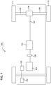
- FIG. 1 shows schematically an example vehicle 100, which may comprise the present invention.
- the vehicle 100 which may be a passenger car, a truck, a bus or another vehicle, comprises a drive line, which conveys power to driving wheels 110, 111 in the vehicle 100.
- the drive line comprises one engine 101, which in a customary manner, via an output shaft 102 on the engine 101, is connected to a gearbox 103 via a clutch 106.
- the engine 101 may for example be an electric engine, a hybrid engine or a combustion engine.
- the vehicle's drive line may be arranged in a great number of ways, such as comprising a conventional manual gearbox or an automatic transmission, and may be a hybrid drive line, etc.
- the vehicle comprises at least one battery 120. If the engine 101 is an electric engine, the battery 120 is used to at least partly drive the engine 101. If the engine 101 is a pure combustion engine which is driven by fuel, the battery 120 is used among others to drive a start engine in the engine 101, and to provide power to the engine's ignition system.
- the battery 120 also provides power to operate electric equipment 130 in the vehicle.
- This electric equipment 130 which is illustrated schematically in figure 1 , may comprise among others headlights and other lights, miscellaneous instruments, wipers, seat heaters, stereo equipment, video equipment, cigarette lighters and sockets for external equipment connected to the vehicle.
- An output shaft 107 from the gearbox 103 drives the wheels 110, 111 via a final drive 108, such as e.g. a customary differential, and drive shafts 104, 105 connected to said final drive 108.
- a final drive 108 such as e.g. a customary differential
- a battery cell 200 is provided, which is displayed schematically in Figure 2 .
- the battery cell 200 comprises a positive electrode 201 and a negative electrode 202, separated by at least one polymer film 203. According to the present invention, an intrinsic/chemical overcharge protection for the battery cell is provided, which prevents that the above described accelerated ageing occurs due to overcharging of the battery cell.
- the battery cell comprises a current feeder 206, which may consist of a number of materials, for example aluminium.
- One or several battery cells 200 may, according to the present invention, be comprised in a battery 120 according to the present invention, where the number of cells in the battery 120 depends on the voltage and/or power which the battery 120 is to provide.
- an intrinsic/chemical overcharge protection is achieved in the battery cell, which is described in more detail below.
- This intrinsic/chemical overcharge protection in the battery cell means that the battery cell, and thus the battery in which the battery cell is comprised, has an internal overcharge protection, which automatically, and without any involvement of complexity creating voltage monitoring devices, achieves that dangerously high cell voltages do not arise.
- accelerated ageing and/or destruction of the battery cell and the battery is counteracted without any added complexity and/or manufacturing cost for the device, for example a vehicle, in which the battery is used.
- the positive electrode 201 of a battery cell typically consists of a porous structure of metal oxide or metal phosphate, surrounded by an ion conducting electrolyte either in liquid form, in gel-form or in solid form, that is to say it consists of an electrolyte in an ion conducting solid phase or in an ion conducting liquid phase.
- the at least one thin polymer film 203 may consist of a so-called separator, which separates the positive electrode 201 from the negative 202, and which for example may consist of a thin foil of lithium metal or of a porous graphite structure.
- the NP-transition between the P-doped 204 and N-doped 205 films functions according to one embodiment as a diode, that is to say that the PN-transition has the function that no electric power I may flow in the diode's reverse direction, from N 205 to P 204, within the battery's normal operating area. Hence, no electric power I may flow from the positive electrode 201 and to the negative electrode 202 within the battery's normal operating area.
- the diode 210 may have a diode characteristic comprising a Zener-function, which may be created through optimisation of the P-doped 204 and N-doped 205 films, so that a size for the breakdown voltage U Z in the Zener-function is determined through selection of one or several features for the P-doped 204 and the N-doped 205 film.
- a Zener-function which may be created through optimisation of the P-doped 204 and N-doped 205 films, so that a size for the breakdown voltage U Z in the Zener-function is determined through selection of one or several features for the P-doped 204 and the N-doped 205 film.
- FIG 3 shows an example of a power characteristic I for a Zener-diode as a function of the voltage U over the diode.
- substantially no electric power I flows through the diode 210 for voltages between 0 volt and the Zener-diode's breakdown voltage U Z , which in Figure 3 is around -4.2 V (Volt). Since the Zener-diode 210 is reverse-biased across the battery cell 200, this means that substantially no electric power will flow through the overcharge protection within the battery cell's normal operating area, which may for example be the interval around 2 V to around 4 V, representing around -2 V to around -4 V in Figure 3 , since the diode 210 is reverse-biased. Thus, substantially no power I will flow through the PN-transition between the P-doped 204 and the N-doped 205 films within the voltage interval where the battery cell 200 normally operates.
- the battery cell voltage U passes the absolute amount for the breakdown voltage
- an electric current I is permitted, that is to say a current through movement of electrons, to move internally within the battery cell 200, from the positive electrode 201 to the negative electrode 202, when the voltage U over the battery cell 200 is greater than the absolute amount for the Zener-diode's breakdown voltage
- a current I flowing from the positive electrode 201 to the negative electrode 202 is compensated by electrons moving from the negative electrode 202 to the positive electrode 201.
- the characteristics for the Zener-diode are very steep. This means that the intrinsic overcharge protection according to the present invention is very quickly activated to protect the battery cell. Thus the present invention may provide a good protection also against quickly changing voltages, such as voltage peaks, voltage steps or other fast processes.
- an electric current I may flow through the battery cell 200 via the semi-conducting films 204, 205 when the battery voltage U exceeds the absolute amount for the Zener-diode's breakdown voltage
- the battery voltage U which charges the battery cell is thus limited without any external impact to a maximum battery voltage U max , corresponding to the absolute amount for the Zener-diode's breakdown voltage
- ; U max
- the liquid internal electronic current I through electron movement means that the battery cell is short-circuited electrically whilst charging is maintained. This also means that at least one chemical and/or electrochemical reaction in the battery cell decreases.
- the chemical reactions, which are problematic to the battery cell require increasing battery voltage U over the battery cell in order to keep the reactions active. When this battery voltage U no longer increases, these chemical reactions thus stop. Thus premature ageing for the battery cell 200 due to overcharging is effectively and reliably counteracted.
- the PN-transition i.e. the transition between the P-doped 204 and N-doped 205 films
- the current through the intrinsic overcharge protection at the Zener-breakthrough are distributed over a large surface, which results in an even and low heat development in the battery cell at overcharging.
- the intrinsic overcharge protection is homogeneously integrated in a volume for the at least one polymer film 203.
- This integration may be homogeneous, or at least substantially homogeneous, in this volume, all the way down to the molecule level.
- a battery cell is created which has an even power distribution, that is to say a substantially evenly distributed power flow, in the event of a short-circuit when the voltage U over the battery cell 200 is larger than the absolute amount for the Zener-diode's breakthrough voltage
- the ion conducting electrolyte which is distributed in the at least one electrically conducting polymer film 203 in the intrinsic overcharge protection consists of an organic electrolyte, where the organic electrolyte may be in a solid phase, in a liquid phase, or in a gel-form, and may comprise one or several of:
- the battery cell 200 is a lithium ion battery cell.
- the at least one polymer film 203 consists of a separator, which is electrically conducting and conducting for lithium ions.
- the P-doped 204 and N-doped 205 films are electrically semi-conducting polymer films, which are conducting for lithium ions.
- Lithium ion batteries have a range of advantages, among others, according to one embodiment, they function well in high temperature applications, at temperatures around 90° C - 100° C, such as for applications in for example hybrid vehicles. Lithium ion batteries also have a high energy density and are relatively harmless to the environment.
- each one of the P-doped 204 and N-doped 205, respectively, films comprise one or several of, and/or combinations of, the materials:
- the battery cell 200 comprises a positive electrode 201 and a negative electrode 202, which are separated by at least one polymer film 203, arranged between the positive 201 and negative 202 electrodes.
- the battery cell 200 is equipped with an intrinsic overcharge protection through distributing an ion conducting electrolyte in the at least one electrically conducting polymer film 203, through P-doping of an electrically semi-conducting and ion conducting film 204, through N-doping of an electrically semi-conducting and ion conducting film 205, and by arranging the P-doped 204 and N-doped 205 films between the negative electrode 201 and the at least one polymer film 203.
- the positive electrode 201 may be joined with the at least one polymer film 203. These layers are joined also with the N-doped electrically semi-conducting and ion conducting film 205. These layers are joined also with the P-doped electrically semi-conducting and ion conducting film 204. These layers are joined with the negative electrode 202.
- the positive electrode 201 may be joined with the at least one polymer film 203. These layers are joined also with the N-doped electrically semi-conducting and ion conducting film 205. These layers are joined also with the P-doped electrically semi-conducting and ion conducting film 204. These layers are joined with the negative electrode 202. All of these joined layers constitute, following potential cropping and other adjustment, a film of several layers, from which the battery cell and its intrinsic overcharge protection is obtained. For example, the film with several layers may be rolled up, or placed in layers above each other, and be cropped to a size suitable for a battery cell 200.
Landscapes
- Chemical & Material Sciences (AREA)
- Chemical Kinetics & Catalysis (AREA)
- Electrochemistry (AREA)
- General Chemical & Material Sciences (AREA)
- Engineering & Computer Science (AREA)
- Manufacturing & Machinery (AREA)
- Materials Engineering (AREA)
- Physics & Mathematics (AREA)
- Condensed Matter Physics & Semiconductors (AREA)
- Dispersion Chemistry (AREA)
- General Physics & Mathematics (AREA)
- Inorganic Chemistry (AREA)
- Microelectronics & Electronic Packaging (AREA)
- Secondary Cells (AREA)
- Connection Of Batteries Or Terminals (AREA)
- Battery Mounting, Suspending (AREA)
- Conductive Materials (AREA)
Description
- The present invention pertains to a battery cell according to the preamble to claim 1, and a battery according to claim 15. The present invention also pertains to a method for the manufacture of a battery cell according to the preamble to claim 17.
- The following background description constitutes a description of the background to the present invention, and thus need not necessarily constitute prior art.
- Batteries are used today in a great number of devices, such as in vehicles, vessels, and in various electronic equipment, such as for example in computers, mobile telephones and toys. Generally, there are batteries in most electrical devices, which at least partly are designed so that they may be used without being connected to a power network. In this application, batteries are described primarily in their application for vehicles. However, they may of course also be used in other applications for vessels and various other electronic equipment which comprises batteries.
- A battery comprises one or several battery cells, which may have a number of different designs and comprise a number of different substances and/or chemical compounds.
- As a person skilled in the art well knows, a battery/accumulator is drained when it is used and/or loses charging over time when it is not used. When the battery is drained, substantially reversible transformations of chemical compounds occur within the battery. For example, the electrode materials comprised in the batteries may then be transformed from one chemical compound into another.
- The battery/accumulator may be charged again through an external voltage source, for example a generator in a vehicle or a vessel, or through a battery charger of some type, connected to the battery's poles. By applying the external voltage to the battery's poles, the poles' chemical composition is restored and the battery is charged again.
- Batteries comprising organic electrolytes, such as electrolytes comprising zinc ions, sodium ions and/or lithium ions, are sensitive to high temperatures and high cell voltages, which accelerate the ageing of the batteries. Additionally the electrolyte is very flammable. For example, temperatures exceeding around 55° C and/or cell voltages exceeding around 4.2 V may accelerate the ageing of a lithium ion battery. At higher cell voltages there is also a risk of gas development, degradation of the battery cells and/or fire in the battery cells.
- Prior art technology has attempted to solve these problems by introducing electrolytes in the solid phase in batteries, such as a lithium salt dissolved in polyethylene oxide, and/or through the use of one or several external support functions, such as voltage monitoring of the cell voltage at charging. Even though the solid phase electrolytes generally are not particularly flammable, there is still a risk of overheating of the battery cells, since they lack intrinsic overcharge protection. Hence, robust support functions are required at charging when this prior art solution is used.
- The use of support functions, such as electronic monitoring at charging of the batteries, which was thus required previously to avoid the accelerated ageing and/or the destruction of the batteries, contribute to an increasing complexity and an increasing manufacturing cost for the device, for example a vehicle, in which the batteries are used.
- Prior art technology has tried to solve the problem with the increasing complexity for overcharge protection by using electrochemically active materials between the batteries' positive and negative electrodes. These electrochemically active materials, however, absorb and/or emit ions when the overcharge protection is activated, which entails that the material is changed, so that the function deteriorates over time. The prior art overcharge protections, which use these electrochemical materials, become slower after having acted as overcharge protection for some time. Thus, over time the risk that the battery is damaged due to overcharging increases. Prior art technology has also tried to solve the problem with overcharging by implementing discrete particles and/or discrete components in the battery cell which are to act as overcharge protection. However, the use of these discrete particles and/or components means that the power flow is concentrated at these discrete particles and/or components. Such concentrations of the power flow, for example for positions at the respective particle or at the connection of a discrete overcharge component to the battery cell, creates heat at these concentrations.
-
EP2551949 A1 discloses a lithium ion battery comprising a positive electrode and a negative electrode separated by a polymer electrolyte film. The polymer electrolyte film comprises a p-dopant or n-dopant complex agent providing an intrinsic over-charge/discharge protection. - It is therefore one objective of the present invention to provide a battery cell, a battery and a method for manufacture of a battery cell which at least partly solve these problems. This objective is achieved through the above mentioned battery cell according to the characterising portion of claim 1 and through the above mentioned battery according to claim 15.
- The objective is also achieved through the above mentioned method for the manufacture of a battery cell according to the characterising portion of claim 17.
- The battery cell according to the present invention comprises a positive and a negative electrode separated by at least one electrically conducting polymer film, which has an ion conducting electrolyte distributed within itself, a P-doped and electrically semi-conductive and ion conductive film, and an N-doped and electrically semi-conductive and ion conductive film.
- More specifically, the battery cell has the following layers in the following order, which creates the intrinsic overcharge protection:
- the positive electrode; followed by
- the at least one polymer film; followed by
- the N-doped and electrically semi-conducting and ion conducting film; followed by
- the P-doped and electrically semi-conducting and ion-conducting film; followed by
- the negative electrode.
- According to the present invention, through the battery cells' design, an intrinsic/chemical overcharge protection is provided for the battery cell, which prevents too large charging voltages from being applied to the battery cell.
- The intrinsic/chemical overcharge protection provides a battery cell internal and automatic protection without the need for external voltage monitoring devices. This means that a degrading of the battery cell's capacity is counteracted without any added complexity and/or manufacturing cost for the device, for example a vehicle, in which the battery is used. In addition, the battery cell's function is not degraded by the overcharge protection being activated, since the overcharge protection is electrically active, and not electrochemically active.
- By already at the manufacturing stage of the batteries integrating an overcharge protection in the one or several battery cells, a reduction in the complexity for the monitoring electronics in the battery charger and/or other battery monitoring systems, for example in at least partly electrified vehicles, such as electric vehicles or hybrid vehicles, may be achieved. This entails a total lower cost for the battery system.
- The concept with at least three layers, that is to say the at least one polymer film and the P-doped and the N-doped films arranged in layers next to each other, have one advantage in that the P-doped and the N-doped films may be permitted to have a worse ion conducting ability than the ion conducting ability of the at least one polymer film. As long as the at least one polymer film has a sufficient thickness to protect the battery cell from internal short-circuits during the life of the battery cell, the P-doped and the N-doped films may be made so thin that they do not significantly impact the battery cell's internal resistance.
- Thanks to the present invention a lithium ion battery, for example, becomes a simpler and an equally reliable alternative as the previously commonly used chargeable nickel-hybrid batteries.
- The battery cell according to the present invention may advantageously be used in high temperature applications, for example at temperatures around 90° C - 100° C, but also has a good performance at lower temperatures, for example room temperature.
- In a battery where several battery cells are connected in series to a module, which also gives a higher voltage, the overcharge protection may according to the present invention also provide an intrinsic active balancing function between the battery cells in the battery when charging. This facilitates a simplification of the balancing electronics, for example for hybrid vehicles and electric vehicles.
- The overcharge protection has according to one embodiment of the invention a characteristic similar to a Zener-diode. This means that the intrinsic overcharge protection may very quickly be activated to protect the battery cell, also in fast voltage sequences and during voltage transients.
- According to one embodiment of the present invention, the intrinsic overcharging protection is homogeneously integrated in the battery cell, that is to say that the at least one polymer film has a homogeneous distribution of electrically conducting material and that the P-doped and N-doped films have a homogeneous distribution of electrically semi-conducting material. Thus, a battery cell is created with an even power distribution in the event of a short-circuit, where the voltage U over the battery cell is greater than the absolute amount for the created Zener-diode's breakdown voltage |UZ|; U>|UZ|. Since the short-circuit power is distributed over the entire volume, large short-circuit currents may be handled by the battery cell without any damaging heat formation arising.
- Through the present invention, a very compact battery cell is provided, which comprises a reliable overcharge protection, and which is easy to manufacture, including in large numbers.
- The invention will be illustrated in more detail below, along with the enclosed drawings where similar references are used for similar parts, and where:
-
Figure 1 shows an example vehicle in which the present invention may be implemented, -
Figure 2 shows a battery cell according to the present invention, -
Figure 3 shows a diode characteristic, which is used by a battery cell according to one embodiment of the present invention. -
Figure 1 shows schematically anexample vehicle 100, which may comprise the present invention. Thevehicle 100, which may be a passenger car, a truck, a bus or another vehicle, comprises a drive line, which conveys power to drivingwheels 110, 111 in thevehicle 100. The drive line comprises oneengine 101, which in a customary manner, via an output shaft 102 on theengine 101, is connected to agearbox 103 via a clutch 106. Theengine 101 may for example be an electric engine, a hybrid engine or a combustion engine. The vehicle's drive line may be arranged in a great number of ways, such as comprising a conventional manual gearbox or an automatic transmission, and may be a hybrid drive line, etc. - The vehicle comprises at least one
battery 120. If theengine 101 is an electric engine, thebattery 120 is used to at least partly drive theengine 101. If theengine 101 is a pure combustion engine which is driven by fuel, thebattery 120 is used among others to drive a start engine in theengine 101, and to provide power to the engine's ignition system. - The
battery 120 also provides power to operateelectric equipment 130 in the vehicle. Thiselectric equipment 130, which is illustrated schematically infigure 1 , may comprise among others headlights and other lights, miscellaneous instruments, wipers, seat heaters, stereo equipment, video equipment, cigarette lighters and sockets for external equipment connected to the vehicle. - An
output shaft 107 from thegearbox 103 drives thewheels 110, 111 via afinal drive 108, such as e.g. a customary differential, and driveshafts final drive 108. - According to one aspect of the present invention, a
battery cell 200 is provided, which is displayed schematically inFigure 2 . - The
battery cell 200 comprises apositive electrode 201 and anegative electrode 202, separated by at least onepolymer film 203. According to the present invention, an intrinsic/chemical overcharge protection for the battery cell is provided, which prevents that the above described accelerated ageing occurs due to overcharging of the battery cell. - The intrinsic overcharge protection is created according to the invention by arranging, between the
negative electrode 202 and the at least onepolymer film 203, a P-doped and electrically semi-conducting andion conducting film 204, and an N-doped and electrically semi-conducting andion conducting film 205. Additionally, the at least onepolymer film 203 is electrically conducting and has an ion conducting electrolyte distributed within itself. - Thus the
battery cell 200 has, according to the present invention, the following layers in the following order, where the layers create the intrinsic overcharge protection: - the
positive electrode 201; followed by - the at least one
polymer film 203; followed by - the N-doped and electrically semi-conducting and
ion conducting film 205; followed by - the P-doped and electrically semi- conducting and
ion conducting film 204; followed by - the
negative electrode 202. - Additionally, the battery cell comprises a
current feeder 206, which may consist of a number of materials, for example aluminium. - One or
several battery cells 200 may, according to the present invention, be comprised in abattery 120 according to the present invention, where the number of cells in thebattery 120 depends on the voltage and/or power which thebattery 120 is to provide. - Through the placement of the above mentioned layers in the above mentioned order in the battery cell, an intrinsic/chemical overcharge protection is achieved in the battery cell, which is described in more detail below. This intrinsic/chemical overcharge protection in the battery cell means that the battery cell, and thus the battery in which the battery cell is comprised, has an internal overcharge protection, which automatically, and without any involvement of complexity creating voltage monitoring devices, achieves that dangerously high cell voltages do not arise. Thus, accelerated ageing and/or destruction of the battery cell and the battery is counteracted without any added complexity and/or manufacturing cost for the device, for example a vehicle, in which the battery is used.
- The
positive electrode 201 of a battery cell typically consists of a porous structure of metal oxide or metal phosphate, surrounded by an ion conducting electrolyte either in liquid form, in gel-form or in solid form, that is to say it consists of an electrolyte in an ion conducting solid phase or in an ion conducting liquid phase. - The at least one
thin polymer film 203 may consist of a so-called separator, which separates thepositive electrode 201 from the negative 202, and which for example may consist of a thin foil of lithium metal or of a porous graphite structure. - The NP-transition between the P-doped 204 and N-doped 205 films functions according to one embodiment as a diode, that is to say that the PN-transition has the function that no electric power I may flow in the diode's reverse direction, from
N 205 toP 204, within the battery's normal operating area. Hence, no electric power I may flow from thepositive electrode 201 and to thenegative electrode 202 within the battery's normal operating area. - The overcharge protection in the
battery cell 200 according to the present invention thus provides, according to one embodiment, a diode characteristic over the P-doped 204 and N-doped 205 films, which are arranged between thenegative electrode 202 and the at least onepolymer film 203. This is illustrated to the left inFigure 2 by way of a schematic electric diagram, representing the overcharge protection in thebattery cell 200 as adiode 210 arranged between the positive electrode/current feeder 211 and the negative electrode/current feeder 212. - The
diode 210 may have a diode characteristic comprising a Zener-function, which may be created through optimisation of the P-doped 204 and N-doped 205 films, so that a size for the breakdown voltage UZ in the Zener-function is determined through selection of one or several features for the P-doped 204 and the N-doped 205 film. -
Figure 3 shows an example of a power characteristic I for a Zener-diode as a function of the voltage U over the diode. As shown in the example characteristic inFigure 3 , substantially no electric power I flows through thediode 210 for voltages between 0 volt and the Zener-diode's breakdown voltage UZ, which inFigure 3 is around -4.2 V (Volt). Since the Zener-diode 210 is reverse-biased across thebattery cell 200, this means that substantially no electric power will flow through the overcharge protection within the battery cell's normal operating area, which may for example be the interval around 2 V to around 4 V, representing around -2 V to around -4 V inFigure 3 , since thediode 210 is reverse-biased. Thus, substantially no power I will flow through the PN-transition between the P-doped 204 and the N-doped 205 films within the voltage interval where thebattery cell 200 normally operates. - Instead, at normal usage electric power I is led internally within the
battery cell 200 through ions when the voltage U over thebattery cell 200 is less than the absolute amount for the breakdown voltage |UZ| for the Zener-function/characteristic; U<|UZ|. - If, on the other hand, the battery cell voltage U passes the absolute amount for the breakdown voltage |UZ| for the Zener-function/characteristic; U<|UZ|; the PN-transition between the P-doped 204 and the N-doped 205 films becomes electrically conductive. Hence, an electric current I is permitted, that is to say a current through movement of electrons, to move internally within the
battery cell 200, from thepositive electrode 201 to thenegative electrode 202, when the voltage U over thebattery cell 200 is greater than the absolute amount for the Zener-diode's breakdown voltage |UZ|; U>|UZ|. It is known to a person skilled in the art that a current I flowing from thepositive electrode 201 to thenegative electrode 202 is compensated by electrons moving from thenegative electrode 202 to thepositive electrode 201. - As is schematically illustrated in
Figure 3 the characteristics for the Zener-diode are very steep. This means that the intrinsic overcharge protection according to the present invention is very quickly activated to protect the battery cell. Thus the present invention may provide a good protection also against quickly changing voltages, such as voltage peaks, voltage steps or other fast processes. - In other words, an electric current I may flow through the
battery cell 200 via thesemi-conducting films Figure 3 . The battery voltage U which charges the battery cell is thus limited without any external impact to a maximum battery voltage Umax, corresponding to the absolute amount for the Zener-diode's breakdown voltage |UZ|; Umax=|UZ|. An automatic limitation of the battery voltage U to a value smaller than or equal to the absolute amount for the Zener-diode's breakdown voltage |UZ|; U≤|UZ|; is thus achieved through the present invention, regardless of the size of the charge current and/or charging voltage over thebattery cell 200. - The liquid internal electronic current I through electron movement means that the battery cell is short-circuited electrically whilst charging is maintained. This also means that at least one chemical and/or electrochemical reaction in the battery cell decreases. The chemical reactions, which are problematic to the battery cell, require increasing battery voltage U over the battery cell in order to keep the reactions active. When this battery voltage U no longer increases, these chemical reactions thus stop. Thus premature ageing for the
battery cell 200 due to overcharging is effectively and reliably counteracted. - Since the PN-transition, i.e. the transition between the P-doped 204 and N-doped 205 films, has a large surface, the current through the intrinsic overcharge protection at the Zener-breakthrough are distributed over a large surface, which results in an even and low heat development in the battery cell at overcharging.
- According to one embodiment of the present invention, the intrinsic overcharge protection is homogeneously integrated in a volume for the at least one
polymer film 203. This integration may be homogeneous, or at least substantially homogeneous, in this volume, all the way down to the molecule level. Hence, a battery cell is created which has an even power distribution, that is to say a substantially evenly distributed power flow, in the event of a short-circuit when the voltage U over thebattery cell 200 is larger than the absolute amount for the Zener-diode's breakthrough voltage |UZ|; U>|UZ|. Since the short-circuit power is distributed over the entire volume, large short-circuit currents may be handled by the battery cell according to the invention, without any damaging heat formation arising. - This is a great advantage compared to prior art solutions, in which the power flow has been concentrated around certain discrete particles and/or components, which have acted as overcharge protection in the battery cell, so that it has been possible for relatively powerful and at least partly damaging heating to arise at these concentrations of the power distribution.
- According to one embodiment of the present invention, the ion conducting electrolyte which is distributed in the at least one electrically conducting
polymer film 203 in the intrinsic overcharge protection, consists of an organic electrolyte, where the organic electrolyte may be in a solid phase, in a liquid phase, or in a gel-form, and may comprise one or several of: - an ion conducting solution comprising zinc ions;
- an ion conducting solution comprising sodium ions;
- an ion conducting solution comprising lithium ions;
- an ion conducting polymer film comprising zinc ions;
- an ion conducting polymer film comprising sodium ions; and
- an ion conducting polymer film comprising lithium ions.
- According to one embodiment, the
battery cell 200 is a lithium ion battery cell. Here, the at least onepolymer film 203 consists of a separator, which is electrically conducting and conducting for lithium ions. The P-doped 204 and N-doped 205 films are electrically semi-conducting polymer films, which are conducting for lithium ions. Lithium ion batteries have a range of advantages, among others, according to one embodiment, they function well in high temperature applications, at temperatures around 90° C - 100° C, such as for applications in for example hybrid vehicles. Lithium ion batteries also have a high energy density and are relatively harmless to the environment. - According to one embodiment of the present invention, each one of the P-doped 204 and N-doped 205, respectively, films comprise one or several of, and/or combinations of, the materials:
- NTCDA (naphthalene
- 1,4,5,8-tetra-carboxylic acid dianhydride; n-type);
- Ppy (polypyrrole; p-type);
- PEDT:PSS poly(3,4-ethylene-dioxythiophene): poly(styrenesulphonate); p-type);
- PTCDA (
perylene 3,4,9,10-tetracarboxylic acid dianhydride; n-type); - PTCDI (
perylene 3,4,9,10-tetracarboxylic acid diimides; n-type) - As a person skilled in the art will know, several battery cells may be connected in series, in order to provide one battery with a suitable total voltage. In a battery where at least two battery cells are connected in series, the overcharge protection may according to the present invention also provide an intrinsic active balancing function between the battery cells in the battery, when charging the battery. This facilitates a simplification of the balancing electronics for example for hybrid vehicles and electric vehicles, or in other devices for charging of batteries.
- According to one aspect of the present invention, a method is provided for the manufacture of the above described
battery cell 200. Thebattery cell 200 comprises apositive electrode 201 and anegative electrode 202, which are separated by at least onepolymer film 203, arranged between the positive 201 and negative 202 electrodes. - According to the method, the
battery cell 200 is equipped with an intrinsic overcharge protection through distributing an ion conducting electrolyte in the at least one electrically conductingpolymer film 203, through P-doping of an electrically semi-conducting andion conducting film 204, through N-doping of an electrically semi-conducting andion conducting film 205, and by arranging the P-doped 204 and N-doped 205 films between thenegative electrode 201 and the at least onepolymer film 203. At the manufacture of thebattery cell 200, thepositive electrode 201 may be joined with the at least onepolymer film 203. These layers are joined also with the N-doped electrically semi-conducting andion conducting film 205. These layers are joined also with the P-doped electrically semi-conducting andion conducting film 204. These layers are joined with thenegative electrode 202. - In this way the battery cell described in detail above may be manufactured, which produces a
battery cell 200 with the above described advantages. - According to one embodiment of the present invention, the ion conducting electrolyte is distributed homogeneously in the at least one polymer film's 203 volume. In other words, the electrically conducting material is distributed within the at least one polymer film's 203 volume. Additionally, the electrically semi-conducting material in the P-doped 204 and N-doped 205 films is distributed homogeneously. This homogeneous distribution of the electrically conducting and electrically semi-conducting materials means that the intrinsic overcharge protection is integrated homogeneously all the way down to molecule level of the
battery cell 200, so that large short-circuit currents may be handled substantially without any damaging heating of the overcharge protection, since the current flow is distributed over the entire volume. - One function with Zener-characteristics for the overcharge protection may be created through the PN-transition, that is to say, through the P-doped 204 and N-doped 205 films in combination. Thus, a suitable size of a breakthrough voltage VZ may be selected for the Zener-function, so that charging occurs within the battery cell's normal operating area, but efficiently and reliably is prevented from occurring outside the battery cell's normal operating area.
- The ion conducting electrolyte may be in a solid phase, in a liquid phase or in gel-form, and may consist of an organic electrolyte, such as an ion conducting solution comprising zinc ions, sodium ions, or lithium ions. The ion conducting electrolyte may also consist of an ion conducting polymer film comprising zinc ions, sodium ions, or lithium ions.
- The above mentioned P-doped 204 and N-doped 205 films, respectively, may be manufactured by one or several of, or combinations of, the above listed materials, that is to say:
- NTCDA (naphthalene-1,4,5,8-tetra-carboxylic acid dianhydride; n-type);
- Ppy (polypyrrole; p-type);
- PEDT:PSS poly(3,4-ethylene-dioxythiophene): poly(styrenesulphonate); p-type);
- PTCDA (
perylene 3,4,9,10-tetracarboxylic acid dianhydride; n-type); - PTCDI (
perylene 3,4,9,10-tetracarboxylic acid diimides; n-type). - At the manufacture of the
battery cell 200 thepositive electrode 201 may be joined with the at least onepolymer film 203. These layers are joined also with the N-doped electrically semi-conducting andion conducting film 205. These layers are joined also with the P-doped electrically semi-conducting andion conducting film 204. These layers are joined with thenegative electrode 202. All of these joined layers constitute, following potential cropping and other adjustment, a film of several layers, from which the battery cell and its intrinsic overcharge protection is obtained. For example, the film with several layers may be rolled up, or placed in layers above each other, and be cropped to a size suitable for abattery cell 200. - To use thin films, according to the present invention, which may be at least partly homogeneous, to create the intrinsic overcharge protection is compatible with today's manufacturing process for battery cells. For this reason, today's manufacturing processes may easily be modified in order to produce battery cells/batteries according to the present invention. Thus, battery cells/batteries with reliable overcharge protection may be mass produced at very little increased cost.
- Thus, a very compact battery cell is obtained, which comprises a reliable, fast and exact overcharge protection, and which is also easy to manufacture. The manufacturing method according to the present invention solves the manufacturing problems which have existed with prior art solutions, which use discrete components as overcharge protection. Such discrete components may be very difficult to connect to a battery cell, and the use of such discrete overcharge protection may also make impossible the above mentioned manufacture where films with several layers are rolled up to create compact battery cells.
Claims (23)
- Battery cell (200) comprising one positive electrode (201) and one negative electrode (202) separated by at least one polymer film (203), and having an intrinsic overcharge protection,
characterized in that said battery cell (200) comprises the following layers in the following order:- said positive electrode (201);- said at least one polymer film (203), which is electrically conducting and comprises one ion conducting electrolyte distributed in said at least one polymer film (203);- an N-doped electrically semi-conducting and ion conducting film (205);- a P-doped electrically semi-conducting and ion conducting film (204); and- said negative electrode (202). - Battery cell (200) according to claim 1, wherein said intrinsic overcharge protection is homogeneously integrated through a homogeneous distribution of electrically conducting material in a volume for said at least one polymer film (203), and through a homogeneous distribution of electrically semi-conducting material in said P-doped (204) and N-doped (205) films.
- Battery cell (200) according to claim 2, wherein said homogeneous integration of said intrinsic overcharge protection over said at least one polymer film (203) is homogeneous in said volume down to molecule level.
- Battery cell (200) according to one of claims 1-3, wherein said P-doped (204) and N-doped (205) films are arranged to provide a diode characteristic.
- Battery cell (200) according to claim 4, wherein said diode characteristic comprises a Zener-function, wherein an electric current I is led internally within said battery cell (200) with ions, when a voltage U over said battery cell (200) is less than an absolute amount for a breakthrough voltage |UZ| for said Zener-function; U<|UZ|.
- Battery cell (200) according to any of claims 4-5, wherein said diode characteristics comprise a Zener-function, where an electrical current I is permitted to flow internally within said battery cell (200) from said positive electrode (201) to said negative electrode (202) through electrons, when a voltage U over said battery cell (200) is greater than an absolute amount for a breakthrough voltage |UZ| for said Zener-function; U>|UZ|.
- Battery cell (200) according to claim 6, wherein said internal electronic current I through electrons makes said battery cell short-circuit electrically with its charging intact.
- Battery cell (200) according to any of claims 6-7, wherein said internal electronic current I through electrons makes at least one chemical and/or electrochemical reaction in said battery cell (200) diminish.
- Battery cell (200) according to one of claims 6-8, wherein a size of said breakthrough voltage UZ for said Zener-function is determined by way of selection of one or several features for said P-doped (204) and N-doped (205) films.
- Battery cell (200) according to any of claims 1-9, wherein said battery cell (200) is a lithium ion battery cell, wherein- said at least one polymer film (203) constitutes a separator which is electrically conducting and conducting for lithium ions; and- said P-doped (204) and N-doped (205) films are polymer films which are electrically semi-conducting and conducting for lithium ions.
- Battery cell (200) according to any of claims 1-10, wherein said ion conducting electrolyte consists of an organic electrolyte.
- Battery cell (200) according to claim 11, wherein said organic electrolyte comprises one or several of:- an ion conducting solution comprising zinc ions;- an ion conducting solution comprising sodium ions;- an ion conducting solution comprising lithium ions;- an ion conducting polymer film comprising zinc ions;- an ion conducting polymer film comprising sodium ions; and- an ion conducting polymer film comprising lithium ions.
- Battery cell (200) according to any of claims 11-12, wherein said organic electrolyte is in one of the phases from the group of:- an ion conducting solid phase; and- an ion conducting liquid phase.
- Battery cell (200) according to any of claims 1-13, wherein said P-doped (204) film and said N-doped (205) film, respectively, comprises one or several of the materials from the group of:- NTCDA (naphthalene-1,4,5,8-tetra-carboxylic acid dianhydride; n-type);- Ppy (polypyrrole; p-type);- PEDT:PSS poly(3,4-ethylene-dioxythiophene): poly(styrenesulphonate); p-type);- PTCDA (perylene 3,4,9,10-tetracarboxylic acid dianhydride; n-type);- PTCDI (perylene 3,4,9,10-tetracarboxylic acid diimides; n-type)
- Battery comprising at least one battery cell (200) according to any of claims 1-14.
- A battery according to claim 15, wherein the battery comprises at least two battery cells (200) connected in series according to one of claims 1-14, and wherein said intrinsic overcharge protection during charging provides an intrinsic active balancing function between said at least two battery cells (200).
- Method for the manufacture of a battery cell (200), comprising a positive electrode (201) and a negative electrode (202) separated by at least one polymer film (203), and having an intrinsic overcharge protection, characterized in that said intrinsic overcharge protection is arranged in said battery cell by way of joining of the following layers in the following order:- said positive electrode (201);- said at least one polymer film (203), which is electrically conducting and wherein an ion conducting electrolyte is distributed in said at least one polymer film (203);- an N-doped electrically semi-conducting and ion conducting film (205); - a P-doped electrically semi-conducting and ion conducting film (204); and- said negative electrode (202).
- Method according to claim 17, wherein said ion conducting electrolyte is homogeneously distributed in a volume for said at least one polymer film (203), so that said intrinsic overcharge protection is integrated homogeneously down to the molecule level over said battery cell (200).
- Method according to any of claims 17-18, wherein one or several features for said P-doped (204) and N-doped (205) films are selected to provide a Zener-function with a suitable size for said battery cell (200) on a breakthrough voltage Vz for said Zener-function.
- Method according to any of claims 17-19, wherein said ion conducting electrolyte consists of an organic electrolyte from among the following group:- an ion conducting solution comprising zinc ions;- an ion conducting solution comprising sodium ions;- an ion conducting solution comprising lithium ions;- an ion conducting polymer film comprising zinc ions;- an ion conducting polymer film comprising sodium ions; and- an ion conducting polymer film comprising lithium ions.
- Method according to claim 20, wherein said organic electrolyte is in one of the phases from the group of:- an ion conducting solid phase; and- an ion conducting liquid phase.
- Method according to any of claims 17-21, wherein said P-doped (204) film and said N-doped (205) film, respectively, comprises one or several of the materials from the group of:- NTCDA (naphthalene-1,4,5,8-tetra-carboxylic acid dianhydride; n-type);- Ppy (polypyrrole; p-type);- PEDT:PSS poly(3,4-ethylene-dioxythiophene): poly(styrenesulphonate); p-type);- PTCDA (perylene 3,4,9,10-tetracarboxylic acid dianhydride; n-type);- PTCDI (perylene 3,4,9,10-tetracarboxylic acid diimides; n-type) .
- Method according to any of claims 27-22, wherein said joining results in a film with several layers, which is rolled up, or placed in layers above each other, and cropped to a suitable size for said battery cell (200).
Applications Claiming Priority (2)
| Application Number | Priority Date | Filing Date | Title |
|---|---|---|---|
| SE1350667A SE537191C2 (en) | 2013-05-31 | 2013-05-31 | Intrinsic overload protection for battery cell |
| PCT/SE2014/050602 WO2014193291A1 (en) | 2013-05-31 | 2014-05-16 | Intrinsic overcharge protection for battery cell |
Publications (3)
| Publication Number | Publication Date |
|---|---|
| EP3005447A1 EP3005447A1 (en) | 2016-04-13 |
| EP3005447A4 EP3005447A4 (en) | 2017-01-18 |
| EP3005447B1 true EP3005447B1 (en) | 2019-04-24 |
Family
ID=51989187
Family Applications (1)
| Application Number | Title | Priority Date | Filing Date |
|---|---|---|---|
| EP14804024.9A Active EP3005447B1 (en) | 2013-05-31 | 2014-05-16 | Intrinsic overcharge protection for battery cell |
Country Status (8)
| Country | Link |
|---|---|
| US (1) | US9666911B2 (en) |
| EP (1) | EP3005447B1 (en) |
| JP (1) | JP6149156B2 (en) |
| KR (1) | KR101833964B1 (en) |
| CN (1) | CN105283981B (en) |
| BR (1) | BR112015026856B1 (en) |
| SE (1) | SE537191C2 (en) |
| WO (1) | WO2014193291A1 (en) |
Families Citing this family (4)
| Publication number | Priority date | Publication date | Assignee | Title |
|---|---|---|---|---|
| JP6465085B2 (en) * | 2016-08-12 | 2019-02-06 | 株式会社豊田中央研究所 | Current interruption element and method of manufacturing the same |
| EP3336933A1 (en) * | 2016-12-14 | 2018-06-20 | Lithium Energy and Power GmbH & Co. KG | System and method for operating a rechargeable battery unit and rechargeable battery unit |
| KR102201347B1 (en) * | 2017-06-15 | 2021-01-08 | 주식회사 엘지화학 | Battery module, battery pack including the same, and vehicle including the same |
| JP2020017384A (en) * | 2018-07-24 | 2020-01-30 | 三菱自動車工業株式会社 | Rechargeable battery |
Family Cites Families (20)
| Publication number | Priority date | Publication date | Assignee | Title |
|---|---|---|---|---|
| DE3721754A1 (en) | 1987-07-01 | 1989-01-12 | Asea Brown Boveri | BRIDGE ELEMENT FOR SECURING BATTERY CELLS |
| JPH05266878A (en) * | 1992-03-23 | 1993-10-15 | Nippon Telegr & Teleph Corp <Ntt> | Cylindrical secondary battery |
| JPH05335034A (en) * | 1992-06-01 | 1993-12-17 | Nippon Telegr & Teleph Corp <Ntt> | Lithium secondary battery |
| US6447879B1 (en) * | 1996-09-17 | 2002-09-10 | Kabushiki Kaisha Toshiba | Electronic Device and method of manufacturing the same |
| US7049029B2 (en) | 2001-10-20 | 2006-05-23 | Samsung Sdi Co., Ltd. | Nonaqueous electrolyte composition for improving overcharge safety and lithium battery using the same |
| US6717358B1 (en) * | 2002-10-09 | 2004-04-06 | Eastman Kodak Company | Cascaded organic electroluminescent devices with improved voltage stability |
| JP2005267886A (en) | 2004-03-16 | 2005-09-29 | Nissan Motor Co Ltd | Secondary battery |
| CN1610146A (en) * | 2004-10-12 | 2005-04-27 | 武汉大学 | Voltage-clamping diaphragm and preparation method thereof |
| CN1950967B (en) | 2004-11-02 | 2010-05-12 | 日产自动车株式会社 | Bipolar battery cell, assembled battery, vehicle, and bipolar battery cell manufacturing method |
| JP5194351B2 (en) | 2004-11-02 | 2013-05-08 | 日産自動車株式会社 | Bipolar battery |
| US20090176162A1 (en) * | 2006-04-07 | 2009-07-09 | Ivan Exnar | Lithium rechargeable electrochemical cell |
| EP1901388A1 (en) * | 2006-09-14 | 2008-03-19 | High Power Lithium S.A. | Overcharge and overdischarge protection in lithium-ion batteries |
| JP5343313B2 (en) * | 2006-11-27 | 2013-11-13 | 日産自動車株式会社 | Secondary battery system |
| WO2008151163A2 (en) | 2007-05-31 | 2008-12-11 | A123 Systems, Inc. | Separator including electroactive material for overcharge protection |
| KR101942025B1 (en) * | 2010-08-20 | 2019-01-24 | 로디아 오퍼레이션스 | Films containing electrically conductive polymers |
| EP2551949A1 (en) * | 2011-07-28 | 2013-01-30 | Ecole Polytechnique Fédérale de Lausanne (EPFL) | Metal complexes for use as dopants and other uses |
| JP5838042B2 (en) * | 2011-05-17 | 2015-12-24 | 株式会社日立製作所 | Lithium ion battery separator and lithium ion battery using the same |
| JP6004310B2 (en) | 2012-01-31 | 2016-10-05 | 国立大学法人山形大学 | Nonaqueous electrolyte secondary battery separator, method for producing the same, and nonaqueous electrolyte secondary battery |
| KR20150143548A (en) * | 2013-04-12 | 2015-12-23 | 가부시키가이샤 셀모 엔터테인먼트 재팬 | Photoelectric conversion element, photoelectric conversion element having storage/discharge function, and secondary battery |
| WO2015087388A1 (en) * | 2013-12-10 | 2015-06-18 | 株式会社日本マイクロニクス | Secondary cell and method for producing same |
-
2013
- 2013-05-31 SE SE1350667A patent/SE537191C2/en unknown
-
2014
- 2014-05-16 BR BR112015026856-0A patent/BR112015026856B1/en active IP Right Grant
- 2014-05-16 EP EP14804024.9A patent/EP3005447B1/en active Active
- 2014-05-16 KR KR1020157036476A patent/KR101833964B1/en active Active
- 2014-05-16 JP JP2016516479A patent/JP6149156B2/en active Active
- 2014-05-16 US US14/893,708 patent/US9666911B2/en active Active
- 2014-05-16 CN CN201480029607.0A patent/CN105283981B/en active Active
- 2014-05-16 WO PCT/SE2014/050602 patent/WO2014193291A1/en not_active Ceased
Non-Patent Citations (1)
| Title |
|---|
| None * |
Also Published As
| Publication number | Publication date |
|---|---|
| US20160111756A1 (en) | 2016-04-21 |
| JP6149156B2 (en) | 2017-06-14 |
| CN105283981A (en) | 2016-01-27 |
| JP2016525770A (en) | 2016-08-25 |
| KR101833964B1 (en) | 2018-04-13 |
| BR112015026856A2 (en) | 2017-07-25 |
| WO2014193291A1 (en) | 2014-12-04 |
| SE1350667A1 (en) | 2014-12-01 |
| BR112015026856B1 (en) | 2022-01-11 |
| EP3005447A1 (en) | 2016-04-13 |
| EP3005447A4 (en) | 2017-01-18 |
| SE537191C2 (en) | 2015-03-03 |
| CN105283981B (en) | 2017-10-24 |
| US9666911B2 (en) | 2017-05-30 |
| KR20160013985A (en) | 2016-02-05 |
Similar Documents
| Publication | Publication Date | Title |
|---|---|---|
| EP3089893B1 (en) | Micro-hybrid battery module for a vehicle | |
| CN102349181B (en) | Bipolar battery current collector and bipolar cell | |
| CN102138265B (en) | Control systems for batteries and battery packs | |
| KR101921135B1 (en) | Leadless starting accumulator battery, processing method and its use, particularly for combustion engines and motor vehicles | |
| JP5092387B2 (en) | battery | |
| KR20120093953A (en) | Nonaqueous electrolyte solution type lithium ion secondary battery | |
| CN101728578A (en) | Lithium ion secondary battery | |
| US9666911B2 (en) | Intrinsic overcharge protection for battery cell | |
| CN1950967B (en) | Bipolar battery cell, assembled battery, vehicle, and bipolar battery cell manufacturing method | |
| WO2013097968A1 (en) | Battery module with shrink tube | |
| JP2005267886A (en) | Secondary battery | |
| JP2013037863A (en) | Battery pack | |
| JP2011238568A (en) | Lithium ion secondary battery and secondary battery system | |
| JP5359131B2 (en) | Positive electrode for secondary battery | |
| CN1610146A (en) | Voltage-clamping diaphragm and preparation method thereof | |
| KR20100121874A (en) | Negative electrode active material for lithium rechargeable battery, lithium rechargeable battery, battery pack and vehicle using the same | |
| US20250149757A1 (en) | Battery cell terminal with integrated circuit protection | |
| US20250391875A1 (en) | Cathode with ultra-conductive additive | |
| US20250192237A1 (en) | Secondary battery and battery pack including the same | |
| KR20190067012A (en) | The binder solution for all solid state battery | |
| JP5549396B2 (en) | Battery system |
Legal Events
| Date | Code | Title | Description |
|---|---|---|---|
| PUAI | Public reference made under article 153(3) epc to a published international application that has entered the european phase |
Free format text: ORIGINAL CODE: 0009012 |
|
| 17P | Request for examination filed |
Effective date: 20160104 |
|
| AK | Designated contracting states |
Kind code of ref document: A1 Designated state(s): AL AT BE BG CH CY CZ DE DK EE ES FI FR GB GR HR HU IE IS IT LI LT LU LV MC MK MT NL NO PL PT RO RS SE SI SK SM TR |
|
| AX | Request for extension of the european patent |
Extension state: BA ME |
|
| DAX | Request for extension of the european patent (deleted) | ||
| A4 | Supplementary search report drawn up and despatched |
Effective date: 20161219 |
|
| RIC1 | Information provided on ipc code assigned before grant |
Ipc: H01M 10/42 20060101ALI20161213BHEP Ipc: H01M 10/0565 20100101ALI20161213BHEP Ipc: H01M 2/34 20060101AFI20161213BHEP Ipc: H01M 10/44 20060101ALI20161213BHEP Ipc: H01M 10/0525 20100101ALI20161213BHEP |
|
| REG | Reference to a national code |
Ref country code: DE Ref legal event code: R079 Ref document number: 602014045441 Country of ref document: DE Free format text: PREVIOUS MAIN CLASS: H01M0002340000 Ipc: H01M0002160000 |
|
| GRAP | Despatch of communication of intention to grant a patent |
Free format text: ORIGINAL CODE: EPIDOSNIGR1 |
|
| STAA | Information on the status of an ep patent application or granted ep patent |
Free format text: STATUS: GRANT OF PATENT IS INTENDED |
|
| RIC1 | Information provided on ipc code assigned before grant |
Ipc: H01M 10/0525 20100101ALI20181105BHEP Ipc: H01M 10/42 20060101ALI20181105BHEP Ipc: H01M 10/052 20100101ALI20181105BHEP Ipc: H01M 2/16 20060101AFI20181105BHEP Ipc: H01M 10/0565 20100101ALI20181105BHEP Ipc: H01M 10/0585 20100101ALI20181105BHEP Ipc: H01M 2/34 20060101ALI20181105BHEP |
|
| INTG | Intention to grant announced |
Effective date: 20181130 |
|
| GRAS | Grant fee paid |
Free format text: ORIGINAL CODE: EPIDOSNIGR3 |
|
| GRAA | (expected) grant |
Free format text: ORIGINAL CODE: 0009210 |
|
| STAA | Information on the status of an ep patent application or granted ep patent |
Free format text: STATUS: THE PATENT HAS BEEN GRANTED |
|
| AK | Designated contracting states |
Kind code of ref document: B1 Designated state(s): AL AT BE BG CH CY CZ DE DK EE ES FI FR GB GR HR HU IE IS IT LI LT LU LV MC MK MT NL NO PL PT RO RS SE SI SK SM TR |
|
| REG | Reference to a national code |
Ref country code: GB Ref legal event code: FG4D |
|
| REG | Reference to a national code |
Ref country code: CH Ref legal event code: EP |
|
| REG | Reference to a national code |
Ref country code: AT Ref legal event code: REF Ref document number: 1125196 Country of ref document: AT Kind code of ref document: T Effective date: 20190515 Ref country code: IE Ref legal event code: FG4D |
|
| REG | Reference to a national code |
Ref country code: DE Ref legal event code: R096 Ref document number: 602014045441 Country of ref document: DE |
|
| REG | Reference to a national code |
Ref country code: NL Ref legal event code: MP Effective date: 20190424 |
|
| REG | Reference to a national code |
Ref country code: LT Ref legal event code: MG4D |
|
| PG25 | Lapsed in a contracting state [announced via postgrant information from national office to epo] |
Ref country code: NL Free format text: LAPSE BECAUSE OF FAILURE TO SUBMIT A TRANSLATION OF THE DESCRIPTION OR TO PAY THE FEE WITHIN THE PRESCRIBED TIME-LIMIT Effective date: 20190424 |
|
| PG25 | Lapsed in a contracting state [announced via postgrant information from national office to epo] |
Ref country code: LT Free format text: LAPSE BECAUSE OF FAILURE TO SUBMIT A TRANSLATION OF THE DESCRIPTION OR TO PAY THE FEE WITHIN THE PRESCRIBED TIME-LIMIT Effective date: 20190424 Ref country code: HR Free format text: LAPSE BECAUSE OF FAILURE TO SUBMIT A TRANSLATION OF THE DESCRIPTION OR TO PAY THE FEE WITHIN THE PRESCRIBED TIME-LIMIT Effective date: 20190424 Ref country code: SE Free format text: LAPSE BECAUSE OF FAILURE TO SUBMIT A TRANSLATION OF THE DESCRIPTION OR TO PAY THE FEE WITHIN THE PRESCRIBED TIME-LIMIT Effective date: 20190424 Ref country code: FI Free format text: LAPSE BECAUSE OF FAILURE TO SUBMIT A TRANSLATION OF THE DESCRIPTION OR TO PAY THE FEE WITHIN THE PRESCRIBED TIME-LIMIT Effective date: 20190424 Ref country code: PT Free format text: LAPSE BECAUSE OF FAILURE TO SUBMIT A TRANSLATION OF THE DESCRIPTION OR TO PAY THE FEE WITHIN THE PRESCRIBED TIME-LIMIT Effective date: 20190824 Ref country code: NO Free format text: LAPSE BECAUSE OF FAILURE TO SUBMIT A TRANSLATION OF THE DESCRIPTION OR TO PAY THE FEE WITHIN THE PRESCRIBED TIME-LIMIT Effective date: 20190724 Ref country code: AL Free format text: LAPSE BECAUSE OF FAILURE TO SUBMIT A TRANSLATION OF THE DESCRIPTION OR TO PAY THE FEE WITHIN THE PRESCRIBED TIME-LIMIT Effective date: 20190424 Ref country code: ES Free format text: LAPSE BECAUSE OF FAILURE TO SUBMIT A TRANSLATION OF THE DESCRIPTION OR TO PAY THE FEE WITHIN THE PRESCRIBED TIME-LIMIT Effective date: 20190424 |
|
| PG25 | Lapsed in a contracting state [announced via postgrant information from national office to epo] |
Ref country code: BG Free format text: LAPSE BECAUSE OF FAILURE TO SUBMIT A TRANSLATION OF THE DESCRIPTION OR TO PAY THE FEE WITHIN THE PRESCRIBED TIME-LIMIT Effective date: 20190724 Ref country code: LV Free format text: LAPSE BECAUSE OF FAILURE TO SUBMIT A TRANSLATION OF THE DESCRIPTION OR TO PAY THE FEE WITHIN THE PRESCRIBED TIME-LIMIT Effective date: 20190424 Ref country code: RS Free format text: LAPSE BECAUSE OF FAILURE TO SUBMIT A TRANSLATION OF THE DESCRIPTION OR TO PAY THE FEE WITHIN THE PRESCRIBED TIME-LIMIT Effective date: 20190424 Ref country code: GR Free format text: LAPSE BECAUSE OF FAILURE TO SUBMIT A TRANSLATION OF THE DESCRIPTION OR TO PAY THE FEE WITHIN THE PRESCRIBED TIME-LIMIT Effective date: 20190725 Ref country code: PL Free format text: LAPSE BECAUSE OF FAILURE TO SUBMIT A TRANSLATION OF THE DESCRIPTION OR TO PAY THE FEE WITHIN THE PRESCRIBED TIME-LIMIT Effective date: 20190424 |
|
| REG | Reference to a national code |
Ref country code: AT Ref legal event code: MK05 Ref document number: 1125196 Country of ref document: AT Kind code of ref document: T Effective date: 20190424 |
|
| REG | Reference to a national code |
Ref country code: CH Ref legal event code: PL |
|
| PG25 | Lapsed in a contracting state [announced via postgrant information from national office to epo] |
Ref country code: IS Free format text: LAPSE BECAUSE OF FAILURE TO SUBMIT A TRANSLATION OF THE DESCRIPTION OR TO PAY THE FEE WITHIN THE PRESCRIBED TIME-LIMIT Effective date: 20190824 |
|
| REG | Reference to a national code |
Ref country code: DE Ref legal event code: R097 Ref document number: 602014045441 Country of ref document: DE |
|
| PG25 | Lapsed in a contracting state [announced via postgrant information from national office to epo] |
Ref country code: EE Free format text: LAPSE BECAUSE OF FAILURE TO SUBMIT A TRANSLATION OF THE DESCRIPTION OR TO PAY THE FEE WITHIN THE PRESCRIBED TIME-LIMIT Effective date: 20190424 Ref country code: SK Free format text: LAPSE BECAUSE OF FAILURE TO SUBMIT A TRANSLATION OF THE DESCRIPTION OR TO PAY THE FEE WITHIN THE PRESCRIBED TIME-LIMIT Effective date: 20190424 Ref country code: CH Free format text: LAPSE BECAUSE OF NON-PAYMENT OF DUE FEES Effective date: 20190531 Ref country code: DK Free format text: LAPSE BECAUSE OF FAILURE TO SUBMIT A TRANSLATION OF THE DESCRIPTION OR TO PAY THE FEE WITHIN THE PRESCRIBED TIME-LIMIT Effective date: 20190424 Ref country code: LI Free format text: LAPSE BECAUSE OF NON-PAYMENT OF DUE FEES Effective date: 20190531 Ref country code: AT Free format text: LAPSE BECAUSE OF FAILURE TO SUBMIT A TRANSLATION OF THE DESCRIPTION OR TO PAY THE FEE WITHIN THE PRESCRIBED TIME-LIMIT Effective date: 20190424 Ref country code: MC Free format text: LAPSE BECAUSE OF FAILURE TO SUBMIT A TRANSLATION OF THE DESCRIPTION OR TO PAY THE FEE WITHIN THE PRESCRIBED TIME-LIMIT Effective date: 20190424 Ref country code: RO Free format text: LAPSE BECAUSE OF FAILURE TO SUBMIT A TRANSLATION OF THE DESCRIPTION OR TO PAY THE FEE WITHIN THE PRESCRIBED TIME-LIMIT Effective date: 20190424 Ref country code: CZ Free format text: LAPSE BECAUSE OF FAILURE TO SUBMIT A TRANSLATION OF THE DESCRIPTION OR TO PAY THE FEE WITHIN THE PRESCRIBED TIME-LIMIT Effective date: 20190424 |
|
| PG25 | Lapsed in a contracting state [announced via postgrant information from national office to epo] |
Ref country code: SM Free format text: LAPSE BECAUSE OF FAILURE TO SUBMIT A TRANSLATION OF THE DESCRIPTION OR TO PAY THE FEE WITHIN THE PRESCRIBED TIME-LIMIT Effective date: 20190424 Ref country code: LU Free format text: LAPSE BECAUSE OF NON-PAYMENT OF DUE FEES Effective date: 20190516 Ref country code: IT Free format text: LAPSE BECAUSE OF FAILURE TO SUBMIT A TRANSLATION OF THE DESCRIPTION OR TO PAY THE FEE WITHIN THE PRESCRIBED TIME-LIMIT Effective date: 20190424 |
|
| PLBE | No opposition filed within time limit |
Free format text: ORIGINAL CODE: 0009261 |
|
| STAA | Information on the status of an ep patent application or granted ep patent |
Free format text: STATUS: NO OPPOSITION FILED WITHIN TIME LIMIT |
|
| PG25 | Lapsed in a contracting state [announced via postgrant information from national office to epo] |
Ref country code: TR Free format text: LAPSE BECAUSE OF FAILURE TO SUBMIT A TRANSLATION OF THE DESCRIPTION OR TO PAY THE FEE WITHIN THE PRESCRIBED TIME-LIMIT Effective date: 20190424 |
|
| 26N | No opposition filed |
Effective date: 20200127 |
|
| PG25 | Lapsed in a contracting state [announced via postgrant information from national office to epo] |
Ref country code: IE Free format text: LAPSE BECAUSE OF NON-PAYMENT OF DUE FEES Effective date: 20190516 |
|
| PG25 | Lapsed in a contracting state [announced via postgrant information from national office to epo] |
Ref country code: SI Free format text: LAPSE BECAUSE OF FAILURE TO SUBMIT A TRANSLATION OF THE DESCRIPTION OR TO PAY THE FEE WITHIN THE PRESCRIBED TIME-LIMIT Effective date: 20190424 |
|
| REG | Reference to a national code |
Ref country code: DE Ref legal event code: R079 Ref document number: 602014045441 Country of ref document: DE Free format text: PREVIOUS MAIN CLASS: H01M0002160000 Ipc: H01M0050409000 |
|
| PG25 | Lapsed in a contracting state [announced via postgrant information from national office to epo] |
Ref country code: CY Free format text: LAPSE BECAUSE OF FAILURE TO SUBMIT A TRANSLATION OF THE DESCRIPTION OR TO PAY THE FEE WITHIN THE PRESCRIBED TIME-LIMIT Effective date: 20190424 |
|
| PG25 | Lapsed in a contracting state [announced via postgrant information from national office to epo] |
Ref country code: HU Free format text: LAPSE BECAUSE OF FAILURE TO SUBMIT A TRANSLATION OF THE DESCRIPTION OR TO PAY THE FEE WITHIN THE PRESCRIBED TIME-LIMIT; INVALID AB INITIO Effective date: 20140516 Ref country code: MT Free format text: LAPSE BECAUSE OF FAILURE TO SUBMIT A TRANSLATION OF THE DESCRIPTION OR TO PAY THE FEE WITHIN THE PRESCRIBED TIME-LIMIT Effective date: 20190424 |
|
| PG25 | Lapsed in a contracting state [announced via postgrant information from national office to epo] |
Ref country code: MK Free format text: LAPSE BECAUSE OF FAILURE TO SUBMIT A TRANSLATION OF THE DESCRIPTION OR TO PAY THE FEE WITHIN THE PRESCRIBED TIME-LIMIT Effective date: 20190424 |
|
| REG | Reference to a national code |
Ref country code: FR Ref legal event code: PLFP Year of fee payment: 10 |
|
| P01 | Opt-out of the competence of the unified patent court (upc) registered |
Effective date: 20230518 |
|
| PGFP | Annual fee paid to national office [announced via postgrant information from national office to epo] |
Ref country code: DE Payment date: 20250402 Year of fee payment: 12 |
|
| PGFP | Annual fee paid to national office [announced via postgrant information from national office to epo] |
Ref country code: GB Payment date: 20250401 Year of fee payment: 12 |
|
| PGFP | Annual fee paid to national office [announced via postgrant information from national office to epo] |
Ref country code: BE Payment date: 20250410 Year of fee payment: 12 |
|
| PGFP | Annual fee paid to national office [announced via postgrant information from national office to epo] |
Ref country code: FR Payment date: 20250401 Year of fee payment: 12 |