EP3004777B1 - Modular air cooled condenser apparatus and method - Google Patents
Modular air cooled condenser apparatus and method Download PDFInfo
- Publication number
- EP3004777B1 EP3004777B1 EP14804886.1A EP14804886A EP3004777B1 EP 3004777 B1 EP3004777 B1 EP 3004777B1 EP 14804886 A EP14804886 A EP 14804886A EP 3004777 B1 EP3004777 B1 EP 3004777B1
- Authority
- EP
- European Patent Office
- Prior art keywords
- transversal
- affixed
- air cooled
- constructed
- cooled condenser
- Prior art date
- Legal status (The legal status is an assumption and is not a legal conclusion. Google has not performed a legal analysis and makes no representation as to the accuracy of the status listed.)
- Active
Links
Images











Classifications
-
- E—FIXED CONSTRUCTIONS
- E04—BUILDING
- E04H—BUILDINGS OR LIKE STRUCTURES FOR PARTICULAR PURPOSES; SWIMMING OR SPLASH BATHS OR POOLS; MASTS; FENCING; TENTS OR CANOPIES, IN GENERAL
- E04H5/00—Buildings or groups of buildings for industrial or agricultural purposes
- E04H5/10—Buildings forming part of cooling plants
- E04H5/12—Cooling towers
-
- E—FIXED CONSTRUCTIONS
- E04—BUILDING
- E04H—BUILDINGS OR LIKE STRUCTURES FOR PARTICULAR PURPOSES; SWIMMING OR SPLASH BATHS OR POOLS; MASTS; FENCING; TENTS OR CANOPIES, IN GENERAL
- E04H5/00—Buildings or groups of buildings for industrial or agricultural purposes
- E04H5/10—Buildings forming part of cooling plants
-
- F—MECHANICAL ENGINEERING; LIGHTING; HEATING; WEAPONS; BLASTING
- F01—MACHINES OR ENGINES IN GENERAL; ENGINE PLANTS IN GENERAL; STEAM ENGINES
- F01K—STEAM ENGINE PLANTS; STEAM ACCUMULATORS; ENGINE PLANTS NOT OTHERWISE PROVIDED FOR; ENGINES USING SPECIAL WORKING FLUIDS OR CYCLES
- F01K5/00—Plants characterised by use of means for storing steam in an alkali to increase steam pressure, e.g. of Honigmann or Koenemann type
- F01K5/02—Plants characterised by use of means for storing steam in an alkali to increase steam pressure, e.g. of Honigmann or Koenemann type used in regenerative installation
-
- F—MECHANICAL ENGINEERING; LIGHTING; HEATING; WEAPONS; BLASTING
- F28—HEAT EXCHANGE IN GENERAL
- F28B—STEAM OR VAPOUR CONDENSERS
- F28B1/00—Condensers in which the steam or vapour is separate from the cooling medium by walls, e.g. surface condenser
- F28B1/06—Condensers in which the steam or vapour is separate from the cooling medium by walls, e.g. surface condenser using air or other gas as the cooling medium
-
- F—MECHANICAL ENGINEERING; LIGHTING; HEATING; WEAPONS; BLASTING
- F28—HEAT EXCHANGE IN GENERAL
- F28C—HEAT-EXCHANGE APPARATUS, NOT PROVIDED FOR IN ANOTHER SUBCLASS, IN WHICH THE HEAT-EXCHANGE MEDIA COME INTO DIRECT CONTACT WITHOUT CHEMICAL INTERACTION
- F28C1/00—Direct-contact trickle coolers, e.g. cooling towers
-
- F—MECHANICAL ENGINEERING; LIGHTING; HEATING; WEAPONS; BLASTING
- F28—HEAT EXCHANGE IN GENERAL
- F28F—DETAILS OF HEAT-EXCHANGE AND HEAT-TRANSFER APPARATUS, OF GENERAL APPLICATION
- F28F25/00—Component parts of trickle coolers
-
- F—MECHANICAL ENGINEERING; LIGHTING; HEATING; WEAPONS; BLASTING
- F28—HEAT EXCHANGE IN GENERAL
- F28F—DETAILS OF HEAT-EXCHANGE AND HEAT-TRANSFER APPARATUS, OF GENERAL APPLICATION
- F28F9/00—Casings; Header boxes; Auxiliary supports for elements; Auxiliary members within casings
- F28F9/001—Casings in the form of plate-like arrangements; Frames enclosing a heat exchange core
- F28F9/002—Casings in the form of plate-like arrangements; Frames enclosing a heat exchange core with fastening means for other structures
-
- F—MECHANICAL ENGINEERING; LIGHTING; HEATING; WEAPONS; BLASTING
- F28—HEAT EXCHANGE IN GENERAL
- F28F—DETAILS OF HEAT-EXCHANGE AND HEAT-TRANSFER APPARATUS, OF GENERAL APPLICATION
- F28F9/00—Casings; Header boxes; Auxiliary supports for elements; Auxiliary members within casings
- F28F9/02—Header boxes; End plates
-
- F—MECHANICAL ENGINEERING; LIGHTING; HEATING; WEAPONS; BLASTING
- F28—HEAT EXCHANGE IN GENERAL
- F28F—DETAILS OF HEAT-EXCHANGE AND HEAT-TRANSFER APPARATUS, OF GENERAL APPLICATION
- F28F9/00—Casings; Header boxes; Auxiliary supports for elements; Auxiliary members within casings
- F28F9/02—Header boxes; End plates
- F28F2009/0285—Other particular headers or end plates
- F28F2009/029—Other particular headers or end plates with increasing or decreasing cross-section, e.g. having conical shape
-
- Y—GENERAL TAGGING OF NEW TECHNOLOGICAL DEVELOPMENTS; GENERAL TAGGING OF CROSS-SECTIONAL TECHNOLOGIES SPANNING OVER SEVERAL SECTIONS OF THE IPC; TECHNICAL SUBJECTS COVERED BY FORMER USPC CROSS-REFERENCE ART COLLECTIONS [XRACs] AND DIGESTS
- Y10—TECHNICAL SUBJECTS COVERED BY FORMER USPC
- Y10T—TECHNICAL SUBJECTS COVERED BY FORMER US CLASSIFICATION
- Y10T29/00—Metal working
- Y10T29/49—Method of mechanical manufacture
- Y10T29/4935—Heat exchanger or boiler making
- Y10T29/49352—Repairing, converting, servicing or salvaging
-
- Y—GENERAL TAGGING OF NEW TECHNOLOGICAL DEVELOPMENTS; GENERAL TAGGING OF CROSS-SECTIONAL TECHNOLOGIES SPANNING OVER SEVERAL SECTIONS OF THE IPC; TECHNICAL SUBJECTS COVERED BY FORMER USPC CROSS-REFERENCE ART COLLECTIONS [XRACs] AND DIGESTS
- Y10—TECHNICAL SUBJECTS COVERED BY FORMER USPC
- Y10T—TECHNICAL SUBJECTS COVERED BY FORMER US CLASSIFICATION
- Y10T29/00—Metal working
- Y10T29/49—Method of mechanical manufacture
- Y10T29/49636—Process for making bearing or component thereof
Definitions
- the present invention relates to a mechanical draft cooling tower that utilizes air cooled condenser modules.
- the aforementioned cooling tower operates by mechanical draft and achieves the exchange of heat between two fluids such as atmospheric air, ordinarily, and another fluid which is usually steam or some sort of industrial process fluid.
- the aforementioned cooling tower operates by mechanical draft which utilizes an air current generator such as a fan or the like.
- Cooling towers are heat exchangers of a type widely used to emanate low grade heat to the atmosphere and are typically utilized in electricity generation, air conditioning installations and the like. In a mechanical draft cooling tower for the aforementioned applications, airflow is induced or forced via an air flow generator such as a driven impeller, driven fan or the like. Cooling towers may be wet or dry. Dry cooling towers can be either "direct dry,” in which steam is directly condensed by air passing over a heat exchange medium containing the steam or an "indirect dry” type cooling towers, in which the steam first passes through a surface condenser cooled by a fluid and this warmed fluid is sent to a cooling tower heat exchanger where the fluid remains isolated from the air, similar to an automobile radiator.
- Dry cooling has the advantage of no evaporative water losses. Both types of dry cooling towers dissipate heat by conduction and convection and both types are presently in use. Wet cooling towers provide direct air contact to a fluid being cooled. Wet cooling towers benefit from the latent heat of vaporization which provides for very efficient heat transfer but at the expense of evaporating a small percentage of the circulating fluid.
- the condenser typically requires a large surface area to dissipate the thermal energy in the gas or steam and oftentimes may present several challenges to the design engineer. It sometimes can be difficult to efficiently and effectively direct the steam to all the inner surface areas of the condenser because of nonuniformity in the delivery of the steam due to system ducting pressure losses and velocity distribution. Therefore, uniform steam distribution is desirable in air cooled condensers and is critical for optimum performance. Another challenge or drawback is, while it is desirable to provide a large surface area, steam side pressure drop may be generated thus increasing turbine back pressure and consequently reducing efficiency of the power plant.
- cooling tower performance i.e. the ability to extract an increased quantity of waste heat in a given surface
- cost-effective methods of manufacture and assembly also improve the overall efficiency of cooling towers in terms of cost-effectiveness of manufacture and operation. Accordingly, it is desirable for cooling tower that are efficient in both in the heat exchange properties and assembly. The present invention addresses this desire.
- WO 2008/110154 discloses a method for assembling an understructure for a modular air cooled condenser according to the preamble of claim 1 and a modular understructure for an air cooled condenser according to the preamble of claim 11.
- Embodiments of the present invention advantageously provides for a fluid, usually steam and method for a modular mechanical draft cooling tower for condensing said steam.
- An embodiment of the invention includes a method for assembling a modular air cooled condenser extending along a vertical axis away from horizontal, comprising the steps of: assembling a first condenser bundle assembly having a first set of tubes having first and second ends, a steam manifold connected to the first ends of the tubes , and a condensate header connected to the second ends of the tubes ; assembling a second condenser bundle having a second set of tubes having first and second ends, a steam manifold connected to the first ends of the tubes, and a condensate header connected to the second ends of the tubes; placing the first and second condenser bundle assemblies in to a container; transporting the container to a location upon which the modular air cooled condenser will be assembled; assembling a heat exchange delta by placing the first condenser bundle and the second condenser bundle; and positioning the heat exchange delta on a modular tower frame.
- a method for assembling a modular air cooled condenser extending along a vertical axis comprising: assembling a first condenser bundle having a first set of tubes having first and second ends and a condensate header connected to the second end of the tubes; assembling a second condenser bundle having a second set of tubes having first and second ends, and a condensate header connected to the second end of the tubes; placing the first and second condenser bundles in to a container; transporting the container to a location upon which the modular air cooled condenser will be assembled; assembling a heat exchange delta by placing using the first condenser bundle and the second condenser bundle; and positioning the heat exchange delta on a modular tower frame.
- Embodiments described herein provide a heat exchange system, a support structure for an air cooled condenser ("ACC"), and a method of constructing a support structure for an ACC. As described herein, some or all of these embodiments provide substantial benefit over standard A-frame ACC. Examples of benefits over standard A-frame ACC include reduced cost of about 25%, improved constructability, higher annual output of power plant, improved cleanability due to use of motorized cleaning shuttlestandard, lower visual impact due to reduced height (26m vs. 32.6m) and reduced occupied ground area, and reduced foundations (40 columns vs 48 for A-frame ACC with equivalent output). This height reduction is due to the reduced height of the multi-deltas described herein compared to conventional A-Frame-type bundles that have longer tubes and increased overall height.
- reduced cost and improved constructability include: Steam manifolds and steam condensate headers already welded on finned tube bundles in the manufacturing factory; Less total weight of steel structure (- 25% vs A-Frame ACC); Less total weight of ducting (- 25% vs A-Frame ACC); Reduced number of bundles (25% for A-Frame ACC); Fewer elements of steel structure to be assembled on site by bolting (- 50% vs A-Frame ACC); Reduced site welding length on ducting (- 50% vs A-frame ACC); Fewer lifting operations; Shorter construction duration; Fewer man activities at height due to more preassembly which results in improved overall safety level; Less scaffolding required; Higher proportion of piping and piping supports preassembled in the manufacturing factory on the finned tube bundles; Important proportion of assembly on site is at ground level (bolting of delta, liaison duct, ...); No cleaning ladder required; and More containerized deliveries.
- higher annual output of power plant include: Lower back-pressure during low ambient temperature periods (e.g., below 9 °C) which results in higher power plant output during low temperature periods; and lower minimum back-pressure (62 mbar vs 70 mbar for A-Frame ACC) which results in higher power plant electricity production on a yearly basis (+ 0.4 % vs A-Frame ACC). More particularly, the back-pressure may be reduced because the heat exchange tubes in the bundles (described herein) may be made shorter and more numerous in comparison to an A-Frame ACC. In this manner, the total surface area may be equivalent while the velocity in the tubes is reduced. It is yet another advantage that the reduced velocity results in a corresponding reduction in erosion of the tubing.
- FIG. 1 is a top view of a heat exchange system 10 having an air cooled condenser module 12 in accordance with an embodiment of the present invention that is suitable for use with a heat generating facility such as a power plant 14.
- the heat exchange system 10 includes an understructure 20 to support the other elements of the heat exchange system 10 such as a supply line 22, risers 24, headers 26, top manifold 28, coils or bundles 30, fan 32 and bell housing 34.
- a return line 36 is configured to return condensate to the power plant 14.
- the power plant 14 In use, the power plant 14 generates heat to create steam to drive turbines to generate power in a manner generally known to those skilled in the art. After steam has passed through the turbines, the steam still retains substantial waste heat which is removed by the heat exchange system 10 and the condensate is returned via the return line 36.
- FIG. 2 is an elevation view of the air cooled condenser module 12 depicted in FIG. 1 in accordance with an embodiment of the present invention. As shown in FIG. 2 , the understructure 20 occupies a relatively small area which results in great open space below the air cooled condenser module 12.
- FIG. 3 is a sectional view of the air cooled condenser module 12 depicted in FIG. 1 in accordance with an embodiment of the present invention.
- the supply line 22 is depicted reducing in size as it proceeds along the air cooled condenser module 12.
- the risers 24 channel steam from the supply line 22 to the top manifold 28 and bundles 30, the size of the supply line 22 is reduced accordingly.
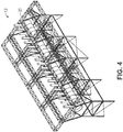
- FIG. 4 is a perspective view of the air cooled condenser module 12 depicted in FIG. 1 in accordance with an embodiment of the present invention. As shown in FIG. 4 , the headers 26, top manifold 28 and bundles 30 as well as the fan 32 and bell housing have been removed for clarity to show the understructure 20. In the following FIGS. 5-16 an inventive sequence of construction for the air cooled condenser module 12 is illustrated in accordance to an embodiment.
- a braced bay 50 is disposed a construction site for the air cooled condenser module 12 depicted in FIG. 1 .
- the braced bay 50 is configured to support one of the air cooled condenser modules 12 on four feet 52.
- a foundation is disposed in the ground below each of the feet 52.
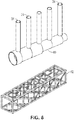
- FIG. 6 is a perspective view of a duct 60, the risers 24, and a middle truss 62 for the air cooled condenser module 12 depicted in FIG. 1 in accordance with an embodiment of the present invention.
- the risers 24 and duct 60 may be pre-assembled at a manufacturing facility and container shipped to the building site.
- the middle truss 62 may be pre-assembled at a manufacturing facility and container shipped to the building site.
- This and other pre-assembly described herein facilitates a reduction in labor costs and improvement in quality of construction. For example, at the production facility, welders may be protected from rain and other elements that may otherwise reduce weld quality.
- the risers 24 may be affixed to the duct 60 after placement on the understructure 20.
- FIG. 7 is a perspective view of an assembled duct 60, risers 24, and middle truss 62 for the air cooled condenser module 12 depicted in FIG. 1 in accordance with an embodiment of the present invention.
- the assembly may be performed on the ground at the building site or at the manufacturing facility.
- the assembled duct 60, risers 24, and middle truss 62 is shown disposed on the braced bay 50 for the air cooled condenser module 12 depicted in FIG. 1 .
- the assembled duct 60, risers 24, and middle truss 62 may be lifted by a crane and disposed on the braced bay 50.
- a plurality of transversal structures 90 are disposed on the assembled duct 60, risers 24, and middle truss 62 disposed on the braced bay 50 for the air cooled condenser module 12 depicted in FIG. 1 .
- the transversal structures 90 may be welded or bolted to the braced bay 50 after being lifted by the crane.
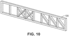
- FIG. 10 is a perspective view of a transversal truss 100 for the air cooled condenser module 12 depicted in FIG. 1 in accordance with an embodiment of the present invention.
- the transversal truss 100 may be pre-assembled at a manufacturing facility and container shipped to the building site.
- the transversal truss 100 is shown attached to the transversal structures 90 on the assembled duct 60, risers 24, and middle truss 62 disposed on the braced bay 50 for the air cooled condenser module 12 depicted in FIG. 1 .
- the transversal truss 100 may be welded or bolted to the transversal structures 90 after being lifted by the crane.
- FIG. 12 is a perspective view of a longitudinal truss 120 for the air cooled condenser module 12 depicted in FIG. 1 in accordance with an embodiment of the present invention.
- the longitudinal truss 120 may be pre-assembled at a manufacturing facility and container shipped to the building site.
- the longitudinal truss 120 is shown attached to the transversal truss 100.
- the longitudinal truss 120 may be welded or bolted to the transversal truss 100 after being lifted by the crane.
- FIG. 14 is a perspective view of a bridge 140 for the air cooled condenser module 12 depicted in FIG. 1 in accordance with an embodiment of the present invention.
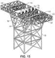
- the bridges 140 are connected to the transversal trusses 100 on the braced bay 50.
- the bridges 140 may be welded or bolted to the transversal truss 100 after being lifted by the crane.
- FIG. 16 is a perspective view of a partial placement of the headers 26 disposed on the risers 24.
- the headers 26 are shown connected to the top manifolds 28 which supply steam to the bundles 30.
- a delta 160 is an assembled set of top manifolds 28 and bundles 30.
- the air cooled condenser module 12 generally includes a plenum 170, having an air current generator or fan disposed within a fan shroud or inlet bell 34 and the understructure 20 is shown in a simplified form for the sake of clarity.
- the air cooled condenser module 12 further includes multiple A-type geometry deltas, each designated 160.
- Each delta 160 comprises two tube bundle assemblies 30 with a series of finned tubes to conduct heat transfer. The deltas 160 will be discussed in further detail below.
- FIGS. 18 and 19 schematic side views of the air cooled condenser module 12 are depicted.
- the air cooled condenser employs risers 24 which are welded to the main steam duct 22.
- the risers 24 are connected to a steam manifold 28 which operates to keep the steam flow velocity more constant.
- This above described configuration is part the A-type condenser bundles 30 that are shipped as a unit from the factory, which will be discussed in further detail below.
- the condenser bundles 30 are preferably welded to the risers 24 via a transition piece 26 to accommodate the geometry of the steam manifold.
- each delta 160 is comprised of two individual heat exchange bundle assemblies 30, each having a series of finned tubes.
- the individual tubes are approximately two (2) meters in length whereas the bundle length is approximately twelve (12) meters.
- each bundle assembly 30 is positioned at an angle to one another to form the A-type configuration of the delta 160. While the bundle assemblies 30 may be positioned at any desired angle, they preferably are positioned at an angle approximately twenty degrees (20°) to approximately thirty degrees (30°) from vertical and approximately sixty degrees (60°) to approximately seventy degrees (70°) from horizontal. More specifically, the bundle assemblies 30 are positioned at twenty-six degrees (26°) from vertical and sixty-four degrees (64°) from horizontal.
- each of the bundle assemblies 30 are assembled prior to shipping wherein each comprises a riser to header transition piece 202, steam manifold 204, finned tubes 206, and steam condensate headers 200.
- the air cooled condenser design 10 has approximately five (5) times more tubes as compared to typical designs.
- the embodiments of the current invention not only utilize five (5) times the tubes, but employ condenser tubes that are much shorter in length.
- the steam velocity traveling through the tube bundles 30 is reduced as result of the increased number of tubes in combination with the reduced tube length, and therefore steam pressure drop within the deltas 160 is reduced, making the air cool condenser 10 more efficient.
- turbine back pressure of an air cooled condenser or the like is limited by the maximum steam velocity in the tubes (to limit erosion) wherein the steam velocity is increasing with a decrease of back pressure (due to density of steam).
- the steam is still maintained at the maximum allowable steam velocity but at a lower back pressure.
- the other limitation the current delta design addresses is that the pressure at the exit of the secondary bundles cannot be less than the vacuum group capability. This pressure typically results from turbine back pressure minus the pressure drop in ducting minus the pressure drop in the tubes. Accordingly, due to the reduced pressure drop in the tubes, the allowable turbine back pressure is lower with the delta 160 design.
- the above-described bundle design also reduces the pressure drop within the individual delta 160.
- the heat exchange that takes place via the deltas 160 is dependent upon the heat exchange coefficient, i.e., the mean temperature difference between air and steam and the exchange surface. Due to the reduced pressure drop as previously described, the mean pressure (average between inlet pressure and exit pressure) in the exchanger is higher with the design of the current condenser configuration 12. In other words, because steam is saturated, the mean steam temperature is also higher for the same heat exchange surface resulting in increased heat exchange.
- a transport container generally designated 210 is illustrated.
- the transport container 210 is used to transport the bundles 30, from the factory to the job site.
- the condenser bundles 30, are manufactured and assembled at the factory with the respective steam manifold 204 and steam condensate headers 200. While five (5) bundles are illustrated positioned in the transport container, more or less individual bundles may be shipped per container depending as needed or required.
- alternative embodiment bundles may not include a manifold prior to shipping. More specifically, in such embodiments, the tube bundles may be ship without steam manifolds 28 attached thereto. In said embodiments, the tube bundles 30 may be assembled in field to form the A-type configuration, as discussed above. However, instead of employing two steam manifolds, this alternative embodiment may employ a single steam manifold wherein the single steam manifold extends along the "apex" of the A configuration.
- each individual bundle assembly 30 includes a plurality of finned tubes 206 along with a steam manifold 204 and steam condensate header 200.
- the bundle assemblies 30 are pre-manufactured at the factory prior to placing the individual bundle assemblies 30 in the shipping container 210 as identified by numeral 42. The shipping containers 210 are then shipped to the erection field site.
- the delta is assembled in the field as identified by numerals 216 and 218.
- the bundles may be positioned at any desired angle, they preferably are positioned at an angle (y) approximately twenty degrees (20°) to approximately thirty degrees (30°) from vertical and an angle (x) approximately sixty degrees (60°) to approximately seventy degrees (70°) from horizontal. More specifically, the bundles are positioned at twenty-six degrees (26°) from vertical and sixty-four degrees (64°) from horizontal.
- a single A-type delta is illustrated 160 formed by two bundle assemblies 30 to form the "A" configuration. The bundle assemblies 30 self support one another in this configuration.
- the air cooled condenser module 12 as referenced by the numeral 220, it is depicted employing five deltas 160.
- the air cooled condenser is an improvement over current air cooled condenser types and it has a high "prefabrication" level which equates to reduced installation cost and reduced installation time.
- the above-described design reduces the pressure drop, thereby providing a more efficient heat exchange apparatus.
- Tables 1 and 2 below show the number of parts utilized for a 32 module Multi-Delta and a 30 module A-Frame ACC designed for the same duty. There is a very dramatic decrease in pieces which translates in to substantially less construction labor and construction time.
- Table 1 Multidelta Type 1 Number 2 Type 4 Number 2 Understrucure Columns 12 Understrucure Columns 6 Bracing 36 Bracing 6 Horizontal beams 8 Horizontal beams 6 Other 26 Other 13 Plenum Middle truss 1 Plenum Middle truss 1 Transversal truss 4 Transversal truss 2 Longitudinal truss 2 Longitudinal truss 0.5 Octogonal structure 16 Octogonal structure 16 Fan deck plate 24 Fan deck plate 24 Bridge 4 Bridge 4 Horizontal wind bracing 4 Horizontal wind bracing 2 Wind wall longitudinal Horizontal girder 2 Wind wall longitudinal Horizontal girder 0 Wind wall transversal Horizontal girder 0 Wind wall transversal Horizontal girder 0 Sum of elements 278 Sum
- the multidelta ACC of an embodiment disclosed herein includes less than half the parts of a comparable conventional A-Frame ACC (2125 parts verses 5148 parts). This reduction in part numbers has a corresponding reduction in labor costs, construction time, and the like.
Landscapes
- Engineering & Computer Science (AREA)
- Mechanical Engineering (AREA)
- General Engineering & Computer Science (AREA)
- Architecture (AREA)
- Physics & Mathematics (AREA)
- Thermal Sciences (AREA)
- Civil Engineering (AREA)
- Structural Engineering (AREA)
- Chemical & Material Sciences (AREA)
- Combustion & Propulsion (AREA)
- Heat-Exchange Devices With Radiators And Conduit Assemblies (AREA)
- Details Of Heat-Exchange And Heat-Transfer (AREA)
Description
- This application claims priority to
U.S. Provisional Application Serial No. 61/828,076, filed on May 28, 2013 - The present invention relates to a mechanical draft cooling tower that utilizes air cooled condenser modules. The aforementioned cooling tower operates by mechanical draft and achieves the exchange of heat between two fluids such as atmospheric air, ordinarily, and another fluid which is usually steam or some sort of industrial process fluid. The aforementioned cooling tower operates by mechanical draft which utilizes an air current generator such as a fan or the like.
- Cooling towers are heat exchangers of a type widely used to emanate low grade heat to the atmosphere and are typically utilized in electricity generation, air conditioning installations and the like. In a mechanical draft cooling tower for the aforementioned applications, airflow is induced or forced via an air flow generator such as a driven impeller, driven fan or the like. Cooling towers may be wet or dry. Dry cooling towers can be either "direct dry," in which steam is directly condensed by air passing over a heat exchange medium containing the steam or an "indirect dry" type cooling towers, in which the steam first passes through a surface condenser cooled by a fluid and this warmed fluid is sent to a cooling tower heat exchanger where the fluid remains isolated from the air, similar to an automobile radiator. Dry cooling has the advantage of no evaporative water losses. Both types of dry cooling towers dissipate heat by conduction and convection and both types are presently in use. Wet cooling towers provide direct air contact to a fluid being cooled. Wet cooling towers benefit from the latent heat of vaporization which provides for very efficient heat transfer but at the expense of evaporating a small percentage of the circulating fluid.
- To accomplish the required direct dry cooling the condenser typically requires a large surface area to dissipate the thermal energy in the gas or steam and oftentimes may present several challenges to the design engineer. It sometimes can be difficult to efficiently and effectively direct the steam to all the inner surface areas of the condenser because of nonuniformity in the delivery of the steam due to system ducting pressure losses and velocity distribution. Therefore, uniform steam distribution is desirable in air cooled condensers and is critical for optimum performance. Another challenge or drawback is, while it is desirable to provide a large surface area, steam side pressure drop may be generated thus increasing turbine back pressure and consequently reducing efficiency of the power plant. Therefore it is desirous to have a condenser with a strategic layout of ducting and condenser surfaces that allows for an even distribution of steam throughout the condenser that reduces back pressure, while permitting a maximum of cooling airflow throughout and across the condenser surfaces.
- Another drawback to the current air cooled condenser towers is that they are typically very labor intensive in their assembly at the job site. The assembly of such towers oftentimes requires a dedicated labor force, investing a large amount of hours. Accordingly, such assembly is labor intensive requiring a large amount of time and therefore can be costly. Accordingly, it is desirable and more efficient to assemble as much of the tower structure at the manufacturing plant or facility, prior to shipping it to the installation site.
- It is well known in the art that improving cooling tower performance (i.e. the ability to extract an increased quantity of waste heat in a given surface) can lead to improved overall efficiency of a steam plant's conversion of heat to electric power and/or to increases in power output in particular conditions. Moreover, cost-effective methods of manufacture and assembly also improve the overall efficiency of cooling towers in terms of cost-effectiveness of manufacture and operation. Accordingly, it is desirable for cooling tower that are efficient in both in the heat exchange properties and assembly. The present invention addresses this desire.
- Therefore it would desirous to have an economical, mechanical draft, modular cooling tower that is efficient not only in its heat exchange properties but also in its time required for assembly and cost for doing the same.
WO 2008/110154 discloses a method for assembling an understructure for a modular air cooled condenser according to the preamble of claim 1 and a modular understructure for an air cooled condenser according to the preamble of claim 11. - Embodiments of the present invention advantageously provides for a fluid, usually steam and method for a modular mechanical draft cooling tower for condensing said steam.
- An embodiment of the invention includes a method for assembling a modular air cooled condenser extending along a vertical axis away from horizontal, comprising the steps of: assembling a first condenser bundle assembly having a first set of tubes having first and second ends, a steam manifold connected to the first ends of the tubes , and a condensate header connected to the second ends of the tubes ; assembling a second condenser bundle having a second set of tubes having first and second ends, a steam manifold connected to the first ends of the tubes, and a condensate header connected to the second ends of the tubes; placing the first and second condenser bundle assemblies in to a container; transporting the container to a location upon which the modular air cooled condenser will be assembled; assembling a heat exchange delta by placing the first condenser bundle and the second condenser bundle; and positioning the heat exchange delta on a modular tower frame.
- Another embodiment of the present invention includes a modular air cooled condenser extending along a vertical axis away from horizontal, comprising: means for assembling a first condenser bundle assembly having a first set of tubes having first and second ends, a steam manifold connected to the first ends of the tubes, and a condensate header connected to the second ends of the tubes; means for assembling a second condenser bundle assembly having a second set of tubes having first and second ends, a steam manifold connected to the first end of the tubes, and a condensate header connected to the second ends of the tubes; means for placing the first and second condenser bundle assemblies in to a container; means for transporting the container to a location upon which the modular air cooled condenser will be assembled; means for assembling a heat exchange delta by placing using the first condenser bundle and the second condenser bundle; and means for positioning the heat exchange delta on a modular tower frame.
- Another embodiment of the present invention, A mechanical draft modular air cooled condenser that cools an industrial fluid is disclosed, comprising: a plenum with which at least one delta resides wherein said at least one delta comprises first condenser bundle having a first set of tubes having first and second ends, a steam manifold connected to the first ends of the tubes, and a condensate header connected to the second ends of the tubes; and a second condenser bundle having a second set of tubes having first and second ends, a steam manifold connected to the first ends of the tubes, and a condensate header connected to the second ends of the tubes; a support frame that supports said plenum; and a shroud that houses an air current generator.
- In yet another embodiment of the present invention, a method for assembling a modular air cooled condenser extending along a vertical axis is disclosed, comprising: assembling a first condenser bundle having a first set of tubes having first and second ends and a condensate header connected to the second end of the tubes; assembling a second condenser bundle having a second set of tubes having first and second ends, and a condensate header connected to the second end of the tubes; placing the first and second condenser bundles in to a container; transporting the container to a location upon which the modular air cooled condenser will be assembled; assembling a heat exchange delta by placing using the first condenser bundle and the second condenser bundle; and positioning the heat exchange delta on a modular tower frame.
- There has thus been outlined, rather broadly, certain embodiments of the invention in order that the detailed description thereof herein may be better understood, and in order that the present contribution to the art may be better appreciated. There are, of course, additional embodiments of the invention that will be described below and which will form the subject matter of the claims appended hereto.
- In this respect, before explaining at least one embodiment of the invention in detail, it is to be understood that the invention is not limited in its application to the details of construction and to the arrangements of the components set forth in the following description or illustrated in the drawings. The invention is capable of embodiments in addition to those described and of being practiced and carried out in various ways. Also, it is to be understood that the phraseology and terminology employed herein, as well as the abstract, are for the purpose of description and should not be regarded as limiting.
- As such, those skilled in the art will appreciate that the conception upon which this disclosure is based may readily be utilized as a basis for the designing of other structures, methods and systems for carrying out the several purposes of the present invention.
- The above-mentioned and other features and advantages of this disclosure, and the manner of attaining them, will become more apparent and the disclosure itself will be better understood by reference to the following description of various embodiments of the disclosure taken in conjunction with the accompanying figures.
-
FIG. 1 is a top view of a power plant with heat exchanger having an air cooled condenser module in accordance with an embodiment of the present invention. -
FIG. 2 is an elevation view of the air cooled condenser module depicted inFIG. 1 in accordance with an embodiment of the present invention. -
FIG. 3 is a sectional view of the air cooled condenser module depicted inFIG. 1 in accordance with an embodiment of the present invention. -
FIG. 4 is a perspective view of the air cooled condenser module depicted inFIG. 1 in accordance with an embodiment of the present invention. -
FIG. 5 is a perspective view of a braced bay for the air cooled condenser module depicted inFIG. 1 in accordance with an embodiment of the present invention. -
FIG. 6 is a perspective view of a duct, risers, and middle truss for the air cooled condenser module depicted inFIG. 1 in accordance with an embodiment of the present invention. -
FIG. 7 is a perspective view of an assembled duct, risers, and middle truss for the air cooled condenser module depicted inFIG. 1 in accordance with an embodiment of the present invention. -
FIG. 8 is a perspective view of the assembled duct, risers, and middle truss disposed on the braced bay for the air cooled condenser module depicted inFIG. 1 in accordance with an embodiment of the present invention. -
FIG. 9 is a perspective view of transversal structures on the assembled duct, risers, and middle truss disposed on the braced bay for the air cooled condenser module depicted inFIG. 1 in accordance with an embodiment of the present invention. -
FIG. 10 is a perspective view of a transversal truss for the air cooled condenser module depicted inFIG. 1 in accordance with an embodiment of the present invention. -
FIG. 11 is a perspective view of the transversal truss and transversal structures on the assembled duct, risers, and middle truss disposed on the braced bay for the air cooled condenser module depicted inFIG. 1 in accordance with an embodiment of the present invention. -
FIG. 12 is a perspective view of a longitudinal truss for the air cooled condenser module depicted inFIG. 1 in accordance with an embodiment of the present invention. -
FIG. 13 is a perspective view of the longitudinal truss, transversal truss, and transversal structures on the assembled duct, risers, and middle truss disposed on the braced bay for the air cooled condenser module depicted inFIG. 1 in accordance with an embodiment of the present invention. -
FIG. 14 is a perspective view of a bridge for the air cooled condenser module depicted inFIG. 1 in accordance with an embodiment of the present invention. -
FIG. 15 is a perspective view of the bridges, longitudinal trusses, transversal trusses, and transversal structures on the assembled duct, risers, and middle truss disposed on the braced bay for the air cooled condenser module depicted inFIG. 1 in accordance with an embodiment of the present invention. -
FIG. 16 is a perspective view of a partial placement of headers and deltas for the air cooled condenser module depicted inFIG. 1 in accordance with an embodiment of the present invention. -
FIG. 17 is a perspective view of an air cooled condenser module in accordance with an embodiment of the present invention. -
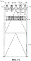
FIG. 18 is a schematic side view of the air cooled condenser module depicted inFIG. 1 in accordance with an embodiment of the present invention. -
FIG. 19 is another schematic side view of the air cooled condenser module depicted inFIG. 1 in accordance with an embodiment of the present invention. -
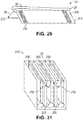
FIG. 20 is a perspective view of an A-type condenser configuration in accordance with an embodiment of the present invention. -
FIG. 21 illustrates the condenser bundles in a packaged arrangement for shipping in accordance with an embodiment of the present invention. -
FIG. 22 schematically illustrates the steps of assembly of an air cooled condenser in accordance with an embodiment of the present invention. - In the following detailed description, reference is made to the accompanying drawings, which form a part hereof and show by way of illustration specific embodiments in which the invention may be practiced. These embodiments are described in sufficient detail to enable those skilled in the art to practice them, and it is to be understood that other embodiments may be utilized, and that structural, logical, processing, and electrical changes may be made. It should be appreciated that any list of materials or arrangements of elements is for example purposes only and is by no means intended to be exhaustive. The progression of processing steps described is an example; however, the sequence of steps is not limited to that set forth herein and may be changed as is known in the art, with the exception of steps necessarily occurring in a certain order.
- Embodiments described herein provide a heat exchange system, a support structure for an air cooled condenser ("ACC"), and a method of constructing a support structure for an ACC. As described herein, some or all of these embodiments provide substantial benefit over standard A-frame ACC. Examples of benefits over standard A-frame ACC include reduced cost of about 25%, improved constructability, higher annual output of power plant, improved cleanability due to use of motorized cleaning shuttlestandard, lower visual impact due to reduced height (26m vs. 32.6m) and reduced occupied ground area, and reduced foundations (40 columns vs 48 for A-frame ACC with equivalent output). This height reduction is due to the reduced height of the multi-deltas described herein compared to conventional A-Frame-type bundles that have longer tubes and increased overall height.
- Specific examples of reduced cost and improved constructability include: Steam manifolds and steam condensate headers already welded on finned tube bundles in the manufacturing factory; Less total weight of steel structure (- 25% vs A-Frame ACC); Less total weight of ducting (- 25% vs A-Frame ACC); Reduced number of bundles (25% for A-Frame ACC); Fewer elements of steel structure to be assembled on site by bolting (- 50% vs A-Frame ACC); Reduced site welding length on ducting (- 50% vs A-frame ACC); Fewer lifting operations; Shorter construction duration; Fewer man activities at height due to more preassembly which results in improved overall safety level; Less scaffolding required; Higher proportion of piping and piping supports preassembled in the manufacturing factory on the finned tube bundles; Important proportion of assembly on site is at ground level (bolting of delta, liaison duct, ...); No cleaning ladder required; and More containerized deliveries.
- Specific examples of higher annual output of power plant include: Lower back-pressure during low ambient temperature periods (e.g., below 9 °C) which results in higher power plant output during low temperature periods; and lower minimum back-pressure (62 mbar vs 70 mbar for A-Frame ACC) which results in higher power plant electricity production on a yearly basis (+ 0.4 % vs A-Frame ACC). More particularly, the back-pressure may be reduced because the heat exchange tubes in the bundles (described herein) may be made shorter and more numerous in comparison to an A-Frame ACC. In this manner, the total surface area may be equivalent while the velocity in the tubes is reduced. It is yet another advantage that the reduced velocity results in a corresponding reduction in erosion of the tubing.
-
FIG. 1 is a top view of aheat exchange system 10 having an air cooledcondenser module 12 in accordance with an embodiment of the present invention that is suitable for use with a heat generating facility such as apower plant 14. As shown inFIG. 1 , theheat exchange system 10 includes an understructure 20 to support the other elements of theheat exchange system 10 such as asupply line 22,risers 24,headers 26,top manifold 28, coils or bundles 30,fan 32 andbell housing 34. In addition, areturn line 36 is configured to return condensate to thepower plant 14. - In use, the
power plant 14 generates heat to create steam to drive turbines to generate power in a manner generally known to those skilled in the art. After steam has passed through the turbines, the steam still retains substantial waste heat which is removed by theheat exchange system 10 and the condensate is returned via thereturn line 36. -
FIG. 2 is an elevation view of the air cooledcondenser module 12 depicted inFIG. 1 in accordance with an embodiment of the present invention. As shown inFIG. 2 , theunderstructure 20 occupies a relatively small area which results in great open space below the air cooledcondenser module 12. -
FIG. 3 is a sectional view of the air cooledcondenser module 12 depicted inFIG. 1 in accordance with an embodiment of the present invention. As shown inFIG. 3 , thesupply line 22 is depicted reducing in size as it proceeds along the air cooledcondenser module 12. In general, as therisers 24 channel steam from thesupply line 22 to thetop manifold 28 and bundles 30, the size of thesupply line 22 is reduced accordingly. -
FIG. 4 is a perspective view of the air cooledcondenser module 12 depicted inFIG. 1 in accordance with an embodiment of the present invention. As shown inFIG. 4 , theheaders 26,top manifold 28 and bundles 30 as well as thefan 32 and bell housing have been removed for clarity to show the understructure 20. In the followingFIGS. 5-16 an inventive sequence of construction for the air cooledcondenser module 12 is illustrated in accordance to an embodiment. - At
FIG. 5 , a bracedbay 50 is disposed a construction site for the air cooledcondenser module 12 depicted inFIG. 1 . The bracedbay 50 is configured to support one of the air cooledcondenser modules 12 on fourfeet 52. In typical construction, a foundation is disposed in the ground below each of thefeet 52. -
FIG. 6 is a perspective view of aduct 60, therisers 24, and amiddle truss 62 for the air cooledcondenser module 12 depicted inFIG. 1 in accordance with an embodiment of the present invention. As shown inFIG. 6 , therisers 24 andduct 60 may be pre-assembled at a manufacturing facility and container shipped to the building site. Similarly, themiddle truss 62 may be pre-assembled at a manufacturing facility and container shipped to the building site. This and other pre-assembly described herein facilitates a reduction in labor costs and improvement in quality of construction. For example, at the production facility, welders may be protected from rain and other elements that may otherwise reduce weld quality. However, in other embodiments, therisers 24 may be affixed to theduct 60 after placement on theunderstructure 20. -
FIG. 7 is a perspective view of an assembledduct 60,risers 24, andmiddle truss 62 for the air cooledcondenser module 12 depicted inFIG. 1 in accordance with an embodiment of the present invention. In an embodiment, the assembly may be performed on the ground at the building site or at the manufacturing facility. AtFIG. 8 , the assembledduct 60,risers 24, andmiddle truss 62 is shown disposed on the bracedbay 50 for the air cooledcondenser module 12 depicted inFIG. 1 . For example, the assembledduct 60,risers 24, andmiddle truss 62 may be lifted by a crane and disposed on the bracedbay 50. - At
FIG. 9 , a plurality oftransversal structures 90 are disposed on the assembledduct 60,risers 24, andmiddle truss 62 disposed on the bracedbay 50 for the air cooledcondenser module 12 depicted inFIG. 1 . For example, thetransversal structures 90 may be welded or bolted to the bracedbay 50 after being lifted by the crane. -
FIG. 10 is a perspective view of atransversal truss 100 for the air cooledcondenser module 12 depicted inFIG. 1 in accordance with an embodiment of the present invention. Thetransversal truss 100 may be pre-assembled at a manufacturing facility and container shipped to the building site. AtFIG. 11 , thetransversal truss 100 is shown attached to thetransversal structures 90 on the assembledduct 60,risers 24, andmiddle truss 62 disposed on the bracedbay 50 for the air cooledcondenser module 12 depicted inFIG. 1 . For example, thetransversal truss 100 may be welded or bolted to thetransversal structures 90 after being lifted by the crane. -
FIG. 12 is a perspective view of alongitudinal truss 120 for the air cooledcondenser module 12 depicted inFIG. 1 in accordance with an embodiment of the present invention. Thelongitudinal truss 120 may be pre-assembled at a manufacturing facility and container shipped to the building site. AtFIG. 13 , thelongitudinal truss 120 is shown attached to thetransversal truss 100. For example, thelongitudinal truss 120 may be welded or bolted to thetransversal truss 100 after being lifted by the crane. -
FIG. 14 is a perspective view of abridge 140 for the air cooledcondenser module 12 depicted inFIG. 1 in accordance with an embodiment of the present invention. AtFIG. 15 , thebridges 140 are connected to thetransversal trusses 100 on the bracedbay 50. For example, thebridges 140 may be welded or bolted to thetransversal truss 100 after being lifted by the crane. -
FIG. 16 is a perspective view of a partial placement of theheaders 26 disposed on therisers 24. Theheaders 26 are shown connected to thetop manifolds 28 which supply steam to thebundles 30. Adelta 160 is an assembled set oftop manifolds 28 and bundles 30. - Turning now to
FIG. 17 , the modular air cooledcondenser module 12 is illustrated on a simplified understructure. The air cooledcondenser module 12 generally includes aplenum 170, having an air current generator or fan disposed within a fan shroud orinlet bell 34 and the understructure 20 is shown in a simplified form for the sake of clarity. The air cooledcondenser module 12 further includes multiple A-type geometry deltas, each designated 160. Eachdelta 160 comprises twotube bundle assemblies 30 with a series of finned tubes to conduct heat transfer. Thedeltas 160 will be discussed in further detail below. - Turning now to
FIGS. 18 and19 , schematic side views of the air cooledcondenser module 12 are depicted. As specifically illustrated inFIG. 18 , the air cooled condenser employsrisers 24 which are welded to themain steam duct 22. Therisers 24 are connected to asteam manifold 28 which operates to keep the steam flow velocity more constant. This above described configuration is part the A-type condenser bundles 30 that are shipped as a unit from the factory, which will be discussed in further detail below. The condenser bundles 30 are preferably welded to therisers 24 via atransition piece 26 to accommodate the geometry of the steam manifold. - Turning now to
FIG. 20 , adelta 160 is illustrated. As depicted, eachdelta 160 is comprised of two individual heatexchange bundle assemblies 30, each having a series of finned tubes. The individual tubes are approximately two (2) meters in length whereas the bundle length is approximately twelve (12) meters. As illustrated, eachbundle assembly 30 is positioned at an angle to one another to form the A-type configuration of thedelta 160. While thebundle assemblies 30 may be positioned at any desired angle, they preferably are positioned at an angle approximately twenty degrees (20°) to approximately thirty degrees (30°) from vertical and approximately sixty degrees (60°) to approximately seventy degrees (70°) from horizontal. More specifically, thebundle assemblies 30 are positioned at twenty-six degrees (26°) from vertical and sixty-four degrees (64°) from horizontal. - Each of the
bundle assemblies 30 are assembled prior to shipping wherein each comprises a riser toheader transition piece 202,steam manifold 204,finned tubes 206, andsteam condensate headers 200. As can be seen inFIG. 17 , due to the modular design and orientation of thebundle assemblies 30, the air cooledcondenser design 10 has approximately five (5) times more tubes as compared to typical designs. Moreover, the embodiments of the current invention not only utilize five (5) times the tubes, but employ condenser tubes that are much shorter in length. As result of the aforementioned design and orientation, the steam velocity traveling through the tube bundles 30 is reduced as result of the increased number of tubes in combination with the reduced tube length, and therefore steam pressure drop within thedeltas 160 is reduced, making the aircool condenser 10 more efficient. - Typically, turbine back pressure of an air cooled condenser or the like is limited by the maximum steam velocity in the tubes (to limit erosion) wherein the steam velocity is increasing with a decrease of back pressure (due to density of steam). Thus, due to the addition of tubes in accordance with the present invention, the steam is still maintained at the maximum allowable steam velocity but at a lower back pressure. The other limitation the current delta design addresses is that the pressure at the exit of the secondary bundles cannot be less than the vacuum group capability. This pressure typically results from turbine back pressure minus the pressure drop in ducting minus the pressure drop in the tubes. Accordingly, due to the reduced pressure drop in the tubes, the allowable turbine back pressure is lower with the
delta 160 design. - Furthermore, the above-described bundle design also reduces the pressure drop within the
individual delta 160. For example, the heat exchange that takes place via thedeltas 160, is dependent upon the heat exchange coefficient, i.e., the mean temperature difference between air and steam and the exchange surface. Due to the reduced pressure drop as previously described, the mean pressure (average between inlet pressure and exit pressure) in the exchanger is higher with the design of thecurrent condenser configuration 12. In other words, because steam is saturated, the mean steam temperature is also higher for the same heat exchange surface resulting in increased heat exchange. - Turning now to
FIG. 21 , a transport container, generally designated 210 is illustrated. As the name suggests, thetransport container 210 is used to transport thebundles 30, from the factory to the job site. As illustrated, the condenser bundles 30, are manufactured and assembled at the factory with therespective steam manifold 204 andsteam condensate headers 200. While five (5) bundles are illustrated positioned in the transport container, more or less individual bundles may be shipped per container depending as needed or required. - Alternatively, the above described embodiments of the present employ tube bundles manufactured and assembled, prior to shipping, having
steam manifold 204 andsteam condensate headers 200, alternative embodiment bundles may not include a manifold prior to shipping. More specifically, in such embodiments, the tube bundles may be ship withoutsteam manifolds 28 attached thereto. In said embodiments, the tube bundles 30 may be assembled in field to form the A-type configuration, as discussed above. However, instead of employing two steam manifolds, this alternative embodiment may employ a single steam manifold wherein the single steam manifold extends along the "apex" of the A configuration. - Referring now to
FIG. 22 , a flow chart is illustrated, schematically depicting the steps of assembly of the air cooledcondenser tower 12. As previously described, the individual tube bundles 30 are assembled prior to shipment to the job site, as referenced bynumeral 212. Eachindividual bundle assembly 30 includes a plurality offinned tubes 206 along with asteam manifold 204 andsteam condensate header 200. As previously discussed in connection with the previous figures of the specification, thebundle assemblies 30 are pre-manufactured at the factory prior to placing theindividual bundle assemblies 30 in theshipping container 210 as identified by numeral 42. Theshipping containers 210 are then shipped to the erection field site. - Next, the delta, generally indicated as 160, is assembled in the field as identified by
numerals numeral 220, a single A-type delta is illustrated 160 formed by twobundle assemblies 30 to form the "A" configuration. Thebundle assemblies 30 self support one another in this configuration. - Turning now to the air cooled
condenser module 12 as referenced by the numeral 220, it is depicted employing fivedeltas 160. As discussed above, the air cooled condenser is an improvement over current air cooled condenser types and it has a high "prefabrication" level which equates to reduced installation cost and reduced installation time. Moreover, the above-described design reduces the pressure drop, thereby providing a more efficient heat exchange apparatus. - Tables 1 and 2 below show the number of parts utilized for a 32 module Multi-Delta and a 30 module A-Frame ACC designed for the same duty. There is a very dramatic decrease in pieces which translates in to substantially less construction labor and construction time.
Table 1: Multidelta Type 1 Number 2 Type 4 Number 2 Understrucure Columns 12 Understrucure Columns 6 Bracing 36 Bracing 6 Horizontal beams 8 Horizontal beams 6 Other 26 Other 13 Plenum Middle truss 1 Plenum Middle truss 1 Transversal truss 4 Transversal truss 2 Longitudinal truss 2 Longitudinal truss 0.5 Octogonal structure 16 Octogonal structure 16 Fan deck plate 24 Fan deck plate 24 Bridge 4 Bridge 4 Horizontal wind bracing 4 Horizontal wind bracing 2 Wind wall longitudinal Horizontal girder 2 Wind wall longitudinal Horizontal girder 0 Wind wall transversal Horizontal girder 0 Wind wall transversal Horizontal girder 0 Sum of elements 278 Sum of elements 161 Type 2 Number 2 Type 5 Number 4 Understrucure Columns 12 Understrucure Columns 6 Bracing 36 Bracing 6 Horizontal beams 8 Horizontal beams 6 Other 26 Other 13 Plenum Middle truss 1 Plenum Middle truss 1 Transversal truss 4 Transversal truss 2 Longitudinal truss 1 Longitudinal truss 2 Octogonal structure 16 Octogonal structure 16 Fan deck plate 24 Fan deck plate 24 Bridge 4 Bridge 4 Horizontal wind bracing 4 Horizontal wind bracing 2 Wind wall longitudinal Horizontal girder 0 Wind wall longitudinal Horizontal girder 2 Wind wall transversal Horizontal girder 0 Wind wall transversal sheeting support 1.5 Sum of elements 272 Sum of elements 342 Type 3 Number 2 Type 6 Number 4 Understrucure Columns 6 Understrucure Columns 6 Bracing 6 Bracing 6 Horizontal beams 6 Horizontal beams 6 Other 13 Other 13 Plenum Middle truss 1 Plenum Middle truss 1 Transversal truss 2 Transversal truss 2 Longitudinal truss 2 Longitudinal truss 0.5 Octogonal structure 16 Octogonal structure 16 Fan deck plate 24 Fan deck plate 24 Bridge 4 Bridge 4 Horizontal wind bracing 2 Horizontal wind bracing 2 Wind wall longitudinal Horizontal girder 2 Wind wall longitudinal Horizontal girder 0 Wind wall transversal Horizontal girder 0 Wind wall transversal Horizontal girder 1.5 Sum of elements 168 Sum of elements 328 Bundle bottom girder 256 External transversal walkways (with grating) 320 Total assembly part for 32 modules multidelta 2125 Table 2: ACC Type 1 Number 1 Type 4 Number 2 Understrucure Columns 8 Understrucure Columns 4 Bracing 24 Bracing 10 Horizontal beams 4 Horizontal beams 3 Support longitudinal wind wall 0 Support longitudinal wind wall 4 Fan deck Main beams 4 Fan deck Main beams 3 Octogonal structure 16 Octogonal structure 16 Bridge Main truss 1 Bridge Main truss 1 Bridge foot 4 Bridge foot 4 Handrails 4 Handrails 4 Gratings 10 Gratings 10 A-frame Columns 6 A-frame Columns 6 Top A 3 Top A 3 Bracings 8 Bracings 8 Top girder 2 Top girder 2 Mini a-frame 4 Mini a-frame 4 Stick to middle of bridge 4 Stick to middle of bridge 4 Hoist beam and support 4 Hoist beam and support 4 Mid a-frame tranversal 3 Mid a-frame tranversal 3 Mid a-frame longitudinal 4 Mid a-frame longitudinal 4 Stick to end of bridge 4 Stick to end of bridge 4 Internal girder and door frame 16 Internal girder and door frame 16 Angle for middle valley sheeting 4 Angle for middle valley sheeting 4 Wind wall longitudinal Columns 0 Wind wall longitudinal Columns 7 Horizontal girder 0 Horizontal girder 30 Bracings 0 Bracings 6 Link to SDM 0 Link to SDM 7 Tranversal walkway 0 Transversal walkway 1 Diamond plate 0 Diamond plate 10 Wind wall transversal Columns 0 Wind wall transversal Columns 0 Girders 0 Girders 0 Cleaning system Bottom rail 4 Cleaning system Bottom rail 4 Top rail 4 Top rail 4 Grating 10 Grating 0 Sum of elements 155 Sum of elements 380 Type 2 Number 2 Type 5 Number 4 Understrucure Columns 4 Understrucure Columns 2 Bracing 10 Bracing 4 Horizontal beams 3 Horizontal beams 2 Support longitudinal wind wall 0 Support longitudinal wind wall 2 Fan deck Main beams 3 Fan deck Main beams 2 Octogonal structure 16 Octogonal structure 16 Bridge Main truss 1 Bridge Main truss 1 Bridge foot 4 Bridge foot 4 Handrails 4 Handrails 4 Gratings 10 Gratings 10 A-frame Columns 4 A-frame Columns 4 Top A 2 Top A 2 Bracings 0 Bracings 0 Top girder 2 Top girder 2 Mini a-frame 2 Mini a-frame 2 Stick to middle of bridge 4 Stick to middle of bridge 4 Hoist beam and support 4 Hoist beam and support 4 Mid a-frame tranversal 2 Mid a-frame tranversal 2 Mid a-frame longitudinal 4 Mid a-frame longitudinal 4 Stick to end of bridge 2 Stick to end of bridge 2 Internal girder and door frame 8 Internal girder and door frame 8 Angle for middle valley sheeting 4 Angle for middle valley sheeting 4 Wind wall longitudinal Columns 0 Wind wall longitudinal Columns 6 Horizontal girder 0 Horizontal girder 30 Bracings 0 Bracings 6 Link to SDM 0 Link to SDM 6 Longitudinal walkway 0 Longitudinal walkway 1 Diamond plate 0 Diamond plate 10 Wind wall Columns 0 Wind wall Columns 0 transversal transversal Girders 0 Girders 0 Cleaning system Bottom rail 4 Cleaning system Bottom rail 4 Top rail 4 Top rail 4 Grating 6 Grating 0 Sum of elements 214 Sum of elements 608 Type 3 Number 2 Type 6 Number 4 Understrucure Columns 4 Understrucure Columns 2 Bracing 10 Bracing 4 Horizontal beams 3 Horizontal beams 2 Support longitudinal wind wall 0 Support longitudinal wind wall 2 Fan deck Main beams 3 Fan deck Main beams 2 Octogonal structure 16 Octogonal structure 16 Bridge Main truss 1 Bridge Main truss 1 Bridge foot 4 Bridge foot 4 Handrails 4 Handrails 4 Gratings 10 Gratings 10 A-frame Columns 4 A-frame Columns 4 Top A 2 Top A 2 Bracings 0 Bracings 0 Top girder 2 Top girder 2 Mini a-frame 2 Mini a-frame 2 Stick to middle of bridge 4 Stick to middle of bridge 4 Hoist beam and support 4 Hoist beam and support 4 Mid a-frame tranversal 2 Mid a-frame tranversal 2 Mid a-frame longitudinal 4 Mid a-frame longitudinal 4 Stick to end of bridge 2 Stick to end of bridge 2 Internal girder and door frame 3 Internal girder and door frame 3 Angle for middle valley sheeting 4 Angle for middle valley sheeting 4 Wind wall longitudinal Columns 0 Wind wall longitudinal Columns 6 Horizontal girder 0 Horizontal girder 30 Bracings 0 Bracings 14 Link to SDM 0 Link to SDM 5 Longitudinal walkway 0 Longitudinal walkway 1 Diamond plate 0 Diamond plate 10 Wind wall transversal Columns 4 Wind wall transversal Columns 3 Girders 20 Girders 17.5 Cleaning system Bottom rail 4 Cleaning system Bottom rail 4 Top rail 4 Top rail 4 Grating 6 Grating 0 Sum of elements 252 Sum of elements 698 Top Platform 21 Cleaning ladder 6 External transversal walkways (with grating) 240 Total assembly part for 30 modules ACC (2 units of 15 modules) 5148 - As shown in Tables 1 and 2, the multidelta ACC of an embodiment disclosed herein includes less than half the parts of a comparable conventional A-Frame ACC (2125 parts verses 5148 parts). This reduction in part numbers has a corresponding reduction in labor costs, construction time, and the like.
- The many features and advantages of the invention are apparent from the detailed specification, and, thus, it is intended by the appended claims to cover all such features and advantages of the invention which fall within the true spirit and scope of the invention. Further, since numerous modifications and variations will readily occur to those skilled in the art, it is not desired to limit the invention to the exact construction and operation illustrated and described, for example a forced draft air cooled condenser has been illustrated but an induced draft design can be adapted to gain the same benefits and, accordingly, all suitable modifications and equivalents may be resorted to that fall within the scope of the invention as described by the appended claims.
Claims (15)
- A method for assembling an understructure (20) for a modular air cooled condenser (12) extending along a vertical axis away from horizontal, comprising the method steps of:preparing a foundation for a braced bay (50); placing the braced bay (50) on the foundation;assembling a pre-constructed middle truss (62) with a pre-constructed duct (60) and risers;placing the assembled middle truss (62) and duct (60) on the braced bay (50);affixing a plurality of pre-constructed transversal structures (90) to the braced bay (50);affixing a plurality of pre-constructed transversal trusses (100) to the affixed transversal structures (90);affixing a plurality of pre-constructed longitudinal trusses (120) to ends of the (100) affixed transversal trusses (100) ; andaffixing a plurality of pre-constructed bridges (140) between ones of the affixed transversal trusses (100).
- The method according to claim 1, further comprising the method step of:affixing a header (26) to each respective riser (24).
- The method according to claim 2, further comprising the method step of:affixing a top manifold (28) to each respective header (26).
- The method according to claim 3, further comprising the method step of:affixing four of the top manifolds (28) to each respective header (26).
- The method according to claim 4, further comprising the method step of:affixing a bundle (30) to each respective top manifold (28).
- The method according to claim 1, further comprising the method step of:fluidly connecting a return line (36) to each bundle (30).
- The method according to claim 6, further comprising the method step of:fluidly connecting the return line (36) to a power plant (14).
- The method according to claim 1, further comprising the method step of:fluidly connecting a main steam line (22) to the duct (60).
- The method according to claim 8, further comprising the method step of:fluidly connecting the main steam line (22) to a power plant (14).
- The method according to claim 1, further comprising the method step of:affixing a bell housing (34) and a fan (32) to the understructure.
- A modular understructure (20) for an air cooled condenser (12) extending along a vertical axis away from horizontal, comprising:a braced bay (50) disposed on a foundation;an assembled pre-constructed middle truss (62) with a pre-constructed duct (60) and risers (24) disposed on the braced bay (50);a plurality of pre-constructed transversal structures (90) affixed to the braced bay (50);a plurality of pre-constructed transversal trusses (100) affixed to the affixed transversal structures (90);a plurality of pre-constructed longitudinal trusses (120) affixed to ends of the transversal trusses (100) ; anda plurality of pre-constructed bridges (140) affixed between ones of the transversal trusses (100).
- The modular understructure according to claim 11, further comprising:a header (26) affixed to each respective riser (24).
- The modular understructure according to claim 12, further comprising:a top manifold (28) affixed to each respective header (26).
- The modular understructure according to claim 13, further comprising:four of the top manifolds (28) affixed to each respective header (26).
- The modular understructure according to claim 14, further comprising:a bundle (30) affixed to each respective top manifold (28).
Applications Claiming Priority (2)
| Application Number | Priority Date | Filing Date | Title |
|---|---|---|---|
| US201361828076P | 2013-05-28 | 2013-05-28 | |
| PCT/US2014/039718 WO2014193916A1 (en) | 2013-05-28 | 2014-05-28 | Modular air cooled condenser apparatus and method |
Publications (3)
| Publication Number | Publication Date |
|---|---|
| EP3004777A1 EP3004777A1 (en) | 2016-04-13 |
| EP3004777A4 EP3004777A4 (en) | 2016-06-22 |
| EP3004777B1 true EP3004777B1 (en) | 2017-07-26 |
Family
ID=51989355
Family Applications (1)
| Application Number | Title | Priority Date | Filing Date |
|---|---|---|---|
| EP14804886.1A Active EP3004777B1 (en) | 2013-05-28 | 2014-05-28 | Modular air cooled condenser apparatus and method |
Country Status (6)
| Country | Link |
|---|---|
| US (1) | US20150345166A1 (en) |
| EP (1) | EP3004777B1 (en) |
| KR (1) | KR20160016886A (en) |
| CN (1) | CN105247314A (en) |
| ES (1) | ES2642077T3 (en) |
| WO (1) | WO2014193916A1 (en) |
Families Citing this family (14)
| Publication number | Priority date | Publication date | Assignee | Title |
|---|---|---|---|---|
| US9354002B2 (en) * | 2013-03-07 | 2016-05-31 | Spx Cooling Technologies, Inc. | Air cooled condenser apparatus and method |
| WO2016169076A1 (en) * | 2015-04-23 | 2016-10-27 | 赵元宾 | Column type cooling tube bundle with wedge-shaped gap |
| WO2017202730A1 (en) * | 2016-05-25 | 2017-11-30 | Spx Dry Cooling Belgium | Air-cooled condenser apparatus and method |
| RU2734089C2 (en) * | 2016-06-21 | 2020-10-12 | Эвапко, Инк. | Industrial steam condenser with completely secondary air cooling |
| US10982904B2 (en) | 2018-09-07 | 2021-04-20 | Evapco, Inc. | Advanced large scale field-erected air cooled industrial steam condenser |
| EP3287732B1 (en) * | 2016-08-24 | 2019-10-02 | SPG Dry Cooling Belgium | Induced draft air-cooled condenser |
| US11796255B2 (en) | 2017-02-24 | 2023-10-24 | Holtec International | Air-cooled condenser with deflection limiter beams |
| US11604030B2 (en) | 2017-09-27 | 2023-03-14 | Holtec International | Air-cooled condenser system |
| EP3688396B1 (en) | 2017-09-27 | 2023-07-26 | Holtec International | Air-cooled condenser system |
| US11852419B1 (en) * | 2018-03-29 | 2023-12-26 | Hudson Products Corporation | Air-cooled heat exchanger with tab and slot frame |
| CN112912670B (en) * | 2018-09-07 | 2023-07-18 | 艾威普科公司 | Advanced Large Scale Field Erected Air Cooled Industrial Steam Condenser |
| CA3154277A1 (en) * | 2019-09-13 | 2021-03-18 | Evapco, Inc. | Advanced large scale field-erected air cooled industrial steam condenser |
| CA3185801A1 (en) | 2022-04-13 | 2023-10-13 | John Jakic | Modular cooling tower structure, design, and method of assembly |
| CN114754621B (en) * | 2022-04-19 | 2025-12-30 | 富联精密电子(郑州)有限公司 | Energy-saving control methods, systems, electronic equipment and storage media for cooling towers |
Family Cites Families (14)
| Publication number | Priority date | Publication date | Assignee | Title |
|---|---|---|---|---|
| DE1601127B2 (en) * | 1967-02-08 | 1974-08-08 | Gkn Birwelco Ltd., Aston, Birmingham, Warwickshire (Grossbritannien) | Cooling system with a cooling tower working with natural draft |
| IT1135516B (en) * | 1981-02-18 | 1986-08-27 | Nuovo Pignone Spa | PERFECTED STEAM CONDENSER WITH AIR COOLING |
| US4913710A (en) * | 1989-05-11 | 1990-04-03 | Baltimore Aircoil Company, Inc. | Modular cooling tower |
| US5007501A (en) * | 1989-09-01 | 1991-04-16 | Baston Peter J | Apparatus for facilitating the internal inspection and repair of large pressure vessels |
| US5902522A (en) * | 1996-09-09 | 1999-05-11 | Baltimore Aircoil Company, Inc. | Rigid cooling tower and method of constructing a cooling tower |
| US5851446A (en) * | 1996-09-09 | 1998-12-22 | Baltimore Aircoil Company, Inc. | Rigid cooling tower |
| JP2002243386A (en) * | 2001-02-22 | 2002-08-28 | Toshiba Corp | Installation method of condenser |
| DE102007012539B4 (en) * | 2007-03-13 | 2011-03-03 | Gea Energietechnik Gmbh | condensation plant |
| US8302670B2 (en) * | 2007-12-28 | 2012-11-06 | Spx Cooling Technologies, Inc. | Air guide for air cooled condenser |
| US8235363B2 (en) * | 2008-09-30 | 2012-08-07 | Spx Cooling Technologies, Inc. | Air-cooled heat exchanger with hybrid supporting structure |
| US20120023940A1 (en) * | 2010-07-30 | 2012-02-02 | TAS Energy, Inc. | High performance orc power plant air cooled condenser system |
| WO2013051037A1 (en) * | 2011-10-03 | 2013-04-11 | Fbm Hudson Italiana | Header for air -liquid heat exchanger with lateral inlet and outlet gates of the process fluid |
| CA2871259A1 (en) * | 2012-04-26 | 2013-10-31 | Evapco, Inc. | Air cooled condenser fan deck subassembly |
| CN102980417B (en) * | 2012-12-03 | 2014-10-15 | 中国电力工程顾问集团西北电力设计院 | Tower type direct air cooled condenser and tower type direct dry cooling system thereof |
-
2014
- 2014-05-27 US US14/287,922 patent/US20150345166A1/en not_active Abandoned
- 2014-05-28 CN CN201480030837.9A patent/CN105247314A/en active Pending
- 2014-05-28 WO PCT/US2014/039718 patent/WO2014193916A1/en not_active Ceased
- 2014-05-28 KR KR1020157036276A patent/KR20160016886A/en not_active Withdrawn
- 2014-05-28 ES ES14804886.1T patent/ES2642077T3/en active Active
- 2014-05-28 EP EP14804886.1A patent/EP3004777B1/en active Active
Also Published As
| Publication number | Publication date |
|---|---|
| EP3004777A4 (en) | 2016-06-22 |
| US20150345166A1 (en) | 2015-12-03 |
| EP3004777A1 (en) | 2016-04-13 |
| ES2642077T3 (en) | 2017-11-15 |
| WO2014193916A1 (en) | 2014-12-04 |
| KR20160016886A (en) | 2016-02-15 |
| CN105247314A (en) | 2016-01-13 |
Similar Documents
| Publication | Publication Date | Title |
|---|---|---|
| US20150345166A1 (en) | Modular Air Cooled Condenser Apparatus and Method | |
| US11662146B2 (en) | Modular air cooled condenser apparatus and method | |
| US10161683B2 (en) | Dry cooling system for powerplants | |
| US11204201B2 (en) | Air-cooled condenser system | |
| US9995182B2 (en) | Installation support structure for a steam condensation system | |
| US10132568B2 (en) | Dry cooling system for powerplants | |
| US11486646B2 (en) | Air-cooled condenser apparatus and method | |
| US10113536B2 (en) | Modular molten salt solar towers with thermal storage for process or power generation or cogeneration | |
| US9770794B2 (en) | Vertical bundle air cooled heat exchanger, method of manufacturing the same, and power generation plant implementing the same | |
| US20230152040A1 (en) | Hybrid wet/dry cooling tower and improved fill material for cooling tower | |
| RU2515324C2 (en) | Condenser of steam with air cooling and natural circulation, and also method | |
| CN204240827U (en) | For making the equipment of steam-condensation | |
| US20100276129A1 (en) | Indirect dry cooling tower apparatus and method | |
| JP2013539513A (en) | High performance ORC power plant air-cooled condenser system | |
| WO2007143798A1 (en) | Systems and methods for conserving water, cooling tower and heat exchanger | |
| US5370239A (en) | Integral shipping truss assembly for heat recovery steam generator modules | |
| RU2266494C1 (en) | Gas air cooling apparatus | |
| US10145626B2 (en) | Internally stiffened extended service heat recovery steam generator apparatus | |
| RU2266495C1 (en) | Gas air cooling apparatus | |
| US20260104180A1 (en) | Condenser and air-cooler system with integrated folding legs, and transport and installation methods | |
| CN211115030U (en) | Steam turbine power generation system | |
| KR20240093909A (en) | condensing plant |
Legal Events
| Date | Code | Title | Description |
|---|---|---|---|
| PUAI | Public reference made under article 153(3) epc to a published international application that has entered the european phase |
Free format text: ORIGINAL CODE: 0009012 |
|
| 17P | Request for examination filed |
Effective date: 20151216 |
|
| AK | Designated contracting states |
Kind code of ref document: A1 Designated state(s): AL AT BE BG CH CY CZ DE DK EE ES FI FR GB GR HR HU IE IS IT LI LT LU LV MC MK MT NL NO PL PT RO RS SE SI SK SM TR |
|
| AX | Request for extension of the european patent |
Extension state: BA ME |
|
| A4 | Supplementary search report drawn up and despatched |
Effective date: 20160523 |
|
| RIC1 | Information provided on ipc code assigned before grant |
Ipc: F28B 1/06 20060101ALI20160517BHEP Ipc: F01K 5/02 20060101ALI20160517BHEP Ipc: F28F 9/02 20060101ALI20160517BHEP Ipc: E04H 5/10 20060101ALI20160517BHEP Ipc: F28F 9/00 20060101AFI20160517BHEP |
|
| RAP1 | Party data changed (applicant data changed or rights of an application transferred) |
Owner name: SPX DRY COOLING USA LLC |
|
| DAX | Request for extension of the european patent (deleted) | ||
| RIC1 | Information provided on ipc code assigned before grant |
Ipc: F28F 9/02 20060101ALI20170112BHEP Ipc: F28B 1/06 20060101ALI20170112BHEP Ipc: F28F 9/00 20060101AFI20170112BHEP Ipc: F01K 5/02 20060101ALI20170112BHEP Ipc: E04H 5/10 20060101ALI20170112BHEP |
|
| GRAP | Despatch of communication of intention to grant a patent |
Free format text: ORIGINAL CODE: EPIDOSNIGR1 |
|
| INTG | Intention to grant announced |
Effective date: 20170217 |
|
| GRAS | Grant fee paid |
Free format text: ORIGINAL CODE: EPIDOSNIGR3 |
|
| GRAA | (expected) grant |
Free format text: ORIGINAL CODE: 0009210 |
|
| AK | Designated contracting states |
Kind code of ref document: B1 Designated state(s): AL AT BE BG CH CY CZ DE DK EE ES FI FR GB GR HR HU IE IS IT LI LT LU LV MC MK MT NL NO PL PT RO RS SE SI SK SM TR |
|
| REG | Reference to a national code |
Ref country code: GB Ref legal event code: FG4D |
|
| REG | Reference to a national code |
Ref country code: CH Ref legal event code: EP |
|
| REG | Reference to a national code |
Ref country code: AT Ref legal event code: REF Ref document number: 912720 Country of ref document: AT Kind code of ref document: T Effective date: 20170815 |
|
| REG | Reference to a national code |
Ref country code: IE Ref legal event code: FG4D |
|
| REG | Reference to a national code |
Ref country code: DE Ref legal event code: R096 Ref document number: 602014012378 Country of ref document: DE |
|
| REG | Reference to a national code |
Ref country code: ES Ref legal event code: FG2A Ref document number: 2642077 Country of ref document: ES Kind code of ref document: T3 Effective date: 20171115 |
|
| REG | Reference to a national code |
Ref country code: NL Ref legal event code: MP Effective date: 20170726 |
|
| REG | Reference to a national code |
Ref country code: LT Ref legal event code: MG4D |
|
| REG | Reference to a national code |
Ref country code: AT Ref legal event code: MK05 Ref document number: 912720 Country of ref document: AT Kind code of ref document: T Effective date: 20170726 |
|
| PG25 | Lapsed in a contracting state [announced via postgrant information from national office to epo] |
Ref country code: NL Free format text: LAPSE BECAUSE OF FAILURE TO SUBMIT A TRANSLATION OF THE DESCRIPTION OR TO PAY THE FEE WITHIN THE PRESCRIBED TIME-LIMIT Effective date: 20170726 Ref country code: AT Free format text: LAPSE BECAUSE OF FAILURE TO SUBMIT A TRANSLATION OF THE DESCRIPTION OR TO PAY THE FEE WITHIN THE PRESCRIBED TIME-LIMIT Effective date: 20170726 Ref country code: LT Free format text: LAPSE BECAUSE OF FAILURE TO SUBMIT A TRANSLATION OF THE DESCRIPTION OR TO PAY THE FEE WITHIN THE PRESCRIBED TIME-LIMIT Effective date: 20170726 Ref country code: SE Free format text: LAPSE BECAUSE OF FAILURE TO SUBMIT A TRANSLATION OF THE DESCRIPTION OR TO PAY THE FEE WITHIN THE PRESCRIBED TIME-LIMIT Effective date: 20170726 Ref country code: NO Free format text: LAPSE BECAUSE OF FAILURE TO SUBMIT A TRANSLATION OF THE DESCRIPTION OR TO PAY THE FEE WITHIN THE PRESCRIBED TIME-LIMIT Effective date: 20171026 Ref country code: FI Free format text: LAPSE BECAUSE OF FAILURE TO SUBMIT A TRANSLATION OF THE DESCRIPTION OR TO PAY THE FEE WITHIN THE PRESCRIBED TIME-LIMIT Effective date: 20170726 Ref country code: HR Free format text: LAPSE BECAUSE OF FAILURE TO SUBMIT A TRANSLATION OF THE DESCRIPTION OR TO PAY THE FEE WITHIN THE PRESCRIBED TIME-LIMIT Effective date: 20170726 |
|
| PG25 | Lapsed in a contracting state [announced via postgrant information from national office to epo] |
Ref country code: LV Free format text: LAPSE BECAUSE OF FAILURE TO SUBMIT A TRANSLATION OF THE DESCRIPTION OR TO PAY THE FEE WITHIN THE PRESCRIBED TIME-LIMIT Effective date: 20170726 Ref country code: BG Free format text: LAPSE BECAUSE OF FAILURE TO SUBMIT A TRANSLATION OF THE DESCRIPTION OR TO PAY THE FEE WITHIN THE PRESCRIBED TIME-LIMIT Effective date: 20171026 Ref country code: RS Free format text: LAPSE BECAUSE OF FAILURE TO SUBMIT A TRANSLATION OF THE DESCRIPTION OR TO PAY THE FEE WITHIN THE PRESCRIBED TIME-LIMIT Effective date: 20170726 Ref country code: PL Free format text: LAPSE BECAUSE OF FAILURE TO SUBMIT A TRANSLATION OF THE DESCRIPTION OR TO PAY THE FEE WITHIN THE PRESCRIBED TIME-LIMIT Effective date: 20170726 Ref country code: GR Free format text: LAPSE BECAUSE OF FAILURE TO SUBMIT A TRANSLATION OF THE DESCRIPTION OR TO PAY THE FEE WITHIN THE PRESCRIBED TIME-LIMIT Effective date: 20171027 Ref country code: IS Free format text: LAPSE BECAUSE OF FAILURE TO SUBMIT A TRANSLATION OF THE DESCRIPTION OR TO PAY THE FEE WITHIN THE PRESCRIBED TIME-LIMIT Effective date: 20171126 |
|
| PG25 | Lapsed in a contracting state [announced via postgrant information from national office to epo] |
Ref country code: RO Free format text: LAPSE BECAUSE OF FAILURE TO SUBMIT A TRANSLATION OF THE DESCRIPTION OR TO PAY THE FEE WITHIN THE PRESCRIBED TIME-LIMIT Effective date: 20170726 Ref country code: CZ Free format text: LAPSE BECAUSE OF FAILURE TO SUBMIT A TRANSLATION OF THE DESCRIPTION OR TO PAY THE FEE WITHIN THE PRESCRIBED TIME-LIMIT Effective date: 20170726 Ref country code: DK Free format text: LAPSE BECAUSE OF FAILURE TO SUBMIT A TRANSLATION OF THE DESCRIPTION OR TO PAY THE FEE WITHIN THE PRESCRIBED TIME-LIMIT Effective date: 20170726 |
|
| REG | Reference to a national code |
Ref country code: DE Ref legal event code: R097 Ref document number: 602014012378 Country of ref document: DE |
|
| REG | Reference to a national code |
Ref country code: FR Ref legal event code: PLFP Year of fee payment: 5 |
|
| PG25 | Lapsed in a contracting state [announced via postgrant information from national office to epo] |
Ref country code: SM Free format text: LAPSE BECAUSE OF FAILURE TO SUBMIT A TRANSLATION OF THE DESCRIPTION OR TO PAY THE FEE WITHIN THE PRESCRIBED TIME-LIMIT Effective date: 20170726 Ref country code: EE Free format text: LAPSE BECAUSE OF FAILURE TO SUBMIT A TRANSLATION OF THE DESCRIPTION OR TO PAY THE FEE WITHIN THE PRESCRIBED TIME-LIMIT Effective date: 20170726 Ref country code: SK Free format text: LAPSE BECAUSE OF FAILURE TO SUBMIT A TRANSLATION OF THE DESCRIPTION OR TO PAY THE FEE WITHIN THE PRESCRIBED TIME-LIMIT Effective date: 20170726 |
|
| PLBE | No opposition filed within time limit |
Free format text: ORIGINAL CODE: 0009261 |
|
| STAA | Information on the status of an ep patent application or granted ep patent |
Free format text: STATUS: NO OPPOSITION FILED WITHIN TIME LIMIT |
|
| 26N | No opposition filed |
Effective date: 20180430 |
|
| PG25 | Lapsed in a contracting state [announced via postgrant information from national office to epo] |
Ref country code: SI Free format text: LAPSE BECAUSE OF FAILURE TO SUBMIT A TRANSLATION OF THE DESCRIPTION OR TO PAY THE FEE WITHIN THE PRESCRIBED TIME-LIMIT Effective date: 20170726 |
|
| REG | Reference to a national code |
Ref country code: CH Ref legal event code: PL |
|
| PG25 | Lapsed in a contracting state [announced via postgrant information from national office to epo] |
Ref country code: MC Free format text: LAPSE BECAUSE OF FAILURE TO SUBMIT A TRANSLATION OF THE DESCRIPTION OR TO PAY THE FEE WITHIN THE PRESCRIBED TIME-LIMIT Effective date: 20170726 |
|
| REG | Reference to a national code |
Ref country code: IE Ref legal event code: MM4A |
|
| PG25 | Lapsed in a contracting state [announced via postgrant information from national office to epo] |
Ref country code: LI Free format text: LAPSE BECAUSE OF NON-PAYMENT OF DUE FEES Effective date: 20180531 Ref country code: CH Free format text: LAPSE BECAUSE OF NON-PAYMENT OF DUE FEES Effective date: 20180531 |
|
| PG25 | Lapsed in a contracting state [announced via postgrant information from national office to epo] |
Ref country code: LU Free format text: LAPSE BECAUSE OF NON-PAYMENT OF DUE FEES Effective date: 20180528 |
|
| PG25 | Lapsed in a contracting state [announced via postgrant information from national office to epo] |
Ref country code: IE Free format text: LAPSE BECAUSE OF NON-PAYMENT OF DUE FEES Effective date: 20180528 |
|
| REG | Reference to a national code |
Ref country code: DE Ref legal event code: R081 Ref document number: 602014012378 Country of ref document: DE Owner name: SPG DRY COOLING USA LLC, OVERLAND PARK, US Free format text: FORMER OWNER: SPX DRY COOLING USA LLC, OVERLAND PARK, KAN., US |
|
| REG | Reference to a national code |
Ref country code: ES Ref legal event code: PC2A Owner name: SPG DRY COOLING USA LLC Effective date: 20191113 |
|
| PG25 | Lapsed in a contracting state [announced via postgrant information from national office to epo] |
Ref country code: MT Free format text: LAPSE BECAUSE OF NON-PAYMENT OF DUE FEES Effective date: 20180528 |
|
| REG | Reference to a national code |
Ref country code: BE Ref legal event code: HC Owner name: SPG DRY COOLING USA LLC; US Free format text: DETAILS ASSIGNMENT: CHANGE OF OWNER(S), CHANGEMENT DE NOM DU PROPRIETAIRE; FORMER OWNER NAME: SPX DRY COOLING USA LLC Effective date: 20191220 |
|
| PG25 | Lapsed in a contracting state [announced via postgrant information from national office to epo] |
Ref country code: TR Free format text: LAPSE BECAUSE OF FAILURE TO SUBMIT A TRANSLATION OF THE DESCRIPTION OR TO PAY THE FEE WITHIN THE PRESCRIBED TIME-LIMIT Effective date: 20170726 |
|
| PG25 | Lapsed in a contracting state [announced via postgrant information from national office to epo] |
Ref country code: PT Free format text: LAPSE BECAUSE OF FAILURE TO SUBMIT A TRANSLATION OF THE DESCRIPTION OR TO PAY THE FEE WITHIN THE PRESCRIBED TIME-LIMIT Effective date: 20170726 |
|
| PG25 | Lapsed in a contracting state [announced via postgrant information from national office to epo] |
Ref country code: MK Free format text: LAPSE BECAUSE OF NON-PAYMENT OF DUE FEES Effective date: 20170726 Ref country code: CY Free format text: LAPSE BECAUSE OF FAILURE TO SUBMIT A TRANSLATION OF THE DESCRIPTION OR TO PAY THE FEE WITHIN THE PRESCRIBED TIME-LIMIT Effective date: 20170726 Ref country code: HU Free format text: LAPSE BECAUSE OF FAILURE TO SUBMIT A TRANSLATION OF THE DESCRIPTION OR TO PAY THE FEE WITHIN THE PRESCRIBED TIME-LIMIT; INVALID AB INITIO Effective date: 20140528 |
|
| PG25 | Lapsed in a contracting state [announced via postgrant information from national office to epo] |
Ref country code: AL Free format text: LAPSE BECAUSE OF FAILURE TO SUBMIT A TRANSLATION OF THE DESCRIPTION OR TO PAY THE FEE WITHIN THE PRESCRIBED TIME-LIMIT Effective date: 20170726 |
|
| P01 | Opt-out of the competence of the unified patent court (upc) registered |
Effective date: 20230530 |
|
| PGFP | Annual fee paid to national office [announced via postgrant information from national office to epo] |
Ref country code: DE Payment date: 20250521 Year of fee payment: 12 |
|
| PGFP | Annual fee paid to national office [announced via postgrant information from national office to epo] |
Ref country code: GB Payment date: 20250527 Year of fee payment: 12 Ref country code: ES Payment date: 20250627 Year of fee payment: 12 |
|
| PGFP | Annual fee paid to national office [announced via postgrant information from national office to epo] |
Ref country code: BE Payment date: 20250521 Year of fee payment: 12 Ref country code: IT Payment date: 20250527 Year of fee payment: 12 |
|
| PGFP | Annual fee paid to national office [announced via postgrant information from national office to epo] |
Ref country code: FR Payment date: 20250528 Year of fee payment: 12 |