EP3004633B1 - A rotor assembly for a wind turbine comprising a pair of cables - Google Patents
A rotor assembly for a wind turbine comprising a pair of cables Download PDFInfo
- Publication number
- EP3004633B1 EP3004633B1 EP14726143.2A EP14726143A EP3004633B1 EP 3004633 B1 EP3004633 B1 EP 3004633B1 EP 14726143 A EP14726143 A EP 14726143A EP 3004633 B1 EP3004633 B1 EP 3004633B1
- Authority
- EP
- European Patent Office
- Prior art keywords
- vane
- central
- wing
- radial
- cables
- Prior art date
- Legal status (The legal status is an assumption and is not a legal conclusion. Google has not performed a legal analysis and makes no representation as to the accuracy of the status listed.)
- Active
Links
Images


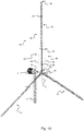


Classifications
-
- F—MECHANICAL ENGINEERING; LIGHTING; HEATING; WEAPONS; BLASTING
- F03—MACHINES OR ENGINES FOR LIQUIDS; WIND, SPRING, OR WEIGHT MOTORS; PRODUCING MECHANICAL POWER OR A REACTIVE PROPULSIVE THRUST, NOT OTHERWISE PROVIDED FOR
- F03D—WIND MOTORS
- F03D1/00—Wind motors with rotation axis substantially parallel to the air flow entering the rotor
- F03D1/06—Rotors
- F03D1/0608—Rotors characterised by their aerodynamic shape
- F03D1/0625—Rotors characterised by their aerodynamic shape of the whole rotor, i.e. form features of the rotor unit
-
- F—MECHANICAL ENGINEERING; LIGHTING; HEATING; WEAPONS; BLASTING
- F03—MACHINES OR ENGINES FOR LIQUIDS; WIND, SPRING, OR WEIGHT MOTORS; PRODUCING MECHANICAL POWER OR A REACTIVE PROPULSIVE THRUST, NOT OTHERWISE PROVIDED FOR
- F03D—WIND MOTORS
- F03D7/00—Controlling wind motors
- F03D7/02—Controlling wind motors the wind motors having rotation axis substantially parallel to the air flow entering the rotor
- F03D7/022—Adjusting aerodynamic properties of the blades
- F03D7/0224—Adjusting blade pitch
-
- F—MECHANICAL ENGINEERING; LIGHTING; HEATING; WEAPONS; BLASTING
- F03—MACHINES OR ENGINES FOR LIQUIDS; WIND, SPRING, OR WEIGHT MOTORS; PRODUCING MECHANICAL POWER OR A REACTIVE PROPULSIVE THRUST, NOT OTHERWISE PROVIDED FOR
- F03D—WIND MOTORS
- F03D1/00—Wind motors with rotation axis substantially parallel to the air flow entering the rotor
- F03D1/06—Rotors
- F03D1/0608—Rotors characterised by their aerodynamic shape
-
- F—MECHANICAL ENGINEERING; LIGHTING; HEATING; WEAPONS; BLASTING
- F03—MACHINES OR ENGINES FOR LIQUIDS; WIND, SPRING, OR WEIGHT MOTORS; PRODUCING MECHANICAL POWER OR A REACTIVE PROPULSIVE THRUST, NOT OTHERWISE PROVIDED FOR
- F03D—WIND MOTORS
- F03D1/00—Wind motors with rotation axis substantially parallel to the air flow entering the rotor
- F03D1/06—Rotors
- F03D1/065—Rotors characterised by their construction elements
- F03D1/0658—Arrangements for fixing wind-engaging parts to a hub
-
- F—MECHANICAL ENGINEERING; LIGHTING; HEATING; WEAPONS; BLASTING
- F03—MACHINES OR ENGINES FOR LIQUIDS; WIND, SPRING, OR WEIGHT MOTORS; PRODUCING MECHANICAL POWER OR A REACTIVE PROPULSIVE THRUST, NOT OTHERWISE PROVIDED FOR
- F03D—WIND MOTORS
- F03D1/00—Wind motors with rotation axis substantially parallel to the air flow entering the rotor
- F03D1/06—Rotors
- F03D1/065—Rotors characterised by their construction elements
- F03D1/0675—Rotors characterised by their construction elements of the blades
-
- F—MECHANICAL ENGINEERING; LIGHTING; HEATING; WEAPONS; BLASTING
- F05—INDEXING SCHEMES RELATING TO ENGINES OR PUMPS IN VARIOUS SUBCLASSES OF CLASSES F01-F04
- F05B—INDEXING SCHEME RELATING TO WIND, SPRING, WEIGHT, INERTIA OR LIKE MOTORS, TO MACHINES OR ENGINES FOR LIQUIDS COVERED BY SUBCLASSES F03B, F03D AND F03G
- F05B2240/00—Components
- F05B2240/20—Rotors
- F05B2240/30—Characteristics of rotor blades, i.e. of any element transforming dynamic fluid energy to or from rotational energy and being attached to a rotor
-
- F—MECHANICAL ENGINEERING; LIGHTING; HEATING; WEAPONS; BLASTING
- F05—INDEXING SCHEMES RELATING TO ENGINES OR PUMPS IN VARIOUS SUBCLASSES OF CLASSES F01-F04
- F05B—INDEXING SCHEME RELATING TO WIND, SPRING, WEIGHT, INERTIA OR LIKE MOTORS, TO MACHINES OR ENGINES FOR LIQUIDS COVERED BY SUBCLASSES F03B, F03D AND F03G
- F05B2240/00—Components
- F05B2240/20—Rotors
- F05B2240/30—Characteristics of rotor blades, i.e. of any element transforming dynamic fluid energy to or from rotational energy and being attached to a rotor
- F05B2240/302—Segmented or sectional blades
-
- F—MECHANICAL ENGINEERING; LIGHTING; HEATING; WEAPONS; BLASTING
- F05—INDEXING SCHEMES RELATING TO ENGINES OR PUMPS IN VARIOUS SUBCLASSES OF CLASSES F01-F04
- F05B—INDEXING SCHEME RELATING TO WIND, SPRING, WEIGHT, INERTIA OR LIKE MOTORS, TO MACHINES OR ENGINES FOR LIQUIDS COVERED BY SUBCLASSES F03B, F03D AND F03G
- F05B2260/00—Function
- F05B2260/70—Adjusting of angle of incidence or attack of rotating blades
- F05B2260/79—Bearing, support or actuation arrangements therefor
-
- Y—GENERAL TAGGING OF NEW TECHNOLOGICAL DEVELOPMENTS; GENERAL TAGGING OF CROSS-SECTIONAL TECHNOLOGIES SPANNING OVER SEVERAL SECTIONS OF THE IPC; TECHNICAL SUBJECTS COVERED BY FORMER USPC CROSS-REFERENCE ART COLLECTIONS [XRACs] AND DIGESTS
- Y02—TECHNOLOGIES OR APPLICATIONS FOR MITIGATION OR ADAPTATION AGAINST CLIMATE CHANGE
- Y02E—REDUCTION OF GREENHOUSE GAS [GHG] EMISSIONS, RELATED TO ENERGY GENERATION, TRANSMISSION OR DISTRIBUTION
- Y02E10/00—Energy generation through renewable energy sources
- Y02E10/70—Wind energy
- Y02E10/72—Wind turbines with rotation axis in wind direction
Definitions
- the invention relates to a wind turbine, more specifically to a rotor assembly for a wind turbine.
- Wind turbines are often used to generate electrical energy from electrical energy by converting the kinetic energy of the wind.
- a wind turbine comprising a horizontal shaft comprises a tower, a stator and a rotor assembly with a plurality of vanes.
- the rotor assembly is mounted in the pod by means of a shaft which is directly or indirectly connected to a generator for generating electrical energy.
- a known wind turbine is described in US2009/0208337 , which discloses a wind turbine with a rotor assembly.
- Said rotor assembly comprises a central hub with a central rotation axis and a plurality of vanes, each of which is attached to the central hub by its central end and the longitudinal axis of which extends substantially radially with respect to the central rotation axis up to their radial end.
- the vanes comprise a two-part structure with an intermediate point situated between the central end and the radial end.
- the vanes comprise a central vane part which extends from the central end to this intermediate point.
- the vanes also comprise a radial vane part which is attached to the central vane part and extends from the intermediate point to the radial end of the vane.
- this rotor assembly comprises a cable system which cooperates with the vanes and the central hub.
- Both vane parts have a wing shape and particularly the wing shape of the central vane part results in a risk of interference with the cable system, in particular the pair of cables of each vane which is situated between the intermediate point and the central hub.
- the intermediate points of the various vanes are also connected to each other by means of a cable. This connection causes undesirable peak loads resulting from interference of deformations and vibrations of the various vanes in the plane of rotation of the vanes.
- FIG. 1 Another such wind turbine is known from CN101235795B , which discloses a wind turbine with a rotor assembly comprising a central hub 1, with a tapered pipe flange Z from which vanes extend radially comprising a two-part structure as explained above with a central vane part A and a radial vane part B attached at an intermediate point C1.
- Each of these vane parts A and B is shaped as a wing.
- the intermediate points of the various vanes are also connected to each other by means of a big ring C shown in figure 1 in dot striped lines. This increases the complexity and the weight of the rotor assembly.
- the cable system of CN101235795B comprises three cables 2, 3, 4 per vane. These cables being attached between vane attachment points at the intermediate point C1 and hub attachment points at the location of the central hub 1 and its tapered pipe flange Z. These three cables 2, 3, 4 are aligned with the longitudinal axis of their vane, viewed along the central rotation axis. Two of these three cables 3, 4 are on either side of the plane covered by the longitudinal axis of their vane.
- tapered pipe flange Z and the third cable attached increases complexity of the construction of the central hub 1, and further more when used in an off-wind setup in which the rotor assembly is situated downstream of the mast along the wind direction during operation, cable 4 is the one exposed to the highest load as it is exposed to a tension load, while the cables 2 and 3 are exposed to a pressure load which reduces the load in these cables.
- a rotor assembly for a wind turbine which overcomes the abovementioned drawbacks and more particularly a rotor assembly for a wind turbine comprising vanes with an improved cable system so that the vanes can be made in a simpler manner and so as to be more lightweight and with a reduced risk of the cable system interfering with the wing shape of the vane or of undesirable vibrations occurring due to interference of various vanes in the cable system. Additionally there is a need for an improved manufacturing process for wings suitable for use in such wind turbines.
- rotor assembly for a wind turbine comprising,
- the rotor assembly according to the invention allows the surface covered by the wing shape to be increased in which the specific geometry of the cable system allows for a simple and lightweight construction of the vanes. This is achieved by a specific construction of the rotor assembly in which the cable system optimally reduces the load on the central vane part.
- vibrations and deformations of individual vanes are no longer passed on to the other vanes, so that undesirable peak loads due to interference of such phenomena are avoided.
- this offers the possibility of limiting the maximum length of the individual components of the rotor assembly, which is advantageous during transportation.
- the rotor assembly does not comprise any further elements forming a direct structural connection between two of said plurality of vanes at a location other than their central end.
- each of the vanes is isolated from each other in a way that peak loads which could result from opposing deformations of the individual vanes in the plane of rotation of the longitudinal axis of the vanes are prevented.
- the distance from the longitudinal axis of the vane to the vane attachment points is smaller than the distance from the longitudinal axis of the vane to the hub attachment points.
- the central vane part comprises a tube extending along the longitudinal axis of the vane; and the radial vane part comprises a tube extending along the longitudinal axis of the vane, the tube of the radial vane part being adapted to be fitted to the tube of the central vane part.
- the tube of the radial vane part is fitted to the tube of the central vane part at the location of the intermediate point.
- the wing is rotatably attached to the tube of the radial vane part.
- the wing comprises an internal cavity, extending along the longitudinal axis of the vane, into which the tube of the radial vane part can be introduced, such that said wing is rotatably attached to the tube of the radial vane part.
- the central vane part comprises a tube.
- the radial vane part comprises a tube which can be fitted to the tube of the central vane part at the location of the intermediate point and to which the wing is attached.
- the wing is rotatably attached to the tube of the radial vane part.
- the wing along the longitudinal axis of the vane, comprises an internal cavity into which the tube of the radial vane part can be introduced.
- both cables are attached at vane attachment points at an intermediate attachment location in between the intermediate point and the radial end.
- the vane attachment points are located on the tube of the radial vane part: and the wing comprises for each of the cables an opening through which the cable extends to the vane attachment point, the opening being dimensioned such that it allows for a predetermined degree of rotation of the wing.
- at least one of the cables is attached to the tube of the radial vane part by means of a vane attachment connector adapted to interact with the opening such that the degree of rotation of the wing is limited to the predetermined degree of rotation of the wing.
- both cables are attached at vane attachment points at the location of the intermediate point.
- the vane attachment points are located on one of the tubes at a location which is not covered by the wing.
- Such a location for the vane attachment points is advantageous as it provides for attachment points that inherently limit the possibility of interference with the wing and can be provided in a simple way.
- the central vane part has a length in the range of 20% to 200% of the length of the radial vane part, for example in the range of 40% to 150%, preferably 45% to 100%, for example 50%.
- Such a range of relative lengths allows for a suitable reduction of the length of the vane when the vane parts are in their disconnected state, which is advantageous during transportation of the rotor assembly.
- the vane comprises a positioning mechanism and a control device which is coupled thereto and which, upon activation, is configured to adjust the position of the wing; and the wing is formed and/or fitted in such a way that the wing turns out of the wind upon deactivation of the control device.
- the positioning mechanism and the control device coupled thereto are configured such that they turn the wing out of the wind when a predetermined speed of rotation of the rotor assembly is exceeded.
- the positioning mechanism comprises a hydraulic actuator and the control device which is coupled thereto comprises a hydraulic circuit.
- the positioning mechanism and/or the control device coupled thereto are fitted in the rotor assembly, the control device further comprising:
- the wing is produced as an extruded profile.
- the rotor assembly according to the invention can use a wing which is simple to produce.
- a non-claimed method of manufacturing a wing for use in a rotor assembly in which the wing is produced as a twisted extruded profile, that is twisted about its longitudinal axis said twisted extruded profile has a degree of twist per meter of length of the wing in the range of 0,5° to 5°, for example 3°, characterised in that, the twisted extruded profile is manufactured by means of an extrusion process making use of a twisted extrusion die channel with predetermined degree of twist per meter of length of the die channel along its longitudinal axis, in the range of 1° to 5°, for example 3°.
- a wing can be manufactured allowing for a rotor assembly with an increased wind energy conversion efficiency, by means of an advantageous manufacturing process without increasing complexity of the manufacturing process as only a suitably constructed die channel needs to be fitted to the extruder, which will result in in a more uniform degree of twist along the longitudinal axis when compared with an extrusion process using a rotatable dye as there is no longer a risk for variations in the extraction speed of the extruded profile versus the rotational speed of the die.
- the degree of twist is solely determined by the twisted shape of the die and will thus be substantially uniform along the entire length of the extruded wing.
- a wind turbine comprising a rotor assembly according to the first aspect of the invention, characterized in that the wind turbine furthermore comprises:
- the bearing system comprises at least two bearings, the rotation axis of which coincides with the essentially vertical rotation axis and which are fitted at various locations along the essentially vertical longitudinal axis of the mast.
- the bearings of the bearing system are conical bearings.
- the bearing system comprises one or more slewing bearings.
- Such a construction makes it possible to absorb both the radial and the axial load of the pod on the mast in an efficient manner without the need for a bearing with a large diameter.
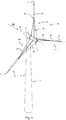
- Figure 1 shows an embodiment comprising a wind turbine 1 with a rotor assembly 10 according to the invention. It relates to a horizontal-axis wind turbine 1 comprising a pod 3 which is fitted so as to be rotatable about an essentially vertical rotation axis on a mast or tower 2.
- the rotor assembly 10 itself is rotatably fitted in the pod to rotate about an essentially horizontal central rotation axis R.
- the rotor assembly 10 is arranged "downwind", meaning according to the wind direction W at the back of the pod 3 during operation.
- Such an arrangement has the advantage that no additional mechanism is necessary to keep the rotor assembly 10 in the wind.
- the rotor assembly 10 can also be arranged "upwind", for example in order to prevent the disadvantageous effects of the turbulence at the rear of the tower, but this requires an additional mechanism in order to keep the rotor assembly in the wind, such as for example a weather vane or a wind sensor in combination with a servomotor.
- the rotor assembly 10 is rotatable about an essentially central horizontal rotation axis R and comprises a central hub 12, the central axis of which coincides with the central horizontal rotation axis R.
- Three vanes 14 are attached to this central hub. It is clear that, according to alternative embodiments, a different plurality of vanes may be fitted, such as for example two, four, five, ....
- the vanes 14 are attached to the central hub 12 by their central end 22 and extend along their longitudinal axis L, essentially radially with respect to the central rotation axis R, up to their radial end 32.
- these vanes 14 each comprise an intermediate point 42 situated between the first central end 22 and the second radial end 32.
- the vane 14 is divided into two vane parts 20, 30, that is to say that the vane 14 comprises a central vane part 20 which extends from the first central end 22 to the intermediate point 42.
- a first central vane part 20 which according to this embodiment is configured as a tube 24
- a second radial vane part 30 is then attached to this first central vane part 20, which according to this embodiment is configured as a tube 24.
- This radial vane part 30 extends from the intermediate point 42 to the second radial end 32.
- the longitudinal axes L of the two vane parts 20, 30 virtually converge here.
- this second radial vane part 30 consists of a tube 34 which is attached to the tube 24 of the first central vane part 20 at the location of the intermediate point 42.
- a wing 35 which is shaped such that it can be driven by the wind is fitted around this tube 34 of the radial vane part 30.
- This wing 35 may be fixedly attached to this tube 34, but according to a preferred embodiment this wing 35 is rotatably mounted on this tube 34 so that it can be turned to different positions by means of an actuator 72, as will be discussed below with reference to Figures 4A-C .
- Separating the vane 14 into two parts is advantageous because in this way the vane 14 can be more readily transported in the disassembled state.
- this also makes it possible to produce the wing 35 using a profile which is easy to produce, for example an aluminium or plastic extruded profile.
- FIG. 4A-C An embodiment of such a profile for the wing 35 is illustrated, for example, in Figures 4A-C , in which the wing 35 comprises an internal cavity 38 along the longitudinal axis L of the vane 14 into which the tube 34 of the second radial vane part 30 can be introduced.
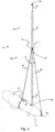
- each of these vanes 14 also comprises a cable system 60 which cooperates with the vane 14 and the central hub 12.
- This cable system 60 ensures that deformation of the vane 14 is counteracted. This deformation relates to deformation by load on the vanes 14 along the direction of the central rotation axis R.
- the cable system 60 contains one single pair of cables per vane 14 comprising a first cable 62 and a second cable 64. These two cables 62, 64 are in each case attached between attachment points 16, 17 at the location of the intermediate point 42 and attachment points 18, 19 at the location of the central hub 12. As can be seen, these two cables 62, 64 are aligned with the longitudinal axis L of their vane 14, viewed along the central rotation axis R.
- These two cables 62, 64 are furthermore also on either side of the plane which is covered by the longitudinal axis L of their vane 14.
- one of the cables 62 of the pair of cables is fitted "upwind”, while the other cable 64 of the pair of cables is fitted downwind.
- Both cables of the pair of cables are thus situated on either side of the plane which is covered by the longitudinal axis L of the vane 14 during a rotation about the central rotation axis R.
- the attachment points 16, 17 are arranged on the tube 24 of the central vane part 20, at the location of the intermediate point 42.
- the attachment points may be arranged on, for example, the tube 34 of the radial vane part 30 in a similar way near the longitudinal axis L. In this case, it is important that the distance from the longitudinal axis L of the vane 14 to the attachment points 16, 17 is smaller than the distance d1 from the longitudinal axis L to the corresponding attachment points 18, 19. Consequently, both cables 62, 64 form an angle A1.
- the cables are provided with known cable tensioners at the location of the attachment points 16, 17, 18 and/or 19 in order to be able to adjust the tension of the cables 62, 64 in such a way as to provide the desired stiffness to the central vane part 20, without requiring complicated profiles for the tube 24 or materials having a very high degree of stiffness.
- the tube 24 may, for example, be made from a suitable metal, such as for example steel or aluminium. In this way, a simple and lightweight construction of this central vane part 20 is made possible.
- the length L2 of the radial vane part 30 and the length L1 of the central vane part 20 remain within certain legal limits.
- the length L1 and L2 may be, for example, approximately 6 or 12 metres, so that they can be transported by means of standard containers.
- the cable system 60 comprising a pair of cables with two cables 62, 64 per vane 14 as described above also gives optimum results with regard to minimizing additional air resistance of the rotor assembly 10, as more cables or additional elements, such as for example spreaders for the cables, in each case cause additional air resistance.
- possible interference with the wing 35 is prevented as the pair of cables is arranged between the intermediate point 42 and the central hub 12.
- the wing 35 is fitted in a fixed position, for example fixed on the tube 34, then the components of the vane 14 have to be dimensioned in such a manner that they can withstand the highest possible load which can be caused by the wind.
- the wing 35 along the longitudinal axis L of the vane 14 is to this end provided with an internal cavity 38 into which the tube 34 of the second radial vane part 30 can be introduced, and to which the wing 35 is rotatably attached by means of a suitable bearing.
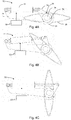
- the positioning mechanism 70 is configured as a hydraulic actuator 72, for example a single-acting hydraulic actuator 72 with built-in return spring, but according to alternative embodiments this may also be an electric, pneumatic or any other suitable type of actuator.
- the hydraulic actuator 72 is connected to the tube 34 of the radial vane part 30 via an arm 76, which is arranged, for example, at the location of the intermediate point 42.
- the actuator 72 is connected to the wing 35 via an arm 74. The actuator 72 is thus able to determine the position of the wing 35 which is fitted to the tube 34 of the radial vane part 30 so as to be rotatable by means of a bearing 78.
- Figure 4B shows the wing 35 in its starting position. In this position, the wind has a sufficiently great impact on the wing 35 so that sufficient torque can be generated to be able to set the rotor assembly 10 in motion from a standstill.
- the wing 35 is at a well-defined angle of incidence with respect to the relative wind direction. This angle of incidence of the wind direction ensures that a starting torque is generated which is as large as possible.
- FIG. 4C shows the wing 35 in a position which is assumed upon deactivation of the wind turbine, for example in order to prevent overloading at excessive wind speeds or for maintenance purposes. In this position, the wing 35 is substantially aligned with the wind direction, so that the torque generated by the rotor assembly 10 is reduced.
- the wing 35 is shaped in such a way that, or is provided with means, such as springs, actuators or other elements which ensure that, upon deactivation of the control device 80, the wing 35 is turned out of the wind, they assume the position as illustrated in Figure 4C .
- the wing 35 is also turned to the position illustrated in Figure 4C in order to prevent overloading of the rotor assembly 10.
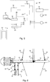
- FIG. 5 shows an embodiment of a control device 80 for the actuator 72 illustrated in Figures 4A-C .
- This control device 80 comprises, for example, a hydraulic circuit 84, 85, 86 with hydraulic components, optionally supplemented by an electronic processing unit 81 and suitable energy supplies and/or energy sources 82, 86. Furthermore, the control device is coupled to suitable sensors 88, 89 in order, for example, to determine the speed of rotation of the rotor assembly 10 or the position of the wings 35.
- the hydraulic circuit 84, 85, 86 is actuated in such a way by the electronic processing unit 81 that the position of the actuator 72 is controlled depending on the speed of rotation of the rotor assembly 10 or on the basis of settings by an operator, for example to make it possible to carry out maintenance on the wind turbine 1.
- the hydraulic circuit comprises a suitable energy source 86 with a supply of hydraulic liquid, such as a hydraulic pressure vessel or an accumulator combined with, for example, a suitable hydraulic pump which is able to supply the hydraulic liquid to or discharge it from the actuator 72.
- the hydraulic circuit comprises, for example, a centrifugal valve 84 which, depending on the speed of rotation of the rotor assembly 10, actuates the actuator 72 when the maximum permissible speed of rotation is exceeded to deactivate the wings 35 by moving them to the position illustrated in Figure 4C .
- the hydraulic circuit also comprises an electrically actuated valve 85.
- This valve 85 is actuated in such a manner that hydraulic liquid is supplied to or discharged from the actuator 72, so that the actuator 72 moves the wing 35 into the desired position or keeps it in the desired position.
- the valve 35 is actuated by an electronic processing unit 81 which, for example, will automatically determine the correct position of the actuator 72 by means of valve 85, on the basis of the data from sensors, such as for example an angular rotation sensor 88 which detects the position of the wing 35 and an angular rotation sensor 89 which records the speed of rotation of the rotor assembly 10.
- the electronic processing unit 81 may also be actuated by means of instructions from an operator, for example to deactivate the wings 35 so that the rotor assembly 10 can easily be brought to a standstill in order to facilitate maintenance operations.
- the electronic processing unit 81 is provided with current by means of an electrical energy supply 82, such as for example a suitable battery or a capacitor. This electrical energy supply 82 may in turn supply energy to the hydraulic energy source 86, for example to the hydraulic pump.
- the positioning mechanism 70 not only the positioning mechanism 70, but also the control device 80 which is coupled thereto is arranged in the rotor assembly 10.
- the control device 80 which is coupled thereto is arranged in the rotor assembly 10.
- all the necessary means for the operation of the positioning mechanism 70 are also fitted to the rotor assembly 10, for example in the wing 35 or on the vane 14 or in the central hub 12.
- the electrical energy supply 82 will rotate along with the rotor assembly 10. In order to charge this energy supply 82, it is then possible, for example, to use wireless energy transfer.
- the energy supply 82 can be charged by means of a dynamo or alternator or another suitable electric generator which is also fitted in the rotor assembly.
- the electric generator is arranged in the rotor assembly in such a manner that the rotation of the rotor assembly 10 is converted into a rotation of the electric generator in order to thus generate electrical energy which can be added to the electrical energy supply 82.
- This may, for example, be achieved by fitting the stator of the electric generator in the rotor assembly 10 and by coupling the rotor of the electric generator to the pod 3, so that, during the rotation of the rotor assembly 10, the rotor of the electric generator rotates with respect to its stator which moves concomitantly with the rotor assembly 10.
- control device 80 which is present in the rotor assembly 10
- other control devices 90 which are fitted in a stationary manner, for example a control device of the wind turbine which is present in the tower 2 or the pod 3 or a service terminal for use by an operator
- known systems for wireless data communication can be used.
- control device 80 which is arranged in the rotor assembly comprises a wireless communication module 83, for example a Wi-Fi, mobile, Bluetooth or other suitable module which enables wireless communication with a stationary control device 90.
- a wireless communication module 83 for example a Wi-Fi, mobile, Bluetooth or other suitable module which enables wireless communication with a stationary control device 90.
- FIG. 6 A variant embodiment of the wind turbine 1 according to the invention is illustrated in Figure 6 .
- the rotor assembly 10 essentially corresponds to the embodiment illustrated in Figures 1 - 3 .
- the partial cross section from Figure 6 furthermore shows how the pod 3, to which the rotor assembly 10 is fitted so as to be able to rotate along the essentially horizontal rotation axis R, is itself fitted to the mast so as to be able to rotate.
- the pod 3 On the mast 2 which has an essentially vertical longitudinal axis, the pod 3 is fitted so as to be able to rotate along an essentially vertical rotation axis by means of a bearing system 50.
- this bearing system 50 comprises two bearings 52, 54 whose axes of rotation coincide with the essentially vertical rotation axis.
- bearings 52, 54 are arranged at various locations along the essentially vertical longitudinal axis of the mast 2.
- These bearings 52, 54 of the bearing system 50 are for example conical bearings, since such a bearing system 50 is able to absorb the radial and axial load in an efficient manner without requiring bearings of a large diameter.
- one or more other suitable bearings could be provided, such as for example one or more suitable slewing bearings of sufficient capacity.
- a pod-positioning mechanism 56 is also illustrated and consists of an actuator, for example an electrical or hydraulic actuator which cooperates with the mast 2 and the pod 3 and which can be actuated, for example, by means of a suitable control device for bringing the pod 3 and consequently also the rotor assembly 10 into a suitable position with respect to the wind direction.
- an actuator for example an electrical or hydraulic actuator which cooperates with the mast 2 and the pod 3 and which can be actuated, for example, by means of a suitable control device for bringing the pod 3 and consequently also the rotor assembly 10 into a suitable position with respect to the wind direction.
- the embodiment of the wing 35 described above with reference to for example Figures 4A-4C comprises a straight linear extruded profile.
- the wing 35 which extends along a longitudinal axis L between a central end 351 and a radial end 352 comprises an upstream end 353 and a downstream end 354 which both run parallel to the longitudinal axis L, this longitudinal axis L forming for example the central axis of the internal cavity 38 of the wing 35.
- wing 35 is simple of construction an improved efficiency of conversion of the wind energy can be attained when such a wing 35 comprises a longitudinal twisted shape, this means as shown in Figure 7 , that the wing 35 along its longitudinal axis L is provided with a predetermined degree of twist per meter of length of the wing 35, this means with a predetermined ratio between the angle of rotation 35T about the longitudinal axis L between the central end 351 and the radial end 352 and the length of the wing 35L.
- the length 35L of the wing 35 is for example about 6m and the angle of rotation 35T is about 20°.
- a wing 35 with a twisted extruded profile as shown in Figure 8 of which the central axis 351W, 352W along the width 35W of the wing 35, which is for example 35cm, is rotated about 20° between the central end 351 and the radial end 352.
- the wing 35 can be produced as a twisted extruded profil, that is twisted about its longitudinal axis (L), as long as in general said twisted extruded profile has a degree of twist per meter of length of the wing 35 in the range of 1° to 5°, for example 3°, 4°, etc..
- the twisted extruded profile of the wing 35 is manufactured by means of an extrusion process making use of a twisted extrusion die channel with predetermined degree of twist per meter of length of the die channel along its longitudinal axis, in the range of 1° to 5°, for example 3° as this enables a uniform degree of twist along the entire length of the wing 35 which can be realised without modifying anything to the conventional extrusion process for manufacturing a straight extruded profile wing but the die channel.
- wing 35 is possible as long as they allow for manufacturing by means of an extrusion process as described above and preferably their cross section comprises an internal cavity 38 along the longitudinal axis L suitable for introducing a tube of a vane such as for example shown in Figure 9 , as will be explained in more detail below.
- Figure 10 shows a wind turbine comprising a rotor assembly with vanes according to the embodiment shown in Figure 9 .
- the construction of this embodiment is largely similar to that of the embodiments described above and similar elements have been identified with the same reference signs.
- the main difference with the embodiment of Figures 1-3 is that both cables 62, 64 are now attached at vane attachment points 16, 17 at an intermediate attachment location 43 in between the intermediate point 42 and the radial end 32.
- the vane attachment point 16, 17 at the intermediate attachment location 43 are located on the tube 34 of the radial vane part 30.
- each vane 14 comprises two vane attachment connector 66, 68 that attach the two cables 62, 64 to the tube 34 of the radial vane part 30 at the intermediate attachment location 43.
- these vane attachment connectors 66, 68 extend at opposite sides of the tube 34, substantially transverse to the longitudinal axis L of the tube 34 through the respective openings 36, 37 in the wing 35. From these attachment connectors 66, 68 form a vane attachment point 16, 17 for the corresponding cables 62, 64 which then extend to their hub attachment point 18, 19. It is clear that such as best shown in Figure 13 , in this way the attachment connectors 66, 68 interact with their corresponding opening 36, 37 in such a way that the range of rotation of the wing 35 is limited to a predetermined desired range of rotation of the wing 35 around the longitudinal axis L, as when these limits are reached the attachment connectors form an abutment for the side of the circumference of their opening.
- any other suitable element of the cable system such as for example the cables 62, 64 themselves could extend through the corresponding opening to the intermediate attachment location 43 and interact with the corresponding opening in substantially the same way as described above for limiting the range of rotation of the wing 35 to the predetermined desired range of rotation.
- Figure 14 shows the embodiment of the vane 14 of Figures 10-13 without the wing being present for more clearly showing the radial tube 34 which is to be inserted in the internal cavity 38 of the wing 35 when mounted.
- the tube 24 of the central vane part 20 comprises two reinforcement ribs that extend generally transvers to the plane of both cables 62, 64 and provide additional rigidity against forces transverse to plane of the cables 62, 64.
- the a spreader 35 is provided at the intermediate point 42 that extends transverse to the longitudinal axis of the vane 14 and provides further vane attachment points for the cables 62, 64 at the intermediate point 42, such that the position of the cables 62, 64; especially in the vicinity of the wing 35 is securely determined.
- the central vane part 20 has a length in the range of 30% to 300% of the length of the radial vane part 30, for example in the range of 50% to 200%, preferably 75% to 150%, such as for example approximately the same size.
- the cable system 60 comprises only one single pair of cables 62, 64 per vane 14, both cables 62, 64 of which are attached between vane attachment points 16, 17 at the location between the central end 22 and the radial end 32 and hub attachment points 18, 19 at the location of the central hub 12, both these cables 62, 64 being fitted in such a manner that they are aligned with the longitudinal axis L of their vane 14, viewed along the central rotation axis R; and they are both on either side of the plane covered by the longitudinal axis L of their vane 14.
- cables 62, 64 in use in the cable system 60 could be formed as cables comprising two or more wires running side by side and bonded, twisted, or braided together to form a single assembly.
- the cables 62, 64 could alternatively also be formed as cable like elongate links, such as for example suitable elongate rod or bar. These cable like elongate links generally comprise a higher stiffness along their longitudinal direction, which reduces the level of pre-tensioning to be provided to the cable system 62, 64.
- the cables 62, 64 could be formed as a continuous cable extending from its vane attachment point 16, 17 to its hub attachment point 18, 19, but according to alternative embodiments, could also comprise a suitable sequence of a plurality of sequentially connected cable portions 62A, 62B, 64A, 64B, as for example schematically shown in Figure 14 in which the cables 62, 64 each comprise two sequentially connected rods which are connected at the location of the spreader 65. It is clear that further alternative embodiments are possible in which two more more cable portions are sequentially connected for forming the cable as long as the longitudinal axis of each of the cable portions substantially coincides with that of the entire cable.
Landscapes
- Engineering & Computer Science (AREA)
- Life Sciences & Earth Sciences (AREA)
- Sustainable Development (AREA)
- Sustainable Energy (AREA)
- Chemical & Material Sciences (AREA)
- Combustion & Propulsion (AREA)
- Mechanical Engineering (AREA)
- General Engineering & Computer Science (AREA)
- Physics & Mathematics (AREA)
- Fluid Mechanics (AREA)
- Wind Motors (AREA)
Description
- The invention relates to a wind turbine, more specifically to a rotor assembly for a wind turbine.
- Wind turbines are often used to generate electrical energy from electrical energy by converting the kinetic energy of the wind. A wind turbine comprising a horizontal shaft comprises a tower, a stator and a rotor assembly with a plurality of vanes. The rotor assembly is mounted in the pod by means of a shaft which is directly or indirectly connected to a generator for generating electrical energy.
- A known wind turbine is described in
US2009/0208337 , which discloses a wind turbine with a rotor assembly. Said rotor assembly comprises a central hub with a central rotation axis and a plurality of vanes, each of which is attached to the central hub by its central end and the longitudinal axis of which extends substantially radially with respect to the central rotation axis up to their radial end. The vanes comprise a two-part structure with an intermediate point situated between the central end and the radial end. The vanes comprise a central vane part which extends from the central end to this intermediate point. Furthermore, the vanes also comprise a radial vane part which is attached to the central vane part and extends from the intermediate point to the radial end of the vane. Furthermore, this rotor assembly comprises a cable system which cooperates with the vanes and the central hub. Both vane parts have a wing shape and particularly the wing shape of the central vane part results in a risk of interference with the cable system, in particular the pair of cables of each vane which is situated between the intermediate point and the central hub. In addition, the intermediate points of the various vanes are also connected to each other by means of a cable. This connection causes undesirable peak loads resulting from interference of deformations and vibrations of the various vanes in the plane of rotation of the vanes. - Another such wind turbine is known from
CN101235795B , which discloses a wind turbine with a rotor assembly comprising acentral hub 1, with a tapered pipe flange Z from which vanes extend radially comprising a two-part structure as explained above with a central vane part A and a radial vane part B attached at an intermediate point C1. Each of these vane parts A and B is shaped as a wing. In addition, the intermediate points of the various vanes are also connected to each other by means of a big ring C shown infigure 1 in dot striped lines. This increases the complexity and the weight of the rotor assembly. This connection also causes undesirable peak load resulting from interference of deformations and vibrations of the various vanes in the plane of rotation of the vanes. The cable system ofCN101235795B comprises threecables central hub 1 and its tapered pipe flange Z. These threecables cables 3, 4 are on either side of the plane covered by the longitudinal axis of their vane. The tapered pipe flange Z and the third cable attached increases complexity of the construction of thecentral hub 1, and further more when used in an off-wind setup in which the rotor assembly is situated downstream of the mast along the wind direction during operation, cable 4 is the one exposed to the highest load as it is exposed to a tension load, while thecables - Another such wind turbine is known from
DE19606359 , this mechanism uses a linkage system of which the linkages are connected at one end to the rotor at approximately the same point where the vane is connected to the rotor; and the linkages are connected at their other end to the wing of the vane. This does not allow the use of a vane comprising a wing rotatable along the longitudinal axis of the vane. It further causes the risk of generating large torsional forces at the connection points of the vane and the linkage system. There are disclosed some embodiments of such a wind turbine inEP2112372 which comprise a pair of cables per vane. As disclosed inEP2112372 these vanes are only structurally interconnected via the central hub. According to some embodiments shown the pair of cables is attached to the vane between its central and radial end. - It is known from
WO13007359A1 - As a result thereof, there is a need for a rotor assembly for a wind turbine which overcomes the abovementioned drawbacks and more particularly a rotor assembly for a wind turbine comprising vanes with an improved cable system so that the vanes can be made in a simpler manner and so as to be more lightweight and with a reduced risk of the cable system interfering with the wing shape of the vane or of undesirable vibrations occurring due to interference of various vanes in the cable system. Additionally there is a need for an improved manufacturing process for wings suitable for use in such wind turbines.
- According to a first aspect of the invention, rotor assembly for a wind turbine comprising,
- a central hub with a central rotation axis; and
- a plurality of vanes, each attached to the central hub by its central end and each extending from its central end up to its radial end along a longitudinal axis substantially radially with respect to the central rotation axis, and each comprising:
- an intermediate point situated between the central end and the radial end;
- a central vane part which extends from the central end to the intermediate point;
- a radial vane part which is attached to the central vane part and extends from the intermediate point to the radial end of the vane; and
- a cable system which cooperates with the vane and the central hub, the cable system comprising a pair of cables per vane, both cables of which are attached between vane attachment points at the location between the central end and the radial end and hub attachment points at the location of the central hub, both these cables being fitted in such a manner that:
- both these cables are aligned with the longitudinal axis of their vane, viewed along the central rotation axis; and
- both these cables are on either side of the plane covered by the longitudinal axis of their vane,
- the plurality of vanes are only structurally interconnected via the central hub and the cable system consists of one single pair of cables per vane.
-
- only the radial vane part (30) comprises a wing (35) having a shape which is suitable to be driven by the wind;
- the central vane part (20) comprises a tube (24) extending along the longitudinal axis (L) of the vane (14); and the radial vane part (30) comprises a tube (34) extending along the longitudinal axis (L) of the vane (14), the tube (34) of the radial vane part (30) being adapted to be fitted to the tube (24) of the central vane part (20);
- the wing (35) is rotatably attached to the tube (34) of the radial vane part (30);
- the wing (35), comprises an internal cavity (38), extending along the longitudinal axis (L) of the vane (14), into which the tube (34) of the radial vane part (30) can be introduced, such that said wing (35) is rotatably attached to the tube (34) of the radial vane part (30);
- both cables (62, 64) are attached at vane attachment points (16, 17) at an intermediate attachment location (43) in between the intermediate point (42) and the radial end (32);
- the vane attachment points (16, 17) at the intermediate attachment location (43) are located on the tube (34) of the radial vane part (30); and
- the wing (35) comprises for each of the cables (62, 64) of its vane (14) an opening (36, 37) through which the cable system (60) extends to the intermediate attachment location (43), the opening (36, 37) being dimensioned such that it allows for a predetermined range of rotation of the wing (35) around the longitudinal axis (L).
- The rotor assembly according to the invention allows the surface covered by the wing shape to be increased in which the specific geometry of the cable system allows for a simple and lightweight construction of the vanes. This is achieved by a specific construction of the rotor assembly in which the cable system optimally reduces the load on the central vane part. In addition, vibrations and deformations of individual vanes are no longer passed on to the other vanes, so that undesirable peak loads due to interference of such phenomena are avoided. In addition, this offers the possibility of limiting the maximum length of the individual components of the rotor assembly, which is advantageous during transportation.
- It is clear that in this way the rotor assembly does not comprise any further elements forming a direct structural connection between two of said plurality of vanes at a location other than their central end.
- Thereby each of the vanes is isolated from each other in a way that peak loads which could result from opposing deformations of the individual vanes in the plane of rotation of the longitudinal axis of the vanes are prevented.
- Preferably, for each vane, the distance from the longitudinal axis of the vane to the vane attachment points is smaller than the distance from the longitudinal axis of the vane to the hub attachment points.
- In this way, deformations of the central vane part in the direction of the rotation axis of the rotor assembly can be absorbed efficiently, with a cable system that only has a minimal impact on air resistance of the rotor assembly.
- According to the invention, the central vane part comprises a tube extending along the longitudinal axis of the vane; and the radial vane part comprises a tube extending along the longitudinal axis of the vane, the tube of the radial vane part being adapted to be fitted to the tube of the central vane part.
- This makes it possible to produce the rotor assembly using components that are simple to produce.
- According to a further embodiment the tube of the radial vane part is fitted to the tube of the central vane part at the location of the intermediate point.
- In this way all mounting means for the cable system and the vane parts are located at approximately the same location along the longitudinal axis of the vane which facilitates the mounting operation.
- According to the invention, the wing is rotatably attached to the tube of the radial vane part.
- This allows for an optimized positioning of the wing depending on for example the wind speed and the rotational speed of the rotor assembly during use.
- According to the invention, the wing comprises an internal cavity, extending along the longitudinal axis of the vane, into which the tube of the radial vane part can be introduced, such that said wing is rotatably attached to the tube of the radial vane part.
- This allows for a simple and secure rotatable connection of the wing to the tube of the radial vane part.
- According to the invention, the central vane part comprises a tube. Preferably, the radial vane part comprises a tube which can be fitted to the tube of the central vane part at the location of the intermediate point and to which the wing is attached. According to another preferred embodiment, the wing is rotatably attached to the tube of the radial vane part. Preferably, the wing, along the longitudinal axis of the vane, comprises an internal cavity into which the tube of the radial vane part can be introduced.
- This makes it possible to produce the rotor assembly using components that are simple to produce.
- According to the invention, both cables are attached at vane attachment points at an intermediate attachment location in between the intermediate point and the radial end. The vane attachment points are located on the tube of the radial vane part: and the wing comprises for each of the cables an opening through which the cable extends to the vane attachment point, the opening being dimensioned such that it allows for a predetermined degree of rotation of the wing. Preferably at least one of the cables is attached to the tube of the radial vane part by means of a vane attachment connector adapted to interact with the opening such that the degree of rotation of the wing is limited to the predetermined degree of rotation of the wing.
- In this way interference of the wing with the cable system is minimized, while there is no longer a need for the use of additional stops or similar elements for limiting the range of rotational movement such that it does not exceed allowable limits during use.
- According to a non-claimed embodiment both cables are attached at vane attachment points at the location of the intermediate point. Preferably the vane attachment points are located on one of the tubes at a location which is not covered by the wing.
- Such a location for the vane attachment points is advantageous as it provides for attachment points that inherently limit the possibility of interference with the wing and can be provided in a simple way.
- Preferably the central vane part has a length in the range of 20% to 200% of the length of the radial vane part, for example in the range of 40% to 150%, preferably 45% to 100%, for example 50%.
- Such a range of relative lengths allows for a suitable reduction of the length of the vane when the vane parts are in their disconnected state, which is advantageous during transportation of the rotor assembly.
- Preferably, the vane comprises a positioning mechanism and a control device which is coupled thereto and which, upon activation, is configured to adjust the position of the wing; and the wing is formed and/or fitted in such a way that the wing turns out of the wind upon deactivation of the control device.
- According to an embodiment, the positioning mechanism and the control device coupled thereto are configured such that they turn the wing out of the wind when a predetermined speed of rotation of the rotor assembly is exceeded.
- This makes it possible to protect the rotor assembly against overload.
- According to an embodiment, the positioning mechanism comprises a hydraulic actuator and the control device which is coupled thereto comprises a hydraulic circuit.
- According to a further embodiment, the positioning mechanism and/or the control device coupled thereto are fitted in the rotor assembly, the control device further comprising:
- an energy supply which is configured to be charged by means of an electric generator which is fitted to the rotor assembly or by a stationary energy source by means of wireless transfer of energy; and/or
- a wireless communication module which is configured to make wireless communication possible between the control device and a stationary control device.
- This makes it possible to fit and actuate the actuators of the rotor assembly in a simple manner without complicated mechanical transmissions.
- According to an embodiment, the wing is produced as an extruded profile.
- In this way, the rotor assembly according to the invention can use a wing which is simple to produce.
- According to a second aspect, there is provided a non-claimed method of manufacturing a wing for use in a rotor assembly according to a first aspect of the invention, in which the wing is produced as a twisted extruded profile, that is twisted about its longitudinal axis said twisted extruded profile has a degree of twist per meter of length of the wing in the range of 0,5° to 5°, for example 3°, characterised in that, the twisted extruded profile is manufactured by means of an extrusion process making use of a twisted extrusion die channel with predetermined degree of twist per meter of length of the die channel along its longitudinal axis, in the range of 1° to 5°, for example 3°.
- In this way a wing can be manufactured allowing for a rotor assembly with an increased wind energy conversion efficiency, by means of an advantageous manufacturing process without increasing complexity of the manufacturing process as only a suitably constructed die channel needs to be fitted to the extruder, which will result in in a more uniform degree of twist along the longitudinal axis when compared with an extrusion process using a rotatable dye as there is no longer a risk for variations in the extraction speed of the extruded profile versus the rotational speed of the die. The degree of twist is solely determined by the twisted shape of the die and will thus be substantially uniform along the entire length of the extruded wing. Additionally such a twisted die channel will cause a more advantageous level and distribution of residual stresses within the extruded profile thus resulting in an extruded wing with advantageous mechanical properties for withstanding the stresses to which it will be subjected during operation in a rotor assembly of a windturbine.
- According to a third aspect of the invention there is provided a wind turbine comprising a rotor assembly according to the first aspect of the invention, characterized in that the wind turbine furthermore comprises:
- a pod to which the rotor assembly is attached so as to be rotatable along the essentially horizontal rotation axis;
- a mast having an essentially vertical longitudinal axis to which the pod is attached so as to be rotatable along an essentially vertical rotation axis by means of a bearing system.
- According to a further embodiment, the bearing system comprises at least two bearings, the rotation axis of which coincides with the essentially vertical rotation axis and which are fitted at various locations along the essentially vertical longitudinal axis of the mast. Optionally, the bearings of the bearing system are conical bearings. According to still further embodiments the bearing system comprises one or more slewing bearings.
- Such a construction makes it possible to absorb both the radial and the axial load of the pod on the mast in an efficient manner without the need for a bearing with a large diameter.
- The invention will now be described in more detail with reference to the figures in which:
-
Figure 1 shows an embodiment of a wind turbine according to the invention; -
Figures 2 and3 show a partial representation of the rotor assembly of the wind turbine fromFigure 1 ; -
Figures 4A-C and5 show an embodiment of a positioning mechanism for the vanes; -
Figure 6 diagrammatically shows a partial cross section of a variant embodiment of the wind turbine according to the invention; -
Figures 7 and 8 schematically show an embodiment of wing manufactured according to an advantageous manufacturing process; -
Figure 9 , shows a wing as shown inFigures 7 and 8 , in use in a vane of an embodiment of the rotor assembly as shown inFigures 10 - 16 ; and -
Figures 10-14 schematically show a further embodiment of the rotor assembly. -
Figure 1 shows an embodiment comprising awind turbine 1 with arotor assembly 10 according to the invention. It relates to a horizontal-axis wind turbine 1 comprising apod 3 which is fitted so as to be rotatable about an essentially vertical rotation axis on a mast ortower 2. Therotor assembly 10 itself is rotatably fitted in the pod to rotate about an essentially horizontal central rotation axis R. Therotor assembly 10 is arranged "downwind", meaning according to the wind direction W at the back of thepod 3 during operation. Such an arrangement has the advantage that no additional mechanism is necessary to keep therotor assembly 10 in the wind. According to an alternative embodiment, therotor assembly 10 can also be arranged "upwind", for example in order to prevent the disadvantageous effects of the turbulence at the rear of the tower, but this requires an additional mechanism in order to keep the rotor assembly in the wind, such as for example a weather vane or a wind sensor in combination with a servomotor. - The
rotor assembly 10 is rotatable about an essentially central horizontal rotation axis R and comprises acentral hub 12, the central axis of which coincides with the central horizontal rotation axis R. Threevanes 14 are attached to this central hub. It is clear that, according to alternative embodiments, a different plurality of vanes may be fitted, such as for example two, four, five, .... Thevanes 14 are attached to thecentral hub 12 by theircentral end 22 and extend along their longitudinal axis L, essentially radially with respect to the central rotation axis R, up to theirradial end 32. - As illustrated in
Figure 1 and also in more in detail inFigures 2 and3 , thesevanes 14 each comprise anintermediate point 42 situated between the firstcentral end 22 and the secondradial end 32. - The
vane 14 is divided into twovane parts vane 14 comprises acentral vane part 20 which extends from the firstcentral end 22 to theintermediate point 42. To this firstcentral vane part 20, which according to this embodiment is configured as atube 24, a secondradial vane part 30 is then attached. Thisradial vane part 30 extends from theintermediate point 42 to the secondradial end 32. The longitudinal axes L of the twovane parts radial vane part 30 consists of atube 34 which is attached to thetube 24 of the firstcentral vane part 20 at the location of theintermediate point 42. Awing 35 which is shaped such that it can be driven by the wind is fitted around thistube 34 of theradial vane part 30. Thiswing 35 may be fixedly attached to thistube 34, but according to a preferred embodiment thiswing 35 is rotatably mounted on thistube 34 so that it can be turned to different positions by means of anactuator 72, as will be discussed below with reference toFigures 4A-C . Separating thevane 14 into two parts is advantageous because in this way thevane 14 can be more readily transported in the disassembled state. In addition, this also makes it possible to produce thewing 35 using a profile which is easy to produce, for example an aluminium or plastic extruded profile. An embodiment of such a profile for thewing 35 is illustrated, for example, inFigures 4A-C , in which thewing 35 comprises aninternal cavity 38 along the longitudinal axis L of thevane 14 into which thetube 34 of the secondradial vane part 30 can be introduced. - In addition, each of these
vanes 14 also comprises acable system 60 which cooperates with thevane 14 and thecentral hub 12. Thiscable system 60 ensures that deformation of thevane 14 is counteracted. This deformation relates to deformation by load on thevanes 14 along the direction of the central rotation axis R. To this end, thecable system 60 contains one single pair of cables pervane 14 comprising afirst cable 62 and asecond cable 64. These twocables intermediate point 42 and attachment points 18, 19 at the location of thecentral hub 12. As can be seen, these twocables vane 14, viewed along the central rotation axis R. These twocables vane 14. In other words, one of thecables 62 of the pair of cables is fitted "upwind", while theother cable 64 of the pair of cables is fitted downwind. Both cables of the pair of cables are thus situated on either side of the plane which is covered by the longitudinal axis L of thevane 14 during a rotation about the central rotation axis R. - As is illustrated in
Figure 2 , the attachment points 16, 17 are arranged on thetube 24 of thecentral vane part 20, at the location of theintermediate point 42. According to a variant embodiment, the attachment points may be arranged on, for example, thetube 34 of theradial vane part 30 in a similar way near the longitudinal axis L. In this case, it is important that the distance from the longitudinal axis L of thevane 14 to the attachment points 16, 17 is smaller than the distance d1 from the longitudinal axis L to the corresponding attachment points 18, 19. Consequently, bothcables cables vane 14 at right angles to the plane covered by the longitudinal axis L. Such loads can be created as a result of the load of the wind on thevanes 14. As is furthermore visible inFigures 2 and3 , the cables are provided with known cable tensioners at the location of the attachment points 16, 17, 18 and/or 19 in order to be able to adjust the tension of thecables central vane part 20, without requiring complicated profiles for thetube 24 or materials having a very high degree of stiffness. Thetube 24 may, for example, be made from a suitable metal, such as for example steel or aluminium. In this way, a simple and lightweight construction of thiscentral vane part 20 is made possible. - As can be seen in
Figures 1-3 , only theradial vane part 30 is provided with awing 35. This is advantageous, as the power which is generated by therotor assembly 10 is proportional to the surface which is covered by the wings of thevanes 14. Thus, due to the fact that thewings 35 are arranged at a certain distance from thecentral hub 12, arotor assembly 10 as illustrated inFigures 1-3 may cover a larger surface for a certain wing length L2 if the distance to the central rotation axis R increases. As a result thereof, an optimal distance L1 of the central rotation axis R to theintermediate point 42 can be chosen. Furthermore, this also enables using awing 35 with a profile which is easy to produce, since the part of thewing 35 which is situated further away from the rotation axis R requires a less complicated shape than the part which is situated closer to the rotation axis if the same level of efficiency is to be achieved. In addition, it is also advantageous for transportation of therotor assembly 10 if the length L2 of theradial vane part 30 and the length L1 of thecentral vane part 20 remain within certain legal limits. Thus, the length L1 and L2 may be, for example, approximately 6 or 12 metres, so that they can be transported by means of standard containers. Upon installation, bothvane parts intermediate point 42. - Furthermore, according to the embodiment shown in
Figures 1-3 , thecable system 60 comprising a pair of cables with twocables vane 14 as described above also gives optimum results with regard to minimizing additional air resistance of therotor assembly 10, as more cables or additional elements, such as for example spreaders for the cables, in each case cause additional air resistance. In addition, possible interference with thewing 35 is prevented as the pair of cables is arranged between theintermediate point 42 and thecentral hub 12. - If the
wing 35 is fitted in a fixed position, for example fixed on thetube 34, then the components of thevane 14 have to be dimensioned in such a manner that they can withstand the highest possible load which can be caused by the wind. In order to reduce the maximum load on the components of thevane 14 and consequently to be able to produce a more lightweight and simpler construction, it is preferred to attach thewing 35 on thetube 34 of the secondradial vane part 30 so as to be rotatable. In this way, thewing 35 can be turned out of the wind in case of impending overload, that is to say can be turned to a position about the longitudinal axis L of thevane 14 where the impact of the wind is minimal. For the embodiment illustrated inFigures 1-3 , thewing 35 along the longitudinal axis L of thevane 14 is to this end provided with aninternal cavity 38 into which thetube 34 of the secondradial vane part 30 can be introduced, and to which thewing 35 is rotatably attached by means of a suitable bearing. - An embodiment of a
positioning mechanism 70 and acontrol device 80 coupled thereto is diagrammatically illustrated inFigures 4A-C . Thepositioning mechanism 70 is configured as ahydraulic actuator 72, for example a single-actinghydraulic actuator 72 with built-in return spring, but according to alternative embodiments this may also be an electric, pneumatic or any other suitable type of actuator. On one side, thehydraulic actuator 72 is connected to thetube 34 of theradial vane part 30 via anarm 76, which is arranged, for example, at the location of theintermediate point 42. On the other side, theactuator 72 is connected to thewing 35 via anarm 74. Theactuator 72 is thus able to determine the position of thewing 35 which is fitted to thetube 34 of theradial vane part 30 so as to be rotatable by means of abearing 78. -
Figure 4B shows thewing 35 in its starting position. In this position, the wind has a sufficiently great impact on thewing 35 so that sufficient torque can be generated to be able to set therotor assembly 10 in motion from a standstill. In this case, thewing 35 is at a well-defined angle of incidence with respect to the relative wind direction. This angle of incidence of the wind direction ensures that a starting torque is generated which is as large as possible. Once therotor assembly 10 has been brought up to speed from a standstill, theactuator 72 can be actuated by thecontrol device 80 in such a manner that thewing 35 is moved to the position illustrated inFigure 4A . In this position, the wing is placed substantially transversely to the wind direction in order to thus find a better balance between the force generated by the wind on the wing and the air resistance which thewing 35 experiences during rotation of therotor assembly 10 during normal operation of thewind turbine 1. Finally,Figure 4C shows thewing 35 in a position which is assumed upon deactivation of the wind turbine, for example in order to prevent overloading at excessive wind speeds or for maintenance purposes. In this position, thewing 35 is substantially aligned with the wind direction, so that the torque generated by therotor assembly 10 is reduced. In order to ensure safe operation of therotor assembly 10, thewing 35 is shaped in such a way that, or is provided with means, such as springs, actuators or other elements which ensure that, upon deactivation of thecontrol device 80, thewing 35 is turned out of the wind, they assume the position as illustrated inFigure 4C . In case a predetermined speed of rotation of therotor assembly 10 is exceeded, which may for example be determined by means of a suitable angular rotation sensor or by means of elements which are actuated by a centrifugal force, thewing 35 is also turned to the position illustrated inFigure 4C in order to prevent overloading of therotor assembly 10. -
Figure 5 shows an embodiment of acontrol device 80 for theactuator 72 illustrated inFigures 4A-C . Thiscontrol device 80 comprises, for example, ahydraulic circuit electronic processing unit 81 and suitable energy supplies and/orenergy sources 82, 86. Furthermore, the control device is coupled tosuitable sensors rotor assembly 10 or the position of thewings 35. Thehydraulic circuit electronic processing unit 81 that the position of theactuator 72 is controlled depending on the speed of rotation of therotor assembly 10 or on the basis of settings by an operator, for example to make it possible to carry out maintenance on thewind turbine 1. To this end, the hydraulic circuit comprises asuitable energy source 86 with a supply of hydraulic liquid, such as a hydraulic pressure vessel or an accumulator combined with, for example, a suitable hydraulic pump which is able to supply the hydraulic liquid to or discharge it from theactuator 72. Furthermore, the hydraulic circuit comprises, for example, acentrifugal valve 84 which, depending on the speed of rotation of therotor assembly 10, actuates theactuator 72 when the maximum permissible speed of rotation is exceeded to deactivate thewings 35 by moving them to the position illustrated inFigure 4C . In addition, the hydraulic circuit also comprises an electrically actuatedvalve 85. Thisvalve 85 is actuated in such a manner that hydraulic liquid is supplied to or discharged from theactuator 72, so that theactuator 72 moves thewing 35 into the desired position or keeps it in the desired position. Thevalve 35 is actuated by anelectronic processing unit 81 which, for example, will automatically determine the correct position of theactuator 72 by means ofvalve 85, on the basis of the data from sensors, such as for example anangular rotation sensor 88 which detects the position of thewing 35 and anangular rotation sensor 89 which records the speed of rotation of therotor assembly 10. As mentioned above, theelectronic processing unit 81 may also be actuated by means of instructions from an operator, for example to deactivate thewings 35 so that therotor assembly 10 can easily be brought to a standstill in order to facilitate maintenance operations. Theelectronic processing unit 81 is provided with current by means of an electrical energy supply 82, such as for example a suitable battery or a capacitor. This electrical energy supply 82 may in turn supply energy to thehydraulic energy source 86, for example to the hydraulic pump. - Preferably, not only the
positioning mechanism 70, but also thecontrol device 80 which is coupled thereto is arranged in therotor assembly 10. This means that all the necessary means for the operation of thepositioning mechanism 70 are also fitted to therotor assembly 10, for example in thewing 35 or on thevane 14 or in thecentral hub 12. In this case, the electrical energy supply 82 will rotate along with therotor assembly 10. In order to charge this energy supply 82, it is then possible, for example, to use wireless energy transfer. This may, for example, be implemented, as is illustrated inFigure 5 , by means of an inductive coupling between the electrical energy supply 82 which is fitted on therotor assembly 10 and a stationaryelectrical energy source 87, for example an inductive battery charging station which is arranged in thepod 3 or in themast 2. According to an alternative embodiment, the energy supply 82 can be charged by means of a dynamo or alternator or another suitable electric generator which is also fitted in the rotor assembly. The electric generator is arranged in the rotor assembly in such a manner that the rotation of therotor assembly 10 is converted into a rotation of the electric generator in order to thus generate electrical energy which can be added to the electrical energy supply 82. This may, for example, be achieved by fitting the stator of the electric generator in therotor assembly 10 and by coupling the rotor of the electric generator to thepod 3, so that, during the rotation of therotor assembly 10, the rotor of the electric generator rotates with respect to its stator which moves concomitantly with therotor assembly 10. In order to enable communication between thecontrol device 80 which is present in therotor assembly 10 andother control devices 90 which are fitted in a stationary manner, for example a control device of the wind turbine which is present in thetower 2 or thepod 3 or a service terminal for use by an operator, known systems for wireless data communication can be used. To this end, thecontrol device 80 which is arranged in the rotor assembly comprises awireless communication module 83, for example a Wi-Fi, mobile, Bluetooth or other suitable module which enables wireless communication with astationary control device 90. In this way, all elements to ensure optimum functioning of therotor assembly 10 are arranged on therotor assembly 10 itself and can be operated without complicated couplings for cables for energy transfer or communication between therotor assembly 10 and thepod 3 or themast 2 of thewind turbine 1. - A variant embodiment of the
wind turbine 1 according to the invention is illustrated inFigure 6 . Therotor assembly 10 essentially corresponds to the embodiment illustrated inFigures 1 - 3 . The partial cross section fromFigure 6 furthermore shows how thepod 3, to which therotor assembly 10 is fitted so as to be able to rotate along the essentially horizontal rotation axis R, is itself fitted to the mast so as to be able to rotate. On themast 2 which has an essentially vertical longitudinal axis, thepod 3 is fitted so as to be able to rotate along an essentially vertical rotation axis by means of abearing system 50. As can be seen, this bearingsystem 50 comprises twobearings bearings mast 2. Thesebearings system 50 are for example conical bearings, since such abearing system 50 is able to absorb the radial and axial load in an efficient manner without requiring bearings of a large diameter. However it is clear that according to alternative embodiments of the bearing system one or more other suitable bearings could be provided, such as for example one or more suitable slewing bearings of sufficient capacity. Finally, a pod-positioning mechanism 56 is also illustrated and consists of an actuator, for example an electrical or hydraulic actuator which cooperates with themast 2 and thepod 3 and which can be actuated, for example, by means of a suitable control device for bringing thepod 3 and consequently also therotor assembly 10 into a suitable position with respect to the wind direction. - The embodiment of the
wing 35 described above with reference to for exampleFigures 4A-4C comprises a straight linear extruded profile. This means that, as shown inFigure 7 , thewing 35 which extends along a longitudinal axis L between acentral end 351 and aradial end 352 comprises anupstream end 353 and adownstream end 354 which both run parallel to the longitudinal axis L, this longitudinal axis L forming for example the central axis of theinternal cavity 38 of thewing 35. Although such type ofwing 35 is simple of construction an improved efficiency of conversion of the wind energy can be attained when such awing 35 comprises a longitudinal twisted shape, this means as shown inFigure 7 , that thewing 35 along its longitudinal axis L is provided with a predetermined degree of twist per meter of length of thewing 35, this means with a predetermined ratio between the angle ofrotation 35T about the longitudinal axis L between thecentral end 351 and theradial end 352 and the length of thewing 35L. According to one example thelength 35L of thewing 35 is for example about 6m and the angle ofrotation 35T is about 20°. This results in awing 35 with a twisted extruded profile as shown inFigure 8 , of which thecentral axis width 35W of thewing 35, which is for example 35cm, is rotated about 20° between thecentral end 351 and theradial end 352. It is clear that other embodiments of thewing 35 can be produced as a twisted extruded profil, that is twisted about its longitudinal axis (L), as long as in general said twisted extruded profile has a degree of twist per meter of length of thewing 35 in the range of 1° to 5°, for example 3°, 4°, etc.. Advantageously the twisted extruded profile of thewing 35 is manufactured by means of an extrusion process making use of a twisted extrusion die channel with predetermined degree of twist per meter of length of the die channel along its longitudinal axis, in the range of 1° to 5°, for example 3° as this enables a uniform degree of twist along the entire length of thewing 35 which can be realised without modifying anything to the conventional extrusion process for manufacturing a straight extruded profile wing but the die channel. It is clear that other suitable lengths, widths and shapes for thewing 35 are possible as long as they allow for manufacturing by means of an extrusion process as described above and preferably their cross section comprises aninternal cavity 38 along the longitudinal axis L suitable for introducing a tube of a vane such as for example shown inFigure 9 , as will be explained in more detail below. -
Figure 10 shows a wind turbine comprising a rotor assembly with vanes according to the embodiment shown inFigure 9 . The construction of this embodiment is largely similar to that of the embodiments described above and similar elements have been identified with the same reference signs. The main difference with the embodiment ofFigures 1-3 is that bothcables intermediate attachment location 43 in between theintermediate point 42 and theradial end 32. As shown more clearly shown inFigures 11 - 13 , thevane attachment point intermediate attachment location 43 are located on thetube 34 of theradial vane part 30. As further shown thewing 35 comprises for each of thecables opening cable system 60 extends to theintermediate attachment location 43 on thetube 34 of theradial vane part 30. It is clear that theseopenings wing 35 around their longitudinal axis L. When the end of the range of rotation of thewing 35 is reached the opening interacts, with thecable system 60. According to the embodiment shown inFigures 10-13 , eachvane 14 comprises twovane attachment connector cables tube 34 of theradial vane part 30 at theintermediate attachment location 43. As shown thesevane attachment connectors tube 34, substantially transverse to the longitudinal axis L of thetube 34 through therespective openings wing 35. From theseattachment connectors vane attachment point cables hub attachment point Figure 13 , in this way theattachment connectors opening wing 35 is limited to a predetermined desired range of rotation of thewing 35 around the longitudinal axis L, as when these limits are reached the attachment connectors form an abutment for the side of the circumference of their opening. According to alternative embodiments instead of the attachment connectors, any other suitable element of the cable system, such as for example thecables intermediate attachment location 43 and interact with the corresponding opening in substantially the same way as described above for limiting the range of rotation of thewing 35 to the predetermined desired range of rotation. -
Figure 14 shows the embodiment of thevane 14 ofFigures 10-13 without the wing being present for more clearly showing theradial tube 34 which is to be inserted in theinternal cavity 38 of thewing 35 when mounted. According to this embodiment, as shown, thetube 24 of thecentral vane part 20 comprises two reinforcement ribs that extend generally transvers to the plane of bothcables cables spreader 35 is provided at theintermediate point 42 that extends transverse to the longitudinal axis of thevane 14 and provides further vane attachment points for thecables intermediate point 42, such that the position of thecables wing 35 is securely determined. It is clear that at both the vane attachment points at theintermediate point 42 and the intermediate attachment location the distance from the longitudinal axis L of thevane 14 to the vane attachment points 16, 17 is smaller than the distance from the longitudinal axis L of thevane 14 to the hub attachment points 18, 19. - Although variations of the respective lengths of the
central vane part 20 and theradial vane part 30 are possible, in order to provide for an optimal transportation in the disassembled condition of the rotor assembly, preferably thecentral vane part 20 has a length in the range of 30% to 300% of the length of theradial vane part 30, for example in the range of 50% to 200%, preferably 75% to 150%, such as for example approximately the same size. - It is clear that further alternative embodiments are possible, other than the embodiments described above as long as in general the rotor assembly does not comprise any further elements forming a direct structural connection between two of said plurality of
vanes 14 at a location other than theircentral end 22. Such a direct structural connection, for example by means of a cable, a rod, a rim, etc. increases the risk that peak loads are induced in thevanes 14 as explained above. This risk is avoided, as described above, when the plurality ofvanes 14 are only structurally interconnected via thecentral hub 12 and thecable system 60 comprises only one single pair ofcables vane 14, bothcables central end 22 and theradial end 32 and hub attachment points 18, 19 at the location of thecentral hub 12, both thesecables vane 14, viewed along the central rotation axis R; and they are both on either side of the plane covered by the longitudinal axis L of theirvane 14. - It is clear that the
cables cable system 60 according to an embodiment could be formed as cables comprising two or more wires running side by side and bonded, twisted, or braided together to form a single assembly. However according to alternative embodiments thecables cable system - It is further clear that the
cables vane attachment point hub attachment point connected cable portions Figure 14 in which thecables spreader 65. It is clear that further alternative embodiments are possible in which two more more cable portions are sequentially connected for forming the cable as long as the longitudinal axis of each of the cable portions substantially coincides with that of the entire cable. - Obviously, the invention is not limited to the embodiments which have been described by way of example and illustrated in the drawings, but also comprises all the alternatives and combinations which fall within the scope of protection of the claims.
Claims (6)
- Rotor assembly (10) for a wind turbine (1) comprising,- a central hub (12) with a central rotation axis (R); and- a plurality of vanes (14), each attached to the central hub (12) by its central end (22) and each extending from its central end (22) up to its radial end (32) along a longitudinal axis (L) substantially radially with respect to the central rotation axis (R), and each comprising:- an intermediate point (42) situated between the central end (22) and the radial end (32);- a central vane part (20) which extends from the central end (22) to the intermediate point (42);- a radial vane part (30) which is attached to the central vane part (20) and extends from the intermediate point (42) to the radial end (32) of the vane (14); and- a cable system (60) which cooperates with the vane (14) and the central hub (12), the cable system (60) comprising a pair of cables (62, 64) per vane (14), both cables (62, 64) of which are attached between vane attachment points (16, 17) at the location between the central end (22) and the radial end (32) and hub attachment points (18, 19) at the location of the central hub (12), both these cables (62, 64) being fitted in such a manner that:- both these cables (62, 64) are aligned with the longitudinal axis (L) of their vane (14), viewed along the central rotation axis (R); and- both these cables (62, 64) are on either side of the plane covered by the longitudinal axis (L) of their vane (14),- the plurality of vanes (14) are only structurally interconnected via the central hub (12) and the cable system (60) comprises only one single pair of cables (62, 64) per vane (14),CHARACTERISED IN THAT- only the radial vane part (30) comprises a wing (35) having a shape which is suitable to be driven by the wind;- the central vane part (20) comprises a tube (24) extending along the longitudinal axis (L) of the vane (14); and the radial vane part (30) comprises a tube (34) extending along the longitudinal axis (L) of the vane (14), the tube (34) of the radial vane part (30) being adapted to be fitted to the tube (24) of the central vane part (20);- the wing (35) is rotatably attached to the tube (34) of the radial vane part (30);- the wing (35), comprises an internal cavity (38), extending along the longitudinal axis (L) of the vane (14), into which the tube (34) of the radial vane part (30) can be introduced, such that said wing (35) is rotatably attached to the tube (34) of the radial vane part (30);- both cables (62, 64) are attached at vane attachment points (16, 17) at an intermediate attachment location (43) in between the intermediate point (42) and the radial end (32);- the vane attachment points (16, 17) at the intermediate attachment location (43) are located on the tube (34) of the radial vane part (30); and- the wing (35) comprises for each of the cables (62, 64) of its vane (14) an opening (36, 37) through which the cable system (60) extends to the intermediate attachment location (43), the opening (36, 37) being dimensioned such that it allows for a predetermined range of rotation of the wing (35) around the longitudinal axis (L).
- Rotor assembly according to claim 1, characterised in that the rotor assembly (2) does not comprise any further elements forming a direct structural connection between two of said plurality of vanes (14) at a location other than their central end (22).
- Rotor assembly according to Claim 1 or 2, characterized in that, for each vane (14), the distance from the longitudinal axis (L) of the vane (14) to the vane attachment points (16, 17) is smaller than the distance from the longitudinal axis (L) of the vane (14) to the hub attachment points (18, 19).
- Rotor assembly according to claim 1, characterised in that the tube (34) of the radial vane part (30) is fitted to the tube (24) of the central vane part (20) at the location of the intermediate point (42).
- Rotor assembly according to claim 1, characterised in that the cable system (60) of each vane (14) comprises at least one vane attachment connector (66, 68) configured to:- attach at least one of the cables (62, 64) to the tube (34) of the radial vane part (30); and- to interact with the opening (36, 37) such that the range of rotation of the wing (35) is limited to the predetermined desired range of rotation of the wing (35) around the longitudinal axis (L).
- Rotor assembly according to any of the preceding claims, characterised in that the central vane part (20) has a length in the range of 20% to 200% of the length of the radial vane part (30), for example in the range of 40% to 150%, preferably 45% to 100%, for example 50%.
Applications Claiming Priority (2)
| Application Number | Priority Date | Filing Date | Title |
|---|---|---|---|
| BE2013/0364A BE1021684B1 (en) | 2013-05-24 | 2013-05-24 | A ROTOR WHOLE FOR A WIND TURBINE WITH A CABLE COUPLE |
| PCT/EP2014/060604 WO2014187933A2 (en) | 2013-05-24 | 2014-05-23 | A rotor assembly for a wind turbine comprising a pair of cables |
Publications (2)
| Publication Number | Publication Date |
|---|---|
| EP3004633A2 EP3004633A2 (en) | 2016-04-13 |
| EP3004633B1 true EP3004633B1 (en) | 2019-02-13 |
Family
ID=49036376
Family Applications (1)
| Application Number | Title | Priority Date | Filing Date |
|---|---|---|---|
| EP14726143.2A Active EP3004633B1 (en) | 2013-05-24 | 2014-05-23 | A rotor assembly for a wind turbine comprising a pair of cables |
Country Status (5)
| Country | Link |
|---|---|
| US (1) | US10087914B2 (en) |
| EP (1) | EP3004633B1 (en) |
| BE (1) | BE1021684B1 (en) |
| ES (1) | ES2719948T3 (en) |
| WO (1) | WO2014187933A2 (en) |
Families Citing this family (8)
| Publication number | Priority date | Publication date | Assignee | Title |
|---|---|---|---|---|
| BE1021430B9 (en) * | 2012-09-24 | 2020-01-30 | Joval Nv | A ROTOR WHOLE FOR A WIND TURBINE |
| CN106089573A (en) * | 2016-08-29 | 2016-11-09 | 苏德华 | There is on a kind of blade the wind electric impeller of stay cord and vane change device |
| CN110296112B (en) * | 2018-03-23 | 2020-06-02 | 江苏金风科技有限公司 | Barring hydraulic driving system and driving method |
| US20200102931A1 (en) * | 2018-10-02 | 2020-04-02 | Edward John Koch | Wind Turbine |
| BE1026918B1 (en) * | 2018-12-24 | 2020-07-22 | Joval Nv | AXIAL FLUX MACHINE AND METHOD FOR ITS MANUFACTURE |
| US20220412305A1 (en) * | 2019-11-06 | 2022-12-29 | Vestas Wind Systems A/S | A method for handling rotor unbalance of a wind turbine with hinged wind turbine blades |
| DK202170329A1 (en) * | 2021-06-24 | 2023-01-13 | Kitex Aps | Wind turbine |
| EP4522858A1 (en) | 2022-05-12 | 2025-03-19 | Vestas Wind Systems A/S | Wind turbine |
Family Cites Families (13)
| Publication number | Priority date | Publication date | Assignee | Title |
|---|---|---|---|---|
| US4183715A (en) * | 1978-02-01 | 1980-01-15 | First National Bank Of Lubbock | Adjustable vane windmills |
| US5506453A (en) * | 1990-02-09 | 1996-04-09 | Mccombs; John C. | Machine for converting wind energy to electrical energy |
| DE19606359A1 (en) | 1996-02-12 | 1997-08-14 | Helmut Maas | Rotor holder-support for wind power generator |
| GB0609799D0 (en) | 2006-05-18 | 2006-06-28 | Euro Projects Ltd | A turbine blade support assembly |
| NO326268B1 (en) | 2007-03-14 | 2008-10-27 | Vidar Holmoy | Wind power plant rotor. |
| CN101235795B (en) * | 2007-12-20 | 2010-06-02 | 黄金伦 | Stretching type traction large wind wheel |
| EP2112372A1 (en) * | 2008-04-21 | 2009-10-28 | Lm Glasfiber A/S | Wind turbine with blades supported on the leeward site |
| US20120051914A1 (en) * | 2008-10-24 | 2012-03-01 | Dehlsen James G P | Cable-stayed rotor for wind and water turbines |
| DE102008057934C5 (en) * | 2008-11-19 | 2020-09-17 | Nordex Energy Gmbh | Wind power plant with a central control device and a control unit in the rotor, as well as a method for operating such a wind power plant |
| US8303251B2 (en) * | 2009-10-29 | 2012-11-06 | General Electric Company | Systems and methods for assembling a pitch assembly for use in a wind turbine |
| BR112012010966A2 (en) * | 2009-11-11 | 2019-09-24 | AMSC Austria GmbH | adjusting device of a pivot mounted rotor blade of a wind power converter wind power converter and method of adjusting a pivot mounted rotor blade of a wind power converter |
| CN201810482U (en) | 2009-11-20 | 2011-04-27 | 段德良 | Horizontal axis wind-driven generator for enhancing blade strength |
| DE202011103238U1 (en) | 2011-07-08 | 2012-10-11 | Rehau Ag + Co. | Rotor blades for wind power plants |
-
2013
- 2013-05-24 BE BE2013/0364A patent/BE1021684B1/en not_active IP Right Cessation
-
2014
- 2014-05-23 EP EP14726143.2A patent/EP3004633B1/en active Active
- 2014-05-23 WO PCT/EP2014/060604 patent/WO2014187933A2/en not_active Ceased
- 2014-05-23 ES ES14726143T patent/ES2719948T3/en active Active
- 2014-05-23 US US14/787,499 patent/US10087914B2/en active Active
Also Published As
| Publication number | Publication date |
|---|---|
| EP3004633A2 (en) | 2016-04-13 |
| WO2014187933A2 (en) | 2014-11-27 |
| BE1021684B1 (en) | 2016-01-08 |
| US20160069322A1 (en) | 2016-03-10 |
| US10087914B2 (en) | 2018-10-02 |
| WO2014187933A3 (en) | 2015-01-08 |
| ES2719948T3 (en) | 2019-07-17 |
Similar Documents
| Publication | Publication Date | Title |
|---|---|---|
| US10087914B2 (en) | Rotor assembly for a wind turbine comprising a pair of cables | |
| EP2898215B1 (en) | A rotor assembly for a wind turbine | |
| EP2087205B1 (en) | Turbine blade assembly | |
| US20090196748A1 (en) | Wind turbine improvements | |
| US20120051914A1 (en) | Cable-stayed rotor for wind and water turbines | |
| EP2775137B1 (en) | System and method for re-indexing a pitch bearing of a wind turbine | |
| EP2933476B1 (en) | Reinforced pitch bearing of a wind turbine | |
| US20040247438A1 (en) | Wind energy conversion system | |
| EP2802769B1 (en) | Wind turbine rotor | |
| WO2015032803A1 (en) | Wind turbine | |
| US10508642B2 (en) | Rotor blade pitch arrangement | |
| US20030015877A1 (en) | Wind power plant | |
| US11009010B1 (en) | Wind-powered electric generator with base-mounted generator | |
| EP2678555B1 (en) | Wind turbine with two rotors | |
| EP4544173B1 (en) | Family of wind turbine blades | |
| US10443569B1 (en) | Wind or water based power generating system | |
| CN102477938A (en) | Wind kinetic energy receiving conversion device | |
| CN201884199U (en) | Receiving and converting device of kinetic wind energy | |
| KR20150045195A (en) | rotor shaft for wind power generator | |
| EP2761168B1 (en) | Blade connection for wind turbine | |
| RU2501972C2 (en) | Wind-driven power plant with multistage rotor | |
| KR20110129126A (en) | Wind generator with restraining member to prevent blade deformation | |
| EP2889474A1 (en) | Flange connection for direct driven wind turbine | |
| WO2013045984A1 (en) | Downwind generator | |
| AU2014323747A1 (en) | Rotor blade for a wind turbine, rotor hub, drive train, nacelle, wind turbine and wind turbine farm |
Legal Events
| Date | Code | Title | Description |
|---|---|---|---|
| PUAI | Public reference made under article 153(3) epc to a published international application that has entered the european phase |
Free format text: ORIGINAL CODE: 0009012 |
|
| 17P | Request for examination filed |
Effective date: 20160104 |
|
| AK | Designated contracting states |
Kind code of ref document: A2 Designated state(s): AL AT BE BG CH CY CZ DE DK EE ES FI FR GB GR HR HU IE IS IT LI LT LU LV MC MK MT NL NO PL PT RO RS SE SI SK SM TR |
|
| AX | Request for extension of the european patent |
Extension state: BA ME |
|
| DAX | Request for extension of the european patent (deleted) | ||
| GRAP | Despatch of communication of intention to grant a patent |
Free format text: ORIGINAL CODE: EPIDOSNIGR1 |
|
| STAA | Information on the status of an ep patent application or granted ep patent |
Free format text: STATUS: GRANT OF PATENT IS INTENDED |
|
| INTG | Intention to grant announced |
Effective date: 20180919 |
|
| GRAS | Grant fee paid |
Free format text: ORIGINAL CODE: EPIDOSNIGR3 |
|
| GRAA | (expected) grant |
Free format text: ORIGINAL CODE: 0009210 |
|
| STAA | Information on the status of an ep patent application or granted ep patent |
Free format text: STATUS: THE PATENT HAS BEEN GRANTED |
|
| AK | Designated contracting states |
Kind code of ref document: B1 Designated state(s): AL AT BE BG CH CY CZ DE DK EE ES FI FR GB GR HR HU IE IS IT LI LT LU LV MC MK MT NL NO PL PT RO RS SE SI SK SM TR |
|
| REG | Reference to a national code |
Ref country code: GB Ref legal event code: FG4D |
|
| REG | Reference to a national code |
Ref country code: CH Ref legal event code: EP Ref country code: AT Ref legal event code: REF Ref document number: 1096370 Country of ref document: AT Kind code of ref document: T Effective date: 20190215 |
|
| REG | Reference to a national code |
Ref country code: IE Ref legal event code: FG4D |
|
| REG | Reference to a national code |
Ref country code: DE Ref legal event code: R096 Ref document number: 602014040981 Country of ref document: DE |
|
| REG | Reference to a national code |
Ref country code: NL Ref legal event code: FP |
|
| REG | Reference to a national code |
Ref country code: LT Ref legal event code: MG4D |
|
| REG | Reference to a national code |
Ref country code: ES Ref legal event code: FG2A Ref document number: 2719948 Country of ref document: ES Kind code of ref document: T3 Effective date: 20190717 |
|
| PG25 | Lapsed in a contracting state [announced via postgrant information from national office to epo] |
Ref country code: LT Free format text: LAPSE BECAUSE OF FAILURE TO SUBMIT A TRANSLATION OF THE DESCRIPTION OR TO PAY THE FEE WITHIN THE PRESCRIBED TIME-LIMIT Effective date: 20190213 Ref country code: NO Free format text: LAPSE BECAUSE OF FAILURE TO SUBMIT A TRANSLATION OF THE DESCRIPTION OR TO PAY THE FEE WITHIN THE PRESCRIBED TIME-LIMIT Effective date: 20190513 Ref country code: SE Free format text: LAPSE BECAUSE OF FAILURE TO SUBMIT A TRANSLATION OF THE DESCRIPTION OR TO PAY THE FEE WITHIN THE PRESCRIBED TIME-LIMIT Effective date: 20190213 Ref country code: FI Free format text: LAPSE BECAUSE OF FAILURE TO SUBMIT A TRANSLATION OF THE DESCRIPTION OR TO PAY THE FEE WITHIN THE PRESCRIBED TIME-LIMIT Effective date: 20190213 Ref country code: PT Free format text: LAPSE BECAUSE OF FAILURE TO SUBMIT A TRANSLATION OF THE DESCRIPTION OR TO PAY THE FEE WITHIN THE PRESCRIBED TIME-LIMIT Effective date: 20190613 |
|
| PG25 | Lapsed in a contracting state [announced via postgrant information from national office to epo] |
Ref country code: LV Free format text: LAPSE BECAUSE OF FAILURE TO SUBMIT A TRANSLATION OF THE DESCRIPTION OR TO PAY THE FEE WITHIN THE PRESCRIBED TIME-LIMIT Effective date: 20190213 Ref country code: IS Free format text: LAPSE BECAUSE OF FAILURE TO SUBMIT A TRANSLATION OF THE DESCRIPTION OR TO PAY THE FEE WITHIN THE PRESCRIBED TIME-LIMIT Effective date: 20190613 Ref country code: HR Free format text: LAPSE BECAUSE OF FAILURE TO SUBMIT A TRANSLATION OF THE DESCRIPTION OR TO PAY THE FEE WITHIN THE PRESCRIBED TIME-LIMIT Effective date: 20190213 Ref country code: GR Free format text: LAPSE BECAUSE OF FAILURE TO SUBMIT A TRANSLATION OF THE DESCRIPTION OR TO PAY THE FEE WITHIN THE PRESCRIBED TIME-LIMIT Effective date: 20190514 Ref country code: RS Free format text: LAPSE BECAUSE OF FAILURE TO SUBMIT A TRANSLATION OF THE DESCRIPTION OR TO PAY THE FEE WITHIN THE PRESCRIBED TIME-LIMIT Effective date: 20190213 Ref country code: BG Free format text: LAPSE BECAUSE OF FAILURE TO SUBMIT A TRANSLATION OF THE DESCRIPTION OR TO PAY THE FEE WITHIN THE PRESCRIBED TIME-LIMIT Effective date: 20190513 |
|
| REG | Reference to a national code |
Ref country code: AT Ref legal event code: MK05 Ref document number: 1096370 Country of ref document: AT Kind code of ref document: T Effective date: 20190213 |
|
| PG25 | Lapsed in a contracting state [announced via postgrant information from national office to epo] |
Ref country code: CZ Free format text: LAPSE BECAUSE OF FAILURE TO SUBMIT A TRANSLATION OF THE DESCRIPTION OR TO PAY THE FEE WITHIN THE PRESCRIBED TIME-LIMIT Effective date: 20190213 Ref country code: RO Free format text: LAPSE BECAUSE OF FAILURE TO SUBMIT A TRANSLATION OF THE DESCRIPTION OR TO PAY THE FEE WITHIN THE PRESCRIBED TIME-LIMIT Effective date: 20190213 Ref country code: EE Free format text: LAPSE BECAUSE OF FAILURE TO SUBMIT A TRANSLATION OF THE DESCRIPTION OR TO PAY THE FEE WITHIN THE PRESCRIBED TIME-LIMIT Effective date: 20190213 Ref country code: DK Free format text: LAPSE BECAUSE OF FAILURE TO SUBMIT A TRANSLATION OF THE DESCRIPTION OR TO PAY THE FEE WITHIN THE PRESCRIBED TIME-LIMIT Effective date: 20190213 Ref country code: AL Free format text: LAPSE BECAUSE OF FAILURE TO SUBMIT A TRANSLATION OF THE DESCRIPTION OR TO PAY THE FEE WITHIN THE PRESCRIBED TIME-LIMIT Effective date: 20190213 Ref country code: SK Free format text: LAPSE BECAUSE OF FAILURE TO SUBMIT A TRANSLATION OF THE DESCRIPTION OR TO PAY THE FEE WITHIN THE PRESCRIBED TIME-LIMIT Effective date: 20190213 |
|
| REG | Reference to a national code |
Ref country code: DE Ref legal event code: R097 Ref document number: 602014040981 Country of ref document: DE |
|
| PG25 | Lapsed in a contracting state [announced via postgrant information from national office to epo] |
Ref country code: PL Free format text: LAPSE BECAUSE OF FAILURE TO SUBMIT A TRANSLATION OF THE DESCRIPTION OR TO PAY THE FEE WITHIN THE PRESCRIBED TIME-LIMIT Effective date: 20190213 Ref country code: SM Free format text: LAPSE BECAUSE OF FAILURE TO SUBMIT A TRANSLATION OF THE DESCRIPTION OR TO PAY THE FEE WITHIN THE PRESCRIBED TIME-LIMIT Effective date: 20190213 |
|
| PLBE | No opposition filed within time limit |
Free format text: ORIGINAL CODE: 0009261 |
|
| STAA | Information on the status of an ep patent application or granted ep patent |
Free format text: STATUS: NO OPPOSITION FILED WITHIN TIME LIMIT |
|
| REG | Reference to a national code |
Ref country code: CH Ref legal event code: PL |
|
| PG25 | Lapsed in a contracting state [announced via postgrant information from national office to epo] |
Ref country code: AT Free format text: LAPSE BECAUSE OF FAILURE TO SUBMIT A TRANSLATION OF THE DESCRIPTION OR TO PAY THE FEE WITHIN THE PRESCRIBED TIME-LIMIT Effective date: 20190213 |
|
| 26N | No opposition filed |
Effective date: 20191114 |
|
| PG25 | Lapsed in a contracting state [announced via postgrant information from national office to epo] |
Ref country code: MC Free format text: LAPSE BECAUSE OF FAILURE TO SUBMIT A TRANSLATION OF THE DESCRIPTION OR TO PAY THE FEE WITHIN THE PRESCRIBED TIME-LIMIT Effective date: 20190213 Ref country code: CH Free format text: LAPSE BECAUSE OF NON-PAYMENT OF DUE FEES Effective date: 20190531 Ref country code: LI Free format text: LAPSE BECAUSE OF NON-PAYMENT OF DUE FEES Effective date: 20190531 |
|
| PG25 | Lapsed in a contracting state [announced via postgrant information from national office to epo] |
Ref country code: SI Free format text: LAPSE BECAUSE OF FAILURE TO SUBMIT A TRANSLATION OF THE DESCRIPTION OR TO PAY THE FEE WITHIN THE PRESCRIBED TIME-LIMIT Effective date: 20190213 Ref country code: LU Free format text: LAPSE BECAUSE OF NON-PAYMENT OF DUE FEES Effective date: 20190523 |
|
| PG25 | Lapsed in a contracting state [announced via postgrant information from national office to epo] |
Ref country code: TR Free format text: LAPSE BECAUSE OF FAILURE TO SUBMIT A TRANSLATION OF THE DESCRIPTION OR TO PAY THE FEE WITHIN THE PRESCRIBED TIME-LIMIT Effective date: 20190213 |
|
| PG25 | Lapsed in a contracting state [announced via postgrant information from national office to epo] |
Ref country code: IE Free format text: LAPSE BECAUSE OF NON-PAYMENT OF DUE FEES Effective date: 20190523 |
|
| PG25 | Lapsed in a contracting state [announced via postgrant information from national office to epo] |
Ref country code: CY Free format text: LAPSE BECAUSE OF FAILURE TO SUBMIT A TRANSLATION OF THE DESCRIPTION OR TO PAY THE FEE WITHIN THE PRESCRIBED TIME-LIMIT Effective date: 20190213 |
|
| PG25 | Lapsed in a contracting state [announced via postgrant information from national office to epo] |
Ref country code: MT Free format text: LAPSE BECAUSE OF FAILURE TO SUBMIT A TRANSLATION OF THE DESCRIPTION OR TO PAY THE FEE WITHIN THE PRESCRIBED TIME-LIMIT Effective date: 20190213 Ref country code: HU Free format text: LAPSE BECAUSE OF FAILURE TO SUBMIT A TRANSLATION OF THE DESCRIPTION OR TO PAY THE FEE WITHIN THE PRESCRIBED TIME-LIMIT; INVALID AB INITIO Effective date: 20140523 |
|
| PG25 | Lapsed in a contracting state [announced via postgrant information from national office to epo] |
Ref country code: MK Free format text: LAPSE BECAUSE OF FAILURE TO SUBMIT A TRANSLATION OF THE DESCRIPTION OR TO PAY THE FEE WITHIN THE PRESCRIBED TIME-LIMIT Effective date: 20190213 |
|
| P01 | Opt-out of the competence of the unified patent court (upc) registered |
Effective date: 20230504 |
|
| PGFP | Annual fee paid to national office [announced via postgrant information from national office to epo] |
Ref country code: NL Payment date: 20240524 Year of fee payment: 11 |
|
| PGFP | Annual fee paid to national office [announced via postgrant information from national office to epo] |
Ref country code: GB Payment date: 20240517 Year of fee payment: 11 |
|
| PGFP | Annual fee paid to national office [announced via postgrant information from national office to epo] |
Ref country code: DE Payment date: 20240521 Year of fee payment: 11 |
|
| PGFP | Annual fee paid to national office [announced via postgrant information from national office to epo] |
Ref country code: ES Payment date: 20240607 Year of fee payment: 11 |
|
| PGFP | Annual fee paid to national office [announced via postgrant information from national office to epo] |
Ref country code: IT Payment date: 20240517 Year of fee payment: 11 Ref country code: FR Payment date: 20240521 Year of fee payment: 11 |
|
| PGFP | Annual fee paid to national office [announced via postgrant information from national office to epo] |
Ref country code: BE Payment date: 20240510 Year of fee payment: 11 |
|
| REG | Reference to a national code |
Ref country code: DE Ref legal event code: R119 Ref document number: 602014040981 Country of ref document: DE |
|
| REG | Reference to a national code |
Ref country code: NL Ref legal event code: MM Effective date: 20250601 |
|
| GBPC | Gb: european patent ceased through non-payment of renewal fee |
Effective date: 20250523 |
|
| REG | Reference to a national code |
Ref country code: BE Ref legal event code: MM Effective date: 20250531 |
|
| PG25 | Lapsed in a contracting state [announced via postgrant information from national office to epo] |
Ref country code: NL Free format text: LAPSE BECAUSE OF NON-PAYMENT OF DUE FEES Effective date: 20250601 |
|
| PG25 | Lapsed in a contracting state [announced via postgrant information from national office to epo] |
Ref country code: GB Free format text: LAPSE BECAUSE OF NON-PAYMENT OF DUE FEES Effective date: 20250523 |
|
| PG25 | Lapsed in a contracting state [announced via postgrant information from national office to epo] |
Ref country code: DE Free format text: LAPSE BECAUSE OF NON-PAYMENT OF DUE FEES Effective date: 20251202 |
|
| PG25 | Lapsed in a contracting state [announced via postgrant information from national office to epo] |
Ref country code: BE Free format text: LAPSE BECAUSE OF NON-PAYMENT OF DUE FEES Effective date: 20250531 Ref country code: IT Free format text: LAPSE BECAUSE OF NON-PAYMENT OF DUE FEES Effective date: 20250523 |
|
| PG25 | Lapsed in a contracting state [announced via postgrant information from national office to epo] |
Ref country code: FR Free format text: LAPSE BECAUSE OF NON-PAYMENT OF DUE FEES Effective date: 20250531 |