EP3004119B1 - Nitrile-substituted silanes and electrolyte compositions and electrochemical devices containing them - Google Patents
Nitrile-substituted silanes and electrolyte compositions and electrochemical devices containing them Download PDFInfo
- Publication number
- EP3004119B1 EP3004119B1 EP14807662.3A EP14807662A EP3004119B1 EP 3004119 B1 EP3004119 B1 EP 3004119B1 EP 14807662 A EP14807662 A EP 14807662A EP 3004119 B1 EP3004119 B1 EP 3004119B1
- Authority
- EP
- European Patent Office
- Prior art keywords
- 1nd1n
- electrolyte
- depicts
- lipf
- litfsi
- Prior art date
- Legal status (The legal status is an assumption and is not a legal conclusion. Google has not performed a legal analysis and makes no representation as to the accuracy of the status listed.)
- Active
Links
- 239000003792 electrolyte Chemical class 0.000 title claims description 99
- 239000000203 mixture Substances 0.000 title claims description 24
- 150000004756 silanes Chemical class 0.000 title 1
- 150000001875 compounds Chemical class 0.000 claims description 34
- 150000003839 salts Chemical class 0.000 claims description 12
- 125000004093 cyano group Chemical group *C#N 0.000 claims description 10
- 229910052744 lithium Inorganic materials 0.000 claims description 10
- WHXSMMKQMYFTQS-UHFFFAOYSA-N Lithium Chemical compound [Li] WHXSMMKQMYFTQS-UHFFFAOYSA-N 0.000 claims description 7
- 229910052731 fluorine Inorganic materials 0.000 claims description 7
- 125000001153 fluoro group Chemical group F* 0.000 claims description 7
- 239000011737 fluorine Substances 0.000 claims description 6
- 125000006850 spacer group Chemical group 0.000 claims description 6
- PXGOKWXKJXAPGV-UHFFFAOYSA-N Fluorine Chemical compound FF PXGOKWXKJXAPGV-UHFFFAOYSA-N 0.000 claims description 4
- XFXPMWWXUTWYJX-UHFFFAOYSA-N Cyanide Chemical compound N#[C-] XFXPMWWXUTWYJX-UHFFFAOYSA-N 0.000 claims description 3
- 125000004450 alkenylene group Chemical group 0.000 claims description 3
- 125000000217 alkyl group Chemical group 0.000 claims description 3
- 125000002947 alkylene group Chemical group 0.000 claims description 3
- 125000004419 alkynylene group Chemical group 0.000 claims description 3
- 229910001290 LiPF6 Inorganic materials 0.000 description 64
- 239000002904 solvent Substances 0.000 description 54
- 229910001416 lithium ion Inorganic materials 0.000 description 42
- 229910003473 lithium bis(trifluoromethanesulfonyl)imide Inorganic materials 0.000 description 34
- 239000000047 product Substances 0.000 description 34
- 238000000354 decomposition reaction Methods 0.000 description 30
- KMTRUDSVKNLOMY-UHFFFAOYSA-N Ethylene carbonate Chemical compound O=C1OCCO1 KMTRUDSVKNLOMY-UHFFFAOYSA-N 0.000 description 29
- QSZMZKBZAYQGRS-UHFFFAOYSA-N lithium;bis(trifluoromethylsulfonyl)azanide Chemical compound [Li+].FC(F)(F)S(=O)(=O)[N-]S(=O)(=O)C(F)(F)F QSZMZKBZAYQGRS-UHFFFAOYSA-N 0.000 description 23
- 230000003647 oxidation Effects 0.000 description 21
- 238000007254 oxidation reaction Methods 0.000 description 21
- 239000007789 gas Substances 0.000 description 19
- 229910001496 lithium tetrafluoroborate Inorganic materials 0.000 description 17
- HEDRZPFGACZZDS-MICDWDOJSA-N Trichloro(2H)methane Chemical compound [2H]C(Cl)(Cl)Cl HEDRZPFGACZZDS-MICDWDOJSA-N 0.000 description 16
- 238000006722 reduction reaction Methods 0.000 description 15
- 230000015572 biosynthetic process Effects 0.000 description 14
- 230000009467 reduction Effects 0.000 description 14
- 238000003786 synthesis reaction Methods 0.000 description 14
- 239000006184 cosolvent Substances 0.000 description 13
- 239000012071 phase Substances 0.000 description 13
- WEVYAHXRMPXWCK-UHFFFAOYSA-N Acetonitrile Chemical compound CC#N WEVYAHXRMPXWCK-UHFFFAOYSA-N 0.000 description 12
- OKTJSMMVPCPJKN-UHFFFAOYSA-N Carbon Chemical group [C] OKTJSMMVPCPJKN-UHFFFAOYSA-N 0.000 description 12
- -1 alkylsilane compound Chemical class 0.000 description 12
- 238000004949 mass spectrometry Methods 0.000 description 12
- VLKZOEOYAKHREP-UHFFFAOYSA-N n-Hexane Chemical compound CCCCCC VLKZOEOYAKHREP-UHFFFAOYSA-N 0.000 description 12
- NLHHRLWOUZZQLW-UHFFFAOYSA-N Acrylonitrile Chemical compound C=CC#N NLHHRLWOUZZQLW-UHFFFAOYSA-N 0.000 description 10
- BVKZGUZCCUSVTD-UHFFFAOYSA-L Carbonate Chemical compound [O-]C([O-])=O BVKZGUZCCUSVTD-UHFFFAOYSA-L 0.000 description 10
- 238000005481 NMR spectroscopy Methods 0.000 description 10
- 239000000654 additive Substances 0.000 description 10
- BASFCYQUMIYNBI-UHFFFAOYSA-N platinum Chemical compound [Pt] BASFCYQUMIYNBI-UHFFFAOYSA-N 0.000 description 10
- 238000005160 1H NMR spectroscopy Methods 0.000 description 9
- 239000012025 fluorinating agent Substances 0.000 description 9
- 229910004016 SiF2 Inorganic materials 0.000 description 8
- 238000004770 highest occupied molecular orbital Methods 0.000 description 8
- 238000004768 lowest unoccupied molecular orbital Methods 0.000 description 8
- 238000001819 mass spectrum Methods 0.000 description 8
- 238000002484 cyclic voltammetry Methods 0.000 description 7
- 239000008151 electrolyte solution Substances 0.000 description 7
- 238000010438 heat treatment Methods 0.000 description 7
- 230000007062 hydrolysis Effects 0.000 description 7
- 238000006460 hydrolysis reaction Methods 0.000 description 7
- 230000000704 physical effect Effects 0.000 description 7
- VAYTZRYEBVHVLE-UHFFFAOYSA-N 1,3-dioxol-2-one Chemical compound O=C1OC=CO1 VAYTZRYEBVHVLE-UHFFFAOYSA-N 0.000 description 6
- XKRFYHLGVUSROY-UHFFFAOYSA-N Argon Chemical compound [Ar] XKRFYHLGVUSROY-UHFFFAOYSA-N 0.000 description 6
- OIFBSDVPJOWBCH-UHFFFAOYSA-N Diethyl carbonate Chemical compound CCOC(=O)OCC OIFBSDVPJOWBCH-UHFFFAOYSA-N 0.000 description 6
- 239000003990 capacitor Substances 0.000 description 6
- 229940021013 electrolyte solution Drugs 0.000 description 6
- 239000000463 material Substances 0.000 description 6
- 238000000034 method Methods 0.000 description 6
- 238000000425 proton nuclear magnetic resonance spectrum Methods 0.000 description 6
- 230000002829 reductive effect Effects 0.000 description 6
- 239000007787 solid Substances 0.000 description 6
- ZMZDMBWJUHKJPS-UHFFFAOYSA-M Thiocyanate anion Chemical compound [S-]C#N ZMZDMBWJUHKJPS-UHFFFAOYSA-M 0.000 description 5
- 238000004458 analytical method Methods 0.000 description 5
- XLJMAIOERFSOGZ-UHFFFAOYSA-M cyanate Chemical compound [O-]C#N XLJMAIOERFSOGZ-UHFFFAOYSA-M 0.000 description 5
- JBTWLSYIZRCDFO-UHFFFAOYSA-N ethyl methyl carbonate Chemical compound CCOC(=O)OC JBTWLSYIZRCDFO-UHFFFAOYSA-N 0.000 description 5
- 239000012948 isocyanate Substances 0.000 description 5
- 150000002513 isocyanates Chemical class 0.000 description 5
- 239000007788 liquid Substances 0.000 description 5
- ODINCKMPIJJUCX-UHFFFAOYSA-N calcium oxide Inorganic materials [Ca]=O ODINCKMPIJJUCX-UHFFFAOYSA-N 0.000 description 4
- 238000006243 chemical reaction Methods 0.000 description 4
- 238000000113 differential scanning calorimetry Methods 0.000 description 4
- 238000009472 formulation Methods 0.000 description 4
- 150000002367 halogens Chemical class 0.000 description 4
- 230000001590 oxidative effect Effects 0.000 description 4
- 238000003860 storage Methods 0.000 description 4
- YMWUJEATGCHHMB-UHFFFAOYSA-N Dichloromethane Chemical compound ClCCl YMWUJEATGCHHMB-UHFFFAOYSA-N 0.000 description 3
- XUIMIQQOPSSXEZ-UHFFFAOYSA-N Silicon Chemical group [Si] XUIMIQQOPSSXEZ-UHFFFAOYSA-N 0.000 description 3
- ZMANZCXQSJIPKH-UHFFFAOYSA-N Triethylamine Chemical compound CCN(CC)CC ZMANZCXQSJIPKH-UHFFFAOYSA-N 0.000 description 3
- 229910052786 argon Inorganic materials 0.000 description 3
- 239000006227 byproduct Substances 0.000 description 3
- BRPQOXSCLDDYGP-UHFFFAOYSA-N calcium oxide Chemical compound [O-2].[Ca+2] BRPQOXSCLDDYGP-UHFFFAOYSA-N 0.000 description 3
- 239000000292 calcium oxide Substances 0.000 description 3
- 229910052799 carbon Inorganic materials 0.000 description 3
- 238000010276 construction Methods 0.000 description 3
- 239000012043 crude product Substances 0.000 description 3
- 230000001351 cycling effect Effects 0.000 description 3
- 238000002474 experimental method Methods 0.000 description 3
- 239000004744 fabric Substances 0.000 description 3
- LELOWRISYMNNSU-UHFFFAOYSA-N hydrogen cyanide Chemical compound N#C LELOWRISYMNNSU-UHFFFAOYSA-N 0.000 description 3
- ZMZDMBWJUHKJPS-UHFFFAOYSA-N hydrogen thiocyanate Natural products SC#N ZMZDMBWJUHKJPS-UHFFFAOYSA-N 0.000 description 3
- 150000002540 isothiocyanates Chemical class 0.000 description 3
- 238000004502 linear sweep voltammetry Methods 0.000 description 3
- 238000002156 mixing Methods 0.000 description 3
- 238000004776 molecular orbital Methods 0.000 description 3
- 150000003961 organosilicon compounds Chemical class 0.000 description 3
- 230000008569 process Effects 0.000 description 3
- 229910052710 silicon Inorganic materials 0.000 description 3
- 238000003756 stirring Methods 0.000 description 3
- RYHBNJHYFVUHQT-UHFFFAOYSA-N 1,4-Dioxane Chemical compound C1COCCO1 RYHBNJHYFVUHQT-UHFFFAOYSA-N 0.000 description 2
- CSDQQAQKBAQLLE-UHFFFAOYSA-N 4-(4-chlorophenyl)-4,5,6,7-tetrahydrothieno[3,2-c]pyridine Chemical compound C1=CC(Cl)=CC=C1C1C(C=CS2)=C2CCN1 CSDQQAQKBAQLLE-UHFFFAOYSA-N 0.000 description 2
- UIFBMBZYGZSWQE-UHFFFAOYSA-N 4-[dichloro(methyl)silyl]butanenitrile Chemical compound C[Si](Cl)(Cl)CCCC#N UIFBMBZYGZSWQE-UHFFFAOYSA-N 0.000 description 2
- BTBUEUYNUDRHOZ-UHFFFAOYSA-N Borate Chemical compound [O-]B([O-])[O-] BTBUEUYNUDRHOZ-UHFFFAOYSA-N 0.000 description 2
- 238000003775 Density Functional Theory Methods 0.000 description 2
- 208000032953 Device battery issue Diseases 0.000 description 2
- IAZDPXIOMUYVGZ-WFGJKAKNSA-N Dimethyl sulfoxide Chemical compound [2H]C([2H])([2H])S(=O)C([2H])([2H])[2H] IAZDPXIOMUYVGZ-WFGJKAKNSA-N 0.000 description 2
- 229910013188 LiBOB Inorganic materials 0.000 description 2
- SJNALLRHIVGIBI-UHFFFAOYSA-N allyl cyanide Chemical compound C=CCC#N SJNALLRHIVGIBI-UHFFFAOYSA-N 0.000 description 2
- NDPGDHBNXZOBJS-UHFFFAOYSA-N aluminum lithium cobalt(2+) nickel(2+) oxygen(2-) Chemical compound [Li+].[O--].[O--].[O--].[O--].[Al+3].[Co++].[Ni++] NDPGDHBNXZOBJS-UHFFFAOYSA-N 0.000 description 2
- 238000013459 approach Methods 0.000 description 2
- LDDQLRUQCUTJBB-UHFFFAOYSA-O azanium;hydrofluoride Chemical compound [NH4+].F LDDQLRUQCUTJBB-UHFFFAOYSA-O 0.000 description 2
- 239000011230 binding agent Substances 0.000 description 2
- 239000003054 catalyst Substances 0.000 description 2
- 239000010406 cathode material Substances 0.000 description 2
- 125000001309 chloro group Chemical group Cl* 0.000 description 2
- 238000001816 cooling Methods 0.000 description 2
- BERDEBHAJNAUOM-UHFFFAOYSA-N copper(i) oxide Chemical compound [Cu]O[Cu] BERDEBHAJNAUOM-UHFFFAOYSA-N 0.000 description 2
- 238000013461 design Methods 0.000 description 2
- 238000010586 diagram Methods 0.000 description 2
- IEJIGPNLZYLLBP-UHFFFAOYSA-N dimethyl carbonate Chemical compound COC(=O)OC IEJIGPNLZYLLBP-UHFFFAOYSA-N 0.000 description 2
- 238000007599 discharging Methods 0.000 description 2
- 230000000694 effects Effects 0.000 description 2
- 238000004146 energy storage Methods 0.000 description 2
- 229910002804 graphite Inorganic materials 0.000 description 2
- 239000010439 graphite Substances 0.000 description 2
- 229910052736 halogen Inorganic materials 0.000 description 2
- 125000004051 hexyl group Chemical group [H]C([H])([H])C([H])([H])C([H])([H])C([H])([H])C([H])([H])C([H])([H])* 0.000 description 2
- 239000011244 liquid electrolyte Substances 0.000 description 2
- 239000007791 liquid phase Substances 0.000 description 2
- 229910003002 lithium salt Inorganic materials 0.000 description 2
- 159000000002 lithium salts Chemical class 0.000 description 2
- 238000004519 manufacturing process Methods 0.000 description 2
- 238000005259 measurement Methods 0.000 description 2
- 125000002496 methyl group Chemical group [H]C([H])([H])* 0.000 description 2
- 150000002825 nitriles Chemical class 0.000 description 2
- 238000002360 preparation method Methods 0.000 description 2
- 238000010926 purge Methods 0.000 description 2
- 239000010703 silicon Substances 0.000 description 2
- 239000011734 sodium Substances 0.000 description 2
- 239000000243 solution Substances 0.000 description 2
- 238000001228 spectrum Methods 0.000 description 2
- 238000004293 19F NMR spectroscopy Methods 0.000 description 1
- 125000001731 2-cyanoethyl group Chemical group [H]C([H])(*)C([H])([H])C#N 0.000 description 1
- JDQRWRJIYQCLIR-UHFFFAOYSA-N 3-(difluoromethylsilyl)butanenitrile Chemical compound FC(F)[SiH2]C(CC#N)C JDQRWRJIYQCLIR-UHFFFAOYSA-N 0.000 description 1
- VXXNWCQAJTYHCH-UHFFFAOYSA-N 3-trifluorosilylbutanenitrile Chemical compound F[Si](C(CC#N)C)(F)F VXXNWCQAJTYHCH-UHFFFAOYSA-N 0.000 description 1
- KQVKPMOUKPZUPT-UHFFFAOYSA-N 3-trimethylsilylbutanenitrile Chemical compound C[Si](C(CC#N)C)(C)C KQVKPMOUKPZUPT-UHFFFAOYSA-N 0.000 description 1
- MIMUSZHMZBJBPO-UHFFFAOYSA-N 6-methoxy-8-nitroquinoline Chemical compound N1=CC=CC2=CC(OC)=CC([N+]([O-])=O)=C21 MIMUSZHMZBJBPO-UHFFFAOYSA-N 0.000 description 1
- ZCYVEMRRCGMTRW-UHFFFAOYSA-N 7553-56-2 Chemical compound [I] ZCYVEMRRCGMTRW-UHFFFAOYSA-N 0.000 description 1
- WKBOTKDWSSQWDR-UHFFFAOYSA-N Bromine atom Chemical compound [Br] WKBOTKDWSSQWDR-UHFFFAOYSA-N 0.000 description 1
- 239000004215 Carbon black (E152) Substances 0.000 description 1
- ZAMOUSCENKQFHK-UHFFFAOYSA-N Chlorine atom Chemical compound [Cl] ZAMOUSCENKQFHK-UHFFFAOYSA-N 0.000 description 1
- 238000004057 DFT-B3LYP calculation Methods 0.000 description 1
- QTRBPWPVLFLELJ-UHFFFAOYSA-N F[Si](C(CC#N)C)(C)C Chemical compound F[Si](C(CC#N)C)(C)C QTRBPWPVLFLELJ-UHFFFAOYSA-N 0.000 description 1
- DGAQECJNVWCQMB-PUAWFVPOSA-M Ilexoside XXIX Chemical compound C[C@@H]1CC[C@@]2(CC[C@@]3(C(=CC[C@H]4[C@]3(CC[C@@H]5[C@@]4(CC[C@@H](C5(C)C)OS(=O)(=O)[O-])C)C)[C@@H]2[C@]1(C)O)C)C(=O)O[C@H]6[C@@H]([C@H]([C@@H]([C@H](O6)CO)O)O)O.[Na+] DGAQECJNVWCQMB-PUAWFVPOSA-M 0.000 description 1
- 229910001560 Li(CF3SO2)2N Inorganic materials 0.000 description 1
- 229910007042 Li(CF3SO2)3 Inorganic materials 0.000 description 1
- 229910000552 LiCF3SO3 Inorganic materials 0.000 description 1
- 229910013385 LiN(SO2C2F5)2 Inorganic materials 0.000 description 1
- HBBGRARXTFLTSG-UHFFFAOYSA-N Lithium ion Chemical compound [Li+] HBBGRARXTFLTSG-UHFFFAOYSA-N 0.000 description 1
- KWYHDKDOAIKMQN-UHFFFAOYSA-N N,N,N',N'-tetramethylethylenediamine Chemical compound CN(C)CCN(C)C KWYHDKDOAIKMQN-UHFFFAOYSA-N 0.000 description 1
- BLRPTPMANUNPDV-UHFFFAOYSA-N Silane Chemical compound [SiH4] BLRPTPMANUNPDV-UHFFFAOYSA-N 0.000 description 1
- 229910000831 Steel Inorganic materials 0.000 description 1
- CKUAXEQHGKSLHN-UHFFFAOYSA-N [C].[N] Chemical compound [C].[N] CKUAXEQHGKSLHN-UHFFFAOYSA-N 0.000 description 1
- 239000011149 active material Substances 0.000 description 1
- 238000009835 boiling Methods 0.000 description 1
- 150000001642 boronic acid derivatives Chemical class 0.000 description 1
- GDTBXPJZTBHREO-UHFFFAOYSA-N bromine Substances BrBr GDTBXPJZTBHREO-UHFFFAOYSA-N 0.000 description 1
- 229910052794 bromium Inorganic materials 0.000 description 1
- 125000001246 bromo group Chemical group Br* 0.000 description 1
- 238000004364 calculation method Methods 0.000 description 1
- 125000004432 carbon atom Chemical group C* 0.000 description 1
- 239000003660 carbonate based solvent Substances 0.000 description 1
- 150000004649 carbonic acid derivatives Chemical class 0.000 description 1
- MYWGVEGHKGKUMM-UHFFFAOYSA-N carbonic acid;ethene Chemical compound C=C.C=C.OC(O)=O MYWGVEGHKGKUMM-UHFFFAOYSA-N 0.000 description 1
- 230000015556 catabolic process Effects 0.000 description 1
- 238000001311 chemical methods and process Methods 0.000 description 1
- 229910052801 chlorine Inorganic materials 0.000 description 1
- 239000000460 chlorine Substances 0.000 description 1
- QABCGOSYZHCPGN-UHFFFAOYSA-N chloro(dimethyl)silicon Chemical compound C[Si](C)Cl QABCGOSYZHCPGN-UHFFFAOYSA-N 0.000 description 1
- 238000000576 coating method Methods 0.000 description 1
- 239000013065 commercial product Substances 0.000 description 1
- 239000002482 conductive additive Substances 0.000 description 1
- 230000003247 decreasing effect Effects 0.000 description 1
- 238000006731 degradation reaction Methods 0.000 description 1
- 238000001514 detection method Methods 0.000 description 1
- 238000011161 development Methods 0.000 description 1
- 125000003963 dichloro group Chemical group Cl* 0.000 description 1
- UWGIJJRGSGDBFJ-UHFFFAOYSA-N dichloromethylsilane Chemical compound [SiH3]C(Cl)Cl UWGIJJRGSGDBFJ-UHFFFAOYSA-N 0.000 description 1
- 230000003292 diminished effect Effects 0.000 description 1
- 239000007772 electrode material Substances 0.000 description 1
- 238000005516 engineering process Methods 0.000 description 1
- RCNRJBWHLARWRP-UHFFFAOYSA-N ethenyl-[ethenyl(dimethyl)silyl]oxy-dimethylsilane;platinum Chemical compound [Pt].C=C[Si](C)(C)O[Si](C)(C)C=C RCNRJBWHLARWRP-UHFFFAOYSA-N 0.000 description 1
- 238000011156 evaluation Methods 0.000 description 1
- 238000001704 evaporation Methods 0.000 description 1
- 230000008020 evaporation Effects 0.000 description 1
- 238000000605 extraction Methods 0.000 description 1
- 238000001914 filtration Methods 0.000 description 1
- 238000003682 fluorination reaction Methods 0.000 description 1
- 238000004508 fractional distillation Methods 0.000 description 1
- 238000013467 fragmentation Methods 0.000 description 1
- 238000006062 fragmentation reaction Methods 0.000 description 1
- 239000003365 glass fiber Substances 0.000 description 1
- 229910021397 glassy carbon Inorganic materials 0.000 description 1
- 229930195733 hydrocarbon Natural products 0.000 description 1
- 150000002430 hydrocarbons Chemical class 0.000 description 1
- 239000012535 impurity Substances 0.000 description 1
- 230000016507 interphase Effects 0.000 description 1
- 229910052740 iodine Inorganic materials 0.000 description 1
- 239000011630 iodine Substances 0.000 description 1
- 125000002346 iodo group Chemical group I* 0.000 description 1
- 230000002427 irreversible effect Effects 0.000 description 1
- 229910001540 lithium hexafluoroarsenate(V) Inorganic materials 0.000 description 1
- MHCFAGZWMAWTNR-UHFFFAOYSA-M lithium perchlorate Chemical compound [Li+].[O-]Cl(=O)(=O)=O MHCFAGZWMAWTNR-UHFFFAOYSA-M 0.000 description 1
- 229910001486 lithium perchlorate Inorganic materials 0.000 description 1
- PQIOSYKVBBWRRI-UHFFFAOYSA-N methylphosphonyl difluoride Chemical group CP(F)(F)=O PQIOSYKVBBWRRI-UHFFFAOYSA-N 0.000 description 1
- 239000002808 molecular sieve Substances 0.000 description 1
- 238000000655 nuclear magnetic resonance spectrum Methods 0.000 description 1
- 239000003960 organic solvent Substances 0.000 description 1
- 229910052697 platinum Inorganic materials 0.000 description 1
- 238000004445 quantitative analysis Methods 0.000 description 1
- 238000011160 research Methods 0.000 description 1
- 230000002441 reversible effect Effects 0.000 description 1
- 238000005070 sampling Methods 0.000 description 1
- 229910000077 silane Inorganic materials 0.000 description 1
- 229910052708 sodium Inorganic materials 0.000 description 1
- URGAHOPLAPQHLN-UHFFFAOYSA-N sodium aluminosilicate Chemical compound [Na+].[Al+3].[O-][Si]([O-])=O.[O-][Si]([O-])=O URGAHOPLAPQHLN-UHFFFAOYSA-N 0.000 description 1
- GCLGEJMYGQKIIW-UHFFFAOYSA-H sodium hexametaphosphate Chemical compound [Na]OP1(=O)OP(=O)(O[Na])OP(=O)(O[Na])OP(=O)(O[Na])OP(=O)(O[Na])OP(=O)(O[Na])O1 GCLGEJMYGQKIIW-UHFFFAOYSA-H 0.000 description 1
- BFXAWOHHDUIALU-UHFFFAOYSA-M sodium;hydron;difluoride Chemical compound F.[F-].[Na+] BFXAWOHHDUIALU-UHFFFAOYSA-M 0.000 description 1
- 239000007784 solid electrolyte Substances 0.000 description 1
- 229910001220 stainless steel Inorganic materials 0.000 description 1
- 239000010935 stainless steel Substances 0.000 description 1
- 239000007858 starting material Substances 0.000 description 1
- 239000010959 steel Substances 0.000 description 1
- 239000000126 substance Substances 0.000 description 1
- 125000001424 substituent group Chemical group 0.000 description 1
- 238000006467 substitution reaction Methods 0.000 description 1
- 238000012360 testing method Methods 0.000 description 1
- MLGCXEBRWGEOQX-UHFFFAOYSA-N tetradifon Chemical compound C1=CC(Cl)=CC=C1S(=O)(=O)C1=CC(Cl)=C(Cl)C=C1Cl MLGCXEBRWGEOQX-UHFFFAOYSA-N 0.000 description 1
Images


Classifications
-
- H—ELECTRICITY
- H01—ELECTRIC ELEMENTS
- H01M—PROCESSES OR MEANS, e.g. BATTERIES, FOR THE DIRECT CONVERSION OF CHEMICAL ENERGY INTO ELECTRICAL ENERGY
- H01M10/00—Secondary cells; Manufacture thereof
- H01M10/05—Accumulators with non-aqueous electrolyte
- H01M10/056—Accumulators with non-aqueous electrolyte characterised by the materials used as electrolytes, e.g. mixed inorganic/organic electrolytes
-
- C—CHEMISTRY; METALLURGY
- C07—ORGANIC CHEMISTRY
- C07F—ACYCLIC, CARBOCYCLIC OR HETEROCYCLIC COMPOUNDS CONTAINING ELEMENTS OTHER THAN CARBON, HYDROGEN, HALOGEN, OXYGEN, NITROGEN, SULFUR, SELENIUM OR TELLURIUM
- C07F7/00—Compounds containing elements of Groups 4 or 14 of the Periodic Table
- C07F7/02—Silicon compounds
- C07F7/08—Compounds having one or more C—Si linkages
- C07F7/0803—Compounds with Si-C or Si-Si linkages
- C07F7/081—Compounds with Si-C or Si-Si linkages comprising at least one atom selected from the elements N, O, halogen, S, Se or Te
-
- C—CHEMISTRY; METALLURGY
- C07—ORGANIC CHEMISTRY
- C07F—ACYCLIC, CARBOCYCLIC OR HETEROCYCLIC COMPOUNDS CONTAINING ELEMENTS OTHER THAN CARBON, HYDROGEN, HALOGEN, OXYGEN, NITROGEN, SULFUR, SELENIUM OR TELLURIUM
- C07F7/00—Compounds containing elements of Groups 4 or 14 of the Periodic Table
- C07F7/02—Silicon compounds
- C07F7/08—Compounds having one or more C—Si linkages
- C07F7/12—Organo silicon halides
-
- C—CHEMISTRY; METALLURGY
- C07—ORGANIC CHEMISTRY
- C07F—ACYCLIC, CARBOCYCLIC OR HETEROCYCLIC COMPOUNDS CONTAINING ELEMENTS OTHER THAN CARBON, HYDROGEN, HALOGEN, OXYGEN, NITROGEN, SULFUR, SELENIUM OR TELLURIUM
- C07F7/00—Compounds containing elements of Groups 4 or 14 of the Periodic Table
- C07F7/02—Silicon compounds
- C07F7/08—Compounds having one or more C—Si linkages
- C07F7/18—Compounds having one or more C—Si linkages as well as one or more C—O—Si linkages
- C07F7/1804—Compounds having Si-O-C linkages
-
- H—ELECTRICITY
- H01—ELECTRIC ELEMENTS
- H01G—CAPACITORS; CAPACITORS, RECTIFIERS, DETECTORS, SWITCHING DEVICES, LIGHT-SENSITIVE OR TEMPERATURE-SENSITIVE DEVICES OF THE ELECTROLYTIC TYPE
- H01G11/00—Hybrid capacitors, i.e. capacitors having different positive and negative electrodes; Electric double-layer [EDL] capacitors; Processes for the manufacture thereof or of parts thereof
- H01G11/54—Electrolytes
- H01G11/58—Liquid electrolytes
- H01G11/60—Liquid electrolytes characterised by the solvent
-
- H—ELECTRICITY
- H01—ELECTRIC ELEMENTS
- H01G—CAPACITORS; CAPACITORS, RECTIFIERS, DETECTORS, SWITCHING DEVICES, LIGHT-SENSITIVE OR TEMPERATURE-SENSITIVE DEVICES OF THE ELECTROLYTIC TYPE
- H01G11/00—Hybrid capacitors, i.e. capacitors having different positive and negative electrodes; Electric double-layer [EDL] capacitors; Processes for the manufacture thereof or of parts thereof
- H01G11/54—Electrolytes
- H01G11/58—Liquid electrolytes
- H01G11/62—Liquid electrolytes characterised by the solute, e.g. salts, anions or cations therein
-
- H—ELECTRICITY
- H01—ELECTRIC ELEMENTS
- H01M—PROCESSES OR MEANS, e.g. BATTERIES, FOR THE DIRECT CONVERSION OF CHEMICAL ENERGY INTO ELECTRICAL ENERGY
- H01M10/00—Secondary cells; Manufacture thereof
- H01M10/05—Accumulators with non-aqueous electrolyte
- H01M10/052—Li-accumulators
- H01M10/0525—Rocking-chair batteries, i.e. batteries with lithium insertion or intercalation in both electrodes; Lithium-ion batteries
-
- H—ELECTRICITY
- H01—ELECTRIC ELEMENTS
- H01M—PROCESSES OR MEANS, e.g. BATTERIES, FOR THE DIRECT CONVERSION OF CHEMICAL ENERGY INTO ELECTRICAL ENERGY
- H01M10/00—Secondary cells; Manufacture thereof
- H01M10/05—Accumulators with non-aqueous electrolyte
- H01M10/056—Accumulators with non-aqueous electrolyte characterised by the materials used as electrolytes, e.g. mixed inorganic/organic electrolytes
- H01M10/0564—Accumulators with non-aqueous electrolyte characterised by the materials used as electrolytes, e.g. mixed inorganic/organic electrolytes the electrolyte being constituted of organic materials only
- H01M10/0566—Liquid materials
- H01M10/0569—Liquid materials characterised by the solvents
-
- H—ELECTRICITY
- H01—ELECTRIC ELEMENTS
- H01M—PROCESSES OR MEANS, e.g. BATTERIES, FOR THE DIRECT CONVERSION OF CHEMICAL ENERGY INTO ELECTRICAL ENERGY
- H01M2300/00—Electrolytes
- H01M2300/0002—Aqueous electrolytes
-
- H—ELECTRICITY
- H01—ELECTRIC ELEMENTS
- H01M—PROCESSES OR MEANS, e.g. BATTERIES, FOR THE DIRECT CONVERSION OF CHEMICAL ENERGY INTO ELECTRICAL ENERGY
- H01M2300/00—Electrolytes
- H01M2300/0017—Non-aqueous electrolytes
- H01M2300/0025—Organic electrolyte
- H01M2300/0028—Organic electrolyte characterised by the solvent
- H01M2300/0031—Chlorinated solvents
-
- H—ELECTRICITY
- H01—ELECTRIC ELEMENTS
- H01M—PROCESSES OR MEANS, e.g. BATTERIES, FOR THE DIRECT CONVERSION OF CHEMICAL ENERGY INTO ELECTRICAL ENERGY
- H01M2300/00—Electrolytes
- H01M2300/0017—Non-aqueous electrolytes
- H01M2300/0025—Organic electrolyte
- H01M2300/0028—Organic electrolyte characterised by the solvent
- H01M2300/0034—Fluorinated solvents
-
- Y—GENERAL TAGGING OF NEW TECHNOLOGICAL DEVELOPMENTS; GENERAL TAGGING OF CROSS-SECTIONAL TECHNOLOGIES SPANNING OVER SEVERAL SECTIONS OF THE IPC; TECHNICAL SUBJECTS COVERED BY FORMER USPC CROSS-REFERENCE ART COLLECTIONS [XRACs] AND DIGESTS
- Y02—TECHNOLOGIES OR APPLICATIONS FOR MITIGATION OR ADAPTATION AGAINST CLIMATE CHANGE
- Y02E—REDUCTION OF GREENHOUSE GAS [GHG] EMISSIONS, RELATED TO ENERGY GENERATION, TRANSMISSION OR DISTRIBUTION
- Y02E60/00—Enabling technologies; Technologies with a potential or indirect contribution to GHG emissions mitigation
- Y02E60/10—Energy storage using batteries
-
- Y—GENERAL TAGGING OF NEW TECHNOLOGICAL DEVELOPMENTS; GENERAL TAGGING OF CROSS-SECTIONAL TECHNOLOGIES SPANNING OVER SEVERAL SECTIONS OF THE IPC; TECHNICAL SUBJECTS COVERED BY FORMER USPC CROSS-REFERENCE ART COLLECTIONS [XRACs] AND DIGESTS
- Y02—TECHNOLOGIES OR APPLICATIONS FOR MITIGATION OR ADAPTATION AGAINST CLIMATE CHANGE
- Y02E—REDUCTION OF GREENHOUSE GAS [GHG] EMISSIONS, RELATED TO ENERGY GENERATION, TRANSMISSION OR DISTRIBUTION
- Y02E60/00—Enabling technologies; Technologies with a potential or indirect contribution to GHG emissions mitigation
- Y02E60/13—Energy storage using capacitors
-
- Y—GENERAL TAGGING OF NEW TECHNOLOGICAL DEVELOPMENTS; GENERAL TAGGING OF CROSS-SECTIONAL TECHNOLOGIES SPANNING OVER SEVERAL SECTIONS OF THE IPC; TECHNICAL SUBJECTS COVERED BY FORMER USPC CROSS-REFERENCE ART COLLECTIONS [XRACs] AND DIGESTS
- Y02—TECHNOLOGIES OR APPLICATIONS FOR MITIGATION OR ADAPTATION AGAINST CLIMATE CHANGE
- Y02P—CLIMATE CHANGE MITIGATION TECHNOLOGIES IN THE PRODUCTION OR PROCESSING OF GOODS
- Y02P70/00—Climate change mitigation technologies in the production process for final industrial or consumer products
- Y02P70/50—Manufacturing or production processes characterised by the final manufactured product
Definitions
- Liquid electrolytes in Li-ion batteries conventionally comprise a lithium salt, usually LiPF 6 , in an organic solvent blend of ethylene carbonate (EC) and one or more co-solvents such as dimethyl carbonate (DMC), diethyl carbonate (DEC), or ethylmethyl carbonate (EMC).
- EC ethylene carbonate
- DMC dimethyl carbonate
- DEC diethyl carbonate
- EMC ethylmethyl carbonate
- LiPF 6 is unstable in these carbonate solvents above 60 °C, as well as at charge voltages above 4.3 volts. Operation of a Li-ion battery above these temperatures or voltages results in rapid degradation of electrode materials and battery performance.
- current Li-ion electrolyte solvents exhibit flashpoints around 35°C, and are the major source of the energy released during an extreme Li-ion cell failure.
- organosilicon (OS) compounds for use as electrolyte solvents in electrochemical devices, among other uses.
- OS compounds are environmentally friendly, non-flammable, high temperature-resistant materials. These characteristics make OS materials well-suited for use as electrolyte solvents, binders, and coatings in energy storage devices.
- OS-based electrolytes are compatible with all lithium (Li) based electrochemical systems, including primary and rechargeable batteries, (i.e. Li-ion, Li-air), and capacitors (i.e. super/ultra-capacitors).
- primary and rechargeable batteries i.e. Li-ion, Li-air
- capacitors i.e. super/ultra-capacitors
- the OS compounds described herein can be used as liquid electrolyte solvents that replace the carbonate based solvent system in traditional Li-ion batteries.
- the OS-based solvents provide significant improvements in performance and abuse tolerance in Li-ion batteries, including increased thermal stability for longer life at elevated temperatures, increased electrolyte flash points for improved safety, increased voltage stability to allow use of high voltage cathode materials and achieve higher energy density, reduced battery failure rates for consistency with the requirements for large scale Li batteries used in EDV and grid storage applications, and compatibility with materials currently in use in Li-ion batteries for ease of adoption in current designs.
- Electrical double-layer capacitor (EDLC) devices have also demonstrated functionality with OS based electrolytes.
- the OS compounds described herein can be used in OS-based electrolyte blends to meet the requirements of specific applications in the industrial, military, and consumer product devices.
- US 3,053,874 (Union Carbide Corporation) discloses a process which uses cyanoalkylfluorosilanes as starting materials for the preparation of carboxyalkylsiloxanes. There is no disclosure of the use of those compounds in an electrolytic composition or an electrochemical device.
- JP 2000243440 (A ) discloses a nonaqueous electrolytic solution composed of a nonaqueous solvent containing an alkylsilane compound including a cyanoethyl group.
- Cyanopropyl chloroalkylsilane compounds are disclosed in the PubChem compound database of 27 March 2005 (XP 002763115) at accession no. 14479.
- an electrolytic composition comprising a compound of Formula III as defined in claim 1.
- an electrochemical device as claimed in claim 6.
- halogen includes fluoro, chloro, bromo, and iodo. Fluoro and chloro are the preferred halogen substituents.
- lithium-containing salt explicitly includes, but is not limited to, LiClO 4 , LiBF 4 , LiAsF 6 , LiPF 6 , LiCF 3 SO 3 , Li(CF 3 SO 2 ) 2 N, Li(CF 3 SO 2 ) 3 C, LiN(SO 2 C 2 F 5 ) 2 , lithium alkyl fluorophosphates and lithium bis(chelato)borates.
- the compounds disclosed herein are highly useful for formulating electrolytes for use in charge-storage devices of all kinds (e.g ., cells, batteries, capacitors, and the like).
- n ND n N compounds (not in accordance with the invention) have the general formula: wherein R 1 and R 3 are the same or different and are independently selected from the group consisting of C 1 to C 6 alkyl, each R 2 is the same or different and is independently selected from the group consisting of cyano (-CN), cyanate (-OCN), isocyanate (-NCO), thiocyanate (-SCN) and isothiocyanate (-NCS), and the two subscripts "n” are integers that are the same or different and independently range from 1 to 15.
- 1ND1N is the compound wherein R 1 and R 3 are methyl ( i.e ., C 1 ) and both subscripts "n" are 1.
- the F n S n MN compounds have the general formula:
- the compounds disclosed herein can be made by a number of different routes.
- a general approach that can be used to fabricate the compounds is as follows:
- R groups are as defined herein; "n” is a positive integer.
- LiTFSI is a commercial product supplied by several international suppliers:
- Numerical ranges as used herein are intended to include every number and subset of numbers contained within that range, whether specifically disclosed or not. Further, these numerical ranges should be construed as providing support for a claim directed to any number or subset of numbers in that range. For example, a disclosure of from 1 to 10 should be construed as supporting a range of from 2 to 8, from 3 to 7, from 5 to 6, from 1 to 9, from 3.6 to 4.6, from 3.5 to 9.9, and so forth.
- Table 2 The physical properties of neat 1ND2, 1ND1, 1ND1N and F1S 3 MN, as well as electrolyte solutions containing these solvents, are shown in Table 2: Table 2: Physical Properties of Solvents and Electrolytes Solvent Properties of Neat Solvent Properties of Electrolytes with 1M Salt RT Visc. (cP) Flash Point (°C) Di-electric Constant (neat) B.P.
- the present electrolyte compositions may include conventional non-silicon co-solvents.
- the present electrolyte compositions may include nitriles and carbonates, such as acetonitrile, ethylene carbonate (EC), dimethyl carbonate (DMC), diethyl carbonate (DEC), or ethylmethyl carbonate (EMC).
- EC ethylene carbonate
- DMC dimethyl carbonate
- DEC diethyl carbonate
- EMC ethylmethyl carbonate
- the instant electrolyte compositions may include non-silicon co-solvents at a wide range of concentrations, including but not limited to, about 1 wt% to about 40 wt%.
- suitable co-solvent concentrations include about 1 wt%, about 5 wt%, about 10 wt%, about 15 wt%, about 20 wt%, about 25 wt%, about 30 wt%, about 40 wt% or a range between and including any of the preceding amounts.
- Scheme 1 depicts a synthesis scheme for F1S 3 MN.
- [F] indicates a fluorinating agent, such as HF, NH 4 FHF, or other fluorinating agent.
- NH 4 FHF is preferably used as a fluorinating agent for laboratory scale synthesis. If HF is used, the only byproduct is HCl.
- the synthesized F1S 3 MN compound is washed from the solid salt with hexane, distilled, dried with CaO, and distilled again.
- Scheme 2 depicts a synthesis scheme for F1S 3 MN using NH 4 FHF as a fluorinating agent.
- Karstedt's catalyst Platinum(0)-1,3-divinyl-1,1,3,3-tetramethyldisiloxane complex solution, Cat. No. 479519, Sigma-Aldrich, St. Louis, MO
- isoF1S 3 MN has a lower boiling point than F1S 3 MN, and most of it can be separated by fractional distillation.
- Scheme 3 depicts an alternative, shorter synthesis scheme for F1S 3 MN using a Cl1S 3 MN intermediate.
- the Cl1S 3 MN intermediate can be obtained by Gelest, Inc. (Product Code SIC2452.0, 11 East Steel Road, Morrisville, PA). Use of the Cl1S 3 MN intermediate reduces the time spent during synthesis.
- Scheme 4 depicts yet another synthesis scheme for F1S 3 MN.
- [F] indicates a fluorinating agent, such as HF, NH 4 FHF, or other fluorinating agent.
- HF fluorinating agent
- NH 4 FHF fluorinating agent
- the use of HF as fluorinating agent in this synthesis scheme will not give solid byproducts, so there is no need of hexane extraction and filtration of solid.
- the only byproduct is HCl.
- Scheme 5 depicts yet another synthesis scheme for F1S 3 MN.
- [F] indicates a fluorinating agent, such as HF, NH 4 FHF, or other fluorinating agent.
- allyl cyanide is heated to about 100°C with a small amount of Karstedt's catalyst. Dimethylchlorosilane was added dropwise and refluxed 4 hours. After cooling to room temperature, the mixture was fluorinated using 1 mol equivalent of ammonium hydrogen fluoride at room temperature. Cold hexane was added to the mixture, the solid was filtered off, and the solvent evaporated. Calcium oxide was added to the crude product and it was distilled under vacuum between 45-55°C at 0.4 Torr to yield the desired product, F1S 3 MN.
- the oxidative stability of electrolytes containing organosilicon solvents was determined using linear sweep voltammetry (LSV) or cyclic voltammetry (CV) in a 3-electrode cell.
- LSV linear sweep voltammetry
- CV cyclic voltammetry
- a platinum microelectrode was used as the working electrode with lithium metal as both the counter and reference electrode.
- the potential of the system was increased from the open circuit voltage (OCV) to 6 or 8V (vs. Li/Li+) at a scan rate of 10 mV/s.
- the resulting current density (mA/cm2) was recorded at each potential with a higher current indicating an oxidative reaction (i.e., lower oxidative stability).
- the reductive stability of electrolytes containing organosilicon solvents was determined using linear sweep voltammetry (LSV) in a 3-electrode cell.
- LSV linear sweep voltammetry
- a glassy carbon electrode was used as the working electrode with lithium metal as both the counter and reference electrode.
- the potential of the system was decreased from the open circuit voltage (OCV, typically 3V) to 0.1V (vs. Li/Li+) at a scan rate of 10 mV/s.
- the resulting current density (mA/cm 2 ) was recorded at each potential with a greater current indicating a reduction reaction (i.e., lower reductive stability).
- Two scans were conducted to evaluate if the reductive processes were reversible or irreversible ( i . e ., passivating).
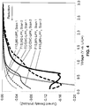
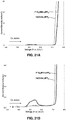
- FIGS. 1A and 1B depict the oxidation stability of F1S 3 MN with LiPF 6 , LiBF 4 , or LiTFSI in current density (mA/cm 2 ) versus voltage (V vs. Li/Li + ).
- the oxidation stability was tested at room temperature with a working electrode as Pt, a counter electrode as Li, a reference electrode as Li/Li + , and a sweep rate of 10 mV/s.
- FIG. 1B depicts a close-up of the same data shown in FIG. 1A .
- the F1S 3 MN-L1PF 6 electrolyte exhibited the best oxidation stability, having a current density of 1 mA/cm 2 at 7.3 V compared to a current density of 1 mA/cm 2 at 6.8 V and 6.2 V for F1S 3 MN-LiBF 4 and F1S 3 MN-LiTFSI, respectively.
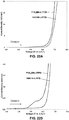
- FIGS. 2A and 2B depict the reduction stability of F1S 3 MN with LiPF 6 , LiBF 4 , or LiTFSI in current density (mA/cm 2 ) versus voltage (V vs. Li/Li + ).
- the reduction stability was tested at room temperature with a working electrode as Pt, a counter electrode as Li, a reference electrode as Li/Li + , and a sweep rate of 10 mV/s.
- FIGS. 2A and 2B are two separate scans.
- the F1S 3 MN-LiPF 6 electrolyte exhibited the best reduction stability.
- FIGS. 3A and 3B depict the oxidation stability of F1S 3 MN or F1S 3 M2 with 1M LiPF 6 in current density (mA/cm 2 ) versus voltage (V vs. Li/Li + ).
- the oxidation stability was tested at room temperature with a working electrode as Pt, a counter electrode as Li, a reference electrode as Li/Li + , and a sweep rate of 10 mV/s.
- FIG. 3B depicts a close-up of the same data shown in FIG. 3A .
- F1S 3 MN demonstrated improved oxidation stability with respect to F1S 3 M2.
- FIG. 4 depicts the reduction stability of F1S 3 MN or F1S 3 M2 with 1M LiPF 6 compared to a carbonate control electrolyte with LiPF 6 in current density (mA/cm 2 ) versus voltage (V vs. Li/Li + ) in two separate scans.
- the reduction stability was tested at room temperature with a working electrode as Pt, a counter electrode as Li, a reference electrode as Li/Li + , and a sweep rate of 10 mV/s.
- F1S 3 MN demonstrated less resistance to reduction compared to F1S 3 M2.
- the thermal stability of both the neat organosilicon solvents and the electrolyte compositions were determined as follows: Approximately 0.75 mL of liquid sample was heated in a sealed cell under an argon purge. The Argon purge was carried to an atmospheric sampling mass spectrometer where any gas phase impurities and/or decomposition products can be detected at very low levels using electron impact mass spectrometry (EI-MS). The sample was held for 1 hour at pre-determined temperature levels that are relevant for battery applications (30, 55, 70, 100, 125, 150, 175, and 200°C). The gas phase decomposition products were identified by comparing fragmentation patterns obtained from the EI-MS to NIST standards.
- EI-MS electron impact mass spectrometry
- the remaining liquid sample was analyzed via NMR spectroscopy for a quantitative analysis of the extent of decomposition. Multiple nuclei were examined to fully analyze all components of the system, including the organosilicon solvent, any carbonate co-solvents, all additives, and the lithium salt (if present).
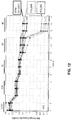
- FIGS. 5A and 5B depict the thermal stability of F1S 3 MN with LiPF 6 .
- F1S 3 MN-LiPF 6 electrolyte (batch ZP815-01) was exposed to temperatures ranging from 30°C to 175°C and analyzed by electron impact mass spectrometry (EI-MS) and nuclear magnetic resonance spectroscopy (NMR) for gas and liquid decomposition products, respectively.. The temperatures at which salient peaks appeared are annotated.
- F1S 3 MN showed no significant gas and/or liquid phase decomposition up to 175°C.
- Me 2 SiF 2 appeared at temperatures of 100-125°C at 81 m/z
- MeSiF 3 appeared at temperatures of 150-175°C at 85 m/z.
- FIG. 5A depicts a close-up of the same data shown in FIG. 5B .
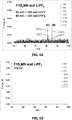
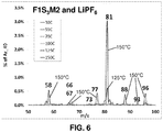
- FIG. 6 depicts the thermal stability of F1S 3 M2 with LiPF 6 .
- F1S 3 M2-LiPF 6 electrolyte was exposed to temperatures ranging from 30°C to 150°C and analyzed by mass spectrometry for decomposition products. The temperatures at which salient peaks appeared are annotated.
- F1S 3 M2 showed decomposition at temperatures ⁇ 125°C.
- Decomposition products included Me 2 SiF 2 and 1,4-dioxane.
- 1 H NMR analysis showed approximately 6% decomposition at 150°C.
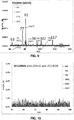
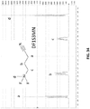
- FIG. 7 depicts the thermal stability of F1S 3 MN with LiTFSI.
- F1S 3 MN-LiTFSI electrolyte was exposed to temperatures ranging from 30°C to 185°C and analyzed by mass spectrometry for decomposition products. The temperatures at which salient peaks appeared are annotated. Gas phase peaks were observed at temperatures ⁇ 150°C. Peaks at 117 and 102 matched patterns observed for F1S 3 MN-LiBF 4 electrolyte and neat solvent (see FIGS. 8 and 9 ).
- FIG. 8 depicts the thermal stability of F1S 3 MN with LiBF 4 .
- F1S 3 MN-LiBF 4 electrolyte was exposed to temperatures ranging from 30°C to 200°C and analyzed by mass spectrometry for decomposition products. The temperatures at which salient peaks appeared are annotated. Gas phase peaks were observed at temperatures ⁇ 175°C. Peaks at 117 and 102 matched patterns observed for neat solvent and F1S 3 MN-LiTFSI electrolyte (see FIGS. 7 and 9 ). 1 H NMR analysis showed no fluorinated decomposition products and ⁇ 0.5% of a non-fluorinated hydrolysis product.
- FIG. 9 depicts the thermal stability of neat F1S 3 MN.
- F1S 3 MN electrolyte was exposed to temperatures ranging from 30°C to 195°C and analyzed by mass spectrometry for decomposition products. The temperatures at which salient peaks appeared are annotated. Gas phase peaks were observed at temperatures ⁇ 150°C. At 150°C, Me 2 SiF 2 was observed (96/81 m/z), but other peaks were not associated with this product. 1 H NMR analysis showed no fluorinated decomposition products and ⁇ 0.5% hydrolysis.
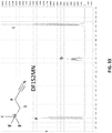
- FIG. 10 depicts the thermal stability of DF1S 3 MN with LiPF 6 .
- DF1S 3 MN-LiPF 6 electrolyte ZP990-01
- EI-MS electron impact mass spectrometry
- NMR nuclear magnetic resonance spectroscopy
- FIG. 11 depicts the thermal stability of F1S 3 MN with LiPF 6 and various carbonate co-solvents and is compared to a carbonate control electrolyte with LiPF 6 .
- Cells containing each electrolyte were charged to 4.25V and then disassembled.
- the lithium nickel cobalt aluminum oxide (NCA) cathode was rinsed with diethylene carbonate and allowed to dry.
- Each sample containing 5 mg of active material and 2 mg of fresh electrolyte was hermetically sealed into a stainless steel DSC pan. DSC scans at a rate of 2 °C/min showed that the carbonate control electrolyte reacted at a much lower onset temperature than any of the organosilicon electrolyte blends.
- the electrolyte where organosilicon is substituted for EMC has a much lower peak heat output than the control electrolyte.
- Blending of electrolytes is completed inside a moisture-free ( ⁇ 5ppm) and oxygen-free ( ⁇ 20ppm) argon glove box. All electrolyte components, including solvents, salts, and additives have been properly dried before blending and are stored in the glove box. Solvent moisture is monitored periodically by Karl Fischer measurement to ensure moisture levels are maintained at ⁇ 20ppm. Generally, solvents are weighed first into a separate vial and mixed until homogeneous. 70% of the solvent is added to a volumetric flask. Lithium (or other) salt is added slowly and stirred by magnetic stir bar until completed dissolved. Any other additives (i.e. VC, LiBOB) are then added slowly and stirred until the solution is homogeneous.
- solvents i.e. VC, LiBOB
- the stir bar is removed and a portion of the remaining solvent is added to complete the volumetric requirement.
- the stir bar is placed back into the volumetric flask and the electrolyte is stirred until homogeneous. After blending is complete the electrolyte is dispensed into a dried vial or alternate container for storage.
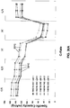
- FIG. 12 depicts the discharge capacity at 30°C of cells containing various electrolyte solvents.
- Three different electrolyte solvents were tested in Lithium Ion cells over a series of cycles at different C-rates in a 2032-size coin cell assembly (assembly stack as in FIG. 13 ) containing a graphite anode, a lithium nickel cobalt aluminum oxide (NCA) cathode, and "2500"-type separator from Celgard, LLC (Charlotte, NC).
- NCA lithium nickel cobalt aluminum oxide
- the three electrolyte solvents were: (1) control EPA6 carbonate electrolyte comprising 1:1 by volume ethylene carbonate (EC) and diethyl carbonate (DEC) (triangles); (2) an F1S 3 MN-based electrolyte comprising 79% F1S 3 MN, 20% EC, 1 M LiPF 6 , and solid electrolyte interphase (SEI)-forming additives (squares); and (3) an F1S 3 M2-based electrolyte, comprising 79% F1S 3 M2, 20% EC, 1 M LiPF 6 , and SEI-forming additives (circles). As shown in FIG. 12 , the F1S 3 MN-based electrolyte is equivalent to EPA6 at the 4C rate.
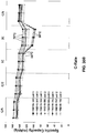
- FIG. 14 depicts the discharge capacity at 55°C of cells containing the same electrolytes as shown in, and described for FIG. 12 .
- the cells were assembled in the same manner and cycled at a C/2 rate.
- the F1S 3 MN-based solvent had improved cycling stability at 55°C compared to both the carbonate control and the F1S 3 M2-based electrolyte.
- EDLC Symmetric electrical double layer capacitors
- Acetonitrile (AN, Sigma Aldrich, anhydrous, 99.8%) was used as a co-solvent.
- Zorflex FM10 100% activated carbon (AC) cloth from Calgon carbon was used for both electrodes.
- FM10 has 1000-2000 m2/g surface area, 0.5 mm thickness, and 120 g/m2 area density. The AC cloth was punched to 15 mm diameter discs, and used directly as electrodes without any binder or conductive additives.
- FIG. 16 shows the cyclic voltammograms of EDLC cells with OS electrolytes containing TEA-BF 4 salt.
- Electrolyte ZX1193 included 1.0M TEA-BF 4 dissolved in 70 volume percent DF1S 2 MN and 30 volume percent acetonitrile. Electrolyte ZX1190 included 0.8M TEA-BF 4 dissolved into blended DF1S 2 MN and acetonitrile solvents, 60:40 by volume.
- the EDLC cells with both electrolyte formulations showed the regular and symmetric features to the 0 horizontal axis, indicating a non-redox or faradic properties of the cell.
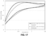
- FIG. 17 shows the cyclic voltammograms of EDLC cells with ZX1170 electrolyte and ZX1184 electrolyte containing TBP-PF 6 salt.
- Electrolyte ZX1170 has 1.2M TBP-PF 6 dissolved into F1S 3 MN
- electrolyte ZX1184 has 1.2M TBP-PF 6 dissolved into DF1S 2 MN.
- the non-redox or faradic properties can also be observed from the EDLC cells with both electrolyte ZX1170 and ZX1184 formulations.
- Scheme 6 depicts a synthesis scheme for 1ND1N.
- 1ND1N cannot be chemically dried with sodium (Na), calcium oxide (CaO), or calcium hydride (CaH 2 ).
- 1ND1N has great oxidation stability but lower reduction resistance than 1ND1.
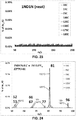
- FIG. 18 depicts the oxidation stability of 1ND1N with 1M LiPF 6 or 1M LiTFSI in current density (mA/cm 2 ) versus voltage (V vs. Li/Li + ).
- the oxidation stability was tested at room temperature with a working electrode as Pt, a counter electrode as Li, a reference electrode as Li/Li + , and a sweep rate of 10 mV/s.
- FIG. 19 depicts the reduction stability of 1ND1N with 1M LiPF 6 or 1M LiTFSI in current density (mA/cm 2 ) versus voltage (V vs. Li/Li + ).
- the reduction stability was tested at room temperature with a working electrode as Pt, a counter electrode as Li, a reference electrode as Li/Li + , and a sweep rate of 10 mV/s. Two separate scans for each electrolyte are shown.
- FIGS. 20A and 20B depict current density (mA/cm 2 ) versus voltage (V vs. Li/Li + ) for cycling scans with 1ND1N and 1M LiPF 6 or 1M LiTFSI from 0 to 6 V and from 6 to 0 V.
- FIG. 20A depicts a first cycle.
- FIG. 20B depicts a second cycle.
- FIGS. 21A and 21B depict the oxidation stability of F1S 3 MN or 1ND1N with 1M LiPF 6 in current density (mA/cm 2 ) versus voltage (V vs. Li/Li + ).
- the oxidation stability was tested at room temperature with a working electrode as Pt, a counter electrode as Li, a reference electrode as Li/Li + , and a sweep rate of 10 mV/s.
- FIG. 21B depicts a close-up of the same data shown in FIG. 21A .
- the F1S 3 MN-LiPF 6 electrolyte had a current density of 1 mA/cm 2 at 7.3 V, and the 1ND1N-LiPF 6 electrolyte had a current density of 1 mA/cm 2 at 7.2 V.
- FIGS. 22A and 22B depict the oxidation stability of F1S 3 MN or 1ND1N with 1M LiTFSI in current density (mA/cm 2 ) versus voltage (V vs. Li/Li + ).
- the oxidation stability was tested at room temperature with a working electrode as Pt, a counter electrode as Li, a reference electrode as Li/Li + , and a sweep rate of 10 mV/s.
- FIG. 22B depicts a close-up of the same data shown in FIG. 22A .
- the F1S 3 MN-LiTFSI electrolyte had a current density of 1 mA/cm 2 at 6.2 V, and the 1ND1N-LiTFSI electrolyte had a current density of 1 mA/cm 2 at 6.5 V.
- FIG. 23 depicts the thermal stability of neat 1ND1N.
- 1ND1N was exposed to temperatures ranging from 30°C to 189°C and analyzed by mass spectrometry for decomposition products.
- 1ND1N showed no liquid or gas phase decomposition products up to 189°C.
- 1 H NMR showed ⁇ %5 decomposition.
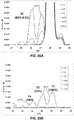
- FIG. 24 depicts the thermal stability of 1ND1N with LiPF 6 .
- 1ND1N-LiPF 6 electrolyte was exposed to temperatures ranging from 30°C to 150°C and analyzed by mass spectrometry for decomposition products. The temperatures at which salient peaks appeared are annotated.
- 1ND1N showed gas phase decomposition ⁇ 70°C, but no vigorous reaction was observed up to 150°C.
- FIG. 25A depicts a close-up of the mass spectrum profile as described with respect to FIG. 24 from 24-30 m/z.
- FIG. 25B depicts a close-up of the mass spectrum profile as described with respect to FIG. 24 from 49-55 m/z.
- the temperatures at which salient peaks in FIGS. 25A and 25B appeared are annotated.
- FIG. 25B indicate that acrylonitrile is likely present.
- the presence of HCN cannot be definitively confirmed or disconfirmed due to the presence of peaks at 26 and 27 m/z in the NIST spectra.
- the spectrum in FIG. 25A shows a greater peak intensity at 26 m/z compared to 27 m/z, which supports the presence of acrylonitrile.
- the magnitude of the peak at 27 m/z is greater than expected for acrylonitrile alone.
- FIG. 26 depicts the thermal stability of 1ND1N with LiTFSI, vinylene carbonate (VC) and lithium bis(oxalato)borate (LiBOB).
- 1ND1N-LiTFSI-VC-LiBOB was exposed to temperatures ranging from 30°C to 185°C and analyzed by mass spectrometry for decomposition products.
- 1ND1N-LiTFSI-VC-LiBOB showed no gas phase decomposition products up to 185°C.
- 1 H NMR showed an increase in hydrolysis from 3% (in the unheated sample) to 18.7% (after heating), which was likely due to a delay before the NMR analysis was performed.
- FIG. 27 depicts the thermal stability of 1ND1N with LiBF 4 .
- 1ND1N-LiBF 4 was exposed to temperatures ranging from 30°C to 125°C and analyzed by mass spectrometry for decomposition products. The temperatures at which salient peaks appeared are annotated. Gas phase products evolved at ⁇ 30°C. As expected, Me 2 SiF 2 (81 m/z) (96 g/mol) was observed. No acrylonitrile was observed. 1 H NMR showed 3.7% hydrolysis and 34.2% fluorinated products (3 sets of peaks). 19 F NMR showed that all F in the system was bonded to Si. No BF 4 remained. There was insufficient F to fully decompose 1ND1N ( ⁇ 5M 1ND1N versus 4 M F).
- FIG. 28 depicts the discharge capacity of cells containing various electrolytes at a variety of C-rates.
- the electrolyte solvents were: (1) 1ND1N; (2) 1ND1N with 20% ethylene carbonate (EC) co-solvent (1ND1N_EC); and (3) 1ND2 with 20% EC co-solvent (1ND2_EC). All formulations also contained SEI-forming additives and 1 M LiPF 6 salt. As shown in FIG. 28 , 20% EC co-solvent improved the performance of 1ND1N. With 20% EC co-solvent, 1ND1N showed diminished performance compared to 1ND2 at all C-rates.
- EC ethylene carbonate
- FIG. 29 depicts the discharge capacity of cells containing various other electrolyte solvents.
- the electrolyte solvents were: (1) 1ND1N with 20% EC co-solvent, 1 M LiPF 6 and SEI-forming additives (1ND1N-EC- LiPF 6 , shown as 1ND1N_EC in FIG. 29 ); (2) 1ND1N with 20% EC co-solvent, 1 M LiTFSI and SEI-forming additives (1ND1N-EC-LiTFSI, shown as 1ND1N_T in FIG. 29 ); and ( 3 ) 1ND2 with 20% EC co-solvent, 1 M LiPF 6 and SEI-forming additives (1ND2-EC-LiPF 6 , shown as CP597-07 in FIG. 29 ).
- the 1ND1N-EC-LiPF 6 combination and the 1ND1N-EC-LiTFSI combination showed performance comparable to the 1ND2-EC-LiPF 6 combination.
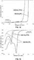
- FIGS. 30A and 30B depict the discharge capacity of cells containing a 1ND1N-LiPF 6 -based electrolyte or a 1ND1N-LiTFSI-based electrolyte, respectively, at a variety of C-rates.
- the cells were charged with a constant-current/constant-voltage (CCCV) procedure at C/5, C/2, 1C or 2C rates to 4.1 V.
- CCCV constant-current/constant-voltage
- the cells were discharged each cycle to 3.0 V with a constant current at the same rate that they were charged.
- the 1ND1N-LiPF 6 -based electrolyte solution included 1 M LiPF 6 and 1ND1N (batch ZP780-01), and the charging/discharging was performed at 30°C or 55°C.
- the 1ND1N-LiTFSI-based electrolyte solution included 1 M LiTFSI and 1ND1N, batch (ZT781-01), and the charging/discharging was performed at 30°C, 55°C, or 70°C.
- the 1ND1N-LiTFSI-based electrolyte displayed better rate capability than the 1ND1N-LiPF 6 -based electrolyte.
- Table 1 shows physical properties of selected organosilicon (OS) compounds (1S 3 MN, F1S 3 MN, F1S 3 cMN, DF1S 3 MN, DF1S 2 MN, and F1S 3 M2) as neat solvents and formulated electrolyte solutions.
- Table 2 shows physical properties of neat 1ND1N, 1ND1, 1ND2, and F1S 3 MN and various electrolyte compositions containing them.
- the conductivity has units of mS/cm
- the viscosity has units of cP
- the flash point is in degrees Celsius.
- F1S 3 MN and 1ND1N are both suitable for use as electrolyte solvents in Li-ion batteries.
- F1S 3 MN and DF1S 2 MN have demonstrated function as electrolyte solvents in EDLC devices.
- F1S 3 MN shows very high thermal stability (measured by 1 H NMR) with all salts tested. F1S 3 MN shows the highest thermal stability of any OS with LiPF 6 (175°C), with no observed decomposition. F1S 3 MN does produce gas phase products as neat solvent, with LiBF 4 , and with LiTFSI. These gas phase products can be attributed to low levels of F1S 3 MN evaporation. F1S 3 MN shows increased voltage stability (higher oxidation potential with wide window) compared to F1S 3 M2. F1S 3 MN provides equivalent performance as EPA6 up to a rate of 4C.
- LiBOB has limited solubility in F1S 3 MN ( ⁇ 0.03M) without co-solvent, but LiBOB solubility improves (>0.1M) with use of co-solvent (i.e. 20% EC).
- the decomposition products of F1S 3 MN are Me 2 SiF 2 and MeSiF 3 , both of which are gases.
- 1ND1N shows no gas phase decomposition as a neat solvent or in combination with LiTFSI electrolyte up to 185-190°C.
- the combination of 1ND1N with LiTFSI electrolyte shows promise up to 70°C and higher.
- 1ND1N with LiPF 6 is more thermally stable than either 1ND1 or 1ND2 with LiPF 6 . It forms acrylonitrile above 125°C.
- 1ND1N reacts at room temperature with LiBF 4 . However, there is insufficient F to fully decompose the 1ND1N, and it does not form acrylonitrile.
- the rate performance of 1ND1N is slightly lower than 1ND2.
Landscapes
- Chemical & Material Sciences (AREA)
- Engineering & Computer Science (AREA)
- Chemical Kinetics & Catalysis (AREA)
- Electrochemistry (AREA)
- Power Engineering (AREA)
- Organic Chemistry (AREA)
- Microelectronics & Electronic Packaging (AREA)
- General Chemical & Material Sciences (AREA)
- Manufacturing & Machinery (AREA)
- Inorganic Chemistry (AREA)
- Materials Engineering (AREA)
- Physics & Mathematics (AREA)
- Condensed Matter Physics & Semiconductors (AREA)
- General Physics & Mathematics (AREA)
- Secondary Cells (AREA)
- Electric Double-Layer Capacitors Or The Like (AREA)
- Primary Cells (AREA)
Description
- Liquid electrolytes in Li-ion batteries conventionally comprise a lithium salt, usually LiPF6, in an organic solvent blend of ethylene carbonate (EC) and one or more co-solvents such as dimethyl carbonate (DMC), diethyl carbonate (DEC), or ethylmethyl carbonate (EMC). Unfortunately, LiPF6 is unstable in these carbonate solvents above 60 °C, as well as at charge voltages above 4.3 volts. Operation of a Li-ion battery above these temperatures or voltages results in rapid degradation of electrode materials and battery performance. In addition, current Li-ion electrolyte solvents exhibit flashpoints around 35°C, and are the major source of the energy released during an extreme Li-ion cell failure. Given these significant limitations, current electrolytes are impeding the development of advanced Li-ion batteries for all uses, including portable products, electric drive vehicles (EDVs), and utility scale use. A dramatic reduction in battery failure rate is also required for large scale Li-ion batteries to effectively serve applications in EDVs and grid storage.
- Thus, there is a long-felt and unmet need for improved electrolyte solutions in energy storage devices such as Li-ion batteries.
- Disclosed herein are organosilicon (OS) compounds for use as electrolyte solvents in electrochemical devices, among other uses.
- In general, OS compounds are environmentally friendly, non-flammable, high temperature-resistant materials. These characteristics make OS materials well-suited for use as electrolyte solvents, binders, and coatings in energy storage devices. OS-based electrolytes are compatible with all lithium (Li) based electrochemical systems, including primary and rechargeable batteries, (i.e. Li-ion, Li-air), and capacitors (i.e. super/ultra-capacitors). The process of designing OS-based electrolytes into a Li battery involves limited changes in the cell design, and these electrolytes can be incorporated into production operations with existing manufacturing processes and equipment.
- The OS compounds described herein can be used as liquid electrolyte solvents that replace the carbonate based solvent system in traditional Li-ion batteries. The OS-based solvents provide significant improvements in performance and abuse tolerance in Li-ion batteries, including increased thermal stability for longer life at elevated temperatures, increased electrolyte flash points for improved safety, increased voltage stability to allow use of high voltage cathode materials and achieve higher energy density, reduced battery failure rates for consistency with the requirements for large scale Li batteries used in EDV and grid storage applications, and compatibility with materials currently in use in Li-ion batteries for ease of adoption in current designs. Electrical double-layer capacitor (EDLC) devices have also demonstrated functionality with OS based electrolytes. The OS compounds described herein can be used in OS-based electrolyte blends to meet the requirements of specific applications in the industrial, military, and consumer product devices.
-
US 3,053,874 (Union Carbide Corporation) discloses a process which uses cyanoalkylfluorosilanes as starting materials for the preparation of carboxyalkylsiloxanes. There is no disclosure of the use of those compounds in an electrolytic composition or an electrochemical device. -
JP 2000243440 (A - Cyanopropyl chloroalkylsilane compounds are disclosed in the PubChem compound database of 27 March 2005 (XP 002763115) at accession no. 14479.
- The objects and advantages of the compounds and electrolyte formulations will appear more fully from the following detailed description and accompanying drawings.
- In accordance with a first aspect of the present invention, there is disclosed an electrolytic composition comprising a compound of Formula III as defined in
claim 1. In accordance with a second aspect of the present invention, there is disclosed an electrochemical device as claimed inclaim 6. - In all versions of the compounds, "halogen," includes fluoro, chloro, bromo, and iodo. Fluoro and chloro are the preferred halogen substituents. The term "lithium-containing salt" explicitly includes, but is not limited to, LiClO4, LiBF4, LiAsF6, LiPF6, LiCF3SO3, Li(CF3SO2)2N, Li(CF3SO2)3C, LiN(SO2C2F5)2, lithium alkyl fluorophosphates and lithium bis(chelato)borates.
- The compounds disclosed herein are highly useful for formulating electrolytes for use in charge-storage devices of all kinds (e.g., cells, batteries, capacitors, and the like).
-
-
FIG. 1A depict the oxidation stability of F1S3MN with LiPF6, LiBF4, or LiTFSI in current density (mA/cm2) versus voltage (V vs. Li/Li+).FIG. 1B depicts a close-up of the same data shown inFIG. 1A . -
FIG. 2A and FIG. 2B depict duplicate runs to measure the reduction stability of F1S3MN with LiPF6, LiBF4, or LiTFSI in current density (mA/cm2) versus voltage (V vs. Li/Li+). -
FIG. 3A depicts the oxidation stability of F1S3MN or F1S3M2 with 1M LiPF6 in current density (mA/cm2) versus voltage (V vs. Li/Li+).FIG. 3B depicts a close-up of the same data shown inFIG. 3A . -
FIG. 4 depicts the reduction stability of F1S3MN or F1S3M2 with 1M LiPF6 in current density (mA/cm2) versus voltage (V vs. Li/Li+). -
FIGS. 5A and 5B depict the thermal stability of F1S3MN with LiPF6.FIG. 5A depicts a close-up of the same data shown inFIG. 5B . -
FIG. 6 depicts the thermal stability of F1S3M2 with LiPF6. -
FIG. 7 depicts the thermal stability of F1S3MN with LiTFSI. -
FIG. 8 depicts the thermal stability of F1S3MN with LiBF4. -
FIG. 9 depicts the thermal stability of neat F1S3MN. -
FIG. 10 depicts the thermal stability of DF1S3MN with 20% EC and VC/LiBOB. -
FIG. 11 depicts the enhanced stability of F1S3MN electrolytes compared to carbonate control electrolyte heated with de-lithiated NCA cathode. -
FIG. 12 depicts the discharge capacity of cells containing various electrolyte solvents at a variety of C-rates at 30°C. -
FIG. 13 depicts the construction of a test cell. -
FIG. 14 depicts the discharge capacity of cells containing the same electrolyte solvents shown inFIG. 12 at a variety of C-rates at 55°C. -
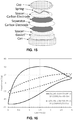
FIG. 15 depicts the construction of an EDLC device. -
FIG. 16 depicts the performance of an EDLC device containing DF1S2MN electrolyte with TEA-BF4. -
FIG. 17 depicts the performance of an EDLC device containing various electrolyte solvents with TBP-PF6. -
FIG. 18 depicts the oxidation stability of 1ND1N with 1M LiPF6 or 1M LiTFSI in current density (mA/cm2) versus voltage (V vs. Li/Li+). -
FIG. 19 depicts the reduction stability of 1ND1N with 1M LiPF6 or 1M LiTFSI in current density (mA/cm2) versus voltage (V vs. Li/Li+). -
FIGS. 20A and 20B depict current density (mA/cm2) versus voltage (V vs. Li/Li+) for cycling scans with 1ND1N and 1M LiPF6 or 1M LiTFSI from 0 to 6 V and from 6 to 0 V.FIG. 20A depicts a first cycle.FIG. 20B depicts a second cycle. -
FIG. 21A depicts the oxidation stability of F1S3MN or 1ND1N with 1M LiPF6 in current density (mA/cm2) versus voltage (V vs. Li/Li+).FIG. 21B depicts a close-up of the same data shown inFIG. 21A . -
FIG. 22A depicts the oxidation stability of F1S3MN or 1ND1N with 1M LiTFSI in current density (mA/cm2) versus voltage (V vs. Li/Li+).FIG. 22B depicts a close-up of the same data shown inFIG. 22A . -
FIG. 23 is a mass spectrum illustrating the thermal stability of neat 1ND1N. -
FIG. 24 is a mass spectrum illustrating the thermal stability of 1ND1N with LiPF6. -
FIG. 25A depicts a close-up of the mass spectrum profile as described with respect toFIG. 24 from 24-30 m/z.FIG. 25B depicts a close-up of the mass spectrum profile as described with respect toFIG. 24 from 49-55 m/z. -
FIG. 26 depicts the thermal stability of 1ND1N with LiTFSI, vinylene carbonate (VC) and lithium bis(oxalato)borate (LiBOB). -
FIG. 27 depicts the thermal stability of 1ND1N with LiBF4. -
FIG. 28 depicts the discharge capacity of cells containing various electrolytes at a variety of C-rates. -
FIG. 29 depicts the discharge capacity of cells containing various other electrolyte solvents comparing the first cycle to the 50th cycle. -
FIG. 30A depicts the discharge capacity of cells containing a 1ND1N-LiPF6-based electrolyte at a variety of C-rates.FIG. 30B depicts the discharge capacity of cells containing a 1ND1N-LiTFSI-based electrolyte at a variety of C-rates. -
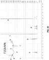
FIG. 31 is the 1H-NMR spectrum (in CDCl3) of 1ND1N with peak assignments. -
FIG. 32 is the 1H-NMR spectrum (in CDCl3) of F1S3MN with peak assignments. -
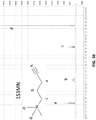
FIG. 33 is the 1H-NMR spectrum (in CDCl3) of DF1S2MN with peak assignments. -
FIG. 34 is the 1H-NMR spectrum (in CDCl3) of DF1S3MN with peak assignments. -
FIG. 35 is the 1H-NMR spectrum (in CDCl3) of F1S3cMN with peak assignments. -
FIG. 36 is the 1H-NMR spectrum (in CDCl3) of 1S3MN with peak assignments. - Throughout the description, a number of shorthand abbreviations will be used to designate various organosilicon compounds more easily. The following conventions are used:
- The nNDnN compounds (not in accordance with the invention) have the general formula:

- The FnSnMN compounds have the general formula:

- wherein R1 , R2, and R3 are the same or different and are independently selected from the group consisting of C1 to C6 linear or branched alkyl and fluorine, and wherein at least one of R1, R2, or R3 is fluorine;
- "Spacer" is selected from the group consisting of C3 to C6 linear or branched alkylene, alkenylene, or alkynylene; and
- R4 is cyano Related compounds disclosed herein (not in accordance with the invention) have the structures:


- The compounds disclosed herein can be made by a number of different routes. A general approach that can be used to fabricate the compounds is as follows:

- The various R groups are as defined herein; "n" is a positive integer.
- The compounds disclosed herein can also be fabricated via the following approach:

- The compounds disclosed herein are also made by a number of specific routes, including the following reaction schemes:


- LiTFSI is a commercial product supplied by several international suppliers:

- The elements and method steps described herein can be used in any combination whether explicitly described or not.
- All combinations of method steps as used herein can be performed in any order, unless otherwise specified or clearly implied to the contrary by the context in which the referenced combination is made.
- As used herein, the singular forms "a," "an," and "the" include plural referents unless the content clearly dictates otherwise.
- Numerical ranges as used herein are intended to include every number and subset of numbers contained within that range, whether specifically disclosed or not. Further, these numerical ranges should be construed as providing support for a claim directed to any number or subset of numbers in that range. For example, a disclosure of from 1 to 10 should be construed as supporting a range of from 2 to 8, from 3 to 7, from 5 to 6, from 1 to 9, from 3.6 to 4.6, from 3.5 to 9.9, and so forth.
- It is understood that the compounds and compositions disclosed herein are not confined to the particular construction and arrangement of parts herein illustrated and described, but embraces such modified forms thereof as come within the scope of the claims.
- The presently disclosed compounds are organosilicon compounds having a shared structural feature in the form of a one or more terminal substituents that comprise a carbon-nitrogen double or triple bond, such as a cyano (R-C≡N), cyanate (R-O-C≡N), isocyanate (R-N=C=O), thiocyanate (R-S-C≡N), and/or isothiocyanate (R-N=C=S). Included among the preferred compounds are the following structures:


1S3MN 4-(trimethylsilyl)butanenitrile 3-cyano propyltrimethylsilane F1S3MN 4-(fluorodimethylsilyl)butanenitrile 3-cyanopropyldimethylfluorosilane 

DF1S3MN 4-(difluoromethylsilyl)butanenitrile 3-cyanopropylmethyldifluorosilane TF1S3MN 4-(trifluorosilyl)butanenitrile 3-cyanopropyltrifluoro silane 

iso1S3MN 3-(trimethylsilyl)butanenitrile iso F1S3MN 3-(fluorodimethylsilyl)butanenitrile 

isoDF1S3MN 3-(difluoromethylsilyl)butanenitrile isoTF1 S3MN 3-(trifluorosilyl)butanenitrile 

1S2MN 3-(trimethylsilyl)propanenitrile 2-cyanoethyltrimethylsilane F1S2MN 3-(fluorodimethylsilyl)propanenitrile 2-cyanoethyldimethylfluorosilane 

DF1S2MN 3-(difluoromethylsilyl)propanenitrile 2-cyanoethylmethyldifluorosilane TF1S2MN 3-(trifluorosilyl)propanenitrile 2-cyanoethyltrifluoro silane - The above structures are all depicted with a terminal cyano group. This is for purposes of brevity only. The analogous compounds having a terminal cyanate, isocyanate, or thiocyanate moiety in place of the cyano moiety are explicitly within the scope of the disclosure. Likewise, the halogenated compounds are depicted above as fluorinated compounds. The analogous compounds having other halogen substituents (chlorine, bromine, and/or iodine) in place of fluorine atoms are explicitly within the scope of the present disclosure. For each compound listed, two alternative systematic names are provided (the first of each pair of names designates the fundamental core as a nitrile; the second designated the fundamental cores as silane.) Additionally, each compound has been given a short-hand designation in which DF = difluoro, TF = trifluoro, and "Sn" designates the alkylene spacer between the silicon atom and the terminal cyanate, isocyanate, or thiocyanate moiety and "n" represents the number of carbon atoms in the spacer. The physical properties of selected organosilicon (OS) compounds are presented in Table 1.
- As shown in Table 1, Reduced viscosity, higher conductivity, and lower flash point with added fluorine and reduced spacer length. DF1S2MN has lowest viscosity and highest conductivity.
Table 1. Physical Properties (with 20% EC, additives, 1M LiPF6) Solvent Properties of Neat Solvent Properties of Electrolytes with 1M LiPF6 MW (g/mol) Flash Point (°C) Di-electric Constant (neat) B.P. (°C) Co-solvent 30 °C Conductivity (mS/cm) 30 °C Viscosity (cP) Flash Point (°C) 1S3MN 141 72 12.6 200 Not compatible with EC F1S3MN 145 82 16.8 249 20% EC 3.5 9.1 82 F1S3cMN 159 80 16.6 n/a 20% EC 2.6 10.6 n/a DF1S3MN 149 78 18.2 202 20% EC 4.8 8.2 78 DF1S2MN 135 64 19.5 182 20% EC 5.8 6.9 64 F1S3M2 238 112 7.2 233 20% EC 3.0 14.0 112 


- The physical properties of neat 1ND2, 1ND1, 1ND1N and F1S3MN, as well as electrolyte solutions containing these solvents, are shown in Table 2:
Table 2: Physical Properties of Solvents and Electrolytes Solvent Properties of Neat Solvent Properties of Electrolytes with 1M Salt RT Visc. (cP) Flash Point (°C) Di-electric Constant (neat) B.P. (°C) Batch, Co-solvent, Salt 30 °C Conductivity (mS/cm) 30 °C Viscosity (cP) Flash Point (°C) 1ND1N 8.3 168 30 n/a ZP791 20% EC LiPF61.9 33 80 ZP779 ZP780 LiPF6 1.3 29 72 ZT778 LiTFSI 1.1 37 166 1ND1 n/a 85 8.1 n/a CP630 20% EC LiPF64.5 5.1 52 1ND2 3.5 138 6.4 288 CP597 20% EC LiPF63.9 12.5 130 F1S3MN 2.0 82 16.8 249 ZP826 20% EC LiPF63.5 9.1 82 ZP825 LiPF6 2.7 8.3 58 - In addition to the organosilicon compounds disclosed herein, the present electrolyte compositions may include conventional non-silicon co-solvents. For example, the present electrolyte compositions may include nitriles and carbonates, such as acetonitrile, ethylene carbonate (EC), dimethyl carbonate (DMC), diethyl carbonate (DEC), or ethylmethyl carbonate (EMC). The instant electrolyte compositions may include non-silicon co-solvents at a wide range of concentrations, including but not limited to, about 1 wt% to about 40 wt%. Examples of suitable co-solvent concentrations include about 1 wt%, about 5 wt%, about 10 wt%, about 15 wt%, about 20 wt%, about 25 wt%, about 30 wt%, about 40 wt% or a range between and including any of the preceding amounts.
-
Scheme 1 depicts a synthesis scheme for F1S3MN. [F] indicates a fluorinating agent, such as HF, NH4FHF, or other fluorinating agent. NH4FHF is preferably used as a fluorinating agent for laboratory scale synthesis. If HF is used, the only byproduct is HCl. The synthesized F1S3MN compound is washed from the solid salt with hexane, distilled, dried with CaO, and distilled again.
-
Scheme 2 depicts a synthesis scheme for F1S3MN using NH4FHF as a fluorinating agent. Using Karstedt's catalyst (Platinum(0)-1,3-divinyl-1,1,3,3-tetramethyldisiloxane complex solution, Cat. No. 479519, Sigma-Aldrich, St. Louis, MO), about 3% substitution on the secondary carbon occurs, generating isoF1S3MN. The isoF1S3MN has a lower boiling point than F1S3MN, and most of it can be separated by fractional distillation.
-
Scheme 3 depicts an alternative, shorter synthesis scheme for F1S3MN using a Cl1S3MN intermediate. The Cl1S3MN intermediate can be obtained by Gelest, Inc. (Product Code SIC2452.0, 11 East Steel Road, Morrisville, PA). Use of the Cl1S3MN intermediate reduces the time spent during synthesis.
-
Scheme 4 depicts yet another synthesis scheme for F1S3MN. As withScheme 1, [F] indicates a fluorinating agent, such as HF, NH4FHF, or other fluorinating agent. The use of HF as fluorinating agent in this synthesis scheme will not give solid byproducts, so there is no need of hexane extraction and filtration of solid. The only byproduct is HCl.
-
Scheme 5 depicts yet another synthesis scheme for F1S3MN. As withScheme 1, [F] indicates a fluorinating agent, such as HF, NH4FHF, or other fluorinating agent.
- In the preferred route, allyl cyanide is heated to about 100°C with a small amount of Karstedt's catalyst. Dimethylchlorosilane was added dropwise and refluxed 4 hours. After cooling to room temperature, the mixture was fluorinated using 1 mol equivalent of ammonium hydrogen fluoride at room temperature. Cold hexane was added to the mixture, the solid was filtered off, and the solvent evaporated. Calcium oxide was added to the crude product and it was distilled under vacuum between 45-55°C at 0.4 Torr to yield the desired product, F1S3MN.
- Computational chemistry methods were used to calculate electrochemical properties of various organosilicon molecules. We used the GAMESS program developed by the Gordon research group at Iowa State University for the Density Function Theory (DFT) molecular orbital calculations. The HOMO (highest occupied molecular orbital) and LUMO (lowest unoccupied molecular orbital) energy levels, which correlate to the reduction and oxidation potentials of compounds, were calculated at the B3LYP/DZV level.
- The oxidative stability of electrolytes containing organosilicon solvents was determined using linear sweep voltammetry (LSV) or cyclic voltammetry (CV) in a 3-electrode cell. A platinum microelectrode was used as the working electrode with lithium metal as both the counter and reference electrode. The potential of the system was increased from the open circuit voltage (OCV) to 6 or 8V (vs. Li/Li+) at a scan rate of 10 mV/s. The resulting current density (mA/cm2) was recorded at each potential with a higher current indicating an oxidative reaction (i.e., lower oxidative stability). For the linear sweep voltammetry, 8V was used as a final potential to evaluate the fundamental oxidative stability of the material across a wider voltage range. For the cyclic voltammetry, 6V was used to evaluate the material across multiple scans under potentials more relevant to traditional battery applications. Multiple scans were conducted in the cyclic voltammetry experiments to determine the reversibility/irreversibility of any reactions observed.
- The reductive stability of electrolytes containing organosilicon solvents was determined using linear sweep voltammetry (LSV) in a 3-electrode cell. A glassy carbon electrode was used as the working electrode with lithium metal as both the counter and reference electrode. The potential of the system was decreased from the open circuit voltage (OCV, typically 3V) to 0.1V (vs. Li/Li+) at a scan rate of 10 mV/s. The resulting current density (mA/cm2) was recorded at each potential with a greater current indicating a reduction reaction (i.e., lower reductive stability). Two scans were conducted to evaluate if the reductive processes were reversible or irreversible (i.e., passivating).
- Molecular orbital diagrams for F1S3MN and F1S3M2, not shown, reveal that the energy difference between the highest occupied molecular orbital (HOMO) and the lowest unoccupied molecular orbital (LUMO) is greater for F1S3MN (9.07 eV) than for F1S3M2 (8.20 eV). F1S3MN also has a higher oxidation potential (-8.75 eV) than F1S3M2 (-6.84 eV).
-
FIGS. 1A and 1B depict the oxidation stability of F1S3MN with LiPF6, LiBF4, or LiTFSI in current density (mA/cm2) versus voltage (V vs. Li/Li+). The oxidation stability was tested at room temperature with a working electrode as Pt, a counter electrode as Li, a reference electrode as Li/Li+, and a sweep rate of 10 mV/s.FIG. 1B depicts a close-up of the same data shown inFIG. 1A . The F1S3MN-L1PF6 electrolyte exhibited the best oxidation stability, having a current density of 1 mA/cm2 at 7.3 V compared to a current density of 1 mA/cm2 at 6.8 V and 6.2 V for F1S3MN-LiBF4 and F1S3MN-LiTFSI, respectively. -
FIGS. 2A and 2B depict the reduction stability of F1S3MN with LiPF6, LiBF4, or LiTFSI in current density (mA/cm2) versus voltage (V vs. Li/Li+). The reduction stability was tested at room temperature with a working electrode as Pt, a counter electrode as Li, a reference electrode as Li/Li+, and a sweep rate of 10 mV/s.FIGS. 2A and 2B are two separate scans. The F1S3MN-LiPF6 electrolyte exhibited the best reduction stability. -
FIGS. 3A and 3B depict the oxidation stability of F1S3MN or F1S3M2 with 1M LiPF6 in current density (mA/cm2) versus voltage (V vs. Li/Li+). The oxidation stability was tested at room temperature with a working electrode as Pt, a counter electrode as Li, a reference electrode as Li/Li+, and a sweep rate of 10 mV/s.FIG. 3B depicts a close-up of the same data shown inFIG. 3A . F1S3MN demonstrated improved oxidation stability with respect to F1S3M2. -
FIG. 4 depicts the reduction stability of F1S3MN or F1S3M2 with 1M LiPF6 compared to a carbonate control electrolyte with LiPF6 in current density (mA/cm2) versus voltage (V vs. Li/Li+) in two separate scans. The reduction stability was tested at room temperature with a working electrode as Pt, a counter electrode as Li, a reference electrode as Li/Li+, and a sweep rate of 10 mV/s. F1S3MN demonstrated less resistance to reduction compared to F1S3M2. - The thermal stability of both the neat organosilicon solvents and the electrolyte compositions were determined as follows: Approximately 0.75 mL of liquid sample was heated in a sealed cell under an argon purge. The Argon purge was carried to an atmospheric sampling mass spectrometer where any gas phase impurities and/or decomposition products can be detected at very low levels using electron impact mass spectrometry (EI-MS). The sample was held for 1 hour at pre-determined temperature levels that are relevant for battery applications (30, 55, 70, 100, 125, 150, 175, and 200°C). The gas phase decomposition products were identified by comparing fragmentation patterns obtained from the EI-MS to NIST standards. Following the heating experiment (and detection/collection of all gas phase products), the remaining liquid sample was analyzed via NMR spectroscopy for a quantitative analysis of the extent of decomposition. Multiple nuclei were examined to fully analyze all components of the system, including the organosilicon solvent, any carbonate co-solvents, all additives, and the lithium salt (if present).
-
FIGS. 5A and 5B depict the thermal stability of F1S3MN with LiPF6. F1S3MN-LiPF6 electrolyte (batch ZP815-01) was exposed to temperatures ranging from 30°C to 175°C and analyzed by electron impact mass spectrometry (EI-MS) and nuclear magnetic resonance spectroscopy (NMR) for gas and liquid decomposition products, respectively.. The temperatures at which salient peaks appeared are annotated. F1S3MN showed no significant gas and/or liquid phase decomposition up to 175°C. Me2SiF2 appeared at temperatures of 100-125°C at 81 m/z, and MeSiF3 appeared at temperatures of 150-175°C at 85 m/z. However, the 81 m/z and 85 m/z peaks appeared inconsistently at 100-175°C. Furthermore, 1H NMR analysis showed no decomposition after heating to 175°C. Therefore, F1S3MN does not show consistent decomposition up to 175°C.FIG. 5A depicts a close-up of the same data shown inFIG. 5B . -
FIG. 6 depicts the thermal stability of F1S3M2 with LiPF6. F1S3M2-LiPF6 electrolyte was exposed to temperatures ranging from 30°C to 150°C and analyzed by mass spectrometry for decomposition products. The temperatures at which salient peaks appeared are annotated. F1S3M2 showed decomposition at temperatures ≥ 125°C. Decomposition products included Me2SiF2 and 1,4-dioxane. 1H NMR analysis showed approximately 6% decomposition at 150°C. These results in combination with those discussed in relation toFIG. 5A and FIG. 5B indicate that F1S3MN is more thermally stable than F1S3M2. -
FIG. 7 depicts the thermal stability of F1S3MN with LiTFSI. F1S3MN-LiTFSI electrolyte was exposed to temperatures ranging from 30°C to 185°C and analyzed by mass spectrometry for decomposition products. The temperatures at which salient peaks appeared are annotated. Gas phase peaks were observed at temperatures ≥ 150°C. Peaks at 117 and 102 matched patterns observed for F1S3MN-LiBF4 electrolyte and neat solvent (seeFIGS. 8 and9 ). -
FIG. 8 depicts the thermal stability of F1S3MN with LiBF4. F1S3MN-LiBF4 electrolyte was exposed to temperatures ranging from 30°C to 200°C and analyzed by mass spectrometry for decomposition products. The temperatures at which salient peaks appeared are annotated. Gas phase peaks were observed at temperatures ≥ 175°C. Peaks at 117 and 102 matched patterns observed for neat solvent and F1S3MN-LiTFSI electrolyte (seeFIGS. 7 and9 ). 1H NMR analysis showed no fluorinated decomposition products and < 0.5% of a non-fluorinated hydrolysis product. -
FIG. 9 depicts the thermal stability of neat F1S3MN. F1S3MN electrolyte was exposed to temperatures ranging from 30°C to 195°C and analyzed by mass spectrometry for decomposition products. The temperatures at which salient peaks appeared are annotated. Gas phase peaks were observed at temperatures ≥ 150°C. At 150°C, Me2SiF2 was observed (96/81 m/z), but other peaks were not associated with this product. 1H NMR analysis showed no fluorinated decomposition products and < 0.5% hydrolysis. - The above data show that F1S3MN is the most thermally stable OS solvent with LiPF6.
-

- Commercial 3-cyanopropyldichloromethylsilane (CAS No. 1190-16-5; Sigma Aldrich, St. Louis, MO, US) was fluorinated with ammonium bifluoride at room temperature. Cold hexane was then added to the mixture. The solid was filtered off and the solvent evaporated. Calcium oxide was added to the crude product. The solvent was distilled under vacuum between 35-45°C at 0.4 Torr to yield the desired product in very high purity (∼99.8%) and approximately 90% yield.
-

- Acrylonitrile was mixed with N,N,N',N'-tetramethylethylenediamine and copper (I) oxide in a flask and heated to 60°C. Dichloromethylsilane was then added dropwise and refluxed overnight. After cooling to room temperature, the mixture was distilled under vacuum (43°C, 0.2 Torr) to yield the dichloro intermediate (DCl1S2MN). The intermediate was fluorinated using 1.2 mol equivalents of ammonium hydrogen fluoride at room temperature or 1.2 mol equivalents of sodium hydrogen fluoride at 130°C. Dichloromethane was then added and the solid filtered off. The solvent was evaporated and the crude product was distilled under vacuum. Triethylamine and molecular sieves were added to the product and distilled under vacuum between 25-33°C at 0.1 Torr to yield the desired product at extremely high purity (>99%) at approximately 75% yield.
-
FIG. 10 depicts the thermal stability of DF1S3MN with LiPF6. DF1S3MN-LiPF6 electrolyte (ZP990-01) was exposed to temperatures from 30°C to 150°C and analyzed by electron impact mass spectrometry (EI-MS) and nuclear magnetic resonance spectroscopy (NMR) for gas and liquid decomposition products, respectively. DF1S3MN showed no significant gas and/or liquid phase decomposition up to 150°C. - DSC measurements were conducted with F1S3MN and carbonate based electrolytes in the presence of de-lithiated cathode materials to evaluate potential thermal abuse tolerance effects that could translate to safety advantages in a full cell format. Higher onset temperature, lower total heat output and lower peak heat output are all effects that suggest improved thermal abuse behavior in full format cells.
-
FIG. 11 depicts the thermal stability of F1S3MN with LiPF6 and various carbonate co-solvents and is compared to a carbonate control electrolyte with LiPF6. Cells containing each electrolyte were charged to 4.25V and then disassembled. The lithium nickel cobalt aluminum oxide (NCA) cathode was rinsed with diethylene carbonate and allowed to dry. Each sample containing 5 mg of active material and 2 mg of fresh electrolyte was hermetically sealed into a stainless steel DSC pan. DSC scans at a rate of 2 °C/min showed that the carbonate control electrolyte reacted at a much lower onset temperature than any of the organosilicon electrolyte blends. Additionally, the electrolyte where organosilicon is substituted for EMC has a much lower peak heat output than the control electrolyte. - Blending of electrolytes is completed inside a moisture-free (< 5ppm) and oxygen-free (< 20ppm) argon glove box. All electrolyte components, including solvents, salts, and additives have been properly dried before blending and are stored in the glove box. Solvent moisture is monitored periodically by Karl Fischer measurement to ensure moisture levels are maintained at < 20ppm. Generally, solvents are weighed first into a separate vial and mixed until homogeneous. 70% of the solvent is added to a volumetric flask. Lithium (or other) salt is added slowly and stirred by magnetic stir bar until completed dissolved. Any other additives (i.e. VC, LiBOB) are then added slowly and stirred until the solution is homogeneous. The stir bar is removed and a portion of the remaining solvent is added to complete the volumetric requirement. The stir bar is placed back into the volumetric flask and the electrolyte is stirred until homogeneous. After blending is complete the electrolyte is dispensed into a dried vial or alternate container for storage.
-
FIG. 12 depicts the discharge capacity at 30°C of cells containing various electrolyte solvents. Three different electrolyte solvents were tested in Lithium Ion cells over a series of cycles at different C-rates in a 2032-size coin cell assembly (assembly stack as inFIG. 13 ) containing a graphite anode, a lithium nickel cobalt aluminum oxide (NCA) cathode, and "2500"-type separator from Celgard, LLC (Charlotte, NC). The three electrolyte solvents were: (1) control EPA6 carbonate electrolyte comprising 1:1 by volume ethylene carbonate (EC) and diethyl carbonate (DEC) (triangles); (2) an F1S3MN-based electrolyte comprising 79% F1S3MN, 20% EC, 1 M LiPF6, and solid electrolyte interphase (SEI)-forming additives (squares); and (3) an F1S3M2-based electrolyte, comprising 79% F1S3M2, 20% EC, 1 M LiPF6, and SEI-forming additives (circles). As shown inFIG. 12 , the F1S3MN-based electrolyte is equivalent to EPA6 at the 4C rate. -
FIG. 14 depicts the discharge capacity at 55°C of cells containing the same electrolytes as shown in, and described forFIG. 12 . The cells were assembled in the same manner and cycled at a C/2 rate. As shown inFIG. 14 , the F1S3MN-based solvent had improved cycling stability at 55°C compared to both the carbonate control and the F1S3M2-based electrolyte. - Symmetric electrical double layer capacitors (EDLC) were assembled into CR2032 coin cells as depicted in
FIG 15 . A glass fiber separator (AP40, Merck Millipore) was sandwiched between two pieces of AC cloth electrode, with 100 µL electrolyte added to the separator. Tetraethylammonium tetrafluoroborate (TEA-BF4, Alfa Aesar, 99%) and tetrabutylphosphonium hexafluorophosphate (TBP-PF6, Sigma Aldrich, ≥99.0%) were used as the salts. Organosilicon solvents of F1S3MN (99.4%) and DF1S2MN (99.8%) were made by Silatronix. Acetonitrile (AN, Sigma Aldrich, anhydrous, 99.8%) was used as a co-solvent.
Zorflex FM10 100% activated carbon (AC) cloth from Calgon carbon was used for both electrodes. FM10 has 1000-2000 m2/g surface area, 0.5 mm thickness, and 120 g/m2 area density. The AC cloth was punched to 15 mm diameter discs, and used directly as electrodes without any binder or conductive additives. - The performance of EDLC cells was tested by cyclic voltammetry (CV) using a Biologic BMP300 potentiostat. The temperature as control in an oven with variation as ±0.1°C. The cyclic voltammetry (CV) responses of the EDLC cells was conducted between 0 and 3 V at a scan rate of 10 mV/s. A normalized specific capacitance, C, was derived according to the following equation [1,2]:

FIG. 16 shows the cyclic voltammograms of EDLC cells with OS electrolytes containing TEA-BF4 salt. Electrolyte ZX1193 included 1.0M TEA-BF4 dissolved in 70 volume percent DF1S2MN and 30 volume percent acetonitrile. Electrolyte ZX1190 included 0.8M TEA-BF4 dissolved into blended DF1S2MN and acetonitrile solvents, 60:40 by volume. The EDLC cells with both electrolyte formulations showed the regular and symmetric features to the 0 horizontal axis, indicating a non-redox or faradic properties of the cell. -
FIG. 17 shows the cyclic voltammograms of EDLC cells with ZX1170 electrolyte and ZX1184 electrolyte containing TBP-PF6 salt. Electrolyte ZX1170 has 1.2M TBP-PF6 dissolved into F1S3MN, and electrolyte ZX1184 has 1.2M TBP-PF6 dissolved into DF1S2MN. The non-redox or faradic properties can also be observed from the EDLC cells with both electrolyte ZX1170 and ZX1184 formulations. -
Scheme 6 depicts a synthesis scheme for 1ND1N. 1ND1N cannot be chemically dried with sodium (Na), calcium oxide (CaO), or calcium hydride (CaH2).
- The molecular orbital diagram for 1ND1N and 1ND1, not shown, reveal the energy difference between the highest occupied molecular orbital (HOMO) and the lowest unoccupied molecular orbital (LUMO) for 1ND1N is 7.88 eV (LUMO = 0.21 eV; HOMO = -7.88 eV) and for 1ND1 is 8.36 eV (LUMO = 1.63 eV; HOMO = -6.73 eV). 1ND1N has great oxidation stability but lower reduction resistance than 1ND1.
-
FIG. 18 depicts the oxidation stability of 1ND1N with 1M LiPF6 or 1M LiTFSI in current density (mA/cm2) versus voltage (V vs. Li/Li+). The oxidation stability was tested at room temperature with a working electrode as Pt, a counter electrode as Li, a reference electrode as Li/Li+, and a sweep rate of 10 mV/s. -
FIG. 19 depicts the reduction stability of 1ND1N with 1M LiPF6 or 1M LiTFSI in current density (mA/cm2) versus voltage (V vs. Li/Li+). The reduction stability was tested at room temperature with a working electrode as Pt, a counter electrode as Li, a reference electrode as Li/Li+, and a sweep rate of 10 mV/s. Two separate scans for each electrolyte are shown. -
FIGS. 20A and 20B depict current density (mA/cm2) versus voltage (V vs. Li/Li+) for cycling scans with 1ND1N and 1M LiPF6 or 1M LiTFSI from 0 to 6 V and from 6 to 0 V.FIG. 20A depicts a first cycle.FIG. 20B depicts a second cycle. -
FIGS. 21A and 21B depict the oxidation stability of F1S3MN or 1ND1N with 1M LiPF6 in current density (mA/cm2) versus voltage (V vs. Li/Li+). The oxidation stability was tested at room temperature with a working electrode as Pt, a counter electrode as Li, a reference electrode as Li/Li+, and a sweep rate of 10 mV/s.FIG. 21B depicts a close-up of the same data shown inFIG. 21A . The F1S3MN-LiPF6 electrolyte had a current density of 1 mA/cm2 at 7.3 V, and the 1ND1N-LiPF6 electrolyte had a current density of 1 mA/cm2 at 7.2 V. -
FIGS. 22A and 22B depict the oxidation stability of F1S3MN or 1ND1N with 1M LiTFSI in current density (mA/cm2) versus voltage (V vs. Li/Li+). The oxidation stability was tested at room temperature with a working electrode as Pt, a counter electrode as Li, a reference electrode as Li/Li+, and a sweep rate of 10 mV/s.FIG. 22B depicts a close-up of the same data shown inFIG. 22A . The F1S3MN-LiTFSI electrolyte had a current density of 1 mA/cm2 at 6.2 V, and the 1ND1N-LiTFSI electrolyte had a current density of 1 mA/cm2 at 6.5 V. -
FIG. 23 depicts the thermal stability of neat 1ND1N. 1ND1N was exposed to temperatures ranging from 30°C to 189°C and analyzed by mass spectrometry for decomposition products. 1ND1N showed no liquid or gas phase decomposition products up to 189°C. 1H NMR showed ∼%5 decomposition. -
FIG. 24 depicts the thermal stability of 1ND1N with LiPF6. 1ND1N-LiPF6 electrolyte was exposed to temperatures ranging from 30°C to 150°C and analyzed by mass spectrometry for decomposition products. The temperatures at which salient peaks appeared are annotated. 1ND1N showed gas phase decomposition ≥ 70°C, but no vigorous reaction was observed up to 150°C. Me2SiF2 (81 m/z) (96 g/mol) and a peak at 52/53 m/z suspected as being acrylonitrile (53 g/mol) appeared at a temperatures of 125-150°C. No 1,4-dioxane gas was observed at 150°C. 1H NMR analysis showed that 50.6% 1ND1N remained at 125°C and 58% remained at 150°C. At 125°C, presence of 39.7% fluorinated product F1NM1N (vs. 2.3% in unheated sample, 1.6% Me2SiF2 (vs. 0% in unheated sample), and 2.95 % hydrolysis (vs. 5.5% in unheated sample) was observed. At 150°C, presence of 41% fluorinated product F1NM1N (vs. 2.3% in unheated sample), 1.7% Me2SiF2 (vs. 0% in unheated sample), and 5.0 % hydrolysis (vs. 5.5% in unheated sample) was observed. - To identify the peaks observed at 52/53 m/z upon heating 1ND1N-LiPF6 at 125-150°C, the mass spectrum profile for heated 1ND1N-LiPF6 was compared with the mass spectrum profiles of National Institute of Standards and Technology (NIST) standards for 2-propenenitrile and hydrogen cyanide.
FIG. 25A depicts a close-up of the mass spectrum profile as described with respect toFIG. 24 from 24-30 m/z.FIG. 25B depicts a close-up of the mass spectrum profile as described with respect toFIG. 24 from 49-55 m/z. The temperatures at which salient peaks inFIGS. 25A and 25B appeared are annotated. The peaks at 51, 52, and 53 m/z inFIG. 25B indicate that acrylonitrile is likely present. The presence of HCN cannot be definitively confirmed or disconfirmed due to the presence of peaks at 26 and 27 m/z in the NIST spectra. The spectrum inFIG. 25A shows a greater peak intensity at 26 m/z compared to 27 m/z, which supports the presence of acrylonitrile. However, the magnitude of the peak at 27 m/z is greater than expected for acrylonitrile alone. -
FIG. 26 depicts the thermal stability of 1ND1N with LiTFSI, vinylene carbonate (VC) and lithium bis(oxalato)borate (LiBOB). 1ND1N-LiTFSI-VC-LiBOB was exposed to temperatures ranging from 30°C to 185°C and analyzed by mass spectrometry for decomposition products. 1ND1N-LiTFSI-VC-LiBOB showed no gas phase decomposition products up to 185°C. 1H NMR showed an increase in hydrolysis from 3% (in the unheated sample) to 18.7% (after heating), which was likely due to a delay before the NMR analysis was performed. -
FIG. 27 depicts the thermal stability of 1ND1N with LiBF4. 1ND1N-LiBF4 was exposed to temperatures ranging from 30°C to 125°C and analyzed by mass spectrometry for decomposition products. The temperatures at which salient peaks appeared are annotated. Gas phase products evolved at ≥ 30°C. As expected, Me2SiF2 (81 m/z) (96 g/mol) was observed. No acrylonitrile was observed. 1H NMR showed 3.7% hydrolysis and 34.2% fluorinated products (3 sets of peaks). 19F NMR showed that all F in the system was bonded to Si. No BF4 remained. There was insufficient F to fully decompose 1ND1N (∼5M 1ND1N versus 4 M F). - While no acrylonitrile was observed by mass spectrometry in heated 1ND1N-LiBF4 samples, it was observed in unheated control (70 ppm). This indicates 1ND1N is not stable with LiBF4 at room temperature. NMR analysis revealed that heating does little to increase decomposition, as shown in the following table:
1H (MeSi peak) hydrolysis fluorination Before Heating 3% 43% After Heating 4% 34% -
FIG. 28 depicts the discharge capacity of cells containing various electrolytes at a variety of C-rates. The electrolyte solvents were: (1) 1ND1N; (2) 1ND1N with 20% ethylene carbonate (EC) co-solvent (1ND1N_EC); and (3) 1ND2 with 20% EC co-solvent (1ND2_EC). All formulations also contained SEI-forming additives and 1 M LiPF6 salt. As shown inFIG. 28 , 20% EC co-solvent improved the performance of 1ND1N. With 20% EC co-solvent, 1ND1N showed diminished performance compared to 1ND2 at all C-rates. -
FIG. 29 depicts the discharge capacity of cells containing various other electrolyte solvents. The electrolyte solvents were: (1) 1ND1N with 20% EC co-solvent, 1 M LiPF6 and SEI-forming additives (1ND1N-EC- LiPF6, shown as 1ND1N_EC inFIG. 29 ); (2) 1ND1N with 20% EC co-solvent, 1 M LiTFSI and SEI-forming additives (1ND1N-EC-LiTFSI, shown as 1ND1N_T inFIG. 29 ); and (3 ) 1ND2 with 20% EC co-solvent, 1 M LiPF6 and SEI-forming additives (1ND2-EC-LiPF6, shown as CP597-07 inFIG. 29 ). The 1ND1N-EC-LiPF6 combination and the 1ND1N-EC-LiTFSI combination showed performance comparable to the 1ND2-EC-LiPF6 combination. -
FIGS. 30A and30B depict the discharge capacity of cells containing a 1ND1N-LiPF6-based electrolyte or a 1ND1N-LiTFSI-based electrolyte, respectively, at a variety of C-rates. For each experiment, a CR2032 coin cell with a Saft America (Cockeysville, MD) NCA cathode, a graphite anode, and a 2500 separator from Celgard, LLC (Charlotte, NC) was used. The cells were charged with a constant-current/constant-voltage (CCCV) procedure at C/5, C/2, 1C or 2C rates to 4.1 V. The cells were discharged each cycle to 3.0 V with a constant current at the same rate that they were charged. InFIG. 30A , the 1ND1N-LiPF6-based electrolyte solution included 1 M LiPF6 and 1ND1N (batch ZP780-01), and the charging/discharging was performed at 30°C or 55°C. InFIG. 30B , the 1ND1N-LiTFSI-based electrolyte solution included 1 M LiTFSI and 1ND1N, batch (ZT781-01), and the charging/discharging was performed at 30°C, 55°C, or 70°C. As shown inFIGS. 30A and 38B, the 1ND1N-LiTFSI-based electrolyte displayed better rate capability than the 1ND1N-LiPF6-based electrolyte. - Table 1, above, shows physical properties of selected organosilicon (OS) compounds (1S3MN, F1S3MN, F1S3cMN, DF1S3MN, DF1S2MN, and F1S3M2) as neat solvents and formulated electrolyte solutions. Table 2, above, shows physical properties of neat 1ND1N, 1ND1, 1ND2, and F1S3MN and various electrolyte compositions containing them. In both tables, the conductivity has units of mS/cm, the viscosity has units of cP, and the flash point is in degrees Celsius.
- Proton (1H) NMR spectra taken in CDCl3 for 1ND1N, 1ND1N, DF1S2MN, DF1S3MN, F1S3cMN, and 1S3MN are presented in
Figs. 31-36 , respectively. For selected compounds containing a fluorine atom, 19F- NMR data were collected in CDCl3 and DMSO-d6. The results are tabulated below: -
F1S3MN -162.3 ppm, 1J(19F,29Si)=280Hz isoF1S3MN -166.6 ppm, 1J(19F,29Si)=284Hz DF1S3MN -135.3 ppm, 1J(19F,29Si)=296Hz TF1S3MN -136.8 ppm, 1J(19F,29Si)=280Hz DF1S2MN -135.2 ppm, 1J(19F,29Si)=296Hz - F1S3MN -159.2 ppm, 1J(19F,29Si)=279Hz
- F1S3MN and 1ND1N are both suitable for use as electrolyte solvents in Li-ion batteries. F1S3MN and DF1S2MN have demonstrated function as electrolyte solvents in EDLC devices.
- F1S3MN shows very high thermal stability (measured by 1H NMR) with all salts tested. F1S3MN shows the highest thermal stability of any OS with LiPF6 (175°C), with no observed decomposition. F1S3MN does produce gas phase products as neat solvent, with LiBF4, and with LiTFSI. These gas phase products can be attributed to low levels of F1S3MN evaporation. F1S3MN shows increased voltage stability (higher oxidation potential with wide window) compared to F1S3M2. F1S3MN provides equivalent performance as EPA6 up to a rate of 4C. LiBOB has limited solubility in F1S3MN (<0.03M) without co-solvent, but LiBOB solubility improves (>0.1M) with use of co-solvent (i.e. 20% EC). The decomposition products of F1S3MN are Me2SiF2 and MeSiF3, both of which are gases.
- 1ND1N shows no gas phase decomposition as a neat solvent or in combination with LiTFSI electrolyte up to 185-190°C. The combination of 1ND1N with LiTFSI electrolyte shows promise up to 70°C and higher. 1ND1N with LiPF6 is more thermally stable than either 1ND1 or 1ND2 with LiPF6. It forms acrylonitrile above 125°C. Like other non-spacer compounds, 1ND1N reacts at room temperature with LiBF4. However, there is insufficient F to fully decompose the 1ND1N, and it does not form acrylonitrile. The rate performance of 1ND1N is slightly lower than 1ND2.
Claims (4)
- An electrolyte composition comprising a compound of formula III,
 wherein R1, R2, and R3 are the same or different and are independently selected from the group consisting of C1 to C6 linear or branched alkyl and fluorine, and wherein at least one of R1, R2, or R3 is fluorine;"Spacer" is selected from the group consisting of C3 to C6 linear or branched alkylene, alkenylene, or alkynylene; andR4 is cyano (-CN);in combination with a lithium-containing salt.
 - The electrolyte composition of claim 1, wherein R1, R2, and R3 are selected from the group consisting of C1 to C3 alkyl, and fluoro.
- The electrolyte composition of claim 1, wherein at least two of R1, R2, and R3 are fluorine.
- An electrochemical device comprising an electrolyte composition as recited in any preceding claim.
Priority Applications (1)
| Application Number | Priority Date | Filing Date | Title |
|---|---|---|---|
| EP18210666.6A EP3576120B1 (en) | 2013-06-04 | 2014-06-04 | Nitrile-substituted silanes and electrolyte compositions and electrochemical devices containing them |
Applications Claiming Priority (2)
| Application Number | Priority Date | Filing Date | Title |
|---|---|---|---|
| US201361830851P | 2013-06-04 | 2013-06-04 | |
| PCT/US2014/040927 WO2014197609A2 (en) | 2013-06-04 | 2014-06-04 | Nitrile-substituted silanes and electrolyte compositions and electrochemical devices containing them |
Related Child Applications (2)
| Application Number | Title | Priority Date | Filing Date |
|---|---|---|---|
| EP18210666.6A Division EP3576120B1 (en) | 2013-06-04 | 2014-06-04 | Nitrile-substituted silanes and electrolyte compositions and electrochemical devices containing them |
| EP18210666.6A Division-Into EP3576120B1 (en) | 2013-06-04 | 2014-06-04 | Nitrile-substituted silanes and electrolyte compositions and electrochemical devices containing them |
Publications (3)
| Publication Number | Publication Date |
|---|---|
| EP3004119A2 EP3004119A2 (en) | 2016-04-13 |
| EP3004119A4 EP3004119A4 (en) | 2017-03-08 |
| EP3004119B1 true EP3004119B1 (en) | 2019-01-16 |
Family
ID=51985463
Family Applications (2)
| Application Number | Title | Priority Date | Filing Date |
|---|---|---|---|
| EP14807662.3A Active EP3004119B1 (en) | 2013-06-04 | 2014-06-04 | Nitrile-substituted silanes and electrolyte compositions and electrochemical devices containing them |
| EP18210666.6A Active EP3576120B1 (en) | 2013-06-04 | 2014-06-04 | Nitrile-substituted silanes and electrolyte compositions and electrochemical devices containing them |
Family Applications After (1)
| Application Number | Title | Priority Date | Filing Date |
|---|---|---|---|
| EP18210666.6A Active EP3576120B1 (en) | 2013-06-04 | 2014-06-04 | Nitrile-substituted silanes and electrolyte compositions and electrochemical devices containing them |
Country Status (8)
| Country | Link |
|---|---|
| US (4) | US9437371B2 (en) |
| EP (2) | EP3004119B1 (en) |
| JP (2) | JP6254265B2 (en) |
| KR (2) | KR102188545B1 (en) |
| CN (2) | CN109336917A (en) |
| CA (2) | CA2972386C (en) |
| SG (1) | SG11201509641UA (en) |
| WO (1) | WO2014197609A2 (en) |
Families Citing this family (41)
| Publication number | Priority date | Publication date | Assignee | Title |
|---|---|---|---|---|
| EP3186262B1 (en) * | 2014-08-27 | 2020-01-29 | Arkema, Inc. | Fluorosilicon nitrile compounds |
| WO2016032767A1 (en) | 2014-08-27 | 2016-03-03 | Arkema Inc. | Preparation of fluorosilicon compounds |
| JP6728148B2 (en) * | 2014-10-02 | 2020-07-22 | シラトロニクス,インコーポレイテッド | Organosilicon-containing electrolyte composition having enhanced electrochemical and thermal stability |
| CN106795184B (en) * | 2014-10-03 | 2024-06-21 | 塞勒创尼克斯公司 | Functionalized silane, electrolyte composition comprising same, and electrochemical device |
| FR3033945B1 (en) * | 2015-03-16 | 2017-03-03 | Arkema France | ELECTROLYTE FORMULATION FOR LITHIUM-ION BATTERIES |
| WO2016160703A1 (en) | 2015-03-27 | 2016-10-06 | Harrup Mason K | All-inorganic solvents for electrolytes |
| DE102015218634A1 (en) | 2015-09-28 | 2017-03-30 | Wacker Chemie Ag | Nitriles and amines as electrolyte components for lithium-ion batteries |
| DE102015222019A1 (en) * | 2015-11-09 | 2017-05-11 | Wacker Chemie Ag | Process for the preparation of cyanoalkylfluorosilanes |
| CN105428701B (en) * | 2015-12-21 | 2018-02-09 | 东莞新能源科技有限公司 | A kind of electrolyte and the lithium ion battery including the electrolyte |
| US10270131B2 (en) * | 2016-02-29 | 2019-04-23 | Samsung Sdi Co., Ltd. | Electrolyte for lithium battery and lithium battery including the same |
| CN106025358B (en) * | 2016-06-27 | 2018-12-07 | 中国科学院广州能源研究所 | A kind of organic silicon amine electrolyte of dicyanogen methyl isophorone functionalization |
| CN107634265A (en) * | 2016-07-18 | 2018-01-26 | 万向二三股份公司 | A kind of high pressure resistant lithium-ion battery electrolytes |
| JP2018530871A (en) * | 2016-08-02 | 2018-10-18 | ワッカー ケミー アクチエンゲゼルシャフトWacker Chemie AG | Lithium ion battery |
| US10707531B1 (en) | 2016-09-27 | 2020-07-07 | New Dominion Enterprises Inc. | All-inorganic solvents for electrolytes |
| JP6686150B2 (en) | 2016-11-14 | 2020-04-22 | ワッカー ケミー アクチエンゲゼルシャフトWacker Chemie AG | Process for producing 4- (dialkylchlorosilyl) -butyronitrile |
| CN110710046B (en) * | 2017-06-01 | 2022-11-08 | 昭和电工材料株式会社 | Electrolyte solution and electrochemical device |
| WO2018220795A1 (en) * | 2017-06-01 | 2018-12-06 | 日立化成株式会社 | Electrolytic solution and electrochemical device |
| EP3637528A4 (en) * | 2017-06-01 | 2021-01-20 | Hitachi Chemical Company, Ltd. | Electrolytic solution and electrochemical device |
| EP3637527A4 (en) * | 2017-06-01 | 2021-01-20 | Hitachi Chemical Company, Ltd. | Electrolytic solution and electrochemical device |
| WO2018220799A1 (en) * | 2017-06-01 | 2018-12-06 | 日立化成株式会社 | Electrolytic solution and electrochemical device |
| CN107293789B (en) * | 2017-07-25 | 2019-09-13 | 合肥国轩高科动力能源有限公司 | Lithium ion battery with good circulation effect and electrolyte thereof |
| US20190152387A1 (en) * | 2017-11-21 | 2019-05-23 | GM Global Technology Operations LLC | Ajar tailgate detection system |
| CN108987804B (en) * | 2018-07-18 | 2020-08-04 | 石家庄圣泰化工有限公司 | Application of nitrile compound containing siloxane group in battery electrolyte |
| WO2020069619A1 (en) | 2018-10-04 | 2020-04-09 | HYDRO-QUéBEC | Additives for electrolytes in li-ion batteries |
| CN113396496A (en) * | 2018-12-05 | 2021-09-14 | 昭和电工材料株式会社 | Electrolyte solution and electrochemical device |
| CN113366671A (en) * | 2018-12-05 | 2021-09-07 | 昭和电工材料株式会社 | Electrolyte solution and electrochemical device |
| CN111293364B (en) * | 2018-12-10 | 2021-03-30 | 张家港市国泰华荣化工新材料有限公司 | Non-aqueous electrolyte and lithium ion battery |
| CN109897059B (en) * | 2019-03-18 | 2021-05-18 | 山东东岳有机硅材料股份有限公司 | Synthetic method of lithium battery auxiliary agent 3-cyanopropyl dimethyl fluorosilane |
| KR102494419B1 (en) | 2019-04-18 | 2023-02-02 | 주식회사 엘지에너지솔루션 | Nonaqueous electrolyte additive for lithium secondary battery, nonaqueous electrolyte for lithium secondary battery comprising the same, and lithium secondary battery |
| WO2020222465A1 (en) | 2019-04-29 | 2020-11-05 | 주식회사 엘지화학 | Non-aqueous electrolyte for lithium secondary battery and lithium secondary battery comprising same |
| CN112018442B (en) * | 2019-05-29 | 2022-02-08 | 比亚迪股份有限公司 | Lithium ion battery electrolyte and lithium ion battery |
| CN112290088B (en) * | 2019-07-23 | 2021-11-09 | 张家港市国泰华荣化工新材料有限公司 | Non-aqueous electrolyte and lithium ion battery |
| CN110534805A (en) * | 2019-08-01 | 2019-12-03 | 深圳市比克动力电池有限公司 | A kind of lithium-ion battery electrolytes and the lithium ion battery comprising the electrolyte |
| CN112397784B (en) * | 2019-08-19 | 2022-08-30 | 宁德国泰华荣新材料有限公司 | Electrolyte and high-nickel ternary lithium ion battery |
| US20220200051A1 (en) * | 2019-11-07 | 2022-06-23 | Lg Energy Solution, Ltd. | Non-Aqueous Electrolyte Solution for Lithium Secondary Battery and Lithium Secondary Battery Including the Same |
| CN113054246B (en) * | 2019-12-27 | 2022-11-29 | 张家港市国泰华荣化工新材料有限公司 | Safety electrolyte, preparation method thereof and solid-state battery |
| CN111477964B (en) * | 2020-04-14 | 2021-06-25 | 宁德新能源科技有限公司 | Electrolyte and electrochemical device |
| EP4156366A1 (en) | 2020-05-19 | 2023-03-29 | Mitsubishi Chemical Corporation | Nonaqueous electrolytic solution and nonaqueous electrolytic solution battery |
| CN111883844A (en) * | 2020-07-24 | 2020-11-03 | 香河昆仑化学制品有限公司 | Electrolyte containing organic silicon compound, battery cathode and electrochemical energy storage device |
| CN113457582B (en) * | 2021-07-21 | 2022-07-01 | 江西宏柏新材料股份有限公司 | Device for continuously producing cyanoethyl trichlorosilane |
| WO2023220034A1 (en) * | 2022-05-09 | 2023-11-16 | Silatronix, Inc. | Alkali metal pf 6 salt stabilization in carbonate solutions |
Family Cites Families (27)
| Publication number | Priority date | Publication date | Assignee | Title |
|---|---|---|---|---|
| GB778272A (en) * | 1954-09-07 | 1957-07-03 | Midland Silicones Ltd | Organosilicon compounds |
| US2762826A (en) * | 1954-09-07 | 1956-09-11 | Dow Corning | Triorganosilyl methyl isothiocyanates |
| GB793670A (en) * | 1955-05-31 | 1958-04-23 | Grace W R & Co | Process for the preparation of fluorinated chloromonosilanes |
| US3053874A (en) * | 1959-12-21 | 1962-09-11 | Union Carbide Corp | Process for the production of cyanoalkylfluorosilane |
| US3128297A (en) * | 1961-03-31 | 1964-04-07 | Union Carbide Corp | Process for silicon-halogen bond redistribution |
| US3511866A (en) * | 1963-09-06 | 1970-05-12 | Union Carbide Corp | Isocyanatoalkyl halo silanes and methods for making same |
| BE652572A (en) * | 1963-09-06 | 1964-12-31 | ||
| SU352554A1 (en) * | 1970-07-30 | 1973-01-16 | А. В. Фокин, А. Ф. Коломиец, Ю. Н. Студнев , А. И. Рапкин | METHOD FOR PRODUCING R-RODANETHYL ETHERES OF PHOSPHONE OR PHOSPHORIC ACID |
| US4560704A (en) * | 1982-11-12 | 1985-12-24 | Purdue Research Foundation | Polyamine based bonded phase chromatography |
| GB8610076D0 (en) * | 1986-04-24 | 1986-05-29 | Ici Plc | Propargyl thiocyanate biocides |
| JPS6327494A (en) * | 1986-07-18 | 1988-02-05 | Shin Etsu Chem Co Ltd | Organosilicon compound and production thereof |
| US4712865A (en) * | 1987-01-05 | 1987-12-15 | Baxter Travenol Laboratories | Dye containing silicon polymer composition |
| JPH032361Y2 (en) * | 1988-05-16 | 1991-01-23 | ||
| CA2133946C (en) * | 1993-11-12 | 2006-04-18 | Richard Barner | Silanes for the surface coating of dielectric materials |
| JP2000243440A (en) * | 1999-02-19 | 2000-09-08 | Mitsui Chemicals Inc | Nonaqueous electrolytic solution and secondary battery using same |
| US6534542B2 (en) * | 2001-02-27 | 2003-03-18 | Allergen Sales, Inc. | (2-hydroxy)ethyl-thioureas useful as modulators of α2B adrenergic receptors |
| JP2004039510A (en) * | 2002-07-05 | 2004-02-05 | Denso Corp | Nonaqueous electrolyte and nonaqueous electrolyte secondary battery using the electrolyte |
| US20070065728A1 (en) * | 2003-03-20 | 2007-03-22 | Zhengcheng Zhang | Battery having electrolyte with mixed solvent |
| US7824578B2 (en) * | 2005-09-15 | 2010-11-02 | Lg Chem, Ltd. | Additives for non-aqueous electrolytes and electrochemical device using the same |
| CN101894974A (en) * | 2005-10-20 | 2010-11-24 | 三菱化学株式会社 | Lithium secondary battery and use therein nonaqueous electrolytic solution |
| US8318037B2 (en) * | 2010-04-30 | 2012-11-27 | Wisconsin Alumni Research Foundation | Organosilicon glycol-based electrolytes with a hydroxy terminus |
| CN101859913B (en) * | 2010-05-19 | 2012-09-05 | 中国科学院广州能源研究所 | Cyano-containing high dielectric constant organic silicon electrolyte materials |
| US20120149653A1 (en) * | 2010-12-14 | 2012-06-14 | Rgo Bioscience Llc | Multifunctional linkers and methods for the use thereof |
| JP5709574B2 (en) * | 2011-02-21 | 2015-04-30 | 株式会社Adeka | Non-aqueous electrolyte for secondary battery and non-aqueous electrolyte secondary battery having the electrolyte |
| US20120315534A1 (en) * | 2011-06-09 | 2012-12-13 | Wildcat Discovery Technologies, Inc. | Materials for Battery Electrolytes and Methods for Use |
| CN102504058B (en) * | 2011-11-10 | 2014-04-02 | 上海化工研究院 | Composite catalyst for producing wide molecular weight distribution polyethylene, preparation method and application thereof |
| CN102924495B (en) * | 2012-10-15 | 2015-10-28 | 中国科学院广州能源研究所 | Containing polyether chain organohalosilanes and the application in nonaqueous lithium ionization cell electrolytic solution thereof |
-
2014
- 2014-06-04 CA CA2972386A patent/CA2972386C/en active Active
- 2014-06-04 EP EP14807662.3A patent/EP3004119B1/en active Active
- 2014-06-04 JP JP2016517966A patent/JP6254265B2/en active Active
- 2014-06-04 WO PCT/US2014/040927 patent/WO2014197609A2/en active Application Filing
- 2014-06-04 KR KR1020177003770A patent/KR102188545B1/en active IP Right Grant
- 2014-06-04 EP EP18210666.6A patent/EP3576120B1/en active Active
- 2014-06-04 SG SG11201509641UA patent/SG11201509641UA/en unknown
- 2014-06-04 CA CA2913195A patent/CA2913195C/en active Active
- 2014-06-04 CN CN201811085644.XA patent/CN109336917A/en active Pending
- 2014-06-04 CN CN201480003489.6A patent/CN104837850B/en active Active
- 2014-06-04 KR KR1020157009491A patent/KR101708576B1/en active Application Filing
- 2014-06-04 US US14/295,779 patent/US9437371B2/en active Active
-
2016
- 2016-07-26 US US15/219,952 patent/US9853321B2/en active Active
-
2017
- 2017-11-15 US US15/813,243 patent/US20180076477A1/en not_active Abandoned
- 2017-11-29 JP JP2017228608A patent/JP6591513B2/en active Active
-
2022
- 2022-02-25 US US17/681,034 patent/US20220181674A1/en active Pending
Non-Patent Citations (1)
| Title |
|---|
| None * |
Also Published As
| Publication number | Publication date |
|---|---|
| US9437371B2 (en) | 2016-09-06 |
| CA2913195A1 (en) | 2014-12-11 |
| CN104837850A (en) | 2015-08-12 |
| JP6591513B2 (en) | 2019-10-16 |
| EP3576120A3 (en) | 2020-03-04 |
| EP3576120A2 (en) | 2019-12-04 |
| KR20170018975A (en) | 2017-02-20 |
| US20220181674A1 (en) | 2022-06-09 |
| KR101708576B1 (en) | 2017-02-20 |
| JP2018046021A (en) | 2018-03-22 |
| JP2016520647A (en) | 2016-07-14 |
| KR102188545B1 (en) | 2020-12-08 |
| US20160351946A1 (en) | 2016-12-01 |
| EP3004119A2 (en) | 2016-04-13 |
| US20180076477A1 (en) | 2018-03-15 |
| CA2972386C (en) | 2019-07-09 |
| CN104837850B (en) | 2018-09-14 |
| CA2913195C (en) | 2017-08-15 |
| SG11201509641UA (en) | 2015-12-30 |
| CA2972386A1 (en) | 2014-12-11 |
| WO2014197609A2 (en) | 2014-12-11 |
| KR20160016736A (en) | 2016-02-15 |
| EP3004119A4 (en) | 2017-03-08 |
| US20140356735A1 (en) | 2014-12-04 |
| WO2014197609A4 (en) | 2015-03-19 |
| CN109336917A (en) | 2019-02-15 |
| US9853321B2 (en) | 2017-12-26 |
| JP6254265B2 (en) | 2017-12-27 |
| WO2014197609A3 (en) | 2015-01-29 |
| EP3576120B1 (en) | 2021-05-19 |
Similar Documents
| Publication | Publication Date | Title |
|---|---|---|
| US20220181674A1 (en) | Nitrile-substituted silanes and electrolyte compositions and electrochemical devices containing them | |
| US11444329B2 (en) | Functionalized silanes and electrolyte compositions and electrochemical devices containing them | |
| Rollins et al. | Fluorinated phosphazene co-solvents for improved thermal and safety performance in lithium-ion battery electrolytes | |
| JP2016522970A (en) | Fluorinated phosphazenes for use in lithium ion batteries as electrolyte additives and cosolvents |
Legal Events
| Date | Code | Title | Description |
|---|---|---|---|
| PUAI | Public reference made under article 153(3) epc to a published international application that has entered the european phase |
Free format text: ORIGINAL CODE: 0009012 |
|
| 17P | Request for examination filed |
Effective date: 20151207 |
|
| AK | Designated contracting states |
Kind code of ref document: A2 Designated state(s): AL AT BE BG CH CY CZ DE DK EE ES FI FR GB GR HR HU IE IS IT LI LT LU LV MC MK MT NL NO PL PT RO RS SE SI SK SM TR |
|
| AX | Request for extension of the european patent |
Extension state: BA ME |
|
| DAX | Request for extension of the european patent (deleted) | ||
| RIC1 | Information provided on ipc code assigned before grant |
Ipc: H01G 11/60 20130101ALI20161020BHEP Ipc: C07F 7/08 20060101ALI20161020BHEP Ipc: H01M 10/0569 20100101ALI20161020BHEP Ipc: C07F 7/12 20060101ALI20161020BHEP Ipc: H01M 10/0525 20100101ALI20161020BHEP Ipc: H01G 11/58 20130101AFI20161020BHEP |
|
| RIC1 | Information provided on ipc code assigned before grant |
Ipc: H01M 10/0525 20100101ALI20161027BHEP Ipc: H01G 11/58 20130101AFI20161027BHEP Ipc: C07F 7/08 20060101ALI20161027BHEP Ipc: H01M 10/0569 20100101ALI20161027BHEP Ipc: C07F 7/12 20060101ALI20161027BHEP Ipc: H01G 11/60 20130101ALI20161027BHEP |
|
| A4 | Supplementary search report drawn up and despatched |
Effective date: 20170207 |
|
| RIC1 | Information provided on ipc code assigned before grant |
Ipc: H01G 11/60 20130101ALI20170201BHEP Ipc: C07F 7/08 20060101ALI20170201BHEP Ipc: H01M 10/0525 20100101ALI20170201BHEP Ipc: C07F 7/12 20060101ALI20170201BHEP Ipc: H01M 10/0569 20100101ALI20170201BHEP Ipc: H01G 11/58 20130101AFI20170201BHEP |
|
| REG | Reference to a national code |
Ref country code: DE Ref legal event code: R079 Ref document number: 602014040084 Country of ref document: DE Free format text: PREVIOUS MAIN CLASS: C07F0007100000 Ipc: H01M0010056900 |
|
| RIC1 | Information provided on ipc code assigned before grant |
Ipc: C07F 7/08 20060101ALI20180112BHEP Ipc: H01G 11/62 20130101ALI20180112BHEP Ipc: H01M 10/056 20100101ALI20180112BHEP Ipc: H01G 11/60 20130101ALI20180112BHEP Ipc: H01M 10/0569 20100101AFI20180112BHEP Ipc: H01G 11/58 20130101ALI20180112BHEP Ipc: H01M 10/0525 20100101ALI20180112BHEP Ipc: C07F 7/12 20060101ALI20180112BHEP |
|
| GRAP | Despatch of communication of intention to grant a patent |
Free format text: ORIGINAL CODE: EPIDOSNIGR1 |
|
| STAA | Information on the status of an ep patent application or granted ep patent |
Free format text: STATUS: GRANT OF PATENT IS INTENDED |
|
| INTG | Intention to grant announced |
Effective date: 20180302 |
|
| GRAJ | Information related to disapproval of communication of intention to grant by the applicant or resumption of examination proceedings by the epo deleted |
Free format text: ORIGINAL CODE: EPIDOSDIGR1 |
|
| STAA | Information on the status of an ep patent application or granted ep patent |
Free format text: STATUS: REQUEST FOR EXAMINATION WAS MADE |
|
| GRAP | Despatch of communication of intention to grant a patent |
Free format text: ORIGINAL CODE: EPIDOSNIGR1 |
|
| STAA | Information on the status of an ep patent application or granted ep patent |
Free format text: STATUS: GRANT OF PATENT IS INTENDED |
|
| INTC | Intention to grant announced (deleted) | ||
| INTG | Intention to grant announced |
Effective date: 20180730 |
|
| GRAS | Grant fee paid |
Free format text: ORIGINAL CODE: EPIDOSNIGR3 |
|
| GRAA | (expected) grant |
Free format text: ORIGINAL CODE: 0009210 |
|
| STAA | Information on the status of an ep patent application or granted ep patent |
Free format text: STATUS: THE PATENT HAS BEEN GRANTED |
|
| AK | Designated contracting states |
Kind code of ref document: B1 Designated state(s): AL AT BE BG CH CY CZ DE DK EE ES FI FR GB GR HR HU IE IS IT LI LT LU LV MC MK MT NL NO PL PT RO RS SE SI SK SM TR |
|
| REG | Reference to a national code |
Ref country code: GB Ref legal event code: FG4D |
|
| REG | Reference to a national code |
Ref country code: CH Ref legal event code: EP |
|
| REG | Reference to a national code |
Ref country code: IE Ref legal event code: FG4D |
|
| REG | Reference to a national code |
Ref country code: DE Ref legal event code: R096 Ref document number: 602014040084 Country of ref document: DE |
|
| REG | Reference to a national code |
Ref country code: AT Ref legal event code: REF Ref document number: 1090408 Country of ref document: AT Kind code of ref document: T Effective date: 20190215 |
|
| REG | Reference to a national code |
Ref country code: NL Ref legal event code: MP Effective date: 20190116 |
|
| REG | Reference to a national code |
Ref country code: LT Ref legal event code: MG4D |
|
| PG25 | Lapsed in a contracting state [announced via postgrant information from national office to epo] |
Ref country code: NL Free format text: LAPSE BECAUSE OF FAILURE TO SUBMIT A TRANSLATION OF THE DESCRIPTION OR TO PAY THE FEE WITHIN THE PRESCRIBED TIME-LIMIT Effective date: 20190116 |
|
| REG | Reference to a national code |
Ref country code: AT Ref legal event code: MK05 Ref document number: 1090408 Country of ref document: AT Kind code of ref document: T Effective date: 20190116 |
|
| PG25 | Lapsed in a contracting state [announced via postgrant information from national office to epo] |
Ref country code: NO Free format text: LAPSE BECAUSE OF FAILURE TO SUBMIT A TRANSLATION OF THE DESCRIPTION OR TO PAY THE FEE WITHIN THE PRESCRIBED TIME-LIMIT Effective date: 20190416 Ref country code: PT Free format text: LAPSE BECAUSE OF FAILURE TO SUBMIT A TRANSLATION OF THE DESCRIPTION OR TO PAY THE FEE WITHIN THE PRESCRIBED TIME-LIMIT Effective date: 20190516 Ref country code: FI Free format text: LAPSE BECAUSE OF FAILURE TO SUBMIT A TRANSLATION OF THE DESCRIPTION OR TO PAY THE FEE WITHIN THE PRESCRIBED TIME-LIMIT Effective date: 20190116 Ref country code: PL Free format text: LAPSE BECAUSE OF FAILURE TO SUBMIT A TRANSLATION OF THE DESCRIPTION OR TO PAY THE FEE WITHIN THE PRESCRIBED TIME-LIMIT Effective date: 20190116 Ref country code: SE Free format text: LAPSE BECAUSE OF FAILURE TO SUBMIT A TRANSLATION OF THE DESCRIPTION OR TO PAY THE FEE WITHIN THE PRESCRIBED TIME-LIMIT Effective date: 20190116 Ref country code: ES Free format text: LAPSE BECAUSE OF FAILURE TO SUBMIT A TRANSLATION OF THE DESCRIPTION OR TO PAY THE FEE WITHIN THE PRESCRIBED TIME-LIMIT Effective date: 20190116 Ref country code: LT Free format text: LAPSE BECAUSE OF FAILURE TO SUBMIT A TRANSLATION OF THE DESCRIPTION OR TO PAY THE FEE WITHIN THE PRESCRIBED TIME-LIMIT Effective date: 20190116 |
|
| PG25 | Lapsed in a contracting state [announced via postgrant information from national office to epo] |
Ref country code: HR Free format text: LAPSE BECAUSE OF FAILURE TO SUBMIT A TRANSLATION OF THE DESCRIPTION OR TO PAY THE FEE WITHIN THE PRESCRIBED TIME-LIMIT Effective date: 20190116 Ref country code: LV Free format text: LAPSE BECAUSE OF FAILURE TO SUBMIT A TRANSLATION OF THE DESCRIPTION OR TO PAY THE FEE WITHIN THE PRESCRIBED TIME-LIMIT Effective date: 20190116 Ref country code: GR Free format text: LAPSE BECAUSE OF FAILURE TO SUBMIT A TRANSLATION OF THE DESCRIPTION OR TO PAY THE FEE WITHIN THE PRESCRIBED TIME-LIMIT Effective date: 20190417 Ref country code: IS Free format text: LAPSE BECAUSE OF FAILURE TO SUBMIT A TRANSLATION OF THE DESCRIPTION OR TO PAY THE FEE WITHIN THE PRESCRIBED TIME-LIMIT Effective date: 20190516 Ref country code: BG Free format text: LAPSE BECAUSE OF FAILURE TO SUBMIT A TRANSLATION OF THE DESCRIPTION OR TO PAY THE FEE WITHIN THE PRESCRIBED TIME-LIMIT Effective date: 20190416 Ref country code: RS Free format text: LAPSE BECAUSE OF FAILURE TO SUBMIT A TRANSLATION OF THE DESCRIPTION OR TO PAY THE FEE WITHIN THE PRESCRIBED TIME-LIMIT Effective date: 20190116 |
|
| REG | Reference to a national code |
Ref country code: DE Ref legal event code: R097 Ref document number: 602014040084 Country of ref document: DE |
|
| PG25 | Lapsed in a contracting state [announced via postgrant information from national office to epo] |
Ref country code: IT Free format text: LAPSE BECAUSE OF FAILURE TO SUBMIT A TRANSLATION OF THE DESCRIPTION OR TO PAY THE FEE WITHIN THE PRESCRIBED TIME-LIMIT Effective date: 20190116 Ref country code: AT Free format text: LAPSE BECAUSE OF FAILURE TO SUBMIT A TRANSLATION OF THE DESCRIPTION OR TO PAY THE FEE WITHIN THE PRESCRIBED TIME-LIMIT Effective date: 20190116 Ref country code: DK Free format text: LAPSE BECAUSE OF FAILURE TO SUBMIT A TRANSLATION OF THE DESCRIPTION OR TO PAY THE FEE WITHIN THE PRESCRIBED TIME-LIMIT Effective date: 20190116 Ref country code: RO Free format text: LAPSE BECAUSE OF FAILURE TO SUBMIT A TRANSLATION OF THE DESCRIPTION OR TO PAY THE FEE WITHIN THE PRESCRIBED TIME-LIMIT Effective date: 20190116 Ref country code: EE Free format text: LAPSE BECAUSE OF FAILURE TO SUBMIT A TRANSLATION OF THE DESCRIPTION OR TO PAY THE FEE WITHIN THE PRESCRIBED TIME-LIMIT Effective date: 20190116 Ref country code: AL Free format text: LAPSE BECAUSE OF FAILURE TO SUBMIT A TRANSLATION OF THE DESCRIPTION OR TO PAY THE FEE WITHIN THE PRESCRIBED TIME-LIMIT Effective date: 20190116 Ref country code: CZ Free format text: LAPSE BECAUSE OF FAILURE TO SUBMIT A TRANSLATION OF THE DESCRIPTION OR TO PAY THE FEE WITHIN THE PRESCRIBED TIME-LIMIT Effective date: 20190116 Ref country code: SK Free format text: LAPSE BECAUSE OF FAILURE TO SUBMIT A TRANSLATION OF THE DESCRIPTION OR TO PAY THE FEE WITHIN THE PRESCRIBED TIME-LIMIT Effective date: 20190116 |
|
| PLBE | No opposition filed within time limit |
Free format text: ORIGINAL CODE: 0009261 |
|
| STAA | Information on the status of an ep patent application or granted ep patent |
Free format text: STATUS: NO OPPOSITION FILED WITHIN TIME LIMIT |
|
| PG25 | Lapsed in a contracting state [announced via postgrant information from national office to epo] |
Ref country code: SM Free format text: LAPSE BECAUSE OF FAILURE TO SUBMIT A TRANSLATION OF THE DESCRIPTION OR TO PAY THE FEE WITHIN THE PRESCRIBED TIME-LIMIT Effective date: 20190116 |
|
| 26N | No opposition filed |
Effective date: 20191017 |
|
| PG25 | Lapsed in a contracting state [announced via postgrant information from national office to epo] |
Ref country code: MC Free format text: LAPSE BECAUSE OF FAILURE TO SUBMIT A TRANSLATION OF THE DESCRIPTION OR TO PAY THE FEE WITHIN THE PRESCRIBED TIME-LIMIT Effective date: 20190116 |
|
| REG | Reference to a national code |
Ref country code: CH Ref legal event code: PL |
|
| PG25 | Lapsed in a contracting state [announced via postgrant information from national office to epo] |
Ref country code: SI Free format text: LAPSE BECAUSE OF FAILURE TO SUBMIT A TRANSLATION OF THE DESCRIPTION OR TO PAY THE FEE WITHIN THE PRESCRIBED TIME-LIMIT Effective date: 20190116 |
|
| REG | Reference to a national code |
Ref country code: BE Ref legal event code: MM Effective date: 20190630 |
|
| PG25 | Lapsed in a contracting state [announced via postgrant information from national office to epo] |
Ref country code: TR Free format text: LAPSE BECAUSE OF FAILURE TO SUBMIT A TRANSLATION OF THE DESCRIPTION OR TO PAY THE FEE WITHIN THE PRESCRIBED TIME-LIMIT Effective date: 20190116 |
|
| PG25 | Lapsed in a contracting state [announced via postgrant information from national office to epo] |
Ref country code: IE Free format text: LAPSE BECAUSE OF NON-PAYMENT OF DUE FEES Effective date: 20190604 |
|
| PG25 | Lapsed in a contracting state [announced via postgrant information from national office to epo] |
Ref country code: LI Free format text: LAPSE BECAUSE OF NON-PAYMENT OF DUE FEES Effective date: 20190630 Ref country code: CH Free format text: LAPSE BECAUSE OF NON-PAYMENT OF DUE FEES Effective date: 20190630 Ref country code: BE Free format text: LAPSE BECAUSE OF NON-PAYMENT OF DUE FEES Effective date: 20190630 Ref country code: LU Free format text: LAPSE BECAUSE OF NON-PAYMENT OF DUE FEES Effective date: 20190604 |
|
| PG25 | Lapsed in a contracting state [announced via postgrant information from national office to epo] |
Ref country code: CY Free format text: LAPSE BECAUSE OF FAILURE TO SUBMIT A TRANSLATION OF THE DESCRIPTION OR TO PAY THE FEE WITHIN THE PRESCRIBED TIME-LIMIT Effective date: 20190116 |
|
| PG25 | Lapsed in a contracting state [announced via postgrant information from national office to epo] |
Ref country code: HU Free format text: LAPSE BECAUSE OF FAILURE TO SUBMIT A TRANSLATION OF THE DESCRIPTION OR TO PAY THE FEE WITHIN THE PRESCRIBED TIME-LIMIT; INVALID AB INITIO Effective date: 20140604 Ref country code: MT Free format text: LAPSE BECAUSE OF FAILURE TO SUBMIT A TRANSLATION OF THE DESCRIPTION OR TO PAY THE FEE WITHIN THE PRESCRIBED TIME-LIMIT Effective date: 20190116 |
|
| PG25 | Lapsed in a contracting state [announced via postgrant information from national office to epo] |
Ref country code: MK Free format text: LAPSE BECAUSE OF FAILURE TO SUBMIT A TRANSLATION OF THE DESCRIPTION OR TO PAY THE FEE WITHIN THE PRESCRIBED TIME-LIMIT Effective date: 20190116 |
|
| PGFP | Annual fee paid to national office [announced via postgrant information from national office to epo] |
Ref country code: FR Payment date: 20230523 Year of fee payment: 10 Ref country code: DE Payment date: 20230516 Year of fee payment: 10 |
|
| PGFP | Annual fee paid to national office [announced via postgrant information from national office to epo] |
Ref country code: GB Payment date: 20240725 Year of fee payment: 11 |