EP3003463B1 - Medical electrode and limb clamp for an ecg device - Google Patents
Medical electrode and limb clamp for an ecg device Download PDFInfo
- Publication number
- EP3003463B1 EP3003463B1 EP14733710.9A EP14733710A EP3003463B1 EP 3003463 B1 EP3003463 B1 EP 3003463B1 EP 14733710 A EP14733710 A EP 14733710A EP 3003463 B1 EP3003463 B1 EP 3003463B1
- Authority
- EP
- European Patent Office
- Prior art keywords
- support cylinder
- conductive
- boss
- conductive support
- medical electrode
- Prior art date
- Legal status (The legal status is an assumption and is not a legal conclusion. Google has not performed a legal analysis and makes no representation as to the accuracy of the status listed.)
- Active
Links
Images


Classifications
-
- A—HUMAN NECESSITIES
- A61—MEDICAL OR VETERINARY SCIENCE; HYGIENE
- A61B—DIAGNOSIS; SURGERY; IDENTIFICATION
- A61B5/00—Measuring for diagnostic purposes; Identification of persons
- A61B5/24—Detecting, measuring or recording bioelectric or biomagnetic signals of the body or parts thereof
- A61B5/25—Bioelectric electrodes therefor
- A61B5/271—Arrangements of electrodes with cords, cables or leads, e.g. single leads or patient cord assemblies
- A61B5/273—Connection of cords, cables or leads to electrodes
- A61B5/274—Connection of cords, cables or leads to electrodes using snap or button fasteners
-
- A—HUMAN NECESSITIES
- A61—MEDICAL OR VETERINARY SCIENCE; HYGIENE
- A61B—DIAGNOSIS; SURGERY; IDENTIFICATION
- A61B5/00—Measuring for diagnostic purposes; Identification of persons
- A61B5/24—Detecting, measuring or recording bioelectric or biomagnetic signals of the body or parts thereof
- A61B5/25—Bioelectric electrodes therefor
- A61B5/276—Protection against electrode failure
-
- A—HUMAN NECESSITIES
- A61—MEDICAL OR VETERINARY SCIENCE; HYGIENE
- A61B—DIAGNOSIS; SURGERY; IDENTIFICATION
- A61B5/00—Measuring for diagnostic purposes; Identification of persons
- A61B5/24—Detecting, measuring or recording bioelectric or biomagnetic signals of the body or parts thereof
- A61B5/30—Input circuits therefor
- A61B5/303—Patient cord assembly, e.g. cable harness
-
- A—HUMAN NECESSITIES
- A61—MEDICAL OR VETERINARY SCIENCE; HYGIENE
- A61B—DIAGNOSIS; SURGERY; IDENTIFICATION
- A61B5/00—Measuring for diagnostic purposes; Identification of persons
- A61B5/24—Detecting, measuring or recording bioelectric or biomagnetic signals of the body or parts thereof
- A61B5/316—Modalities, i.e. specific diagnostic methods
- A61B5/318—Heart-related electrical modalities, e.g. electrocardiography [ECG]
- A61B5/321—Accessories or supplementary instruments therefor, e.g. cord hangers
- A61B5/324—Means for providing electrolytes, e.g. syringes
-
- A—HUMAN NECESSITIES
- A61—MEDICAL OR VETERINARY SCIENCE; HYGIENE
- A61B—DIAGNOSIS; SURGERY; IDENTIFICATION
- A61B5/00—Measuring for diagnostic purposes; Identification of persons
- A61B5/68—Arrangements of detecting, measuring or recording means, e.g. sensors, in relation to patient
- A61B5/6801—Arrangements of detecting, measuring or recording means, e.g. sensors, in relation to patient specially adapted to be attached to or worn on the body surface
- A61B5/6813—Specially adapted to be attached to a specific body part
- A61B5/6824—Arm or wrist
-
- A—HUMAN NECESSITIES
- A61—MEDICAL OR VETERINARY SCIENCE; HYGIENE
- A61B—DIAGNOSIS; SURGERY; IDENTIFICATION
- A61B5/00—Measuring for diagnostic purposes; Identification of persons
- A61B5/68—Arrangements of detecting, measuring or recording means, e.g. sensors, in relation to patient
- A61B5/6801—Arrangements of detecting, measuring or recording means, e.g. sensors, in relation to patient specially adapted to be attached to or worn on the body surface
- A61B5/6813—Specially adapted to be attached to a specific body part
- A61B5/6828—Leg
-
- A—HUMAN NECESSITIES
- A61—MEDICAL OR VETERINARY SCIENCE; HYGIENE
- A61B—DIAGNOSIS; SURGERY; IDENTIFICATION
- A61B5/00—Measuring for diagnostic purposes; Identification of persons
- A61B5/68—Arrangements of detecting, measuring or recording means, e.g. sensors, in relation to patient
- A61B5/6801—Arrangements of detecting, measuring or recording means, e.g. sensors, in relation to patient specially adapted to be attached to or worn on the body surface
- A61B5/683—Means for maintaining contact with the body
- A61B5/6838—Clamps or clips
-
- A—HUMAN NECESSITIES
- A61—MEDICAL OR VETERINARY SCIENCE; HYGIENE
- A61N—ELECTROTHERAPY; MAGNETOTHERAPY; RADIATION THERAPY; ULTRASOUND THERAPY
- A61N1/00—Electrotherapy; Circuits therefor
- A61N1/02—Details
- A61N1/04—Electrodes
- A61N1/0404—Electrodes for external use
- A61N1/0472—Structure-related aspects
- A61N1/048—Electrodes characterised by a specific connection between lead and electrode
-
- H—ELECTRICITY
- H01—ELECTRIC ELEMENTS
- H01R—ELECTRICALLY-CONDUCTIVE CONNECTIONS; STRUCTURAL ASSOCIATIONS OF A PLURALITY OF MUTUALLY-INSULATED ELECTRICAL CONNECTING ELEMENTS; COUPLING DEVICES; CURRENT COLLECTORS
- H01R4/00—Electrically-conductive connections between two or more conductive members in direct contact, i.e. touching one another; Means for effecting or maintaining such contact; Electrically-conductive connections having two or more spaced connecting locations for conductors and using contact members penetrating insulation
- H01R4/28—Clamped connections, spring connections
- H01R4/48—Clamped connections, spring connections utilising a spring, clip, or other resilient member
-
- H—ELECTRICITY
- H01—ELECTRIC ELEMENTS
- H01R—ELECTRICALLY-CONDUCTIVE CONNECTIONS; STRUCTURAL ASSOCIATIONS OF A PLURALITY OF MUTUALLY-INSULATED ELECTRICAL CONNECTING ELEMENTS; COUPLING DEVICES; CURRENT COLLECTORS
- H01R4/00—Electrically-conductive connections between two or more conductive members in direct contact, i.e. touching one another; Means for effecting or maintaining such contact; Electrically-conductive connections having two or more spaced connecting locations for conductors and using contact members penetrating insulation
- H01R4/56—Electrically-conductive connections between two or more conductive members in direct contact, i.e. touching one another; Means for effecting or maintaining such contact; Electrically-conductive connections having two or more spaced connecting locations for conductors and using contact members penetrating insulation one conductor screwing into another
-
- A—HUMAN NECESSITIES
- A61—MEDICAL OR VETERINARY SCIENCE; HYGIENE
- A61B—DIAGNOSIS; SURGERY; IDENTIFICATION
- A61B2562/00—Details of sensors; Constructional details of sensor housings or probes; Accessories for sensors
- A61B2562/22—Arrangements of medical sensors with cables or leads; Connectors or couplings specifically adapted for medical sensors
- A61B2562/221—Arrangements of sensors with cables or leads, e.g. cable harnesses
- A61B2562/222—Electrical cables or leads therefor, e.g. coaxial cables or ribbon cables
-
- A—HUMAN NECESSITIES
- A61—MEDICAL OR VETERINARY SCIENCE; HYGIENE
- A61B—DIAGNOSIS; SURGERY; IDENTIFICATION
- A61B2562/00—Details of sensors; Constructional details of sensor housings or probes; Accessories for sensors
- A61B2562/22—Arrangements of medical sensors with cables or leads; Connectors or couplings specifically adapted for medical sensors
- A61B2562/225—Connectors or couplings
- A61B2562/227—Sensors with electrical connectors
-
- A—HUMAN NECESSITIES
- A61—MEDICAL OR VETERINARY SCIENCE; HYGIENE
- A61N—ELECTROTHERAPY; MAGNETOTHERAPY; RADIATION THERAPY; ULTRASOUND THERAPY
- A61N1/00—Electrotherapy; Circuits therefor
- A61N1/02—Details
- A61N1/04—Electrodes
- A61N1/0404—Electrodes for external use
- A61N1/0408—Use-related aspects
- A61N1/0452—Specially adapted for transcutaneous muscle stimulation [TMS]
-
- A—HUMAN NECESSITIES
- A61—MEDICAL OR VETERINARY SCIENCE; HYGIENE
- A61N—ELECTROTHERAPY; MAGNETOTHERAPY; RADIATION THERAPY; ULTRASOUND THERAPY
- A61N1/00—Electrotherapy; Circuits therefor
- A61N1/02—Details
- A61N1/04—Electrodes
- A61N1/0404—Electrodes for external use
- A61N1/0408—Use-related aspects
- A61N1/0456—Specially adapted for transcutaneous electrical nerve stimulation [TENS]
-
- A—HUMAN NECESSITIES
- A61—MEDICAL OR VETERINARY SCIENCE; HYGIENE
- A61N—ELECTROTHERAPY; MAGNETOTHERAPY; RADIATION THERAPY; ULTRASOUND THERAPY
- A61N1/00—Electrotherapy; Circuits therefor
- A61N1/02—Details
- A61N1/04—Electrodes
- A61N1/0404—Electrodes for external use
- A61N1/0472—Structure-related aspects
-
- H—ELECTRICITY
- H01—ELECTRIC ELEMENTS
- H01R—ELECTRICALLY-CONDUCTIVE CONNECTIONS; STRUCTURAL ASSOCIATIONS OF A PLURALITY OF MUTUALLY-INSULATED ELECTRICAL CONNECTING ELEMENTS; COUPLING DEVICES; CURRENT COLLECTORS
- H01R2201/00—Connectors or connections adapted for particular applications
- H01R2201/12—Connectors or connections adapted for particular applications for medicine and surgery
Definitions
- the invention relates to an improved medical electrode, in particular to a medical electrode and a limb clamp for an ECG (electrocardiogram) device comprising such a medical electrode.
- ECG electrocardiogram
- the ECG device is widely used to obtain medical (i.e. biopotential) signals containing information indicative of electrical activity associated with the heart and pulmonary system.
- the signals obtained are one of the important bases for some disease diagnosis.
- the ECG device generally comprises a plurality (for example six) of torso electrodes which are applied to a torso portion of a patient and two pairs of limb electrodes which are mounted on a respective limp clamp and applied to the left and right limbs of the patient, respectively. These electrodes connect with an ECG module via the respective cables.
- cable failure often occurs because of excessive bending cycles caused by various factors such as inappropriate placement of the electrodes, movement of the patient's body and/or their use model.
- Especially the cables connecting with the limb electrodes are easier subject to cable failure due to their unique use model.
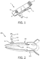
- Fig 1 shows a conventional limb clamp 1 for an ECG device.
- the limb clamp 1 generally comprises a first clamp portion 3, a second clamp portion 5, a spring element 7 interconnecting the first clamp portion 3 and the second clamp portion 5, and a medical electrode 9 mounted at the first clamp portion 3.
- the medical electrode 9 generally comprises a conductive support cylinder 11 that is fixed relative to the first clamp portion 3.
- GB2353417 shows exemplary connectors and strap clips of muscle toner pads.
- CN201691920U and CN201312804Y show conventional limb electrode clamps.
- the present invention provides a medical electrode as claimed in claim 1, a medical electrode as claimed in claim 2, and a medical electrode as claimed in claim 4.
- the present invention provides a limb clamp for an ECG device as claimed in claim 8.
- FIG. 2 is an exploded perspective view of a limb clamp for the ECG device with a medical electrode according to a first embodiment of the present invention.
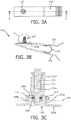
- FIG. 3A is a top view of the limb clamp of FIG 2 in an assembled state.
- FIG. 3B is a cross sectional view taken along a line A-A of FIG. 3A.
- FIG. 3C is an enlarged view of an encircled portion A of FIG. 3B .
- the limb clamp for the ECG device with a medical electrode according to a first embodiment of the present invention is generally designated by reference numeral 100.
- the limb clamp 100 for the ECG generally comprises a first clamp portion 101, a second clamp portion 103, a spring element 105 interconnecting the first clamp portion 101 and the second clamp portion 105, and a medical electrode 107 mounted at the first clamp portion 101.
- the structure and the connection of the first clamp portion 101, the second clamp portion 103 and the spring element 105 are known in the art.
- the medical electrode 107 generally comprises a conductive metal base 109 and a conductive support cylinder 111.
- the conductive metal base 109 comprises a plate element 109a and a boss 109b formed on the plate element 109a.
- the lower surface of the plate element 109a contacts the body of a patient.
- an electrolyte gel may be applied to the lower surface of the plate element 109a.
- the boss 109b is shown to be formed integrally with the plate element 109a, the boss 109b may be formed separately from and attached to the plate element 109a in a known way, for example, by means of gluing, welding, or a thread connection.
- a recess 109c is formed in the boss 109b.
- the conductive support cylinder 111 is shown to be substantially cylindrical in shape, it may be in any suitable shape.
- the conductive support cylinder 111 may comprise a through hole 111a transverse to its longitudinal axis for receiving a cable.
- the conductive support cylinder 111 further comprises a threaded hole 111b formed along its longitudinal axis and communicating with the through hole 111a.
- a thumb screw 113 may be screwed into the threaded hole 111b to keep the cable in place in a reliable manner.
- the conductive support cylinder 111 does not have the through hole 111a and the threaded hole 111b. In this case, the cable is attached to the conductive support cylinder 111 directly or by means of a sheath.
- a bearing 115 made from a conductive material is disposed within the recess 109c formed in the boss 109b.
- the lower end of the conductive support cylinder 111 is mounted into the bearing 115 so that the conductive support cylinder 111 may rotate relative to the conductive metal base 109.
- the lower end of the conductive support cylinder 111 is shown to be thinner than the other portion of the conductive support cylinder 111, the lower end of the conductive support cylinder 111 may be as thick as or thicker than the other portion of the conductive support cylinder 111.
- the bearing 115 is disposed within the recess 109c formed in the boss 109b.
- the bearing 115 alternatively may be disposed within a recess formed in the lower end of the conductive support cylinder 111. In this case, the upper end of the boss 109b is mounted into the bearing 115.
- the conductive bearing 115 allows the conductive support cylinder 111 to be rotatable relative to the boss 109b while keeping the conductive support cylinder 111 in electrical communication with the boss 109b.
- An outer thread 109d is formed on an outer surface of the boss 109b.
- the boss 109b may pass through a through hole 101a formed in the first clamp portion 101 and then a nut 117 may be screwed onto the outer thread 109d of the boss 109b so that the medical electrode 107 is mounted onto the first clamp portion 101.
- FIGS. 4A-4C illustrates a limb clamp for the ECG device with a medical electrode according to a second embodiment of the present invention.
- FIG. 4A is a cross sectional view similar to FIG. 3B .
- FIG. 4B is an enlarged view of an encircled portion A of FIG. 4A.
- FIG. 4C is a perspective view of a support cylinder shown in FIG. 4B .
- the limb clamp for the ECG device with a medical electrode according to a second embodiment of the present invention is generally designated by reference numeral 200.
- Parts of the limb clamp for the ECG device with the medical electrode according to the second embodiment corresponding to parts of the limb clamp for the ECG device with the medical electrode according to the first embodiment are indicated by the same reference numerals, plus "100". The description for the same parts is omitted for simplicity.
- the limb clamp 200 for the ECG device with a medical electrode according to the second embodiment is substantially similar to the limb clamp 100 for the ECG device with the medical electrode according to the first embodiment, but does not include the bearing 115.
- a plurality of conductive and elastic strips 211c extending along the longitudinal axis of the conductive support cylinder 211 and projecting radially outward are disposed on the circumferential surface of the lower end of the conductive support cylinder 211.
- the lower end of the conductive support cylinder 211 is inserted snugly into the recess 209c formed in the boss 209b.
- the elasticity of the elastic strips 211c allows the conductive support cylinder 211 to be rotatable relative to the boss 209b, while keeping the conductive support cylinder 211 in electrical communication with the boss 209b.
- the plurality of conductive and elastic strips 211c is distributed evenly on the circumferential surface of the lower end of the conductive support cylinder 211.
- the plurality of conductive and elastic strips 211c may be formed integrally with or separately from the conductive support cylinder 211.
- a sleeve comprising the plurality of conductive and elastic strips 211c may be attached to the lower end of the conductive support cylinder 211.
- FIGS. 5A-5C illustrate an example of a limb clamp for the ECG device with a medical electrode.
- FIG. 5A is a cross sectional view similar to FIG. 3B .
- FIG. 5B is an enlarged view of an encircled portion A of FIG. 5A.
- FIG. 5C is an exploded perspective view of a medical electrode shown in FIG. 5B .
- the limb clamp for the ECG device with a medical electrode is generally designated by reference numeral 300. Parts of the limb clamp for the ECG device with the medical electrode corresponding to parts of the limb clamp for the ECG device with the medical electrode according to the first embodiment are indicated by the same reference numerals, plus "200". The description for the same parts is omitted for simplicity.
- the limb clamp 300 for the ECG device with a medical electrode is substantially similar to the limb clamp 100 for the ECG device with the medical electrode according to the first embodiment, but does not include the bearing 115.
- a universal joint knuckle is formed between the lower end of the conductive support cylinder 311 and the boss 309b.
- a spherical head 311c is formed at the lower end of the conductive support cylinder 311 and a corresponding spherical recess 309c is formed in the boss 309b. The spherical head 311c is received snugly in the spherical recess 309c to form the universal joint knuckle.
- the universal joint knuckle allows the conductive support cylinder 311 to be rotatable relative to the boss 309b, while keeping the conductive support cylinder 311 in electrical communication with the boss 309b.
- the conductive metal base 309 may comprise a first half portion 309d and a second half portion 309e.
- FIGS. 6A-6C illustrate a limb clamp for the ECG device with a medical electrode according to another embodiment of the present invention.
- FIG. 6A is a cross sectional view similar to FIG. 3B .
- FIG. 6B is an enlarged view of an encircled portion A of FIG. 6A.
- FIG. 6C is an exploded perspective view of a medical electrode shown in FIG. 6B .
- the limb clamp for the ECG device with a medical electrode according to this embodiment of the present invention is generally designated by reference numeral 400.
- Parts of the limb clamp for the ECG device with the medical electrode according to this embodiment corresponding to parts of the limb clamp for the ECG device with the medical electrode according to the first embodiment are indicated by the same reference numerals, plus "300". The description for the same parts is omitted for simplicity.
- the limb clamp 400 for the ECG device with a medical electrode is substantially similar to the limb clamp 100 for the ECG device with the medical electrode according to the first embodiment, but does not include the bearing 115.
- a flange 411c is formed on the outer surface of the conductive support cylinder 411.
- a conductive spring 419 is disposed between the flange 411c and the boss 409b.
- the nut 417 having an inner flange 417a may be used to mount the conductive support cylinder 411 to the conductive metal base 409 and fix the metal electrode 407 to the first clamp portion 401.
- the conductive spring 419 allows the conductive support cylinder 411 to be rotatable relative to the boss 409b, while keeping the conductive support cylinder 411 in electrical communication with the boss 409b.
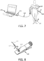
- FIG. 7 is a schematic view showing that the medical electrodes 107 and the limb clamps 100 according to the present invention connect with an ECG module 121 via the respective cables 123 and are applied to the patient to record ECG signals.
- the other pair of limb clamps 100 are not shown for simplicity.
- the medical electrodes according to the present invention are applied to the patient's torso as torso electrodes, they are attached to the patient's torso by an adhesive plaster or a suction cup.
- the ECG module 121 connects with a computer 125 to show and analyze the recorded ECG signals.
- FIG. 8 is a perspective view of a limb clamp for the ECG device according to the present invention showing no bending of the cable connecting with the electrode of the limb clamp.
- a cable post 127 connecting with the cable 123 is inserted into the through hole 111a of the conductive support cylinder 111 of the medical electrode 107. Because the conductive support cylinder 111 of the medical electrode 107 may rotate relative to the conductive metal base 109 of the medical electrode 107, the cable 123 also rotates with the conductive support cylinder 111 as shown by a double-arrow line. Thus, no bending of the cable 123 connecting with the medical electrode 107 occurs irrespective of how the medical electrodes and the limb clamps move, thereby avoiding any cable failure.
- the medical electrodes and the limb clamps are the medical electrodes 107 and the limb clamps 100 according to the first embodiment of the present invention.
- the medical electrodes and the limb clamps may be the medical electrodes and the limb clamps according to any one of the other embodiments of the present invention.
Description
- The invention relates to an improved medical electrode, in particular to a medical electrode and a limb clamp for an ECG (electrocardiogram) device comprising such a medical electrode.
- An ECG device is widely used to obtain medical (i.e. biopotential) signals containing information indicative of electrical activity associated with the heart and pulmonary system. The signals obtained are one of the important bases for some disease diagnosis. The ECG device generally comprises a plurality (for example six) of torso electrodes which are applied to a torso portion of a patient and two pairs of limb electrodes which are mounted on a respective limp clamp and applied to the left and right limbs of the patient, respectively. These electrodes connect with an ECG module via the respective cables. In use, cable failure often occurs because of excessive bending cycles caused by various factors such as inappropriate placement of the electrodes, movement of the patient's body and/or their use model. Especially the cables connecting with the limb electrodes are easier subject to cable failure due to their unique use model.
-
Fig 1 shows aconventional limb clamp 1 for an ECG device. Thelimb clamp 1 generally comprises a first clamp portion 3, asecond clamp portion 5, aspring element 7 interconnecting the first clamp portion 3 and thesecond clamp portion 5, and a medical electrode 9 mounted at the first clamp portion 3. The medical electrode 9 generally comprises aconductive support cylinder 11 that is fixed relative to the first clamp portion 3. When acable 13 is inserted into and fixed to thesupport cylinder 11 of the medical electrode 9 that is fixed relative to the first clamp portion 3, the movement of the medical electrode 3 directly results in bending of therespective cable 1, thereby possibly causing cable failure. Further, it is possible for the left and right limb clamps to be applied reversely to the right and left limbs, which causes worse bending of the respective cables as shown inFig 1 and thus results in cable failure. Cable failure contributes to wrong or inaccurate signals, which in turn result in wrong or inaccurate diagnosis. Replacing a failed cable not only increases total cost of ownership for the ECG device but also is a waste of time and causes the ECG device to be out of service for a period of time. All in all, this issue has a big impact on the ECG industry all the time. - Past efforts focused primarily on increasing the durability of the cable itself, for example, thickening the lead wire of the cable, which further increases the cost of the ECG device and makes the patient feel uncomfortable.
-
GB2353417 CN201691920U andCN201312804Y show conventional limb electrode clamps. - Thus, there is a need to make improvements on the conventional medical electrode.
- Accordingly, it is desirable to provide a medical electrode which may prevent the cable connecting with the medical electrode from flexing, thereby avoiding cable failure. In accordance with this first aspect, the present invention provides a medical electrode as claimed in
claim 1, a medical electrode as claimed in claim 2, and a medical electrode as claimed in claim 4. - It is also desirable to provide a limb clamp for an ECG device which may prevent the cable connecting with an electrode of the limb clamp from flexing, thereby avoiding cable failure. In accordance with this second aspect, the present invention provides a limb clamp for an ECG device as claimed in claim 8.
- These and other objects, features and characteristics of the present invention, as well as the methods of operation and functions of the related elements of structure and the combination of parts and economies of manufacture, will become more apparent upon consideration of the following description and the appended claims with reference to the accompanying drawings, all of which form a part of this specification, wherein like reference numerals designate corresponding parts in the various figures. It is to be expressly understood, however, that the drawings are for the purpose of illustration and description only and are not intended as a definition of the limits of the invention.
-
-
FIG. 1 is a perspective view of a conventional limb clamp for the ECG device showing a bend of a cable connecting with an electrode of the limb clamp. -
FIG. 2 is an exploded perspective view of a limb clamp for the ECG device with a medical electrode according to a first embodiment of the present invention. -
FIG. 3A is a top view of the limb clamp ofFIG 2 in an assembled state. -
FIG. 3B is a cross sectional view taken along a line A-A ofFIG. 3A . -
FIG. 3C is an enlarged view of an encircled portion A ofFIG. 3B . -
FIG. 4A is a cross sectional view similar toFIG. 3B , showing a limb clamp for the ECG device with a medical electrode according to a second embodiment of the present invention. -
FIG. 4B is an enlarged view of an encircled portion A ofFIG. 4A . -
FIG. 4C is a perspective view of a support cylinder shown inFIG. 4B . -
FIG. 5A is a cross sectional view similar toFIG. 3B , showing an example of a limb clamp for the ECG device with a medical electrode. -
FIG. 5B is an enlarged view of an encircled portion A ofFIG. 5A . -
FIG. 5C is an exploded perspective view of a medical electrode shown inFIG. 5B . -
FIG. 6A is a cross sectional view similar toFIG. 3B , showing a limb clamp for the ECG device with a medical electrode according to another embodiment of the present invention. -
FIG. 6B is an enlarged view of an encircled portion A ofFIG. 6A . -
FIG. 6C is an exploded perspective view of a medical electrode shown inFIG. 6B . -
FIG. 7 is a schematic view showing that the medical electrodes and the limb clamps according to the present invention connect with an ECG module via the respective cables and are applied to the patient to record ECG signals. -
FIG. 8 is a perspective view of a limb clamp for the ECG device according to the present invention showing that there is no bending of the cable connecting with the electrode of the limb clamp. - The preferred embodiments of the present invention will be described in detail with reference to the drawings.
-
FIG. 2 is an exploded perspective view of a limb clamp for the ECG device with a medical electrode according to a first embodiment of the present invention.FIG. 3A is a top view of the limb clamp ofFIG 2 in an assembled state.FIG. 3B is a cross sectional view taken along a line A-A ofFIG. 3A. FIG. 3C is an enlarged view of an encircled portion A ofFIG. 3B . The limb clamp for the ECG device with a medical electrode according to a first embodiment of the present invention is generally designated byreference numeral 100. As shown inFIGS 2 ,3A, 3B and 3C , thelimb clamp 100 for the ECG generally comprises afirst clamp portion 101, asecond clamp portion 103, aspring element 105 interconnecting thefirst clamp portion 101 and thesecond clamp portion 105, and amedical electrode 107 mounted at thefirst clamp portion 101. The structure and the connection of thefirst clamp portion 101, thesecond clamp portion 103 and thespring element 105 are known in the art. - The
medical electrode 107 according to the first embodiment of the present invention generally comprises aconductive metal base 109 and aconductive support cylinder 111. Theconductive metal base 109 comprises aplate element 109a and aboss 109b formed on theplate element 109a. In use, the lower surface of theplate element 109a contacts the body of a patient. Of course, an electrolyte gel may be applied to the lower surface of theplate element 109a. Although theboss 109b is shown to be formed integrally with theplate element 109a, theboss 109b may be formed separately from and attached to theplate element 109a in a known way, for example, by means of gluing, welding, or a thread connection. Arecess 109c is formed in theboss 109b. Although theconductive support cylinder 111 is shown to be substantially cylindrical in shape, it may be in any suitable shape. Theconductive support cylinder 111 may comprise a throughhole 111a transverse to its longitudinal axis for receiving a cable. Preferably, theconductive support cylinder 111 further comprises a threadedhole 111b formed along its longitudinal axis and communicating with the throughhole 111a. When a cable is inserted into the throughhole 111a, athumb screw 113 may be screwed into the threadedhole 111b to keep the cable in place in a reliable manner. Of course, it is also feasible that theconductive support cylinder 111 does not have the throughhole 111a and the threadedhole 111b. In this case, the cable is attached to theconductive support cylinder 111 directly or by means of a sheath. - A bearing 115 made from a conductive material is disposed within the
recess 109c formed in theboss 109b. The lower end of theconductive support cylinder 111 is mounted into the bearing 115 so that theconductive support cylinder 111 may rotate relative to theconductive metal base 109. Although the lower end of theconductive support cylinder 111 is shown to be thinner than the other portion of theconductive support cylinder 111, the lower end of theconductive support cylinder 111 may be as thick as or thicker than the other portion of theconductive support cylinder 111. In the shown embodiment, thebearing 115 is disposed within therecess 109c formed in theboss 109b. It should be understood that the bearing 115 alternatively may be disposed within a recess formed in the lower end of theconductive support cylinder 111. In this case, the upper end of theboss 109b is mounted into thebearing 115. Theconductive bearing 115 allows theconductive support cylinder 111 to be rotatable relative to theboss 109b while keeping theconductive support cylinder 111 in electrical communication with theboss 109b. - An
outer thread 109d is formed on an outer surface of theboss 109b. Theboss 109b may pass through a throughhole 101a formed in thefirst clamp portion 101 and then anut 117 may be screwed onto theouter thread 109d of theboss 109b so that themedical electrode 107 is mounted onto thefirst clamp portion 101. -
FIGS. 4A-4C illustrates a limb clamp for the ECG device with a medical electrode according to a second embodiment of the present invention.FIG. 4A is a cross sectional view similar toFIG. 3B .FIG. 4B is an enlarged view of an encircled portion A ofFIG. 4A. FIG. 4C is a perspective view of a support cylinder shown inFIG. 4B . The limb clamp for the ECG device with a medical electrode according to a second embodiment of the present invention is generally designated byreference numeral 200. Parts of the limb clamp for the ECG device with the medical electrode according to the second embodiment corresponding to parts of the limb clamp for the ECG device with the medical electrode according to the first embodiment are indicated by the same reference numerals, plus "100". The description for the same parts is omitted for simplicity. - The
limb clamp 200 for the ECG device with a medical electrode according to the second embodiment is substantially similar to thelimb clamp 100 for the ECG device with the medical electrode according to the first embodiment, but does not include thebearing 115. In this embodiment, a plurality of conductive andelastic strips 211c extending along the longitudinal axis of theconductive support cylinder 211 and projecting radially outward are disposed on the circumferential surface of the lower end of theconductive support cylinder 211. The lower end of theconductive support cylinder 211 is inserted snugly into therecess 209c formed in theboss 209b. The elasticity of theelastic strips 211c allows theconductive support cylinder 211 to be rotatable relative to theboss 209b, while keeping theconductive support cylinder 211 in electrical communication with theboss 209b. Preferably, the plurality of conductive andelastic strips 211c is distributed evenly on the circumferential surface of the lower end of theconductive support cylinder 211. Further, the plurality of conductive andelastic strips 211c may be formed integrally with or separately from theconductive support cylinder 211. For example, a sleeve comprising the plurality of conductive andelastic strips 211c may be attached to the lower end of theconductive support cylinder 211. -
FIGS. 5A-5C illustrate an example of a limb clamp for the ECG device with a medical electrode.FIG. 5A is a cross sectional view similar toFIG. 3B .FIG. 5B is an enlarged view of an encircled portion A ofFIG. 5A. FIG. 5C is an exploded perspective view of a medical electrode shown inFIG. 5B . The limb clamp for the ECG device with a medical electrode is generally designated byreference numeral 300. Parts of the limb clamp for the ECG device with the medical electrode corresponding to parts of the limb clamp for the ECG device with the medical electrode according to the first embodiment are indicated by the same reference numerals, plus "200". The description for the same parts is omitted for simplicity. - The
limb clamp 300 for the ECG device with a medical electrode is substantially similar to thelimb clamp 100 for the ECG device with the medical electrode according to the first embodiment, but does not include thebearing 115. In this embodiment, a universal joint knuckle is formed between the lower end of theconductive support cylinder 311 and theboss 309b. Specifically, aspherical head 311c is formed at the lower end of theconductive support cylinder 311 and a correspondingspherical recess 309c is formed in theboss 309b. Thespherical head 311c is received snugly in thespherical recess 309c to form the universal joint knuckle. The universal joint knuckle allows theconductive support cylinder 311 to be rotatable relative to theboss 309b, while keeping theconductive support cylinder 311 in electrical communication with theboss 309b. To allow easy assembly of themedical electrode 307, theconductive metal base 309 may comprise afirst half portion 309d and asecond half portion 309e. -
FIGS. 6A-6C illustrate a limb clamp for the ECG device with a medical electrode according to another embodiment of the present invention.FIG. 6A is a cross sectional view similar toFIG. 3B .FIG. 6B is an enlarged view of an encircled portion A ofFIG. 6A. FIG. 6C is an exploded perspective view of a medical electrode shown inFIG. 6B . The limb clamp for the ECG device with a medical electrode according to this embodiment of the present invention is generally designated byreference numeral 400. Parts of the limb clamp for the ECG device with the medical electrode according to this embodiment corresponding to parts of the limb clamp for the ECG device with the medical electrode according to the first embodiment are indicated by the same reference numerals, plus "300". The description for the same parts is omitted for simplicity. - The
limb clamp 400 for the ECG device with a medical electrode is substantially similar to thelimb clamp 100 for the ECG device with the medical electrode according to the first embodiment, but does not include thebearing 115. In this embodiment, aflange 411c is formed on the outer surface of theconductive support cylinder 411. When the lower end of theconductive support cylinder 411 is inserted loosely into therecess 409c formed in theboss 409b, aconductive spring 419 is disposed between theflange 411c and theboss 409b. Further, thenut 417 having aninner flange 417a may be used to mount theconductive support cylinder 411 to theconductive metal base 409 and fix themetal electrode 407 to thefirst clamp portion 401. Theconductive spring 419 allows theconductive support cylinder 411 to be rotatable relative to theboss 409b, while keeping theconductive support cylinder 411 in electrical communication with theboss 409b. -
FIG. 7 is a schematic view showing that themedical electrodes 107 and the limb clamps 100 according to the present invention connect with anECG module 121 via therespective cables 123 and are applied to the patient to record ECG signals. The other pair of limb clamps 100 are not shown for simplicity. When the medical electrodes according to the present invention are applied to the patient's torso as torso electrodes, they are attached to the patient's torso by an adhesive plaster or a suction cup. TheECG module 121 connects with acomputer 125 to show and analyze the recorded ECG signals.FIG. 8 is a perspective view of a limb clamp for the ECG device according to the present invention showing no bending of the cable connecting with the electrode of the limb clamp. Acable post 127 connecting with thecable 123 is inserted into the throughhole 111a of theconductive support cylinder 111 of themedical electrode 107. Because theconductive support cylinder 111 of themedical electrode 107 may rotate relative to theconductive metal base 109 of themedical electrode 107, thecable 123 also rotates with theconductive support cylinder 111 as shown by a double-arrow line. Thus, no bending of thecable 123 connecting with themedical electrode 107 occurs irrespective of how the medical electrodes and the limb clamps move, thereby avoiding any cable failure. - In
FIGS. 7 and 8 , as an example, the medical electrodes and the limb clamps are themedical electrodes 107 and the limb clamps 100 according to the first embodiment of the present invention. Obviously, the medical electrodes and the limb clamps may be the medical electrodes and the limb clamps according to any one of the other embodiments of the present invention. - While the medical electrode according to the present invention is explained as a part of the ECG device in the embodiments, it should be understood that the medical electrode may be used with other medical instruments and may comprise additional components for other functions. Although the invention has been described in detail for the purpose of illustration based on what are currently considered to be the most practical and preferred embodiments, it is to be understood that such detail is solely for that purpose and that the invention is not limited to the disclosed embodiments, but on the contrary, is intended to cover modifications and equivalent arrangements that are within the scope of the appended claims.
Claims (10)
- A medical electrode (107) comprising:a conductive metal base (109) comprising a plate element (109a) and a boss (109b) formed on the plate element (109a); anda conductive support cylinder (111) separate from the conductive metal base (109);wherein the conductive support cylinder (111) is rotatably mounted to the conductive metal base (109), while remaining in electrical communication with the conductive metal base (109);wherein a recess (109c) is formed in the boss (109b) and a lower end of the conductive support cylinder (111) is rotatably mounted into the recess (109c);wherein a conductive bearing (115) is disposed within the recess (109c) and the lower end of the conductive support cylinder (111) is mounted into the conductive bearing (115) to allow the conductive cylinder to be rotatable relative to the boss while remaining in electrical communication with the boss (109b).
- A medical electrode (207) comprising:a conductive metal base (209) comprising a plate element (209a) and a boss (209b) formed on the plate element (209a); anda conductive support cylinder (211) separate from the conductive metal base (209);wherein the conductive support cylinder (211) is rotatably mounted to the conductive metal base (209), while remaining in electrical communication with the conductive metal base (209);wherein a recess (209c) is formed in the boss (209b) and a lower end of the conductive support cylinder (211) is rotatably mounted into the recess (209c);wherein a plurality of conductive and elastic strips (211c) extending along the longitudinal axis of the conductive support cylinder (211) and projecting radially outward are disposed on the circumferential surface of the lower end of the conductive support cylinder (211) and the lower end of the conductive support cylinder (211) is inserted snugly into the recess (209c), and the elasticity of the elastic strips is configured to allow the conductive support cylinder to be rotatable relative to the boss while remaining in electrical communication with the boss (209b).
- The medical electrode (207) according to claim 2, wherein the plurality of conductive and elastic strips (211c) are evenly distributed on the circumferential surface of the lower end of the conductive support cylinder (211).
- A medical electrode (407) comprising:a conductive metal base (409) comprising a plate element (409a) and a boss (409b) formed on the plate element (409a); anda conductive support cylinder (411) separate from the conductive metal base (409);wherein the conductive support cylinder (411) is rotatably mounted to the conductive metal base (409), while remaining in electrical communication with the conductive metal base (409);wherein a recess (409c) is formed in the boss (409b) and a lower end of the conductive support cylinder (411) is rotatably mounted into the recess (409c);wherein a flange (411c) is formed on an outer surface of the conductive support cylinder (411), a conductive spring (419) is disposed between the flange (411c) and the boss (409b), a nut (417) having an inner flange (417a) is screwed to the boss (409b) to mount the conductive support cylinder (411) to the conductive metal base (409);wherein the conductive spring (419) is configured to allow the conductive support cylinder to be rotatable relative to the boss while remaining in electrical communication with the boss (409b).
- The medical electrode (107, 207, 407) according to claim 1, 2 or 4, further comprising an electrolyte gel applied to the lower surface of the plate element (109a, 209a, 409a).
- The medical electrode (107, 207, 407) according to claim 1, 2 or 4, wherein the conductive support cylinder (111, 211, 411) comprises a through hole (111a, 211a, 411a) transverse to its longitudinal axis for receiving a cable.
- The medical electrode (107, 207, 407) according to claim 6, wherein the conductive support cylinder (111, 211, 411) further comprises a threaded hole (111b, 211b, 411b) formed along its longitudinal axis and communicating with the through hole (111a, 211a, 411a).
- A limb clamp (100, 200, 400) for an ECG device comprising:a first clamp portion (101, 201, 401);a second clamp portion (103, 203, 403);a spring element (105, 205, 405) connecting the first clamp portion (101, 201, 401) and the second clamp portion (105, 205, 405); anda medical electrode (107, 207, 407) according to any one of claims 1 to 7 mounted at the first clamp portion (101, 201, 401).
- The limb clamp (100, 200, 400) for an ECG device according to claim 8, wherein an outer thread (109d, 209d, 409d) is formed on the outer surface of the boss (109b, 209b, 409b), the boss (109b, 209b, 409b) passes through a through hole (101a, 201a, 401a) formed in the first clamp portion (101, 201, 401) and a nut (117, 217, 417) is screwed onto the outer thread (109d, 209d, 409d) so that the medical electrode (107, 207, 407) is mounted onto the first clamp portion (101, 201, 401).
- The limb clamp (100, 200, 400) for an ECG device according to claim 9, wherein the nut for mounting the medical electrode (407) onto the first clamp portion (401) and the nut for mounting the conductive support cylinder (411) to the conductive metal base (409) are the same nut when the medical electrode is a medical electrode (407) according to claim 4.
Applications Claiming Priority (2)
| Application Number | Priority Date | Filing Date | Title |
|---|---|---|---|
| PCT/CN2013/076906 WO2014194511A2 (en) | 2013-06-07 | 2013-06-07 | Medical electrode and limb clamp for an ecg device |
| PCT/IB2014/061829 WO2014195835A1 (en) | 2013-06-07 | 2014-05-30 | Medical electrode and limb clamp for an ecg device |
Publications (2)
| Publication Number | Publication Date |
|---|---|
| EP3003463A1 EP3003463A1 (en) | 2016-04-13 |
| EP3003463B1 true EP3003463B1 (en) | 2019-07-10 |
Family
ID=51022924
Family Applications (1)
| Application Number | Title | Priority Date | Filing Date |
|---|---|---|---|
| EP14733710.9A Active EP3003463B1 (en) | 2013-06-07 | 2014-05-30 | Medical electrode and limb clamp for an ecg device |
Country Status (6)
| Country | Link |
|---|---|
| US (2) | US10182731B2 (en) |
| EP (1) | EP3003463B1 (en) |
| JP (1) | JP6449863B2 (en) |
| BR (1) | BR112015030249A2 (en) |
| RU (1) | RU2676448C2 (en) |
| WO (2) | WO2014194511A2 (en) |
Families Citing this family (4)
| Publication number | Priority date | Publication date | Assignee | Title |
|---|---|---|---|---|
| CN105167768B (en) * | 2015-07-10 | 2018-08-21 | 深圳迪美泰数字医学技术有限公司 | A kind of electrode holder |
| CN105380641B (en) * | 2015-12-11 | 2018-12-07 | 北京五维康科技有限公司 | A kind of hand-held cardiovascular health monitoring device |
| US10117593B2 (en) * | 2016-08-04 | 2018-11-06 | Zentan Technology Co., Ltd. | Physiological signal detection clamp |
| US11607173B2 (en) * | 2019-05-24 | 2023-03-21 | Nikomed USA, Inc. | Medical electrode connector for printed lead wires |
Family Cites Families (24)
| Publication number | Priority date | Publication date | Assignee | Title |
|---|---|---|---|---|
| US2815749A (en) * | 1953-11-30 | 1957-12-10 | Nathan H Friedman | Electrocardiographic contact attachment |
| US3067749A (en) * | 1961-02-27 | 1962-12-11 | Max L Walters | Electrode limb clamps |
| US3498291A (en) * | 1966-02-10 | 1970-03-03 | Lockheed Aircraft Corp | Body signal sensing electrode apparatus |
| JPS4831661Y1 (en) * | 1968-10-23 | 1973-09-27 | ||
| JPS4831661B1 (en) | 1970-09-10 | 1973-10-01 | ||
| US4033333A (en) * | 1975-12-10 | 1977-07-05 | Combined Scientific Resources Corporation | Electrode arrangement for taking electrocardiograms |
| EP0101870A3 (en) * | 1982-08-05 | 1986-09-17 | Kontron-Holding Ag | Portable electrocardiologic apparatus |
| JPS60166306U (en) * | 1984-04-12 | 1985-11-05 | フクダ電子株式会社 | Clip-type electrode for electrocardiograph |
| JPS60166307U (en) * | 1984-04-12 | 1985-11-05 | フクダ電子株式会社 | Clip-type electrode for electrocardiograph |
| DK150841C (en) * | 1984-12-19 | 1988-07-11 | Medicotest Systemer As | CONNECTOR FOR ESTABLISHING ELECTRICAL CONNECTION WITH A disposable skin electrode |
| FR2657520B1 (en) * | 1990-01-31 | 1994-05-13 | Espinasse Francoise | ELECTRODE CHARACTERIZED BY TWO CONDUCTIVE PLATES TO BE PLACED ON A SINGLE LOWER MEMBER FOR THE PRODUCTION OF THE ELECTROCARDIOGRAM. |
| US5823832A (en) * | 1996-12-23 | 1998-10-20 | Netech Corporation | Electrical connector for use with an electroencephalograph electrode |
| JP3547922B2 (en) * | 1996-12-25 | 2004-07-28 | 日東電工株式会社 | Limb lead electrode pad |
| GB9919682D0 (en) * | 1999-08-19 | 1999-10-20 | Dezac Limited | Improvements relating to muscle toner pads |
| US6885548B2 (en) * | 2002-04-17 | 2005-04-26 | Medtronic, Inc. | Methods of fabricating anode layers of flat electrolytic capacitors |
| RU2297211C2 (en) * | 2005-04-25 | 2007-04-20 | Государственное образовательное учреждение высшего профессионального образования Санкт-Петербургская государственная медицинская академия им. И.И. Мечникова | Electrode for carrying out nonivasive electroacupuncture with d'arsonval currents |
| JP4831661B2 (en) | 2005-09-22 | 2011-12-07 | 田中貴金属工業株式会社 | Water-cooled crucible used in levitation melting casting |
| US8406843B2 (en) | 2008-04-04 | 2013-03-26 | Mark Tiegs | ECG monitoring electrode |
| CN201312804Y (en) * | 2008-12-18 | 2009-09-23 | 深圳市理邦精密仪器有限公司 | Novel limb electrode |
| CN201591552U (en) * | 2010-01-22 | 2010-09-29 | 深圳市理邦精密仪器有限公司 | Multifunctional clip for livestock |
| JP5812681B2 (en) * | 2010-05-19 | 2015-11-17 | アークレイ株式会社 | Electrochemical sensor |
| CN201691920U (en) * | 2010-06-22 | 2011-01-05 | 深圳市理邦精密仪器股份有限公司 | Signal transmission structure without weld contact |
| US8958878B2 (en) | 2010-09-17 | 2015-02-17 | Michael Cejnar | Low profile adapter for continuous connection of pacemaker lead during implantation |
| US9841784B2 (en) | 2014-09-26 | 2017-12-12 | Intel Corporation | Apparatus and method for controlling wearable devices using wireless energy harvesting |
-
2013
- 2013-06-07 WO PCT/CN2013/076906 patent/WO2014194511A2/en active Application Filing
-
2014
- 2014-05-30 JP JP2016517709A patent/JP6449863B2/en active Active
- 2014-05-30 BR BR112015030249A patent/BR112015030249A2/en not_active Application Discontinuation
- 2014-05-30 US US14/895,250 patent/US10182731B2/en active Active
- 2014-05-30 WO PCT/IB2014/061829 patent/WO2014195835A1/en active Application Filing
- 2014-05-30 RU RU2015156416A patent/RU2676448C2/en not_active IP Right Cessation
- 2014-05-30 EP EP14733710.9A patent/EP3003463B1/en active Active
-
2018
- 2018-12-12 US US16/217,236 patent/US10779742B2/en active Active
Non-Patent Citations (1)
| Title |
|---|
| None * |
Also Published As
| Publication number | Publication date |
|---|---|
| JP2016523129A (en) | 2016-08-08 |
| US20190110712A1 (en) | 2019-04-18 |
| WO2014195835A1 (en) | 2014-12-11 |
| JP6449863B2 (en) | 2019-01-09 |
| RU2676448C2 (en) | 2018-12-28 |
| US10779742B2 (en) | 2020-09-22 |
| EP3003463A1 (en) | 2016-04-13 |
| RU2015156416A (en) | 2017-07-20 |
| BR112015030249A2 (en) | 2017-07-25 |
| US10182731B2 (en) | 2019-01-22 |
| WO2014194511A2 (en) | 2014-12-11 |
| US20160128600A1 (en) | 2016-05-12 |
Similar Documents
| Publication | Publication Date | Title |
|---|---|---|
| US10779742B2 (en) | Medical electrode and limb clamp for an ECG device | |
| US8123576B2 (en) | Connecting structure of snap electrode and electric wire | |
| JP6077639B2 (en) | Transducer assembly | |
| US10631747B2 (en) | Measurement patch device | |
| US5626135A (en) | Medical electrode | |
| US8251736B2 (en) | Connector assembly for connecting an electrical lead to an electrode | |
| CN106470602B (en) | Medical electrode | |
| EP2339696A1 (en) | Electrical connector assembly | |
| US20190000338A1 (en) | Method and system for obtaining signals from dry eeg electrodes | |
| EP2777495A1 (en) | Reduce motion artifact electrode | |
| US9237857B2 (en) | Device for applying electrode assemblies | |
| US7277743B2 (en) | Patient monitoring system | |
| US7379768B2 (en) | Medical electrode and method of use | |
| CN105263565B (en) | Electrode for medical service and the limbs fixture for ECG device | |
| US20230066856A1 (en) | Dry Electrode And Wearable Device | |
| JP6802730B2 (en) | Electrodes for measuring biological information | |
| JPS637202Y2 (en) | ||
| JP2022080763A (en) | Electrode structure | |
| US20150327788A1 (en) | Electrode lead wire connector | |
| WO2021099952A1 (en) | Electrode for recording electroencephalographic signals and/or stimulating patients | |
| CN111096739A (en) | Rotary connection type wire connector |
Legal Events
| Date | Code | Title | Description |
|---|---|---|---|
| PUAI | Public reference made under article 153(3) epc to a published international application that has entered the european phase |
Free format text: ORIGINAL CODE: 0009012 |
|
| 17P | Request for examination filed |
Effective date: 20160107 |
|
| AK | Designated contracting states |
Kind code of ref document: A1 Designated state(s): AL AT BE BG CH CY CZ DE DK EE ES FI FR GB GR HR HU IE IS IT LI LT LU LV MC MK MT NL NO PL PT RO RS SE SI SK SM TR |
|
| AX | Request for extension of the european patent |
Extension state: BA ME |
|
| DAX | Request for extension of the european patent (deleted) | ||
| STAA | Information on the status of an ep patent application or granted ep patent |
Free format text: STATUS: EXAMINATION IS IN PROGRESS |
|
| 17Q | First examination report despatched |
Effective date: 20161223 |
|
| GRAP | Despatch of communication of intention to grant a patent |
Free format text: ORIGINAL CODE: EPIDOSNIGR1 |
|
| RIN1 | Information on inventor provided before grant (corrected) |
Inventor name: SU, JIE Inventor name: ZHU, YUANCHAO |
|
| STAA | Information on the status of an ep patent application or granted ep patent |
Free format text: STATUS: GRANT OF PATENT IS INTENDED |
|
| INTG | Intention to grant announced |
Effective date: 20190124 |
|
| GRAS | Grant fee paid |
Free format text: ORIGINAL CODE: EPIDOSNIGR3 |
|
| GRAA | (expected) grant |
Free format text: ORIGINAL CODE: 0009210 |
|
| STAA | Information on the status of an ep patent application or granted ep patent |
Free format text: STATUS: THE PATENT HAS BEEN GRANTED |
|
| AK | Designated contracting states |
Kind code of ref document: B1 Designated state(s): AL AT BE BG CH CY CZ DE DK EE ES FI FR GB GR HR HU IE IS IT LI LT LU LV MC MK MT NL NO PL PT RO RS SE SI SK SM TR |
|
| REG | Reference to a national code |
Ref country code: GB Ref legal event code: FG4D |
|
| REG | Reference to a national code |
Ref country code: CH Ref legal event code: EP Ref country code: AT Ref legal event code: REF Ref document number: 1152878 Country of ref document: AT Kind code of ref document: T Effective date: 20190715 |
|
| REG | Reference to a national code |
Ref country code: DE Ref legal event code: R096 Ref document number: 602014049817 Country of ref document: DE |
|
| REG | Reference to a national code |
Ref country code: IE Ref legal event code: FG4D |
|
| REG | Reference to a national code |
Ref country code: NL Ref legal event code: MP Effective date: 20190710 |
|
| REG | Reference to a national code |
Ref country code: LT Ref legal event code: MG4D |
|
| REG | Reference to a national code |
Ref country code: AT Ref legal event code: MK05 Ref document number: 1152878 Country of ref document: AT Kind code of ref document: T Effective date: 20190710 |
|
| PG25 | Lapsed in a contracting state [announced via postgrant information from national office to epo] |
Ref country code: HR Free format text: LAPSE BECAUSE OF FAILURE TO SUBMIT A TRANSLATION OF THE DESCRIPTION OR TO PAY THE FEE WITHIN THE PRESCRIBED TIME-LIMIT Effective date: 20190710 Ref country code: PT Free format text: LAPSE BECAUSE OF FAILURE TO SUBMIT A TRANSLATION OF THE DESCRIPTION OR TO PAY THE FEE WITHIN THE PRESCRIBED TIME-LIMIT Effective date: 20191111 Ref country code: NL Free format text: LAPSE BECAUSE OF FAILURE TO SUBMIT A TRANSLATION OF THE DESCRIPTION OR TO PAY THE FEE WITHIN THE PRESCRIBED TIME-LIMIT Effective date: 20190710 Ref country code: LT Free format text: LAPSE BECAUSE OF FAILURE TO SUBMIT A TRANSLATION OF THE DESCRIPTION OR TO PAY THE FEE WITHIN THE PRESCRIBED TIME-LIMIT Effective date: 20190710 Ref country code: AT Free format text: LAPSE BECAUSE OF FAILURE TO SUBMIT A TRANSLATION OF THE DESCRIPTION OR TO PAY THE FEE WITHIN THE PRESCRIBED TIME-LIMIT Effective date: 20190710 Ref country code: NO Free format text: LAPSE BECAUSE OF FAILURE TO SUBMIT A TRANSLATION OF THE DESCRIPTION OR TO PAY THE FEE WITHIN THE PRESCRIBED TIME-LIMIT Effective date: 20191010 Ref country code: FI Free format text: LAPSE BECAUSE OF FAILURE TO SUBMIT A TRANSLATION OF THE DESCRIPTION OR TO PAY THE FEE WITHIN THE PRESCRIBED TIME-LIMIT Effective date: 20190710 Ref country code: SE Free format text: LAPSE BECAUSE OF FAILURE TO SUBMIT A TRANSLATION OF THE DESCRIPTION OR TO PAY THE FEE WITHIN THE PRESCRIBED TIME-LIMIT Effective date: 20190710 Ref country code: BG Free format text: LAPSE BECAUSE OF FAILURE TO SUBMIT A TRANSLATION OF THE DESCRIPTION OR TO PAY THE FEE WITHIN THE PRESCRIBED TIME-LIMIT Effective date: 20191010 |
|
| PG25 | Lapsed in a contracting state [announced via postgrant information from national office to epo] |
Ref country code: RS Free format text: LAPSE BECAUSE OF FAILURE TO SUBMIT A TRANSLATION OF THE DESCRIPTION OR TO PAY THE FEE WITHIN THE PRESCRIBED TIME-LIMIT Effective date: 20190710 Ref country code: LV Free format text: LAPSE BECAUSE OF FAILURE TO SUBMIT A TRANSLATION OF THE DESCRIPTION OR TO PAY THE FEE WITHIN THE PRESCRIBED TIME-LIMIT Effective date: 20190710 Ref country code: AL Free format text: LAPSE BECAUSE OF FAILURE TO SUBMIT A TRANSLATION OF THE DESCRIPTION OR TO PAY THE FEE WITHIN THE PRESCRIBED TIME-LIMIT Effective date: 20190710 Ref country code: ES Free format text: LAPSE BECAUSE OF FAILURE TO SUBMIT A TRANSLATION OF THE DESCRIPTION OR TO PAY THE FEE WITHIN THE PRESCRIBED TIME-LIMIT Effective date: 20190710 Ref country code: GR Free format text: LAPSE BECAUSE OF FAILURE TO SUBMIT A TRANSLATION OF THE DESCRIPTION OR TO PAY THE FEE WITHIN THE PRESCRIBED TIME-LIMIT Effective date: 20191011 Ref country code: IS Free format text: LAPSE BECAUSE OF FAILURE TO SUBMIT A TRANSLATION OF THE DESCRIPTION OR TO PAY THE FEE WITHIN THE PRESCRIBED TIME-LIMIT Effective date: 20191110 |
|
| RAP2 | Party data changed (patent owner data changed or rights of a patent transferred) |
Owner name: KONINKLIJKE PHILIPS N.V. |
|
| PG25 | Lapsed in a contracting state [announced via postgrant information from national office to epo] |
Ref country code: TR Free format text: LAPSE BECAUSE OF FAILURE TO SUBMIT A TRANSLATION OF THE DESCRIPTION OR TO PAY THE FEE WITHIN THE PRESCRIBED TIME-LIMIT Effective date: 20190710 |
|
| PG25 | Lapsed in a contracting state [announced via postgrant information from national office to epo] |
Ref country code: PL Free format text: LAPSE BECAUSE OF FAILURE TO SUBMIT A TRANSLATION OF THE DESCRIPTION OR TO PAY THE FEE WITHIN THE PRESCRIBED TIME-LIMIT Effective date: 20190710 Ref country code: RO Free format text: LAPSE BECAUSE OF FAILURE TO SUBMIT A TRANSLATION OF THE DESCRIPTION OR TO PAY THE FEE WITHIN THE PRESCRIBED TIME-LIMIT Effective date: 20190710 Ref country code: IT Free format text: LAPSE BECAUSE OF FAILURE TO SUBMIT A TRANSLATION OF THE DESCRIPTION OR TO PAY THE FEE WITHIN THE PRESCRIBED TIME-LIMIT Effective date: 20190710 Ref country code: EE Free format text: LAPSE BECAUSE OF FAILURE TO SUBMIT A TRANSLATION OF THE DESCRIPTION OR TO PAY THE FEE WITHIN THE PRESCRIBED TIME-LIMIT Effective date: 20190710 Ref country code: DK Free format text: LAPSE BECAUSE OF FAILURE TO SUBMIT A TRANSLATION OF THE DESCRIPTION OR TO PAY THE FEE WITHIN THE PRESCRIBED TIME-LIMIT Effective date: 20190710 |
|
| PG25 | Lapsed in a contracting state [announced via postgrant information from national office to epo] |
Ref country code: IS Free format text: LAPSE BECAUSE OF FAILURE TO SUBMIT A TRANSLATION OF THE DESCRIPTION OR TO PAY THE FEE WITHIN THE PRESCRIBED TIME-LIMIT Effective date: 20200224 Ref country code: SM Free format text: LAPSE BECAUSE OF FAILURE TO SUBMIT A TRANSLATION OF THE DESCRIPTION OR TO PAY THE FEE WITHIN THE PRESCRIBED TIME-LIMIT Effective date: 20190710 Ref country code: CZ Free format text: LAPSE BECAUSE OF FAILURE TO SUBMIT A TRANSLATION OF THE DESCRIPTION OR TO PAY THE FEE WITHIN THE PRESCRIBED TIME-LIMIT Effective date: 20190710 Ref country code: SK Free format text: LAPSE BECAUSE OF FAILURE TO SUBMIT A TRANSLATION OF THE DESCRIPTION OR TO PAY THE FEE WITHIN THE PRESCRIBED TIME-LIMIT Effective date: 20190710 |
|
| REG | Reference to a national code |
Ref country code: DE Ref legal event code: R097 Ref document number: 602014049817 Country of ref document: DE |
|
| PLBE | No opposition filed within time limit |
Free format text: ORIGINAL CODE: 0009261 |
|
| STAA | Information on the status of an ep patent application or granted ep patent |
Free format text: STATUS: NO OPPOSITION FILED WITHIN TIME LIMIT |
|
| PG2D | Information on lapse in contracting state deleted |
Ref country code: IS |
|
| 26N | No opposition filed |
Effective date: 20200603 |
|
| PG25 | Lapsed in a contracting state [announced via postgrant information from national office to epo] |
Ref country code: SI Free format text: LAPSE BECAUSE OF FAILURE TO SUBMIT A TRANSLATION OF THE DESCRIPTION OR TO PAY THE FEE WITHIN THE PRESCRIBED TIME-LIMIT Effective date: 20190710 |
|
| PG25 | Lapsed in a contracting state [announced via postgrant information from national office to epo] |
Ref country code: CH Free format text: LAPSE BECAUSE OF NON-PAYMENT OF DUE FEES Effective date: 20200531 Ref country code: MC Free format text: LAPSE BECAUSE OF FAILURE TO SUBMIT A TRANSLATION OF THE DESCRIPTION OR TO PAY THE FEE WITHIN THE PRESCRIBED TIME-LIMIT Effective date: 20190710 Ref country code: LI Free format text: LAPSE BECAUSE OF NON-PAYMENT OF DUE FEES Effective date: 20200531 |
|
| REG | Reference to a national code |
Ref country code: BE Ref legal event code: MM Effective date: 20200531 |
|
| PG25 | Lapsed in a contracting state [announced via postgrant information from national office to epo] |
Ref country code: LU Free format text: LAPSE BECAUSE OF NON-PAYMENT OF DUE FEES Effective date: 20200530 |
|
| PG25 | Lapsed in a contracting state [announced via postgrant information from national office to epo] |
Ref country code: IE Free format text: LAPSE BECAUSE OF NON-PAYMENT OF DUE FEES Effective date: 20200530 |
|
| PG25 | Lapsed in a contracting state [announced via postgrant information from national office to epo] |
Ref country code: BE Free format text: LAPSE BECAUSE OF NON-PAYMENT OF DUE FEES Effective date: 20200531 |
|
| PG25 | Lapsed in a contracting state [announced via postgrant information from national office to epo] |
Ref country code: MT Free format text: LAPSE BECAUSE OF FAILURE TO SUBMIT A TRANSLATION OF THE DESCRIPTION OR TO PAY THE FEE WITHIN THE PRESCRIBED TIME-LIMIT Effective date: 20190710 Ref country code: CY Free format text: LAPSE BECAUSE OF FAILURE TO SUBMIT A TRANSLATION OF THE DESCRIPTION OR TO PAY THE FEE WITHIN THE PRESCRIBED TIME-LIMIT Effective date: 20190710 |
|
| PG25 | Lapsed in a contracting state [announced via postgrant information from national office to epo] |
Ref country code: MK Free format text: LAPSE BECAUSE OF FAILURE TO SUBMIT A TRANSLATION OF THE DESCRIPTION OR TO PAY THE FEE WITHIN THE PRESCRIBED TIME-LIMIT Effective date: 20190710 |
|
| PGFP | Annual fee paid to national office [announced via postgrant information from national office to epo] |
Ref country code: FR Payment date: 20230523 Year of fee payment: 10 Ref country code: DE Payment date: 20220628 Year of fee payment: 10 |
|
| PGFP | Annual fee paid to national office [announced via postgrant information from national office to epo] |
Ref country code: GB Payment date: 20230523 Year of fee payment: 10 |