EP3003160B1 - Vorrichtung zur positionierung einer medizinischen vorrichtung - Google Patents
Vorrichtung zur positionierung einer medizinischen vorrichtung Download PDFInfo
- Publication number
- EP3003160B1 EP3003160B1 EP14807393.5A EP14807393A EP3003160B1 EP 3003160 B1 EP3003160 B1 EP 3003160B1 EP 14807393 A EP14807393 A EP 14807393A EP 3003160 B1 EP3003160 B1 EP 3003160B1
- Authority
- EP
- European Patent Office
- Prior art keywords
- stylet
- ultrasound transducer
- electronic circuitry
- signal
- catheter
- Prior art date
- Legal status (The legal status is an assumption and is not a legal conclusion. Google has not performed a legal analysis and makes no representation as to the accuracy of the status listed.)
- Not-in-force
Links
- 238000002604 ultrasonography Methods 0.000 claims description 64
- 239000012530 fluid Substances 0.000 claims description 60
- 230000000007 visual effect Effects 0.000 claims description 18
- 238000012545 processing Methods 0.000 claims description 17
- 238000002592 echocardiography Methods 0.000 claims description 11
- 238000000034 method Methods 0.000 claims description 7
- 239000004020 conductor Substances 0.000 claims description 5
- 210000001519 tissue Anatomy 0.000 description 18
- 238000001514 detection method Methods 0.000 description 12
- 230000007246 mechanism Effects 0.000 description 11
- 210000004556 brain Anatomy 0.000 description 7
- 210000001175 cerebrospinal fluid Anatomy 0.000 description 7
- 238000005516 engineering process Methods 0.000 description 6
- 239000003990 capacitor Substances 0.000 description 5
- 230000007340 echolocation Effects 0.000 description 5
- 230000007704 transition Effects 0.000 description 5
- 230000006870 function Effects 0.000 description 4
- 239000000463 material Substances 0.000 description 4
- 230000033001 locomotion Effects 0.000 description 3
- 238000007747 plating Methods 0.000 description 3
- 239000011253 protective coating Substances 0.000 description 3
- 230000002123 temporal effect Effects 0.000 description 3
- 230000005540 biological transmission Effects 0.000 description 2
- 238000010276 construction Methods 0.000 description 2
- 230000008713 feedback mechanism Effects 0.000 description 2
- 238000009499 grossing Methods 0.000 description 2
- 238000007917 intracranial administration Methods 0.000 description 2
- 239000000203 mixture Substances 0.000 description 2
- 238000012360 testing method Methods 0.000 description 2
- 238000012285 ultrasound imaging Methods 0.000 description 2
- 230000002861 ventricular Effects 0.000 description 2
- 239000004593 Epoxy Substances 0.000 description 1
- 230000003044 adaptive effect Effects 0.000 description 1
- 238000004458 analytical method Methods 0.000 description 1
- 210000003484 anatomy Anatomy 0.000 description 1
- 210000004204 blood vessel Anatomy 0.000 description 1
- 210000005013 brain tissue Anatomy 0.000 description 1
- 229910010293 ceramic material Inorganic materials 0.000 description 1
- 210000004289 cerebral ventricle Anatomy 0.000 description 1
- 238000004891 communication Methods 0.000 description 1
- 208000031513 cyst Diseases 0.000 description 1
- 238000009795 derivation Methods 0.000 description 1
- 238000010586 diagram Methods 0.000 description 1
- 239000003814 drug Substances 0.000 description 1
- 230000000694 effects Effects 0.000 description 1
- 238000001914 filtration Methods 0.000 description 1
- 239000003292 glue Substances 0.000 description 1
- PCHJSUWPFVWCPO-UHFFFAOYSA-N gold Chemical compound [Au] PCHJSUWPFVWCPO-UHFFFAOYSA-N 0.000 description 1
- 229910052737 gold Inorganic materials 0.000 description 1
- 239000010931 gold Substances 0.000 description 1
- 238000003780 insertion Methods 0.000 description 1
- 230000037431 insertion Effects 0.000 description 1
- 239000004816 latex Substances 0.000 description 1
- 229920000126 latex Polymers 0.000 description 1
- 239000004973 liquid crystal related substance Substances 0.000 description 1
- 238000004519 manufacturing process Methods 0.000 description 1
- 239000002184 metal Substances 0.000 description 1
- 229910052751 metal Inorganic materials 0.000 description 1
- 238000012986 modification Methods 0.000 description 1
- 230000004048 modification Effects 0.000 description 1
- 230000003287 optical effect Effects 0.000 description 1
- 238000012634 optical imaging Methods 0.000 description 1
- 230000008447 perception Effects 0.000 description 1
- 230000008569 process Effects 0.000 description 1
- 239000011241 protective layer Substances 0.000 description 1
- 229920000260 silastic Polymers 0.000 description 1
- 229910052709 silver Inorganic materials 0.000 description 1
- 239000004332 silver Substances 0.000 description 1
- 230000001052 transient effect Effects 0.000 description 1
- XLYOFNOQVPJJNP-UHFFFAOYSA-N water Substances O XLYOFNOQVPJJNP-UHFFFAOYSA-N 0.000 description 1
Images


Classifications
-
- A—HUMAN NECESSITIES
- A61—MEDICAL OR VETERINARY SCIENCE; HYGIENE
- A61B—DIAGNOSIS; SURGERY; IDENTIFICATION
- A61B8/00—Diagnosis using ultrasonic, sonic or infrasonic waves
- A61B8/08—Clinical applications
- A61B8/0833—Clinical applications involving detecting or locating foreign bodies or organic structures
- A61B8/085—Clinical applications involving detecting or locating foreign bodies or organic structures for locating body or organic structures, e.g. tumours, calculi, blood vessels, nodules
-
- A—HUMAN NECESSITIES
- A61—MEDICAL OR VETERINARY SCIENCE; HYGIENE
- A61M—DEVICES FOR INTRODUCING MEDIA INTO, OR ONTO, THE BODY; DEVICES FOR TRANSDUCING BODY MEDIA OR FOR TAKING MEDIA FROM THE BODY; DEVICES FOR PRODUCING OR ENDING SLEEP OR STUPOR
- A61M25/00—Catheters; Hollow probes
- A61M25/01—Introducing, guiding, advancing, emplacing or holding catheters
- A61M25/0102—Insertion or introduction using an inner stiffening member, e.g. stylet or push-rod
-
- A—HUMAN NECESSITIES
- A61—MEDICAL OR VETERINARY SCIENCE; HYGIENE
- A61B—DIAGNOSIS; SURGERY; IDENTIFICATION
- A61B34/00—Computer-aided surgery; Manipulators or robots specially adapted for use in surgery
- A61B34/20—Surgical navigation systems; Devices for tracking or guiding surgical instruments, e.g. for frameless stereotaxis
-
- A—HUMAN NECESSITIES
- A61—MEDICAL OR VETERINARY SCIENCE; HYGIENE
- A61B—DIAGNOSIS; SURGERY; IDENTIFICATION
- A61B8/00—Diagnosis using ultrasonic, sonic or infrasonic waves
- A61B8/44—Constructional features of the ultrasonic, sonic or infrasonic diagnostic device
- A61B8/4444—Constructional features of the ultrasonic, sonic or infrasonic diagnostic device related to the probe
- A61B8/445—Details of catheter construction
-
- A—HUMAN NECESSITIES
- A61—MEDICAL OR VETERINARY SCIENCE; HYGIENE
- A61M—DEVICES FOR INTRODUCING MEDIA INTO, OR ONTO, THE BODY; DEVICES FOR TRANSDUCING BODY MEDIA OR FOR TAKING MEDIA FROM THE BODY; DEVICES FOR PRODUCING OR ENDING SLEEP OR STUPOR
- A61M27/00—Drainage appliance for wounds or the like, i.e. wound drains, implanted drains
- A61M27/002—Implant devices for drainage of body fluids from one part of the body to another
- A61M27/006—Cerebrospinal drainage; Accessories therefor, e.g. valves
-
- A—HUMAN NECESSITIES
- A61—MEDICAL OR VETERINARY SCIENCE; HYGIENE
- A61B—DIAGNOSIS; SURGERY; IDENTIFICATION
- A61B10/00—Instruments for taking body samples for diagnostic purposes; Other methods or instruments for diagnosis, e.g. for vaccination diagnosis, sex determination or ovulation-period determination; Throat striking implements
- A61B10/0045—Devices for taking samples of body liquids
-
- A—HUMAN NECESSITIES
- A61—MEDICAL OR VETERINARY SCIENCE; HYGIENE
- A61B—DIAGNOSIS; SURGERY; IDENTIFICATION
- A61B34/00—Computer-aided surgery; Manipulators or robots specially adapted for use in surgery
- A61B34/20—Surgical navigation systems; Devices for tracking or guiding surgical instruments, e.g. for frameless stereotaxis
- A61B2034/2046—Tracking techniques
- A61B2034/2063—Acoustic tracking systems, e.g. using ultrasound
-
- A—HUMAN NECESSITIES
- A61—MEDICAL OR VETERINARY SCIENCE; HYGIENE
- A61B—DIAGNOSIS; SURGERY; IDENTIFICATION
- A61B8/00—Diagnosis using ultrasonic, sonic or infrasonic waves
- A61B8/46—Ultrasonic, sonic or infrasonic diagnostic devices with special arrangements for interfacing with the operator or the patient
- A61B8/461—Displaying means of special interest
-
- A—HUMAN NECESSITIES
- A61—MEDICAL OR VETERINARY SCIENCE; HYGIENE
- A61M—DEVICES FOR INTRODUCING MEDIA INTO, OR ONTO, THE BODY; DEVICES FOR TRANSDUCING BODY MEDIA OR FOR TAKING MEDIA FROM THE BODY; DEVICES FOR PRODUCING OR ENDING SLEEP OR STUPOR
- A61M25/00—Catheters; Hollow probes
- A61M25/01—Introducing, guiding, advancing, emplacing or holding catheters
- A61M25/0105—Steering means as part of the catheter or advancing means; Markers for positioning
- A61M2025/0166—Sensors, electrodes or the like for guiding the catheter to a target zone, e.g. image guided or magnetically guided
-
- A—HUMAN NECESSITIES
- A61—MEDICAL OR VETERINARY SCIENCE; HYGIENE
- A61M—DEVICES FOR INTRODUCING MEDIA INTO, OR ONTO, THE BODY; DEVICES FOR TRANSDUCING BODY MEDIA OR FOR TAKING MEDIA FROM THE BODY; DEVICES FOR PRODUCING OR ENDING SLEEP OR STUPOR
- A61M25/00—Catheters; Hollow probes
- A61M25/0067—Catheters; Hollow probes characterised by the distal end, e.g. tips
- A61M25/0074—Dynamic characteristics of the catheter tip, e.g. openable, closable, expandable or deformable
-
- A—HUMAN NECESSITIES
- A61—MEDICAL OR VETERINARY SCIENCE; HYGIENE
- A61M—DEVICES FOR INTRODUCING MEDIA INTO, OR ONTO, THE BODY; DEVICES FOR TRANSDUCING BODY MEDIA OR FOR TAKING MEDIA FROM THE BODY; DEVICES FOR PRODUCING OR ENDING SLEEP OR STUPOR
- A61M25/00—Catheters; Hollow probes
- A61M25/01—Introducing, guiding, advancing, emplacing or holding catheters
- A61M25/0105—Steering means as part of the catheter or advancing means; Markers for positioning
- A61M25/0108—Steering means as part of the catheter or advancing means; Markers for positioning using radio-opaque or ultrasound markers
Definitions
- the invention relates to an apparatus for positioning a medical device within or in proximity to a fluid containing compartment within a human body.
- Ultrasound waves may be launched into tissue by an electrically stimulated transducer, which is typically constructed from a piezoelectric material. Once launched from the transducer, ultrasound waves interact with structures that they encounter, and may be transmitted, reflected, or scattered depending on the physical characteristics of the structure encountered. In particular, reflections or "echoes" arise when the ultrasound waves transition between materials (in this case, usually tissues or fluids) that have different acoustic impedances.
- echolocation or RADAR to determine the position of structures, and then coding that information as audio information that is "time stretched” is also not new.
- many modern automobiles incorporate hazard sensors where echolocation or RADAR is used to detect obstacles, and feedback is given to the driver as a series of audio "beeps" - the closer the obstacle is, the faster the beeps occur, leading up to a continuous tone when the obstacle is within a pre-determined distance from the vehicle.
- the difference in echo time between the vehicle and obstacles at different distances may be on the order of milliseconds
- the period between beeps indicating distance may be on the order of a second, which is easily perceptible by a human.
- the echo time is "stretched" so as to be perceptible.
- the technology disclosed herein couples an ultrasound echo-location device with "time stretching” techniques to provide a simple and effective form of guidance for the placement of a medical device within or in proximity to a substantially fluid filled compartment within a human body.
- the apparatus constructed in accordance with an embodiment of the invention utilizes a rigid or minimally flexible hollow member with an ultrasound transducer mounted at its tip situated within an intracranial catheter to allow echolocation through the tip of the catheter.
- the ultrasound transducer is electrically coupled to both transmit and receive electronics via an electrical connection that may involve wires, the hollow member itself, or both the hollow member and one or more wires as conductors.
- Transmit electronics are provided to electrically excite the transducer so acoustic waves are generated.
- Receive electronics are provided to electrically amplify and process signals from the transducer that arise due to returning echoes from the transmitted waves. Processing of the received signals includes the derivation of a time-stretched signal that is representative of the originally received signal, but with features of the signal spread out over a time interval so that they are perceptible to a human.
- One or more audio, visual, or tactile outputs are provided in order to indicate the presence of a substantially fluid filled space, and give a qualitative or quantitative indication of the distance from the ultrasound transducer to this space.
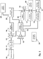
- Fig. 1 there is shown an ultrasound transducer 10 coupled to transmit / receive switch circuit 11.
- transmit / receive circuit 11 is shown without control connections to either signal processor 15 or system controller 22, though such control connections may be incorporated in other embodiments.
- a signal generator 14 is connected to transmit amplifier 12.
- transmit amplifier 12 is shown as a variable gain amplifier with the gain being controlled by signal processor 15, though in other embodiments amplifier 12 may be a fixed gain amplifier, or may be controlled by system controller 22.
- the transmit amplifier 12 is connected to the transmit port of the transmit / receive switch circuit 11.
- the receive port of the transmit / receive switch circuit 11 is connected to receive amplifier 13 which Is connected to signal processor 15.
- receive amplifier 13 is shown as a variable gain amplifier with the gain being controlled by signal processor 15, though in other embodiments amplifier 13 may be a fixed gain amplifier, or may be controlled by system controller 22.
- Signal processor 15 is connected to audio processor 16, display processor 17, and tactile processor 18, all of which are intended to drive elements of a user interface providing information to a user.
- Audio processor 16 is connected to audio transducer 19 which can produce audible information.
- Display processor 17 is connected to visual display 20, which can produce visual information.
- Tactile processor 18 is connected to tactile mechanism 21, which can produce information that can be sensed by touch.
- audio transducer 19 is a piezoelectric transducer. In another embodiment, audio transducer 19 may be an electromagnetic speaker. It will be appreciated that many different audio transducer technologies may be utilized to fulfill the intent of the present invention.
- visual display 20 is made up of one or more light emitting diodes (LEDs).
- LEDs light emitting diodes
- a single LED may be used to indicate the presence or absence of fluid and / or distance to the fluid, to the user through modulation of the brightness of the emitted light.
- two or more LEDs may be used to indicate the presence or absence of fluid to the user through modulation of the combined color of the light emitted by the LEDs.
- two or more LEDs may be used as an indicator of fluid through modulation of both brightness and color.
- many LEDs may be arranged so that an image may be formed which conveys information regarding the presence or absence of fluid. In such an embodiment, the image may be textual, graphical, or both.
- visual display 20 is made up of one or more liquid crystal displays. It will be appreciated that many different display technologies may be utilized to fulfill the intent of the present invention.
- tactile mechanism 21 is an electromechanical vibration device, such as an asymmetrical weight attached to an electric motor.
- the speed of the vibration may be used to indicate the presence or absence of fluid and / or distance to the fluid.
- the intensity of the vibration may be used as an indicator.
- the speed or intensity of vibration may be varied over time as an indicator.
- the presence or absence of vibration indicates the presence or absence of fluid in front of the ultrasound transducer, while the time between short bursts of vibration indicates distance to the fluid from the ultrasound transducer face.
- a solenoid may be used to move a mechanism to provide tactile feedback. It will be appreciated that many different tactile feedback technologies, including haptic technologies, may be utilized to fulfill the intent of the present invention.
- Audio processor 16 display processor 17, tactile processor 18, visual display 20 and tactile mechanism 21 are shown as connected to system controller 22. In any particular embodiment of the present invention, these connections may or may not be required.
- User inputs 25 provide means for the user to enable, disable, configure, or provide other input to the system.
- user inputs 25 incorporate electromechanical switches.
- user inputs 25 may incorporate potentiometers, rotary encoders, or proximity sensors. It will be appreciated that many different input technologies may be utilized to fulfill the intent of the present invention.
- Power source 24 supplies power to elements which require it.
- the power source is preferably a rechargeable battery, though it may be a non-rechargeable battery, another electrical storage device such as a capacitor, or a power supply drawing energy from mains or an electrical energy generation apparatus.
- system controller 22 triggers signal generator 14 to produce an electrical waveform that is amplified by transmit amplifier 12, passes through transmit / receive switch circuit 11, and excites transducer 10 so that it vibrates and produces acoustic waves that travel through tissue that is in contact with the transducer. Transmit / receive switch circuit 11 substantially blocks the amplified transmit signal from entering receive amplifier 13.
- the transmit / receive switch circuit may be a diode-based directional circuit which is well understood and has been used in diagnostic ultrasound systems for many years.
- the switch circuit may be a solid-state switch which is controlled by either the system controller 22 or the signal processor 15.
- the frequency of the acoustic waves produced in the system may vary greatly, but will preferably be in the range of 1 to 20 MHz.
- the number of wave cycles transmitted in a pulse may also vary greatly, but will preferably be in the range of 1 to 20 cycles.
- the pulse repetition frequency of the system may also vary greatly, but will preferably be in the range of 1 to 20000 Hz.
- Echoes returning to the transducer 10 from the tissue coupled to the transducer are converted to an electrical waveform by the transducer 10 and passed through the transmit / receive switch circuit 11 to the receive amplifier 13.
- the amplified signal is then passed to signal processor 15 to be analyzed.
- signal processor 15 is a digital signal processor, incorporating an analog to digital converter so that the output of the receive amplifier 13 may be converted to digital form.
- signal processor 15 is an analog signal processor, which may be as simple as a threshold detector that determines whether or not the amplitude of the received signal has exceeded a predetermined or adaptive limit.
- signal processor 15 controls the gain of the receive amplifier 13 in order to implement time-gain compensation (TGC).
- TGC is a well understood concept that has been incorporated in diagnostic ultrasound systems for many years, where gain is increased over time to compensate for the loss of energy in acoustic waves as they travel longer distances through tissue or fluid.
- the signal processor 15 is responsible for analyzing the signal representing returning echoes primarily to determine whether a fluid filled space is present in front of the transducer 10, and if so, to convert this information to a form more suitable for feedback to the user.
- Fig. 1 a illustrates the time-amplitude properties of a typical signal indicating the presence of a fluid-filled space. It will be appreciated that in such an illustration, time also represents distance traveled by an acoustic wave. An assumption is generally made for the speed of sound in tissue, which is about 1540 meters per second.
- the signal begins at point 155, which corresponds to the time when the system excites the ultrasound transducer to create the acoustic waves that will be used to search for a fluid filled space.
- a strong initial signal 150 may be present due to effects such as ring-down of the transducer. This initial signal is not relevant to fluid detection and should be minimized.
- the next portion of the signal 151 represents low level echoes from features within the tissue.
- Echo feature 152 is a higher amplitude feature representing the transition from tissue to fluid, while the next portion of the signal 153 is essentially echo free and represents the fluid.
- Echo feature 154 is a higher amplitude feature representing the transition from fluid to tissue, while the next portion of the signal 155 represents additional echoes from tissue features beyond the fluid compartment.
- the combination of features 152, 153, and 154 form the signature of a fluid filled space, that is, an initial echo feature indicating transition from tissue to fluid followed by a relatively echo free region, followed by a trailing echo feature indicating transition from fluid to tissue.
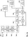
- Fig. 1b illustrates such an algorithm.
- the algorithm is implemented by first setting a binary detection signal 166 to its inactive state, and then performing envelope detection 160 on the echo signal to yield a relatively smoothed version of the returning echo signal.
- a filtering operation may be added before or after envelope detection in order to improve the signal's suitability for analysis.
- a band limiting filter 161 is provided before the envelope detection, and a transient filter 162 followed by a smoothing filter 163 is provided after envelope detection. It will be appreciated that such filters may implement many different types of processing.
- Processing block 164 attempts to identify an initial signal feature corresponding to signal feature 152 by examining portions of the echo signal in sequence from its beginning until a feature is found with amplitude significantly greater than its surrounding regions, and with duration consistent with a tissue to fluid interface. In one embodiment, such a feature is considered to be found if its amplitude exceeds twice the amplitude of the surrounding signal regions, and its duration exceeds the pulse length of the ultrasound signal used to interrogate the tissue and fluid. If this signal feature is found, processing block 165 attempts to identify a subsequent signal feature corresponding to feature 154 by examining further portions of the echo signal in sequence until a feature is found with amplitude significantly greater than its surrounding regions, and with duration consistent with a tissue to fluid interface. If this pattern of signal features is found, a fluid filled space is considered to have been found and a binary detection signal 166 is turned to its active state.
- a fluid filled space If a fluid filled space is detected, its approximate distance from the face of the ultrasound transducer and its approximate extent in the direction of the ultrasound beam is easily determined by computing the time intervals between the initial ultrasound pulse and the returning echoes from signal features corresponding to features 152 and 154 in Fig. 1a .
- the time points representing features 152 and 154 are preferably the midpoint of their extent in time, but may also be chosen to be anywhere within, immediately before, or immediately after their extent in time. Once these three time points are determined, the current position of the ultrasound transducer being used to guide the medical device relative to the fluid filled space may be determined and used to provide feedback to a user. Processing blocks 164 and 165 determine these two time points, store them, and make them available for subsequent processing through outputs 168 and 169.
- the outputs 168 and 169 may represent time in any suitable scale, for example, samples in a digital system, or as a number representing microseconds.
- the algorithm illustrated in Fig. 1b thus provides an indication as to whether or not a fluid filled space is present in front of the ultrasound transducer, and if so, at what depth in front of the transducer the leading and trailing edge of this space lies.
- Detection of a fluid-filled space can happen within tens of microseconds. If we assume that ultrasound travels through tissue at 1540 meters per second, or approximately 1.54 millimeters per microsecond, then a fluid filled space 4cm from the ultrasound transducer would give an initial echo corresponding to feature 152 in Fig. 1a in about 52 microseconds. In a case where the extent of the fluid filled space in the direction of the ultrasound beam is about 1cm, the echo corresponding to feature 154 in Fig. 1a would arrive about 12 microseconds later, depending on the speed of sound in the fluid. Events occurring in such short timeframes are generally not perceptible by human, so some mechanism must be employed to spread their presentation out over time, space, or both so as to make them perceptible.
- a simple example of this is the oscilloscope, which measures an electrical waveform that may have megahertz or gigahertz bandwidth, but then allows the user to examine details of the signal on a display where microseconds or nanoseconds of signal information are spread out over a display and held for a time so that the signal information is perceptible.
- Oscilloscopes were used in early diagnostic ultrasound systems, and in fact could be used to produce displays similar to that shown in Fig. 1a .
- Ultrasound imaging systems generally encode signal amplitude as brightness and time as distance in a display. A series of echo signals are processed and accumulated to produce a single image.
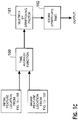
- Fig. 1c illustrates an algorithm for performing the above described time stretching operation utilizing the outputs of the algorithm of Fig. 1b .
- processing block 180 computes a time point corresponding to the distance half way between the leading edge of the fluid filled space and the trailing edge of the fluid filled space using outputs 168 and 169. This represents the approximate time that it would take an acoustic wave to travel from the transducer to the middle of the fluid filled space and back to the transducer.
- Multiplier 181 then multiplies this time by a stretching factor that will make this time perceptible to a human. In a preferred implementation, this stretching factor is chosen to be about 20000, so that a time of 50 microseconds is stretched out to one second.
- Output 182 represents this "stretched" time.
- audio processor 16 generates an electrical signal representing a short audible tone or "beep" which repeats at the temporal rate indicated by output 182 if output 166 is active, otherwise no signal is generated. This electrical signal is then used to generate a series of audible beeps through audio transducer 19.
- display processor 17 generates an electrical signal suitable for driving a LED so that it flashes at the temporal rate indicated by output 182 if output 166 is active, otherwise no signal is generated.
- actuator processor 18 uses this electrical signal to drive visual display 20, which in this case is simply a LED, so that it flashes as described above.
- actuator processor 18 generates an electrical signal suitable for driving a solenoid with a spring-return plunger of sufficient mass so that its motion is perceptible by touch in a pulsed fashion at a temporal rate indicated by output 182 if output 166 is active, otherwise no signal is generated.
- This electrical signal is then used to drive tactile mechanism 21, which in this case is simply the solenoid described above.
- audio transducer 19 will beep at 1Hz
- visual display 20 will flash at 1Hz
- tactile mechanism 21 will make a physical movement perceptible by touch at 1Hz.
- the rate of audio, visual, and tactile feedback will increase.
- any of the audio, visual, or tactile feedback mechanisms may be enabled or disabled in any combination by the system controller 22. It will also be appreciated that, in any particular implementation, mechanisms for audio, visual, or tactile feedback may or may not be present, so long as at least one such feedback mechanism is present. It will also be appreciated that, in any particular implementation, mechanisms for audio, visual, or tactile feedback may be used to provide different types of feedback at the same time.
- visual display 20 may display a red light if a fluid filled space is not detected and a green light if such a space is detected, while audio processor and transducer 16 and 19 provide a series of beeps indicating distance to the fluid filled space if such a space is detected, and tactile mechanism 21 provides feedback through physical motion when the ultrasound transducer is determined to be in the fluid filled space. It will be apparent that the mechanisms for audio, visual, and tactile feedback may be used many such combinations to provide feedback to the user.
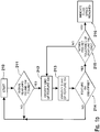
- Fig. 1d features corresponding to the signal features identified in Fig. 1a are referenced.
- the algorithm is initialized in box 210, which clears any indication that a fluid filled space has been reached and clears any stored location in processing block 213.
- Decision block 211 indicates whether signal features 152 and 154 of Fig. 1a have been found as described herein, indicating the presence of a fluid filled space. If these signal features have not been found, the algorithm returns to its initialization state 210. If the signal features have been found, processing block 212 determines the end of signal feature 150. In an embodiment, this determination may be made by a threshold test after block 163 of Fig. 1b .
- Processing block 213 determines the beginning of signal feature 154.
- this determination may be made by a threshold test as may be performed in block 164 of Fig. 1b .
- Processing block 213 then compares the location of signal feature 154 to any previously stored location. If the current location is within a pre-determined distance from the previously stored location, tracking is considered successful and feature 154 is indicated to have been identified. If the stored location information is cleared, as would be the case in the first iteration through the algorithm, feature 154 would also be indicated as having been found. If the location of signal feature 154 is outside of the pre-determined distance from the previously stored location, tracking is considered unsuccessful, and feature 154 is indicated as not having been identified. Decision block 214 determines whether or not the start of signal feature 154 has been found in processing block 213.
- decision block 215 determines whether the beginning of signal feature 154 is within a pre-set tolerance of the end of signal feature 150. If it is, an indication is given to the user that the fluid-filled space has been reached. If not, the algorithm returns to processing block 154.
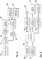
- Fig. 2 is a block diagram of a portion of the system illustrated in Fig. 1 , but with a wireless transmitter 36 and receiver 37 added.
- Fig. 3 shows the remainder of the elements of Fig. 1 that are missing from Fig. 2 , with the addition of wireless receiver 50 and transmitter 51.
- the combination of the systems illustrated in Fig. 2 and Fig. 3 thus, in combination, may implement all of the functions discussed above for the system illustrated in Fig. 1 by sending appropriate data across a wireless link formed with the wireless transmitters and receivers.
- the wireless link is formed with low-power BluetoothTM components, though it will be appreciated that many different forms of communication, including RF, optical, and ultrasonic means, may be used to form this link.
- the band limiting filter function may be implemented in signal processor 35 of Fig. 2
- an additional signal processor added to the system illustrated in Fig. 3 may implement detection and smoothing operations.
- Fig. 4 illustrates a physical implementation of the system illustrated in Fig. 1 .
- Hollow member, or "stylet" 71 with an ultrasound transducer corresponding to transducer 10 of Fig. 1 positioned at its distal end is shown inside a cut-away view of drainage catheter 70.
- the drainage catheter will incorporate at least one drainage port in the side of the catheter near its distal end, but such ports are not shown in the illustration.
- the tip of drainage catheter 70 incorporates a "fishmouth" slit 72 that allows stylet 71 to be pushed through the otherwise closed end of the catheter 70 as is described further below.
- Stylet 71 which is preferably constructed of an electrically conductive material and coupled to the face of the ultrasound transducer, also contains a wire connected to the rear of the ultrasound transducer, which in combination with the conductive stylet form an electrical circuit corresponding to connection 23 in Fig. 1 .
- Stylet 71 is mechanically coupled to housing 73, which contains electronics and a power source corresponding to the other elements in Fig. 1 .
- the power source is preferably a battery power source, though it may be another electrical storage device such as a capacitor, or a power supply drawing energy from mains or an electrical energy generation apparatus.
- Graphical display 76 and LED lamps 75 are shown, both corresponding to visual display 20 of Fig. 1 , as are user inputs 74 corresponding to user inputs 25 of Fig. 1 .
- Fig. 5 illustrates a similar embodiment to that of Fig. 4 , where now the stylet 81 corresponding to stylet 71 of Fig. 4 is connected by a small co-axial cable 82 to housing 83 which contains the electronics and power source.
- the power source is preferably a rechargeable battery, though it may be a non-rechargeable battery, another electrical storage device such as a capacitor, or a power supply drawing energy from mains or an electrical energy generation apparatus.
- the proximal end of the catheter 80 corresponding to the catheter 70 of Fig. 4 is shown, as are the graphical display 86 and LED lamps 85 corresponding to elements 76 and 75, respectively, of Fig. 4 .
- User inputs 84 corresponding to user inputs 74 of Fig. 4 are also shown.
- Fig. 5a illustrates a similar embodiment to that of Fig. 4 , where now the stylet 201 corresponding to stylet 71 of Fig. 4 is mechanically coupled to housing 202 containing electronics, which is in turn connected by cable 203 to housing 204 which contains electronics.
- housing 202 may actually be the same as hollow stylet 201.
- electrical tuning components such as one or more inductors or capacitors may be incorporated in close physical proximity to the transducer at the distal end of hollow stylet 201.
- a power source may be incorporated in housing 202, housing 204, or in both.
- a power source is incorporated in housing 204, and any power required by electronics contained in housing 202 is supplied through cable 203.
- the power source is preferably a rechargeable battery, though it may be a non-rechargeable battery, another electrical storage device such as a capacitor, or a power supply drawing energy from mains or an electrical energy generation apparatus.
- the proximal end of the catheter 200 corresponding to the catheter 70 of Fig. 4 is shown, as are the graphical display 205 and LED lamps 206 corresponding to elements 76 and 75, respectively, of Fig. 4 .
- User inputs 207 corresponding to user inputs 74 of Fig. 4 are also shown.
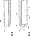
- Figures 6 and 7 further illustrate the configuration of the catheter that allows the distal end of the stylet to be pushed through its end.
- stylet 91 incorporating the ultrasound transducer at its distal end is shown inside a cut-away view of a drainage catheter.
- the drainage catheter will incorporate at least one drainage port in the side of the catheter near its distal end, but such ports are not shown in the illustration.
- a slit 92 is cut in the distal end of the catheter so that an opening may be created.
- the stylet 101 is now shown pushed through the slit at the distal end of the catheter 100.
- stylet 122 incorporates a feature 123 so that its lateral dimension, or most commonly its diameter, is reduced near its distal end. This feature fits against a corresponding "lip" feature in the distal end of the catheter 120 so that the distal end of the stylet incorporating the ultrasound transducer 124 is exposed, but force may be applied to the catheter through the stylet.
- the distal end of the catheter 120 is made from a material that is more rigid than the material of the body of the catheter 121.
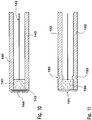
- Fig. 11 illustrates a construction detail of an embodiment of the ultrasound transducer 141 corresponding to transducer 10 of Fig. 1 inside the stylet 140 corresponding to stylet 71 of Fig. 4 .
- the ultrasound transducer is most preferably constructed of a piezo-electric ceramic material, and is plated with a conductive metal, preferably silver or gold, on its front and back face.
- a wire 142 is bonded to the plated back face of the transducer, and the transducer is bonded inside the hollow stylet 140 with a glue.
- the plating on the back face of the transducer is configured so that it does not reach the edge of the transducer, so that it is not in electrical contact with the stylet.
- a small piece of conductive material 143 is bonded to the face of the transducer 141 and to the distal end of the stylet 140 so that the front face of the transducer is in electrical contact with the stylet.
- An acoustically transmissive protective coating 144 which is preferably a latex or epoxy, is deposited at the tip of the stylet. It will be apparent that the conductive material 143 is not required if the plating of the front face of the transducer wraps around the edge of the transducer so that it is in electrical contact with the stylet.
- the ultrasound transducer 140 may be grounded through the conductive stylet 140, and transmit and receive signals may be conveyed through wire 142.
- Fig. 12 also illustrates a construction detail of an embodiment of the ultrasound transducer 190 corresponding to transducer 10 of Fig. 1 inside the stylet 192 corresponding to stylet 71 of Fig. 4 .
- the plating on the front of the transducer wraps around the side of the transducer so that the additional conductive element is not required between the face of the transducer and protective layer 191.
- An additional feature 193 is added to the hollow stylet which is a narrowing of the stylet near its distal end that acts as a back-stop for the transducer 190 to aid in positioning during manufacturing.
Landscapes
- Health & Medical Sciences (AREA)
- Life Sciences & Earth Sciences (AREA)
- Engineering & Computer Science (AREA)
- Biomedical Technology (AREA)
- Public Health (AREA)
- Animal Behavior & Ethology (AREA)
- Heart & Thoracic Surgery (AREA)
- Veterinary Medicine (AREA)
- General Health & Medical Sciences (AREA)
- Surgery (AREA)
- Medical Informatics (AREA)
- Molecular Biology (AREA)
- Nuclear Medicine, Radiotherapy & Molecular Imaging (AREA)
- Biophysics (AREA)
- Anesthesiology (AREA)
- Hematology (AREA)
- Pathology (AREA)
- Radiology & Medical Imaging (AREA)
- Physics & Mathematics (AREA)
- Ophthalmology & Optometry (AREA)
- Pulmonology (AREA)
- Otolaryngology (AREA)
- Neurology (AREA)
- Robotics (AREA)
- Vascular Medicine (AREA)
- Ultra Sonic Daignosis Equipment (AREA)
- External Artificial Organs (AREA)
Claims (16)
- Chirurgische Vorrichtung, welche aufweist:Eine Sonde mit einem proximalen Ende und einem distalen Ende und mit einer Längsbohrung hierdurch,einen Ultraschallwandler, welcher an dem distalen Ende der Längsbohrung der Sonde angeordnet ist, undeiner Elektronikschaltung, welche an den Ultraschallwandler gekoppelt ist,wobei die Elektronikschaltung dafür konfiguriert ist, eine Signalverarbeitung umzusetzen, welche einen mit Flüssigkeit gefüllten Raum vor dem Ultraschallwandler erkennt,dadurch gekennzeichnet, dassdie Elektronikschaltung weiterhin dafür konfiguriert ist, eine Zeit-Dehn-Technik umzusetzen, welche Informationen von aus zu dem Ultraschallwandler zurückkehrenden Echos zur Präsentation an einen Nutzer formatiert.
- Vorrichtung nach Anspruch 1, welche weiterhin eine optische Anzeige aufweist.
- Vorrichtung nach Anspruch 1, wobei mindestens ein Teil der Elektronikschaltung innerhalb der Längsbohrung der Sonde angeordnet ist.
- Vorrichtung nach Anspruch 1, wobei mindestens ein Teil der Elektronikschaltung in einem Gehäuse angeordnet ist, welches über ein flexibles Kabel vernetzbar mit dem Ultraschallwandler verknüpft ist.
- Vorrichtung nach Anspruch 1, wobei die Elektronikschaltung in zwei Teilen umgesetzt ist, welche durch ein flexibles Kabel vernetzbar verknüpft sind.
- Vorrichtung nach Anspruch 1, wobei ein erster Teil der Elektronikschaltung innerhalb eines ersten Gehäuses angeordnet ist, welches mechanisch mit der Sonde gekoppelt ist, und ein zweiter Teil der Elektronikschaltung innerhalb eines zweiten Gehäuses angeordnet ist und mit dem ersten Teil über ein flexibles Kabel vernetzbar verknüpft ist.
- Vorrichtung nach Anspruch 1, wobei ein erster Teil der Elektronikschaltung innerhalb eines ersten Gehäuses angeordnet ist, welches mechanisch mit der Sonde gekoppelt ist, und ein zweiter Teil der Elektronikschaltung innerhalb eines zweiten Gehäuses angeordnet ist und mit dem ersten Teil über eine kabellose Schnittstelle verbunden ist.
- Vorrichtung nach Anspruch 1, wobei eine optische Anzeige innerhalb eines Gehäuses angeordnet ist, welches mechanisch mit der Sonde gekoppelt ist.
- Vorrichtung nach Anspruch 4, wobei die Sonde und das Kabel als Einwegteile ausgestaltet sind, und die Elektronikschaltung und das Gehäuse als Mehrwegteile ausgestaltet sind.
- Vorrichtung nach Anspruch 1, welche weiterhin einen Katheter aufweist, welcher ein proximales Ende und ein distales Ende mit einer Längsbohrung hierdurch aufweist, und wobei die Sonde so dimensioniert und dafür ausgelegt ist, dass sie gezielt in der Längsbohrung des Katheters angeordnet werden kann.
- Vorrichtung nach Anspruch 1, wobei der Ultraschallwandler innerhalb der Längsbohrung der Sonde angeordnet ist.
- Vorrichtung nach Anspruch 1, wobei der Ultraschallwandler außerhalb der Längsbohrung der Sonde angeordnet ist.
- Vorrichtung nach Anspruch 10, wobei der Katheter eine innere Lippe beinhaltet, gegen welche mindestens ein Teil der Sonde gedrückt wird.
- Vorrichtung nach Anspruch 10, wobei der Katheter ein offenes distales Ende aufnimmt.
- Vorrichtung nach Anspruch 10, wobei der Katheter mindestens eine Auslassöffnung in einer Seite des Katheters aufnimmt.
- Vorrichtung nach Anspruch 1, wobei die Sonde aus einem elektrisch leitfähigen Material besteht, und dazu verwendet wird, einen Teil einer elektrischen Verbindung zu dem Ultraschallwandler zu bilden.
Applications Claiming Priority (2)
| Application Number | Priority Date | Filing Date | Title |
|---|---|---|---|
| US201361830758P | 2013-06-04 | 2013-06-04 | |
| PCT/US2014/040143 WO2014197295A2 (en) | 2013-06-04 | 2014-05-30 | Method and apparatus for positioning medical device |
Publications (3)
| Publication Number | Publication Date |
|---|---|
| EP3003160A2 EP3003160A2 (de) | 2016-04-13 |
| EP3003160A4 EP3003160A4 (de) | 2017-02-08 |
| EP3003160B1 true EP3003160B1 (de) | 2018-04-18 |
Family
ID=51985895
Family Applications (1)
| Application Number | Title | Priority Date | Filing Date |
|---|---|---|---|
| EP14807393.5A Not-in-force EP3003160B1 (de) | 2013-06-04 | 2014-05-30 | Vorrichtung zur positionierung einer medizinischen vorrichtung |
Country Status (4)
| Country | Link |
|---|---|
| US (2) | US20140358007A1 (de) |
| EP (1) | EP3003160B1 (de) |
| JP (1) | JP6404334B2 (de) |
| WO (1) | WO2014197295A2 (de) |
Cited By (1)
| Publication number | Priority date | Publication date | Assignee | Title |
|---|---|---|---|---|
| FR3113233A1 (fr) | 2020-08-06 | 2022-02-11 | Marc LENFANT | Complexe sonde de derivation ventriculaire externe et stylet echographique pour une pose sous guidage par imagerie continue |
Families Citing this family (5)
| Publication number | Priority date | Publication date | Assignee | Title |
|---|---|---|---|---|
| US20160331927A1 (en) * | 2014-01-31 | 2016-11-17 | The Regents Of The University Of Colorado, A Body Corporate | Ventricular Catheter |
| US11051761B2 (en) * | 2015-06-15 | 2021-07-06 | Sunnybrook Research Institute | Intravascular imaging catheters and methods of use thereof |
| CN105426024B (zh) * | 2015-11-25 | 2018-03-27 | 吉林大学 | 一种基于超声波聚焦的触觉反馈系统及方法 |
| WO2018108638A1 (en) * | 2016-12-12 | 2018-06-21 | Koninklijke Philips N.V. | Smart tracked interventional tools including wireless transceiver |
| CN120302927A (zh) * | 2022-10-28 | 2025-07-11 | 瑞维佳神经成像有限公司 | 用于放置在脑室系统中的导管 |
Family Cites Families (15)
| Publication number | Priority date | Publication date | Assignee | Title |
|---|---|---|---|---|
| JPS4830874B1 (de) * | 1967-05-29 | 1973-09-25 | ||
| US5158088A (en) * | 1990-11-14 | 1992-10-27 | Advanced Technology Laboratories, Inc. | Ultrasonic diagnostic systems for imaging medical instruments within the body |
| US5156157A (en) * | 1991-03-08 | 1992-10-20 | Telectronics Pacing Systems, Inc. | Catheter-mounted doppler ultrasound transducer and signal processor |
| US5150714A (en) * | 1991-05-10 | 1992-09-29 | Sri International | Ultrasonic inspection method and apparatus with audible output |
| US5690117A (en) * | 1995-03-20 | 1997-11-25 | Gilbert; John W. | Ultrasonic-fiberoptic imaging ventricular catheter |
| US6870792B2 (en) * | 2000-04-04 | 2005-03-22 | Irobot Corporation | Sonar Scanner |
| DE60134739D1 (de) * | 2000-05-16 | 2008-08-21 | Atrionix Inc | Katheter mit lenkbarer spitze und spurausrichtungsmechanismus eines führungsdrahts |
| US20040267121A1 (en) * | 2003-06-12 | 2004-12-30 | Sarvazyan Armen P. | Device and method for biopsy guidance using a tactile breast imager |
| US8000771B2 (en) * | 2003-09-02 | 2011-08-16 | Cardiac Pacemakers, Inc. | Method and apparatus for catheterization by detecting signals indicating proximity to anatomical features |
| US20070083100A1 (en) * | 2005-07-20 | 2007-04-12 | Sebastian Schulz-Stubner | Ventriculostomy Catheter with In Situ Ultrasound Capability |
| IL191443A0 (en) * | 2007-05-14 | 2008-12-29 | Arnon Agmon | A guide for placement of catheter into brain and a method of utilizing the same |
| US9521961B2 (en) * | 2007-11-26 | 2016-12-20 | C. R. Bard, Inc. | Systems and methods for guiding a medical instrument |
| US20100256483A1 (en) * | 2009-04-03 | 2010-10-07 | Insite Medical Technologies, Inc. | Devices and methods for tissue navigation |
| US20120010506A1 (en) * | 2010-07-08 | 2012-01-12 | Immersion Corporation | Multimodal laparoscopic ultrasound device with feedback system |
| CN104114104B (zh) * | 2011-12-08 | 2016-12-07 | 华盛顿大学商业中心 | 超声探针 |
-
2014
- 2014-05-30 WO PCT/US2014/040143 patent/WO2014197295A2/en not_active Ceased
- 2014-05-30 EP EP14807393.5A patent/EP3003160B1/de not_active Not-in-force
- 2014-05-30 US US14/291,074 patent/US20140358007A1/en not_active Abandoned
- 2014-05-30 JP JP2016518354A patent/JP6404334B2/ja not_active Expired - Fee Related
-
2018
- 2018-12-10 US US16/214,500 patent/US20190105014A1/en not_active Abandoned
Non-Patent Citations (1)
| Title |
|---|
| None * |
Cited By (1)
| Publication number | Priority date | Publication date | Assignee | Title |
|---|---|---|---|---|
| FR3113233A1 (fr) | 2020-08-06 | 2022-02-11 | Marc LENFANT | Complexe sonde de derivation ventriculaire externe et stylet echographique pour une pose sous guidage par imagerie continue |
Also Published As
| Publication number | Publication date |
|---|---|
| US20190105014A1 (en) | 2019-04-11 |
| EP3003160A4 (de) | 2017-02-08 |
| JP6404334B2 (ja) | 2018-10-10 |
| US20140358007A1 (en) | 2014-12-04 |
| WO2014197295A3 (en) | 2015-02-26 |
| JP2016525918A (ja) | 2016-09-01 |
| EP3003160A2 (de) | 2016-04-13 |
| WO2014197295A2 (en) | 2014-12-11 |
Similar Documents
| Publication | Publication Date | Title |
|---|---|---|
| US20190105014A1 (en) | Method and apparatus for positioning medical device | |
| US5242386A (en) | Echographic suction cannula | |
| EP3531921B1 (de) | Ultraschallsystem mit gewebeanalysator | |
| US5795298A (en) | System for sharing electrocardiogram electrodes and transducers | |
| JPH0643242A (ja) | 超音波イメージ化システム | |
| JP6450328B2 (ja) | 超音波を用いる低侵襲デバイスの能動的位置特定及び視覚化 | |
| JP3482434B2 (ja) | 超音波アセンブリ | |
| US20150342618A1 (en) | Ultrasound bone cutting surgical probe with dynamic tissue characterization | |
| CN101460094A (zh) | 多频多普勒超声波探头 | |
| US11045167B2 (en) | Forward-looking ultrasound array probe for intravascular imaging and navigation applications | |
| US20220395255A1 (en) | Transducer for ultrasound measuring systems and methods | |
| WO2007047993A2 (en) | System and methods for sealing a vascular opening | |
| US20060106315A1 (en) | Guided hypodermic cannula | |
| US20220330918A1 (en) | Ultrasound marker, ultrasound marker system and method of operating an ultrasound marker system | |
| US12611175B2 (en) | Ultrasound diagnostic apparatus | |
| CN113117264A (zh) | 聚焦超声装置及聚焦超声换能器聚焦方法 | |
| US11872413B2 (en) | Control method for the treatment of brain tissue using an ultrasonic probe and an implanted acoustic window on the cranium | |
| CN105792755B (zh) | 超声波探头及使用该超声波探头的活体血管直径的测量方法 | |
| US20230028061A1 (en) | Needle localization reflectors, systems, and methods | |
| US20250359845A1 (en) | Ultrasound measuring pulser receiver systems and methods | |
| EP3949864B1 (de) | Ultraschallsonde und ultraschallbildgebungsvorrichtung damit | |
| CN110786931B (zh) | 对超声影像增强显示的装置和方法 | |
| EP4262567B1 (de) | System und verfahren zur bestimmung von positionsinformationen |
Legal Events
| Date | Code | Title | Description |
|---|---|---|---|
| PUAI | Public reference made under article 153(3) epc to a published international application that has entered the european phase |
Free format text: ORIGINAL CODE: 0009012 |
|
| 17P | Request for examination filed |
Effective date: 20151223 |
|
| AK | Designated contracting states |
Kind code of ref document: A2 Designated state(s): AL AT BE BG CH CY CZ DE DK EE ES FI FR GB GR HR HU IE IS IT LI LT LU LV MC MK MT NL NO PL PT RO RS SE SI SK SM TR |
|
| AX | Request for extension of the european patent |
Extension state: BA ME |
|
| DAX | Request for extension of the european patent (deleted) | ||
| REG | Reference to a national code |
Ref country code: DE Ref legal event code: R079 Ref document number: 602014024195 Country of ref document: DE Free format text: PREVIOUS MAIN CLASS: A61B0008120000 Ipc: A61M0025010000 |
|
| A4 | Supplementary search report drawn up and despatched |
Effective date: 20170110 |
|
| RIC1 | Information provided on ipc code assigned before grant |
Ipc: A61M 25/00 20060101ALI20170103BHEP Ipc: A61B 8/08 20060101ALI20170103BHEP Ipc: A61B 34/20 20160101ALI20170103BHEP Ipc: A61B 8/00 20060101ALI20170103BHEP Ipc: A61M 25/01 20060101AFI20170103BHEP Ipc: A61M 27/00 20060101ALI20170103BHEP Ipc: A61B 10/00 20060101ALI20170103BHEP |
|
| GRAP | Despatch of communication of intention to grant a patent |
Free format text: ORIGINAL CODE: EPIDOSNIGR1 |
|
| INTG | Intention to grant announced |
Effective date: 20171117 |
|
| GRAS | Grant fee paid |
Free format text: ORIGINAL CODE: EPIDOSNIGR3 |
|
| GRAA | (expected) grant |
Free format text: ORIGINAL CODE: 0009210 |
|
| AK | Designated contracting states |
Kind code of ref document: B1 Designated state(s): AL AT BE BG CH CY CZ DE DK EE ES FI FR GB GR HR HU IE IS IT LI LT LU LV MC MK MT NL NO PL PT RO RS SE SI SK SM TR |
|
| REG | Reference to a national code |
Ref country code: GB Ref legal event code: FG4D |
|
| REG | Reference to a national code |
Ref country code: CH Ref legal event code: EP |
|
| REG | Reference to a national code |
Ref country code: AT Ref legal event code: REF Ref document number: 989791 Country of ref document: AT Kind code of ref document: T Effective date: 20180515 |
|
| REG | Reference to a national code |
Ref country code: IE Ref legal event code: FG4D |
|
| REG | Reference to a national code |
Ref country code: DE Ref legal event code: R096 Ref document number: 602014024195 Country of ref document: DE |
|
| REG | Reference to a national code |
Ref country code: FR Ref legal event code: PLFP Year of fee payment: 5 |
|
| REG | Reference to a national code |
Ref country code: NL Ref legal event code: MP Effective date: 20180418 |
|
| REG | Reference to a national code |
Ref country code: LT Ref legal event code: MG4D |
|
| PG25 | Lapsed in a contracting state [announced via postgrant information from national office to epo] |
Ref country code: NL Free format text: LAPSE BECAUSE OF FAILURE TO SUBMIT A TRANSLATION OF THE DESCRIPTION OR TO PAY THE FEE WITHIN THE PRESCRIBED TIME-LIMIT Effective date: 20180418 |
|
| PG25 | Lapsed in a contracting state [announced via postgrant information from national office to epo] |
Ref country code: ES Free format text: LAPSE BECAUSE OF FAILURE TO SUBMIT A TRANSLATION OF THE DESCRIPTION OR TO PAY THE FEE WITHIN THE PRESCRIBED TIME-LIMIT Effective date: 20180418 Ref country code: AL Free format text: LAPSE BECAUSE OF FAILURE TO SUBMIT A TRANSLATION OF THE DESCRIPTION OR TO PAY THE FEE WITHIN THE PRESCRIBED TIME-LIMIT Effective date: 20180418 Ref country code: SE Free format text: LAPSE BECAUSE OF FAILURE TO SUBMIT A TRANSLATION OF THE DESCRIPTION OR TO PAY THE FEE WITHIN THE PRESCRIBED TIME-LIMIT Effective date: 20180418 Ref country code: LT Free format text: LAPSE BECAUSE OF FAILURE TO SUBMIT A TRANSLATION OF THE DESCRIPTION OR TO PAY THE FEE WITHIN THE PRESCRIBED TIME-LIMIT Effective date: 20180418 Ref country code: PL Free format text: LAPSE BECAUSE OF FAILURE TO SUBMIT A TRANSLATION OF THE DESCRIPTION OR TO PAY THE FEE WITHIN THE PRESCRIBED TIME-LIMIT Effective date: 20180418 Ref country code: BG Free format text: LAPSE BECAUSE OF FAILURE TO SUBMIT A TRANSLATION OF THE DESCRIPTION OR TO PAY THE FEE WITHIN THE PRESCRIBED TIME-LIMIT Effective date: 20180718 Ref country code: NO Free format text: LAPSE BECAUSE OF FAILURE TO SUBMIT A TRANSLATION OF THE DESCRIPTION OR TO PAY THE FEE WITHIN THE PRESCRIBED TIME-LIMIT Effective date: 20180718 Ref country code: FI Free format text: LAPSE BECAUSE OF FAILURE TO SUBMIT A TRANSLATION OF THE DESCRIPTION OR TO PAY THE FEE WITHIN THE PRESCRIBED TIME-LIMIT Effective date: 20180418 |
|
| PG25 | Lapsed in a contracting state [announced via postgrant information from national office to epo] |
Ref country code: LV Free format text: LAPSE BECAUSE OF FAILURE TO SUBMIT A TRANSLATION OF THE DESCRIPTION OR TO PAY THE FEE WITHIN THE PRESCRIBED TIME-LIMIT Effective date: 20180418 Ref country code: RS Free format text: LAPSE BECAUSE OF FAILURE TO SUBMIT A TRANSLATION OF THE DESCRIPTION OR TO PAY THE FEE WITHIN THE PRESCRIBED TIME-LIMIT Effective date: 20180418 Ref country code: HR Free format text: LAPSE BECAUSE OF FAILURE TO SUBMIT A TRANSLATION OF THE DESCRIPTION OR TO PAY THE FEE WITHIN THE PRESCRIBED TIME-LIMIT Effective date: 20180418 Ref country code: GR Free format text: LAPSE BECAUSE OF FAILURE TO SUBMIT A TRANSLATION OF THE DESCRIPTION OR TO PAY THE FEE WITHIN THE PRESCRIBED TIME-LIMIT Effective date: 20180719 |
|
| REG | Reference to a national code |
Ref country code: CH Ref legal event code: PL |
|
| REG | Reference to a national code |
Ref country code: AT Ref legal event code: MK05 Ref document number: 989791 Country of ref document: AT Kind code of ref document: T Effective date: 20180418 |
|
| PG25 | Lapsed in a contracting state [announced via postgrant information from national office to epo] |
Ref country code: PT Free format text: LAPSE BECAUSE OF FAILURE TO SUBMIT A TRANSLATION OF THE DESCRIPTION OR TO PAY THE FEE WITHIN THE PRESCRIBED TIME-LIMIT Effective date: 20180820 |
|
| REG | Reference to a national code |
Ref country code: DE Ref legal event code: R097 Ref document number: 602014024195 Country of ref document: DE |
|
| REG | Reference to a national code |
Ref country code: BE Ref legal event code: MM Effective date: 20180531 |
|
| PG25 | Lapsed in a contracting state [announced via postgrant information from national office to epo] |
Ref country code: MC Free format text: LAPSE BECAUSE OF FAILURE TO SUBMIT A TRANSLATION OF THE DESCRIPTION OR TO PAY THE FEE WITHIN THE PRESCRIBED TIME-LIMIT Effective date: 20180418 Ref country code: SK Free format text: LAPSE BECAUSE OF FAILURE TO SUBMIT A TRANSLATION OF THE DESCRIPTION OR TO PAY THE FEE WITHIN THE PRESCRIBED TIME-LIMIT Effective date: 20180418 Ref country code: DK Free format text: LAPSE BECAUSE OF FAILURE TO SUBMIT A TRANSLATION OF THE DESCRIPTION OR TO PAY THE FEE WITHIN THE PRESCRIBED TIME-LIMIT Effective date: 20180418 Ref country code: EE Free format text: LAPSE BECAUSE OF FAILURE TO SUBMIT A TRANSLATION OF THE DESCRIPTION OR TO PAY THE FEE WITHIN THE PRESCRIBED TIME-LIMIT Effective date: 20180418 Ref country code: AT Free format text: LAPSE BECAUSE OF FAILURE TO SUBMIT A TRANSLATION OF THE DESCRIPTION OR TO PAY THE FEE WITHIN THE PRESCRIBED TIME-LIMIT Effective date: 20180418 Ref country code: RO Free format text: LAPSE BECAUSE OF FAILURE TO SUBMIT A TRANSLATION OF THE DESCRIPTION OR TO PAY THE FEE WITHIN THE PRESCRIBED TIME-LIMIT Effective date: 20180418 Ref country code: CZ Free format text: LAPSE BECAUSE OF FAILURE TO SUBMIT A TRANSLATION OF THE DESCRIPTION OR TO PAY THE FEE WITHIN THE PRESCRIBED TIME-LIMIT Effective date: 20180418 |
|
| REG | Reference to a national code |
Ref country code: IE Ref legal event code: MM4A |
|
| PLBE | No opposition filed within time limit |
Free format text: ORIGINAL CODE: 0009261 |
|
| STAA | Information on the status of an ep patent application or granted ep patent |
Free format text: STATUS: NO OPPOSITION FILED WITHIN TIME LIMIT |
|
| PG25 | Lapsed in a contracting state [announced via postgrant information from national office to epo] |
Ref country code: IT Free format text: LAPSE BECAUSE OF FAILURE TO SUBMIT A TRANSLATION OF THE DESCRIPTION OR TO PAY THE FEE WITHIN THE PRESCRIBED TIME-LIMIT Effective date: 20180418 Ref country code: CH Free format text: LAPSE BECAUSE OF NON-PAYMENT OF DUE FEES Effective date: 20180531 Ref country code: LI Free format text: LAPSE BECAUSE OF NON-PAYMENT OF DUE FEES Effective date: 20180531 Ref country code: SM Free format text: LAPSE BECAUSE OF FAILURE TO SUBMIT A TRANSLATION OF THE DESCRIPTION OR TO PAY THE FEE WITHIN THE PRESCRIBED TIME-LIMIT Effective date: 20180418 |
|
| 26N | No opposition filed |
Effective date: 20190121 |
|
| PG25 | Lapsed in a contracting state [announced via postgrant information from national office to epo] |
Ref country code: LU Free format text: LAPSE BECAUSE OF NON-PAYMENT OF DUE FEES Effective date: 20180530 |
|
| PG25 | Lapsed in a contracting state [announced via postgrant information from national office to epo] |
Ref country code: IE Free format text: LAPSE BECAUSE OF NON-PAYMENT OF DUE FEES Effective date: 20180530 |
|
| PG25 | Lapsed in a contracting state [announced via postgrant information from national office to epo] |
Ref country code: BE Free format text: LAPSE BECAUSE OF NON-PAYMENT OF DUE FEES Effective date: 20180531 Ref country code: SI Free format text: LAPSE BECAUSE OF FAILURE TO SUBMIT A TRANSLATION OF THE DESCRIPTION OR TO PAY THE FEE WITHIN THE PRESCRIBED TIME-LIMIT Effective date: 20180418 |
|
| PG25 | Lapsed in a contracting state [announced via postgrant information from national office to epo] |
Ref country code: MT Free format text: LAPSE BECAUSE OF NON-PAYMENT OF DUE FEES Effective date: 20180530 |
|
| PG25 | Lapsed in a contracting state [announced via postgrant information from national office to epo] |
Ref country code: TR Free format text: LAPSE BECAUSE OF FAILURE TO SUBMIT A TRANSLATION OF THE DESCRIPTION OR TO PAY THE FEE WITHIN THE PRESCRIBED TIME-LIMIT Effective date: 20180418 |
|
| PG25 | Lapsed in a contracting state [announced via postgrant information from national office to epo] |
Ref country code: CY Free format text: LAPSE BECAUSE OF FAILURE TO SUBMIT A TRANSLATION OF THE DESCRIPTION OR TO PAY THE FEE WITHIN THE PRESCRIBED TIME-LIMIT Effective date: 20180418 Ref country code: HU Free format text: LAPSE BECAUSE OF FAILURE TO SUBMIT A TRANSLATION OF THE DESCRIPTION OR TO PAY THE FEE WITHIN THE PRESCRIBED TIME-LIMIT; INVALID AB INITIO Effective date: 20140530 Ref country code: MK Free format text: LAPSE BECAUSE OF NON-PAYMENT OF DUE FEES Effective date: 20180418 |
|
| PG25 | Lapsed in a contracting state [announced via postgrant information from national office to epo] |
Ref country code: IS Free format text: LAPSE BECAUSE OF FAILURE TO SUBMIT A TRANSLATION OF THE DESCRIPTION OR TO PAY THE FEE WITHIN THE PRESCRIBED TIME-LIMIT Effective date: 20180818 |
|
| PGFP | Annual fee paid to national office [announced via postgrant information from national office to epo] |
Ref country code: FR Payment date: 20200525 Year of fee payment: 7 Ref country code: DE Payment date: 20200528 Year of fee payment: 7 |
|
| PGFP | Annual fee paid to national office [announced via postgrant information from national office to epo] |
Ref country code: GB Payment date: 20200527 Year of fee payment: 7 |
|
| REG | Reference to a national code |
Ref country code: DE Ref legal event code: R119 Ref document number: 602014024195 Country of ref document: DE |
|
| GBPC | Gb: european patent ceased through non-payment of renewal fee |
Effective date: 20210530 |
|
| PG25 | Lapsed in a contracting state [announced via postgrant information from national office to epo] |
Ref country code: GB Free format text: LAPSE BECAUSE OF NON-PAYMENT OF DUE FEES Effective date: 20210530 Ref country code: DE Free format text: LAPSE BECAUSE OF NON-PAYMENT OF DUE FEES Effective date: 20211201 |
|
| PG25 | Lapsed in a contracting state [announced via postgrant information from national office to epo] |
Ref country code: FR Free format text: LAPSE BECAUSE OF NON-PAYMENT OF DUE FEES Effective date: 20210531 |