EP3002579A1 - Metallographic sample preparation method and metallographic sample mould - Google Patents
Metallographic sample preparation method and metallographic sample mould Download PDFInfo
- Publication number
- EP3002579A1 EP3002579A1 EP15188100.0A EP15188100A EP3002579A1 EP 3002579 A1 EP3002579 A1 EP 3002579A1 EP 15188100 A EP15188100 A EP 15188100A EP 3002579 A1 EP3002579 A1 EP 3002579A1
- Authority
- EP
- European Patent Office
- Prior art keywords
- mould
- ultraviolet light
- approximately
- epoxy
- specimen
- Prior art date
- Legal status (The legal status is an assumption and is not a legal conclusion. Google has not performed a legal analysis and makes no representation as to the accuracy of the status listed.)
- Granted
Links
Images

Classifications
-
- B—PERFORMING OPERATIONS; TRANSPORTING
- B29—WORKING OF PLASTICS; WORKING OF SUBSTANCES IN A PLASTIC STATE IN GENERAL
- B29C—SHAPING OR JOINING OF PLASTICS; SHAPING OF MATERIAL IN A PLASTIC STATE, NOT OTHERWISE PROVIDED FOR; AFTER-TREATMENT OF THE SHAPED PRODUCTS, e.g. REPAIRING
- B29C35/00—Heating, cooling or curing, e.g. crosslinking or vulcanising; Apparatus therefor
- B29C35/02—Heating or curing, e.g. crosslinking or vulcanizing during moulding, e.g. in a mould
- B29C35/08—Heating or curing, e.g. crosslinking or vulcanizing during moulding, e.g. in a mould by wave energy or particle radiation
- B29C35/0805—Heating or curing, e.g. crosslinking or vulcanizing during moulding, e.g. in a mould by wave energy or particle radiation using electromagnetic radiation
-
- G—PHYSICS
- G01—MEASURING; TESTING
- G01N—INVESTIGATING OR ANALYSING MATERIALS BY DETERMINING THEIR CHEMICAL OR PHYSICAL PROPERTIES
- G01N1/00—Sampling; Preparing specimens for investigation
- G01N1/28—Preparing specimens for investigation including physical details of (bio-)chemical methods covered elsewhere, e.g. G01N33/50, C12Q
- G01N1/36—Embedding or analogous mounting of samples
-
- B—PERFORMING OPERATIONS; TRANSPORTING
- B29—WORKING OF PLASTICS; WORKING OF SUBSTANCES IN A PLASTIC STATE IN GENERAL
- B29C—SHAPING OR JOINING OF PLASTICS; SHAPING OF MATERIAL IN A PLASTIC STATE, NOT OTHERWISE PROVIDED FOR; AFTER-TREATMENT OF THE SHAPED PRODUCTS, e.g. REPAIRING
- B29C33/00—Moulds or cores; Details thereof or accessories therefor
- B29C33/38—Moulds or cores; Details thereof or accessories therefor characterised by the material or the manufacturing process
-
- B—PERFORMING OPERATIONS; TRANSPORTING
- B29—WORKING OF PLASTICS; WORKING OF SUBSTANCES IN A PLASTIC STATE IN GENERAL
- B29C—SHAPING OR JOINING OF PLASTICS; SHAPING OF MATERIAL IN A PLASTIC STATE, NOT OTHERWISE PROVIDED FOR; AFTER-TREATMENT OF THE SHAPED PRODUCTS, e.g. REPAIRING
- B29C39/00—Shaping by casting, i.e. introducing the moulding material into a mould or between confining surfaces without significant moulding pressure; Apparatus therefor
- B29C39/02—Shaping by casting, i.e. introducing the moulding material into a mould or between confining surfaces without significant moulding pressure; Apparatus therefor for making articles of definite length, i.e. discrete articles
- B29C39/10—Shaping by casting, i.e. introducing the moulding material into a mould or between confining surfaces without significant moulding pressure; Apparatus therefor for making articles of definite length, i.e. discrete articles incorporating preformed parts or layers, e.g. casting around inserts or for coating articles
-
- B—PERFORMING OPERATIONS; TRANSPORTING
- B29—WORKING OF PLASTICS; WORKING OF SUBSTANCES IN A PLASTIC STATE IN GENERAL
- B29C—SHAPING OR JOINING OF PLASTICS; SHAPING OF MATERIAL IN A PLASTIC STATE, NOT OTHERWISE PROVIDED FOR; AFTER-TREATMENT OF THE SHAPED PRODUCTS, e.g. REPAIRING
- B29C35/00—Heating, cooling or curing, e.g. crosslinking or vulcanising; Apparatus therefor
- B29C35/02—Heating or curing, e.g. crosslinking or vulcanizing during moulding, e.g. in a mould
- B29C35/08—Heating or curing, e.g. crosslinking or vulcanizing during moulding, e.g. in a mould by wave energy or particle radiation
- B29C35/0805—Heating or curing, e.g. crosslinking or vulcanizing during moulding, e.g. in a mould by wave energy or particle radiation using electromagnetic radiation
- B29C2035/0827—Heating or curing, e.g. crosslinking or vulcanizing during moulding, e.g. in a mould by wave energy or particle radiation using electromagnetic radiation using UV radiation
-
- B—PERFORMING OPERATIONS; TRANSPORTING
- B29—WORKING OF PLASTICS; WORKING OF SUBSTANCES IN A PLASTIC STATE IN GENERAL
- B29K—INDEXING SCHEME ASSOCIATED WITH SUBCLASSES B29B, B29C OR B29D, RELATING TO MOULDING MATERIALS OR TO MATERIALS FOR MOULDS, REINFORCEMENTS, FILLERS OR PREFORMED PARTS, e.g. INSERTS
- B29K2063/00—Use of EP, i.e. epoxy resins or derivatives thereof, as moulding material
-
- B—PERFORMING OPERATIONS; TRANSPORTING
- B29—WORKING OF PLASTICS; WORKING OF SUBSTANCES IN A PLASTIC STATE IN GENERAL
- B29K—INDEXING SCHEME ASSOCIATED WITH SUBCLASSES B29B, B29C OR B29D, RELATING TO MOULDING MATERIALS OR TO MATERIALS FOR MOULDS, REINFORCEMENTS, FILLERS OR PREFORMED PARTS, e.g. INSERTS
- B29K2705/00—Use of metals, their alloys or their compounds, for preformed parts, e.g. for inserts
-
- B—PERFORMING OPERATIONS; TRANSPORTING
- B29—WORKING OF PLASTICS; WORKING OF SUBSTANCES IN A PLASTIC STATE IN GENERAL
- B29K—INDEXING SCHEME ASSOCIATED WITH SUBCLASSES B29B, B29C OR B29D, RELATING TO MOULDING MATERIALS OR TO MATERIALS FOR MOULDS, REINFORCEMENTS, FILLERS OR PREFORMED PARTS, e.g. INSERTS
- B29K2833/00—Use of polymers of unsaturated acids or derivatives thereof as mould material
- B29K2833/04—Polymers of esters
-
- B—PERFORMING OPERATIONS; TRANSPORTING
- B29—WORKING OF PLASTICS; WORKING OF SUBSTANCES IN A PLASTIC STATE IN GENERAL
- B29K—INDEXING SCHEME ASSOCIATED WITH SUBCLASSES B29B, B29C OR B29D, RELATING TO MOULDING MATERIALS OR TO MATERIALS FOR MOULDS, REINFORCEMENTS, FILLERS OR PREFORMED PARTS, e.g. INSERTS
- B29K2995/00—Properties of moulding materials, reinforcements, fillers, preformed parts or moulds
- B29K2995/0018—Properties of moulding materials, reinforcements, fillers, preformed parts or moulds having particular optical properties, e.g. fluorescent or phosphorescent
- B29K2995/0026—Transparent
- B29K2995/0027—Transparent for light outside the visible spectrum
-
- B—PERFORMING OPERATIONS; TRANSPORTING
- B29—WORKING OF PLASTICS; WORKING OF SUBSTANCES IN A PLASTIC STATE IN GENERAL
- B29L—INDEXING SCHEME ASSOCIATED WITH SUBCLASS B29C, RELATING TO PARTICULAR ARTICLES
- B29L2031/00—Other particular articles
- B29L2031/40—Test specimens ; Models, e.g. model cars ; Probes
-
- G—PHYSICS
- G01—MEASURING; TESTING
- G01N—INVESTIGATING OR ANALYSING MATERIALS BY DETERMINING THEIR CHEMICAL OR PHYSICAL PROPERTIES
- G01N1/00—Sampling; Preparing specimens for investigation
- G01N1/28—Preparing specimens for investigation including physical details of (bio-)chemical methods covered elsewhere, e.g. G01N33/50, C12Q
- G01N1/36—Embedding or analogous mounting of samples
- G01N2001/364—Embedding or analogous mounting of samples using resins, epoxy
Definitions
- the present disclosure is generally related to metallographic sample preparation, in particular to an improved method for preparing metallographic samples.
- Metallography is the science and art of preparing a metal surface for analysis by grinding and polishing, and etching to reveal the structure of the specimen.
- Metallographic and materialographic specimen preparation seeks to find the true structure of the material.
- Mechanical preparation is the most common method of preparing the specimens for examination.
- Mounting of specimens is usually necessary to allow them to be handled easily. It also minimizes the amount of damage likely to be caused to the specimen. Mounting a specimen provides a safe, standardized, and ergonomic way by which to hold a specimen during the grinding and polishing operations.
- Metallographic specimens are typically mounted using hot mounting or cold mounting.
- a typical hot mounting cycle will use hot mounting resins and a hot mounting press compressing the mounting media to 4,000 pounds per square inch (28 mPa) and heat to a temperature of 350° Fahrenheit (180° Celsius). Hot mounting samples take approximately ten minutes to process, but only one mount may be processed at a time. Additionally, hot mounting is not suitable for brittle materials (e.g. ceramics), and edge retention is problematic.
- cold mounts may be made with cold mounting resins. With cold mounting, specimens are placed in a mounting cup and two-part epoxy mounting material is then poured over the specimens. While multiple samples may be made at the same time with cold mounting, it generally take over an hour for the samples to cure.
- a sample mould used in a metallographic preparation process includes a body including a peripheral wall and an adjoining bottom surface defining a cavity therein.
- the mould is formed from a material operative to allow an ultraviolet light to penetrate the peripheral wall and the bottom surface into the cavity.
- the mould includes a width dimension, and a height dimension. In one embodiment the width dimension is approximately one inch (approximately 30 millimetres) and the height dimension is approximately one half inch (approximately 15 millimetres).
- the material used to form the mould includes a material transparent to ultraviolet light.
- the material is transparent to an ultraviolet light including a wavelength greater than or equal to approximately 250 nanometres.
- the transparent material includes silicone.
- a method for preparing a metallographic specimen includes the step of placing a specimen into the mould.
- the method proceeds to the step of inserting an epoxy into the mould.
- a first epoxy portion may be inserted into the mould prior to placing the specimen into the mould, and a second epoxy portion may be inserted into the mould after placing the specimen into the mould.
- the epoxy includes a low viscosity ultraviolet curable epoxy.
- the method proceeds to the step of exposing the mould to an ultraviolet light for a duration of time to create a mounting sample.
- the duration of time is less than or equal to approximately four minutes.
- the method further includes the step of removing the mounting sample from the mould to be analyzed.
- FIGS. 1A and 1B illustrate an embodiment of a sample mould, generally indicated at 10, used in a metallographic preparation process.
- the mould 10 is configured to house a specimen for preparation and examination.
- the mould 10 includes a body including a peripheral wall 12 and an adjoining bottom surface 14 defining a cavity 16 therein.
- the mould 10 is formed from a material operative to allow an ultraviolet light to penetrate the peripheral wall 12 and the bottom surface 14 into the cavity 16.
- the mould 10 includes a width dimension 18, as shown in FIG. 1B , and a height dimension 20.
- the mould 10 may include any dimension suitable for preparing a specimen, in one embodiment the width dimension 18 comprises approximately one inch (approximately 30 millimetres) and the height dimension 20 comprises approximately one half inch (approximately 15 millimetres). While the mould 10 is shown with a circular configuration, it will be appreciated that the mould 10 may be formed in any geometric shape or in a combination of different geometric shapes.
- the material used to form the mould 10 includes a material transparent to ultraviolet light.
- the material is transparent to an ultraviolet light including a wavelength greater than or equal to approximately 250 nanometres (approximately 98.43 x 10 -7 inches).
- the transparent material includes silicone. It will be appreciated that other transparent materials, such as a clear acrylic to name one non-limiting example, may also be used to form the mould 10.
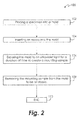
- FIG. 2 illustrates a method, generally indicated at 100, for preparing a metallographic specimen.
- the method 100 includes the step 102 of placing a specimen into the mould 10.
- a metal specimen is placed within the cavity 16 of the mould 10 to begin preparation for examination.
- materials other than metals may be placed within the cavity 16 to be prepared for examination.
- the method 100 includes step 104 of inserting an epoxy into the mould 10.
- a first epoxy portion may be inserted into the mould 10 prior to placing the specimen into the mould 10, and a second epoxy portion may be inserted into the mould 10 after placing the specimen into the mould 10.
- the epoxy includes a low viscosity ultraviolet curable epoxy.
- a low viscosity ultraviolet curable epoxy is inserted into the cavity 16 along with the specimen, either before the specimen is inserted, after the specimen is inserted, or a combination of before the specimen is inserted and after the specimen is inserted.
- the method includes step 106 of exposing the mould 10 to an ultraviolet light for a duration of time to create a mounting sample. Exposing the mounting sample to the ultraviolet light cures the epoxy within the cavity to allow for future examination. It will be appreciated that the mounting sample may be exposed to ultraviolet light from any direction. In one embodiment, the duration of time is less than or equal to approximately four minutes. It will be appreciated that the duration of time may be greater than four minutes. The duration of time to expose the mounting sample to ultraviolet light is dependent, in part, upon the size of the mounting sample (i.e. the depth of penetration of the ultraviolet light). For example, every one half inch of required penetration of ultraviolet light may equate to approximately five minutes of curing time.
- the method further includes step 108 of removing the mounting sample from the mould 10 to be analyzed.
- the mounting sample may be removed from the mould 10 for examining the specimen surface and handling the specimen during further processing of the specimen, such as by cutting and/or polishing, to name just two non-limiting examples.
- the method 100 includes the step of exposing the mounting sample to an ultraviolet light for a duration of time. Curing the mounting sample under ultraviolet light significantly reduces the time required to prepare a sample compared to a cold mounting process, and allows for the creation of a greater quantity of samples compared to a hot mounting process. It will also be appreciated that the mould 10 is formed from a material configured to allow ultraviolet light to penetrate the peripheral walls 12 and bottom 14 into the cavity 16 to aid in curing the epoxy in a shorter amount of time.
Landscapes
- Physics & Mathematics (AREA)
- Health & Medical Sciences (AREA)
- Engineering & Computer Science (AREA)
- Immunology (AREA)
- Life Sciences & Earth Sciences (AREA)
- Biochemistry (AREA)
- General Health & Medical Sciences (AREA)
- General Physics & Mathematics (AREA)
- Chemical & Material Sciences (AREA)
- Pathology (AREA)
- Analytical Chemistry (AREA)
- Electromagnetism (AREA)
- Oral & Maxillofacial Surgery (AREA)
- Thermal Sciences (AREA)
- Toxicology (AREA)
- Manufacturing & Machinery (AREA)
- Mechanical Engineering (AREA)
- Sampling And Sample Adjustment (AREA)
Abstract
Description
- The present disclosure is generally related to metallographic sample preparation, in particular to an improved method for preparing metallographic samples.
- Metallography is the science and art of preparing a metal surface for analysis by grinding and polishing, and etching to reveal the structure of the specimen. Metallographic and materialographic specimen preparation seeks to find the true structure of the material. Mechanical preparation is the most common method of preparing the specimens for examination.
- Mounting of specimens is usually necessary to allow them to be handled easily. It also minimizes the amount of damage likely to be caused to the specimen. Mounting a specimen provides a safe, standardized, and ergonomic way by which to hold a specimen during the grinding and polishing operations. Metallographic specimens are typically mounted using hot mounting or cold mounting. A typical hot mounting cycle will use hot mounting resins and a hot mounting press compressing the mounting media to 4,000 pounds per square inch (28 mPa) and heat to a temperature of 350° Fahrenheit (180° Celsius). Hot mounting samples take approximately ten minutes to process, but only one mount may be processed at a time. Additionally, hot mounting is not suitable for brittle materials (e.g. ceramics), and edge retention is problematic.
- When specimens are very sensitive to pressure or temperature, cold mounts may be made with cold mounting resins. With cold mounting, specimens are placed in a mounting cup and two-part epoxy mounting material is then poured over the specimens. While multiple samples may be made at the same time with cold mounting, it generally take over an hour for the samples to cure.
- Improvements in metallographic sample preparation are therefore needed in the art.
- In one aspect, a sample mould used in a metallographic preparation process includes a body including a peripheral wall and an adjoining bottom surface defining a cavity therein. The mould is formed from a material operative to allow an ultraviolet light to penetrate the peripheral wall and the bottom surface into the cavity. The mould includes a width dimension, and a height dimension. In one embodiment the width dimension is approximately one inch (approximately 30 millimetres) and the height dimension is approximately one half inch (approximately 15 millimetres).
- In one embodiment, the material used to form the mould includes a material transparent to ultraviolet light. In one embodiment, the material is transparent to an ultraviolet light including a wavelength greater than or equal to approximately 250 nanometres. In one embodiment, the transparent material includes silicone.
- In one aspect, a method for preparing a metallographic specimen is provided. The method includes the step of placing a specimen into the mould. The method proceeds to the step of inserting an epoxy into the mould. In one embodiment, a first epoxy portion may be inserted into the mould prior to placing the specimen into the mould, and a second epoxy portion may be inserted into the mould after placing the specimen into the mould. In one embodiment, the epoxy includes a low viscosity ultraviolet curable epoxy.
- The method proceeds to the step of exposing the mould to an ultraviolet light for a duration of time to create a mounting sample. In one embodiment, the duration of time is less than or equal to approximately four minutes. The method further includes the step of removing the mounting sample from the mould to be analyzed.
- The foregoing features and elements may be combined in various combinations without exclusivity, unless expressly indicated otherwise. These features and elements as well as the operation thereof will become more apparent in light of the following description and the accompanying drawings. It should be understood, however, the following description and drawings are intended to be exemplary in nature and non-limiting.
- Other embodiments are also disclosed.
- The embodiments and other features, advantages and disclosures contained herein, and the manner of attaining them, will become apparent and the present disclosure will be better understood by reference to the following description of various exemplary embodiments of the present disclosure taken in conjunction with the accompanying drawings, wherein:
-
FIGS. 1A and 1B are perspective views of a mould used in a metallographic preparation process; and -
FIG. 2 is a schematic flow diagram of an embodiment of a metallographic preparation method. - For the purposes of promoting an understanding of the principles of the present disclosure, reference will now be made to the embodiments illustrated in the drawings, and specific language will be used to describe the same. It will nevertheless be understood that no limitation of the scope of this disclosure is thereby intended.
-
FIGS. 1A and 1B illustrate an embodiment of a sample mould, generally indicated at 10, used in a metallographic preparation process. Themould 10 is configured to house a specimen for preparation and examination. Themould 10 includes a body including aperipheral wall 12 and an adjoiningbottom surface 14 defining acavity 16 therein. Themould 10 is formed from a material operative to allow an ultraviolet light to penetrate theperipheral wall 12 and thebottom surface 14 into thecavity 16. Themould 10 includes awidth dimension 18, as shown inFIG. 1B , and aheight dimension 20. Although it will be appreciated that themould 10 may include any dimension suitable for preparing a specimen, in one embodiment thewidth dimension 18 comprises approximately one inch (approximately 30 millimetres) and theheight dimension 20 comprises approximately one half inch (approximately 15 millimetres). While themould 10 is shown with a circular configuration, it will be appreciated that themould 10 may be formed in any geometric shape or in a combination of different geometric shapes. - In one embodiment, the material used to form the
mould 10 includes a material transparent to ultraviolet light. In one embodiment, the material is transparent to an ultraviolet light including a wavelength greater than or equal to approximately 250 nanometres (approximately 98.43 x 10⁻⁷ inches). In one embodiment, the transparent material includes silicone. It will be appreciated that other transparent materials, such as a clear acrylic to name one non-limiting example, may also be used to form themould 10. -
FIG. 2 illustrates a method, generally indicated at 100, for preparing a metallographic specimen. Themethod 100 includes thestep 102 of placing a specimen into themould 10. For example, a metal specimen is placed within thecavity 16 of themould 10 to begin preparation for examination. It will also be appreciated that materials other than metals may be placed within thecavity 16 to be prepared for examination. - The
method 100 includesstep 104 of inserting an epoxy into themould 10. In one embodiment, a first epoxy portion may be inserted into themould 10 prior to placing the specimen into themould 10, and a second epoxy portion may be inserted into themould 10 after placing the specimen into themould 10. In one embodiment, the epoxy includes a low viscosity ultraviolet curable epoxy. For example, a low viscosity ultraviolet curable epoxy is inserted into thecavity 16 along with the specimen, either before the specimen is inserted, after the specimen is inserted, or a combination of before the specimen is inserted and after the specimen is inserted. - The method includes
step 106 of exposing themould 10 to an ultraviolet light for a duration of time to create a mounting sample. Exposing the mounting sample to the ultraviolet light cures the epoxy within the cavity to allow for future examination. It will be appreciated that the mounting sample may be exposed to ultraviolet light from any direction. In one embodiment, the duration of time is less than or equal to approximately four minutes. It will be appreciated that the duration of time may be greater than four minutes. The duration of time to expose the mounting sample to ultraviolet light is dependent, in part, upon the size of the mounting sample (i.e. the depth of penetration of the ultraviolet light). For example, every one half inch of required penetration of ultraviolet light may equate to approximately five minutes of curing time. - The method further includes
step 108 of removing the mounting sample from themould 10 to be analyzed. For example, after the epoxy has cured from exposure to the ultraviolet light, the mounting sample may be removed from themould 10 for examining the specimen surface and handling the specimen during further processing of the specimen, such as by cutting and/or polishing, to name just two non-limiting examples. - It will be appreciated that as the
method 100 includes the step of exposing the mounting sample to an ultraviolet light for a duration of time. Curing the mounting sample under ultraviolet light significantly reduces the time required to prepare a sample compared to a cold mounting process, and allows for the creation of a greater quantity of samples compared to a hot mounting process. It will also be appreciated that themould 10 is formed from a material configured to allow ultraviolet light to penetrate theperipheral walls 12 and bottom 14 into thecavity 16 to aid in curing the epoxy in a shorter amount of time. - While the invention has been illustrated and described in detail in the drawings and foregoing description, the same is to be considered as illustrative and not restrictive in character, it being understood that only certain embodiments have been shown and described and that all changes and modifications that come within the spirit of the invention are desired to be protected.
Claims (15)
- A method for preparing a metallographic sample, the method comprising the steps of:a) placing a specimen into a mould;b) inserting an epoxy into the mould; andc) exposing the mould to an ultraviolet light for a duration of time to create a mounting sample.
- The method of claim 1, wherein step (b) comprises inserting a first epoxy portion into the mould prior to step (a) and a second epoxy portion into the mould after step (a).
- The method of claim 1 or claim 2, further comprising removing the mounting sample from the mould.
- The method of any preceding claim 1, wherein the mould comprises a material transparent to ultraviolet light.
- The method of claim 4, wherein the material is transparent to an ultraviolet light comprising a wavelength greater than or equal to approximately 250 nanometres.
- The method of claim 4, wherein the transparent material is selected from a group of materials consisting of silicone and clear acrylic.
- The method of any preceding claim, wherein the epoxy comprises a low viscosity ultraviolet curable epoxy.
- The method of any preceding claim, wherein the duration of time is less than or equal to approximately four minutes.
- A mould for use in preparing a metallographic sample comprising a body including a peripheral wall and an adjoining bottom surface defining a cavity therein, the body formed from a material operative to allow an ultraviolet light to penetrate the peripheral wall and the bottom into the cavity.
- The mould of claim 9, wherein the transparent material comprises silicone.
- The mould of claim 9, wherein the transparent material comprises clear acrylic.
- The mould of any of claims 9 to 11, wherein the body includes a height dimension and a width dimension.
- The mould of claim 12, wherein the height dimension is greater than or equal to approximately one inch.
- The mould of claim 12 or claim 13, wherein the width dimension is greater than or equal to approximately one-half inch.
- The mould of any of claims 9 to 14, wherein the ultraviolet light comprises a wavelength greater than or equal to approximately 250 nanometres.
Applications Claiming Priority (1)
| Application Number | Priority Date | Filing Date | Title |
|---|---|---|---|
| US201462058971P | 2014-10-02 | 2014-10-02 |
Publications (2)
| Publication Number | Publication Date |
|---|---|
| EP3002579A1 true EP3002579A1 (en) | 2016-04-06 |
| EP3002579B1 EP3002579B1 (en) | 2023-07-19 |
Family
ID=54707512
Family Applications (1)
| Application Number | Title | Priority Date | Filing Date |
|---|---|---|---|
| EP15188100.0A Active EP3002579B1 (en) | 2014-10-02 | 2015-10-02 | Metallographic sample preparation method and metallographic sample mould |
Country Status (2)
| Country | Link |
|---|---|
| US (1) | US10086536B2 (en) |
| EP (1) | EP3002579B1 (en) |
Cited By (2)
| Publication number | Priority date | Publication date | Assignee | Title |
|---|---|---|---|---|
| CN108168970A (en) * | 2017-12-18 | 2018-06-15 | 西安赛特思迈钛业有限公司 | A kind of cold working method for making sample of metallographic specimen |
| CN108918214A (en) * | 2018-05-17 | 2018-11-30 | 中国石油天然气股份有限公司 | A conglomerate sample preparation method for core analysis and conglomerate sample for core analysis |
Families Citing this family (6)
| Publication number | Priority date | Publication date | Assignee | Title |
|---|---|---|---|---|
| JP7018741B2 (en) * | 2017-11-14 | 2022-02-14 | Jx金属株式会社 | Method for preparing a sample-embedded resin for analysis |
| CN109470543A (en) * | 2018-12-25 | 2019-03-15 | 英利能源(中国)有限公司 | The hot method for embedding of metallographic sample |
| CN111442963A (en) * | 2020-05-09 | 2020-07-24 | 国电锅炉压力容器检验有限公司 | An auxiliary device for on-site metallographic inspection |
| CN114526979B (en) * | 2022-03-01 | 2025-03-11 | 清华大学合肥公共安全研究院 | Two-step hot and cold mounting method for metallographic specimens |
| CN115493915A (en) * | 2022-08-26 | 2022-12-20 | 中铝材料应用研究院有限公司 | A kind of metallographic sample cold mounting mold and using method thereof |
| CN116558932B (en) * | 2023-07-07 | 2023-09-29 | 北京科技大学 | A method for preparing small-sized samples using a large-sized hot mounting machine |
Citations (4)
| Publication number | Priority date | Publication date | Assignee | Title |
|---|---|---|---|---|
| EP0169298A2 (en) * | 1984-07-14 | 1986-01-29 | Kulzer GmbH | Photo-polymerisable material for embedding polished specimens |
| US20070160967A1 (en) * | 2005-11-23 | 2007-07-12 | Halley John A | Apparatus and methods for mounting a specimen in a solid material |
| WO2009118544A2 (en) * | 2008-03-28 | 2009-10-01 | The Secretary Of State For Defence | An optical substrate and sensing chip |
| CN103543060A (en) * | 2012-07-09 | 2014-01-29 | 中国石油化工集团公司 | Corrosion sample inlaying method |
Family Cites Families (1)
| Publication number | Priority date | Publication date | Assignee | Title |
|---|---|---|---|---|
| US7517486B2 (en) * | 2003-05-16 | 2009-04-14 | Du Pont Performance Elastomers L.L.C. | Process for preparing UV curable sealing assemblies |
-
2015
- 2015-08-14 US US14/826,598 patent/US10086536B2/en active Active
- 2015-10-02 EP EP15188100.0A patent/EP3002579B1/en active Active
Patent Citations (4)
| Publication number | Priority date | Publication date | Assignee | Title |
|---|---|---|---|---|
| EP0169298A2 (en) * | 1984-07-14 | 1986-01-29 | Kulzer GmbH | Photo-polymerisable material for embedding polished specimens |
| US20070160967A1 (en) * | 2005-11-23 | 2007-07-12 | Halley John A | Apparatus and methods for mounting a specimen in a solid material |
| WO2009118544A2 (en) * | 2008-03-28 | 2009-10-01 | The Secretary Of State For Defence | An optical substrate and sensing chip |
| CN103543060A (en) * | 2012-07-09 | 2014-01-29 | 中国石油化工集团公司 | Corrosion sample inlaying method |
Cited By (3)
| Publication number | Priority date | Publication date | Assignee | Title |
|---|---|---|---|---|
| CN108168970A (en) * | 2017-12-18 | 2018-06-15 | 西安赛特思迈钛业有限公司 | A kind of cold working method for making sample of metallographic specimen |
| CN108918214A (en) * | 2018-05-17 | 2018-11-30 | 中国石油天然气股份有限公司 | A conglomerate sample preparation method for core analysis and conglomerate sample for core analysis |
| CN108918214B (en) * | 2018-05-17 | 2020-12-01 | 中国石油天然气股份有限公司 | Conglomerate sample preparation method for core analysis and conglomerate sample for core analysis |
Also Published As
| Publication number | Publication date |
|---|---|
| EP3002579B1 (en) | 2023-07-19 |
| US20160096291A1 (en) | 2016-04-07 |
| US10086536B2 (en) | 2018-10-02 |
Similar Documents
| Publication | Publication Date | Title |
|---|---|---|
| US10086536B2 (en) | Metallographic sample preparation method and metallographic sample mold | |
| JP2022017237A (en) | Methods for preparing sliceable cassettes and embedding frames with tissue fixative separable lids, as well as biopsy tissue samples | |
| US20130087945A1 (en) | Method and device for preparing tissue and mould for pretreating tissue material | |
| CN104995498B (en) | For mould and mold apparatus for being embedded in biological specimen in block and associated method | |
| JP2018526632A5 (en) | ||
| CN114728284A (en) | Slicable cassettes and embedding racks with connectors and methods for preparing biopsy samples | |
| EP4393421A3 (en) | Systems and methods for tissue capture and removal | |
| Vogel | Overview on techniques to construct tissue arrays with special emphasis on tissue microarrays | |
| JP2011503519A (en) | Biopsy support with sectionable elastic foam material | |
| CN114526979A (en) | Metallographic specimen cold and hot two-step embedding method | |
| JP2010511889A (en) | Recipient block mold and its uses | |
| JP2004258017A (en) | Array block preparation method, tissue scooping-out device used for the same, and tissue block | |
| US12553806B2 (en) | Method for making a microarray block | |
| EP2851672B1 (en) | Processing method and cassette | |
| WO2010007453A2 (en) | Device and method for embedding biological tissue specimens | |
| Huemer et al. | Long-term live imaging device for improved experimental manipulation of zebrafish larvae | |
| CN108519396A (en) | A kind of preparation method of ultrathin section | |
| JP5409029B2 (en) | Method for confirming dispersibility of short fibers contained in concrete | |
| EP3177905B1 (en) | Method for providing a tissue array using a carrier medium | |
| CN113358453B (en) | Preparation device and method of sample for cable sheath appearance measurement and testing method | |
| CN1346437A (en) | Molded tissue block | |
| EP3064331A3 (en) | Firing process and method | |
| Avci et al. | A flat embedding method to orient thin biological samples for sectioning |
Legal Events
| Date | Code | Title | Description |
|---|---|---|---|
| PUAI | Public reference made under article 153(3) epc to a published international application that has entered the european phase |
Free format text: ORIGINAL CODE: 0009012 |
|
| AK | Designated contracting states |
Kind code of ref document: A1 Designated state(s): AL AT BE BG CH CY CZ DE DK EE ES FI FR GB GR HR HU IE IS IT LI LT LU LV MC MK MT NL NO PL PT RO RS SE SI SK SM TR |
|
| AX | Request for extension of the european patent |
Extension state: BA ME |
|
| RAP1 | Party data changed (applicant data changed or rights of an application transferred) |
Owner name: UNITED TECHNOLOGIES CORPORATION |
|
| 17P | Request for examination filed |
Effective date: 20161003 |
|
| RBV | Designated contracting states (corrected) |
Designated state(s): AL AT BE BG CH CY CZ DE DK EE ES FI FR GB GR HR HU IE IS IT LI LT LU LV MC MK MT NL NO PL PT RO RS SE SI SK SM TR |
|
| STAA | Information on the status of an ep patent application or granted ep patent |
Free format text: STATUS: EXAMINATION IS IN PROGRESS |
|
| 17Q | First examination report despatched |
Effective date: 20210209 |
|
| RAP1 | Party data changed (applicant data changed or rights of an application transferred) |
Owner name: RAYTHEON TECHNOLOGIES CORPORATION |
|
| GRAP | Despatch of communication of intention to grant a patent |
Free format text: ORIGINAL CODE: EPIDOSNIGR1 |
|
| STAA | Information on the status of an ep patent application or granted ep patent |
Free format text: STATUS: GRANT OF PATENT IS INTENDED |
|
| INTG | Intention to grant announced |
Effective date: 20230206 |
|
| GRAS | Grant fee paid |
Free format text: ORIGINAL CODE: EPIDOSNIGR3 |
|
| GRAA | (expected) grant |
Free format text: ORIGINAL CODE: 0009210 |
|
| STAA | Information on the status of an ep patent application or granted ep patent |
Free format text: STATUS: THE PATENT HAS BEEN GRANTED |
|
| AK | Designated contracting states |
Kind code of ref document: B1 Designated state(s): AL AT BE BG CH CY CZ DE DK EE ES FI FR GB GR HR HU IE IS IT LI LT LU LV MC MK MT NL NO PL PT RO RS SE SI SK SM TR |
|
| REG | Reference to a national code |
Ref country code: GB Ref legal event code: FG4D |
|
| REG | Reference to a national code |
Ref country code: CH Ref legal event code: EP |
|
| REG | Reference to a national code |
Ref country code: DE Ref legal event code: R096 Ref document number: 602015084623 Country of ref document: DE |
|
| REG | Reference to a national code |
Ref country code: IE Ref legal event code: FG4D |
|
| RAP4 | Party data changed (patent owner data changed or rights of a patent transferred) |
Owner name: RTX CORPORATION |
|
| REG | Reference to a national code |
Ref country code: LT Ref legal event code: MG9D |
|
| REG | Reference to a national code |
Ref country code: NL Ref legal event code: MP Effective date: 20230719 |
|
| REG | Reference to a national code |
Ref country code: AT Ref legal event code: MK05 Ref document number: 1589915 Country of ref document: AT Kind code of ref document: T Effective date: 20230719 |
|
| PG25 | Lapsed in a contracting state [announced via postgrant information from national office to epo] |
Ref country code: NL Free format text: LAPSE BECAUSE OF FAILURE TO SUBMIT A TRANSLATION OF THE DESCRIPTION OR TO PAY THE FEE WITHIN THE PRESCRIBED TIME-LIMIT Effective date: 20230719 |
|
| PG25 | Lapsed in a contracting state [announced via postgrant information from national office to epo] |
Ref country code: GR Free format text: LAPSE BECAUSE OF FAILURE TO SUBMIT A TRANSLATION OF THE DESCRIPTION OR TO PAY THE FEE WITHIN THE PRESCRIBED TIME-LIMIT Effective date: 20231020 |
|
| PG25 | Lapsed in a contracting state [announced via postgrant information from national office to epo] |
Ref country code: IS Free format text: LAPSE BECAUSE OF FAILURE TO SUBMIT A TRANSLATION OF THE DESCRIPTION OR TO PAY THE FEE WITHIN THE PRESCRIBED TIME-LIMIT Effective date: 20231119 |
|
| PG25 | Lapsed in a contracting state [announced via postgrant information from national office to epo] |
Ref country code: SE Free format text: LAPSE BECAUSE OF FAILURE TO SUBMIT A TRANSLATION OF THE DESCRIPTION OR TO PAY THE FEE WITHIN THE PRESCRIBED TIME-LIMIT Effective date: 20230719 Ref country code: RS Free format text: LAPSE BECAUSE OF FAILURE TO SUBMIT A TRANSLATION OF THE DESCRIPTION OR TO PAY THE FEE WITHIN THE PRESCRIBED TIME-LIMIT Effective date: 20230719 Ref country code: PT Free format text: LAPSE BECAUSE OF FAILURE TO SUBMIT A TRANSLATION OF THE DESCRIPTION OR TO PAY THE FEE WITHIN THE PRESCRIBED TIME-LIMIT Effective date: 20231120 Ref country code: NO Free format text: LAPSE BECAUSE OF FAILURE TO SUBMIT A TRANSLATION OF THE DESCRIPTION OR TO PAY THE FEE WITHIN THE PRESCRIBED TIME-LIMIT Effective date: 20231019 Ref country code: LV Free format text: LAPSE BECAUSE OF FAILURE TO SUBMIT A TRANSLATION OF THE DESCRIPTION OR TO PAY THE FEE WITHIN THE PRESCRIBED TIME-LIMIT Effective date: 20230719 Ref country code: LT Free format text: LAPSE BECAUSE OF FAILURE TO SUBMIT A TRANSLATION OF THE DESCRIPTION OR TO PAY THE FEE WITHIN THE PRESCRIBED TIME-LIMIT Effective date: 20230719 Ref country code: IS Free format text: LAPSE BECAUSE OF FAILURE TO SUBMIT A TRANSLATION OF THE DESCRIPTION OR TO PAY THE FEE WITHIN THE PRESCRIBED TIME-LIMIT Effective date: 20231119 Ref country code: HR Free format text: LAPSE BECAUSE OF FAILURE TO SUBMIT A TRANSLATION OF THE DESCRIPTION OR TO PAY THE FEE WITHIN THE PRESCRIBED TIME-LIMIT Effective date: 20230719 Ref country code: GR Free format text: LAPSE BECAUSE OF FAILURE TO SUBMIT A TRANSLATION OF THE DESCRIPTION OR TO PAY THE FEE WITHIN THE PRESCRIBED TIME-LIMIT Effective date: 20231020 Ref country code: FI Free format text: LAPSE BECAUSE OF FAILURE TO SUBMIT A TRANSLATION OF THE DESCRIPTION OR TO PAY THE FEE WITHIN THE PRESCRIBED TIME-LIMIT Effective date: 20230719 Ref country code: AT Free format text: LAPSE BECAUSE OF FAILURE TO SUBMIT A TRANSLATION OF THE DESCRIPTION OR TO PAY THE FEE WITHIN THE PRESCRIBED TIME-LIMIT Effective date: 20230719 |
|
| PG25 | Lapsed in a contracting state [announced via postgrant information from national office to epo] |
Ref country code: PL Free format text: LAPSE BECAUSE OF FAILURE TO SUBMIT A TRANSLATION OF THE DESCRIPTION OR TO PAY THE FEE WITHIN THE PRESCRIBED TIME-LIMIT Effective date: 20230719 |
|
| REG | Reference to a national code |
Ref country code: DE Ref legal event code: R097 Ref document number: 602015084623 Country of ref document: DE |
|
| PG25 | Lapsed in a contracting state [announced via postgrant information from national office to epo] |
Ref country code: ES Free format text: LAPSE BECAUSE OF FAILURE TO SUBMIT A TRANSLATION OF THE DESCRIPTION OR TO PAY THE FEE WITHIN THE PRESCRIBED TIME-LIMIT Effective date: 20230719 |
|
| PG25 | Lapsed in a contracting state [announced via postgrant information from national office to epo] |
Ref country code: SM Free format text: LAPSE BECAUSE OF FAILURE TO SUBMIT A TRANSLATION OF THE DESCRIPTION OR TO PAY THE FEE WITHIN THE PRESCRIBED TIME-LIMIT Effective date: 20230719 Ref country code: RO Free format text: LAPSE BECAUSE OF FAILURE TO SUBMIT A TRANSLATION OF THE DESCRIPTION OR TO PAY THE FEE WITHIN THE PRESCRIBED TIME-LIMIT Effective date: 20230719 Ref country code: ES Free format text: LAPSE BECAUSE OF FAILURE TO SUBMIT A TRANSLATION OF THE DESCRIPTION OR TO PAY THE FEE WITHIN THE PRESCRIBED TIME-LIMIT Effective date: 20230719 Ref country code: EE Free format text: LAPSE BECAUSE OF FAILURE TO SUBMIT A TRANSLATION OF THE DESCRIPTION OR TO PAY THE FEE WITHIN THE PRESCRIBED TIME-LIMIT Effective date: 20230719 Ref country code: DK Free format text: LAPSE BECAUSE OF FAILURE TO SUBMIT A TRANSLATION OF THE DESCRIPTION OR TO PAY THE FEE WITHIN THE PRESCRIBED TIME-LIMIT Effective date: 20230719 Ref country code: CZ Free format text: LAPSE BECAUSE OF FAILURE TO SUBMIT A TRANSLATION OF THE DESCRIPTION OR TO PAY THE FEE WITHIN THE PRESCRIBED TIME-LIMIT Effective date: 20230719 Ref country code: SK Free format text: LAPSE BECAUSE OF FAILURE TO SUBMIT A TRANSLATION OF THE DESCRIPTION OR TO PAY THE FEE WITHIN THE PRESCRIBED TIME-LIMIT Effective date: 20230719 |
|
| PLBE | No opposition filed within time limit |
Free format text: ORIGINAL CODE: 0009261 |
|
| STAA | Information on the status of an ep patent application or granted ep patent |
Free format text: STATUS: NO OPPOSITION FILED WITHIN TIME LIMIT |
|
| PG25 | Lapsed in a contracting state [announced via postgrant information from national office to epo] |
Ref country code: IT Free format text: LAPSE BECAUSE OF FAILURE TO SUBMIT A TRANSLATION OF THE DESCRIPTION OR TO PAY THE FEE WITHIN THE PRESCRIBED TIME-LIMIT Effective date: 20230719 Ref country code: MC Free format text: LAPSE BECAUSE OF FAILURE TO SUBMIT A TRANSLATION OF THE DESCRIPTION OR TO PAY THE FEE WITHIN THE PRESCRIBED TIME-LIMIT Effective date: 20230719 |
|
| REG | Reference to a national code |
Ref country code: CH Ref legal event code: PL |
|
| REG | Reference to a national code |
Ref country code: BE Ref legal event code: MM Effective date: 20231031 |
|
| PG25 | Lapsed in a contracting state [announced via postgrant information from national office to epo] |
Ref country code: LU Free format text: LAPSE BECAUSE OF NON-PAYMENT OF DUE FEES Effective date: 20231002 |
|
| 26N | No opposition filed |
Effective date: 20240422 |
|
| PG25 | Lapsed in a contracting state [announced via postgrant information from national office to epo] |
Ref country code: LU Free format text: LAPSE BECAUSE OF NON-PAYMENT OF DUE FEES Effective date: 20231002 |
|
| PG25 | Lapsed in a contracting state [announced via postgrant information from national office to epo] |
Ref country code: CH Free format text: LAPSE BECAUSE OF NON-PAYMENT OF DUE FEES Effective date: 20231031 |
|
| PG25 | Lapsed in a contracting state [announced via postgrant information from national office to epo] |
Ref country code: CH Free format text: LAPSE BECAUSE OF NON-PAYMENT OF DUE FEES Effective date: 20231031 Ref country code: SI Free format text: LAPSE BECAUSE OF FAILURE TO SUBMIT A TRANSLATION OF THE DESCRIPTION OR TO PAY THE FEE WITHIN THE PRESCRIBED TIME-LIMIT Effective date: 20230719 |
|
| PG25 | Lapsed in a contracting state [announced via postgrant information from national office to epo] |
Ref country code: BE Free format text: LAPSE BECAUSE OF NON-PAYMENT OF DUE FEES Effective date: 20231031 |
|
| PG25 | Lapsed in a contracting state [announced via postgrant information from national office to epo] |
Ref country code: IE Free format text: LAPSE BECAUSE OF NON-PAYMENT OF DUE FEES Effective date: 20231002 |
|
| PG25 | Lapsed in a contracting state [announced via postgrant information from national office to epo] |
Ref country code: IE Free format text: LAPSE BECAUSE OF NON-PAYMENT OF DUE FEES Effective date: 20231002 |
|
| PG25 | Lapsed in a contracting state [announced via postgrant information from national office to epo] |
Ref country code: BG Free format text: LAPSE BECAUSE OF FAILURE TO SUBMIT A TRANSLATION OF THE DESCRIPTION OR TO PAY THE FEE WITHIN THE PRESCRIBED TIME-LIMIT Effective date: 20230719 |
|
| PG25 | Lapsed in a contracting state [announced via postgrant information from national office to epo] |
Ref country code: BG Free format text: LAPSE BECAUSE OF FAILURE TO SUBMIT A TRANSLATION OF THE DESCRIPTION OR TO PAY THE FEE WITHIN THE PRESCRIBED TIME-LIMIT Effective date: 20230719 |
|
| PG25 | Lapsed in a contracting state [announced via postgrant information from national office to epo] |
Ref country code: CY Free format text: LAPSE BECAUSE OF FAILURE TO SUBMIT A TRANSLATION OF THE DESCRIPTION OR TO PAY THE FEE WITHIN THE PRESCRIBED TIME-LIMIT; INVALID AB INITIO Effective date: 20151002 |
|
| PG25 | Lapsed in a contracting state [announced via postgrant information from national office to epo] |
Ref country code: HU Free format text: LAPSE BECAUSE OF FAILURE TO SUBMIT A TRANSLATION OF THE DESCRIPTION OR TO PAY THE FEE WITHIN THE PRESCRIBED TIME-LIMIT; INVALID AB INITIO Effective date: 20151002 |
|
| REG | Reference to a national code |
Ref country code: DE Ref legal event code: R081 Ref document number: 602015084623 Country of ref document: DE Owner name: RTX CORPORATION (N.D.GES.D. STAATES DELAWARE),, US Free format text: FORMER OWNER: RAYTHEON TECHNOLOGIES CORPORATION, FARMINGTON, CT, US |
|
| PGFP | Annual fee paid to national office [announced via postgrant information from national office to epo] |
Ref country code: GB Payment date: 20250923 Year of fee payment: 11 |
|
| PGFP | Annual fee paid to national office [announced via postgrant information from national office to epo] |
Ref country code: FR Payment date: 20250924 Year of fee payment: 11 |
|
| PG25 | Lapsed in a contracting state [announced via postgrant information from national office to epo] |
Ref country code: TR Free format text: LAPSE BECAUSE OF FAILURE TO SUBMIT A TRANSLATION OF THE DESCRIPTION OR TO PAY THE FEE WITHIN THE PRESCRIBED TIME-LIMIT Effective date: 20230719 |
|
| PGFP | Annual fee paid to national office [announced via postgrant information from national office to epo] |
Ref country code: DE Payment date: 20250923 Year of fee payment: 11 |