EP3002544B1 - Priming machine for cartridges with a metal case - Google Patents
Priming machine for cartridges with a metal case Download PDFInfo
- Publication number
- EP3002544B1 EP3002544B1 EP15187176.1A EP15187176A EP3002544B1 EP 3002544 B1 EP3002544 B1 EP 3002544B1 EP 15187176 A EP15187176 A EP 15187176A EP 3002544 B1 EP3002544 B1 EP 3002544B1
- Authority
- EP
- European Patent Office
- Prior art keywords
- case
- head
- cases
- primer
- machine
- Prior art date
- Legal status (The legal status is an assumption and is not a legal conclusion. Google has not performed a legal analysis and makes no representation as to the accuracy of the status listed.)
- Not-in-force
Links
- 230000037452 priming Effects 0.000 title claims description 32
- 239000002184 metal Substances 0.000 title claims description 15
- 238000003780 insertion Methods 0.000 claims description 15
- 230000037431 insertion Effects 0.000 claims description 15
- 230000008878 coupling Effects 0.000 claims description 6
- 238000010168 coupling process Methods 0.000 claims description 6
- 238000005859 coupling reaction Methods 0.000 claims description 6
- 238000006073 displacement reaction Methods 0.000 description 6
- 238000004519 manufacturing process Methods 0.000 description 5
- 230000008901 benefit Effects 0.000 description 3
- 239000003721 gunpowder Substances 0.000 description 3
- 239000004033 plastic Substances 0.000 description 3
- 239000000843 powder Substances 0.000 description 3
- 229910000851 Alloy steel Inorganic materials 0.000 description 2
- 229910001369 Brass Inorganic materials 0.000 description 2
- 239000010951 brass Substances 0.000 description 2
- 238000004880 explosion Methods 0.000 description 2
- 239000000203 mixture Substances 0.000 description 2
- 230000000284 resting effect Effects 0.000 description 2
- 239000004429 Calibre Substances 0.000 description 1
- 238000010276 construction Methods 0.000 description 1
- 230000006378 damage Effects 0.000 description 1
- 230000001419 dependent effect Effects 0.000 description 1
- 230000000694 effects Effects 0.000 description 1
- 239000002360 explosive Substances 0.000 description 1
- 230000002452 interceptive effect Effects 0.000 description 1
- 238000003754 machining Methods 0.000 description 1
- 239000007769 metal material Substances 0.000 description 1
- 238000000034 method Methods 0.000 description 1
- 239000003380 propellant Substances 0.000 description 1
- 230000002441 reversible effect Effects 0.000 description 1
- 238000007493 shaping process Methods 0.000 description 1
Images


Classifications
-
- F—MECHANICAL ENGINEERING; LIGHTING; HEATING; WEAPONS; BLASTING
- F42—AMMUNITION; BLASTING
- F42B—EXPLOSIVE CHARGES, e.g. FOR BLASTING, FIREWORKS, AMMUNITION
- F42B33/00—Manufacture of ammunition; Dismantling of ammunition; Apparatus therefor
- F42B33/001—Devices or processes for assembling ammunition, cartridges or cartridge elements from parts
-
- F—MECHANICAL ENGINEERING; LIGHTING; HEATING; WEAPONS; BLASTING
- F42—AMMUNITION; BLASTING
- F42B—EXPLOSIVE CHARGES, e.g. FOR BLASTING, FIREWORKS, AMMUNITION
- F42B33/00—Manufacture of ammunition; Dismantling of ammunition; Apparatus therefor
- F42B33/04—Fitting or extracting primers in or from fuzes or charges
Definitions
- the invention relates to the sector of machines for the production and loading of ammunition, and particularly of cartridges used in the sports and military sectors.
- the invention concerns a priming machine for cartridges with a metal case, particularly of the type made of brass and steel alloys, designed to insert primer cups inside the head of said case.
- priming machines for cartridges substantially comprise a supporting frame, means for feeding a plurality of metal cases and a corresponding plurality of primer cups, means for pushing said primer cups inside said metal cases, and means for moving and ejecting the cases once they are complete with a primer.
- Such machines also comprise motor means for driving said feeding, moving and ejecting means.
- the primer cup is placed, with the bottom of the cup uppermost, on the outer surface of the head, which faces upwards.
- the push means provided on the priming machines push the primer cup inside the seat provided on the head of the case.
- the push means traditionally comprise two pistons: a first piston is designed to slide inside the hollow body of the case and cooperate with the inner surface of the head; a second, opposing piston is designed to cooperate with the bottom of the primer cup to keep it in position during the insertion of the head inside the seat.
- the piston inside the case cooperates with the opposing piston to enable a stable interference coupling of the cup with the case.
- the first piston inserted inside the case, brings a pushing force to bear on the inner surface of the head that enables a pre-set amount of vertical movement of the whole case.
- the length of this movement is usually calculated as a function of the height of the primer cup to be inserted.
- the primer cup For the firearm, i.e. both the striker and the breechblock, to function properly, the primer cup must be fully inserted in its seat with the bottom of the cup a pre-set distance (specified by the manufacturer) further inside the case in relation to the plane identified by the outer surface of the head of the case. Said distance is specified as a function of the type of ammunition and of the type of firearm in which it is used. The positioning tolerance is approximately 0.03 mm.
- the main problem lies in the difficulty of inserting the primer cup precisely and at the right distance inside the seat provided on the head of the case.
- a disadvantage of currently-used priming machines lies in that they rely on the inner surface of the head of the case as a reference plane to define the movement of the case being pushed by the piston.
- the distance between the inner surface and the outer surface, and the depth of the seat for containing the cup may vary from one case to another, even for cartridges of the same calibre.
- the manufacture of these cases includes a drawing phase in their machining and shaping, and this operation cannot assure a constant dimensional precision for all the cases.
- This drawing phase consists in converting a flat sheet of rolled metal material into a hollow object of more or less complex shape by means of one or more steps completed inside moulds.
- This drawing process induces a variation in the thickness of the original sheet, leading to the manufacture of cases that are of different thicknesses in various places. This makes it very difficult to obtain cases of constant thickness, even when the allowable dimensional tolerances are met.
- the need to achieve a coupling with such a narrow tolerance is incompatible with the unavoidable dimensional inaccuracies of the various cases, and the operation cannot be guaranteed if the inner surface of the head is used as the reference plane to calculate the movement of the piston because it often varies from one case to another.
- the feed means are arranged so that the cases move forward on a lower level with the opening in the hollow body facing downwards, while the cups advance on a higher level with their loading side facing downwards, and therefore always towards the inside of the machine, where its working parts are located.
- This manual machine disadvantageously, has to delegate to the user's ability the correct dosage of the force needed by the piston, thus the machine is not able to guarantee the maximum working precision.
- the invention proposes to overcome these drawbacks by means of a priming machine for cartridges with a metal case that is efficient and precise in the manufacturing phases; that enables properly assembled cases that comply with the required dimensional tolerances to be obtained, and that guarantees the utmost safety for operators, the working environment and the machine itself.
- a priming machine for cartridges with a metal case comprising:
- said movable upper surface comprises elastic means adapted to enable the reversibility of its movement.
- Said movable upper surface advantageously comprises stop means adapted to define the maximum length of the movement of said cases according to the height of said primer cups.
- said piston is divided into two portions connected together in a telescopic manner, with the interposition of elastic means.
- said elastic means interposed in said telescopic connection comprise disc springs.
- the main advantage of the invention derives from having changed the reference plane used to calculate the amount of movement of the case, having made it no longer dependent on the geometrical structure and internal dimensions of the case.
- the cup remains at a standstill while the head is lowered onto and around the cup.
- Pre-setting the maximum length of this movement, and particularly of the lowering of the surface on which the case rests, by means of an appropriate positioning of the stop means guarantees the uniformity of assembly of all the cases, optimising their production.
- the elastically yielding piston enables any excess pushing force to be absorbed and compensates for the more ample movement induced by the machine on the piston in relation to the distance by which the surface on which the head of the case rests is lowered.
- Feeding the cases from above and keeping the underlying cups resting on the fixed surface with their open end facing upwards offer important safety benefits for the machine and its operators, since there is no longer any risk of gunpowder falling out and dropping inside the machine.
- Said priming machine 1 essentially comprises a support frame 3 on which there are: feed means 4 for a plurality of metal cases 2, and feed means 8 for a plurality of primer cups 7; means for pushing said primer cups 7 inside the head 6 of said cases 2; means for moving and ejecting the cartridges once complete with primers.
- Said priming machine 1 comprises a plurality of stations 17 where the primer cups are inserted in the bottoms of the cases, positioned in a circular arrangement. Said machine is therefore designed to operate in a continuous cycle because each insertion station 17 corresponds to a precise insertion phase.
- Said feed means 8 for said plurality of primer cups 7 are provided along the lower portion of said machine 1, underneath the feed means 4 for said plurality of cases 2.
- Said machine 1 is also equipped with motor means and a control unit designed to superintend all the machine's functions.
- Figures 3 and 5 refer to a station in which the case 2 and the primer cup 7 are simply positioned so as to be axially aligned, one above the other;
- Figures 4 and 6 refer instead to a station where the push means located inside the case are actually inserting the primer cup 7 in the head 6.
- Said metal cases 2 comprise a hollow body 5 in the shape of a truncated cone with a longitudinal axis of symmetry, closed underneath by a flat head 6 that is shaped centrally to form a seat 16 designed to contain a primer cup 7.
- said push means comprise a movable piston 9 connected to said motor means, which enable a reversible movement of vertical displacement.
- Said piston 9 is elastically yielding, being composed of two telescopically connected portions 10', 10" with the interposition of elastic means.
- said priming machine 1 comprises a fixed lower surface 11, of circular shape, supporting the primer cup 7 coming from the respective feed means 8.
- Said fixed lower surface 11 has a diameter substantially equating to the diameter of the base of said primer cup 7.
- said primer cups 7 rest on the fixed lower surface 11 oriented with their closing seals facing upwards, so that the priming mixture remains contained inside the hollow body of the cup and is not spilt inside the machine ( Figures 3 and 5 ).
- said priming machine 1 also comprises an un movable upper surface 12, shaped in the form of a circular crown, which supports the head 6 of the case 2 to be primed.
- Said movable circular crown is designed so that it can fit around the corresponding fixed lower surface 11 of circular shape.
- said movable upper surface 12 in the shape of a circular crown supports the outer surface 6" of the head 6 surrounding the seat 16 for containing the cups 7, which is also in the shape of a circular crown.
- Said movable upper surface 12 is designed to enable the vertical displacement of each case 2 due to the effect of the pushing force brought to bear on the case by the piston 9.
- the lowering of said movable surface 12 is thus designed to enable a displacement ⁇ of each case 2 defined in relation to the fixed surface 11 supporting the respective primer cup 7.
- the case 2 advantageously moves by a defined quantity ⁇ that is pre-set during the construction of the machine by means of the appropriate positioning of the stop means 14.
- Said stop means 14 consist of the base of the priming machine 1, and the movement ⁇ that the movable surface 12 can perform is determined by the structural distance, established during the assembly of the machine, between said base and the underside of said movable surface.
- the elastic means and, to be specific, helical springs 13 located underneath said movable surface 12, ensure the reversibility of the downward movement of said surface.
Landscapes
- Engineering & Computer Science (AREA)
- Manufacturing & Machinery (AREA)
- General Engineering & Computer Science (AREA)
- Portable Nailing Machines And Staplers (AREA)
Description
- The invention relates to the sector of machines for the production and loading of ammunition, and particularly of cartridges used in the sports and military sectors.
- More in detail, the invention concerns a priming machine for cartridges with a metal case, particularly of the type made of brass and steel alloys, designed to insert primer cups inside the head of said case.
- The case substantially comprises a hollow body, generally of a truncated cone or substantially conical shape, that contains the gunpowder, closed on the underside by a flat head that is centrally shaped with a perforated seat adapted to contain a primer cup, i.e. a small charge that, when hit by the striker of the firearm, makes the main charge of propellant explode.
- According to the known art, priming machines for cartridges substantially comprise a supporting frame, means for feeding a plurality of metal cases and a corresponding plurality of primer cups, means for pushing said primer cups inside said metal cases, and means for moving and ejecting the cases once they are complete with a primer.
- Such machines also comprise motor means for driving said feeding, moving and ejecting means.
- All movements and the synchronism between the various machine components are managed by an appropriate electronic unit for controlling its electromechanical parts.
- During the feeding of the components to be assembled, the primer cup is placed, with the bottom of the cup uppermost, on the outer surface of the head, which faces upwards.
- The push means provided on the priming machines push the primer cup inside the seat provided on the head of the case. The push means traditionally comprise two pistons: a first piston is designed to slide inside the hollow body of the case and cooperate with the inner surface of the head; a second, opposing piston is designed to cooperate with the bottom of the primer cup to keep it in position during the insertion of the head inside the seat.
- The piston inside the case cooperates with the opposing piston to enable a stable interference coupling of the cup with the case.
- The first piston, inserted inside the case, brings a pushing force to bear on the inner surface of the head that enables a pre-set amount of vertical movement of the whole case. The length of this movement is usually calculated as a function of the height of the primer cup to be inserted.
- Such priming machines have several drawbacks and disadvantages.
- For the firearm, i.e. both the striker and the breechblock, to function properly, the primer cup must be fully inserted in its seat with the bottom of the cup a pre-set distance (specified by the manufacturer) further inside the case in relation to the plane identified by the outer surface of the head of the case. Said distance is specified as a function of the type of ammunition and of the type of firearm in which it is used. The positioning tolerance is approximately 0.03 mm.
- The main problem lies in the difficulty of inserting the primer cup precisely and at the right distance inside the seat provided on the head of the case.
- A disadvantage of currently-used priming machines lies in that they rely on the inner surface of the head of the case as a reference plane to define the movement of the case being pushed by the piston. Unfortunately, the distance between the inner surface and the outer surface, and the depth of the seat for containing the cup, may vary from one case to another, even for cartridges of the same calibre. In fact, the manufacture of these cases includes a drawing phase in their machining and shaping, and this operation cannot assure a constant dimensional precision for all the cases.
- This drawing phase consists in converting a flat sheet of rolled metal material into a hollow object of more or less complex shape by means of one or more steps completed inside moulds. This drawing process induces a variation in the thickness of the original sheet, leading to the manufacture of cases that are of different thicknesses in various places. This makes it very difficult to obtain cases of constant thickness, even when the allowable dimensional tolerances are met.
- Since conventional priming machines use a case-cup coupling system that involves relying on the inner surface of the head as a reference plane to establish the length of the movement needed to ensure that the case incorporates the cup, any dimensional variations in the hollow body of the case, such as different heights of the head or different depths of the seat, will give rise to an imprecise positioning of the cup inside its seat.
- There is consequently a risk of the primer cup being pushed too far inside the head of the case or, worse still, it may remain partially outside the case, with the risk of it being accidentally bumped and broken, or damaged and interfering with the explosion of the gunpowder, or giving rise to firearm jamming or malfunctioning.
- Disadvantageously, the need to achieve a coupling with such a narrow tolerance is incompatible with the unavoidable dimensional inaccuracies of the various cases, and the operation cannot be guaranteed if the inner surface of the head is used as the reference plane to calculate the movement of the piston because it often varies from one case to another.
- A further drawback of the known art concerns the safety of the machine as a whole, and stems from the orientation of the cups and cases during their feeding and handling in traditional priming machines.
- The feed means are arranged so that the cases move forward on a lower level with the opening in the hollow body facing downwards, while the cups advance on a higher level with their loading side facing downwards, and therefore always towards the inside of the machine, where its working parts are located.
- Disadvantageously, during the handling of the cups, there is a risk of the priming powder escaping from the side facing downwards, which is not always perfectly sealed. As a consequence, it is easy for the sliding surfaces of the machine to be soiled by the powder falling out, making clean and servicing operations continuously necessary.
- An even greater disadvantage lies in that any build-up of the explosive powder is very dangerous; it can cause fire, trigger explosions and lead to accidents and injuries.
- Document
US 2 748 648 A discloses a manual priming machine for cartridges with a plastic case comprising: - a support frame;
- a plurality of plastic cases comprising a hollow body having a longitudinal axis of symmetry and a head shaped so as to contain a primer cup;
- a plurality of primer cups;
- push means for pushing said primer cups inside the head of said plastic cases, comprising a piston adapted to cooperate with the inner surface of the head of the case to move said case vertically in relation to a reference plane and to allow mutual forced coupling of a cup inside a case.
- Said priming machine comprises a fixed bottom surface on which said primer cups rest and an upper surface, movable along the axis of the cases, on which the head of said cases rests: said movable upper surface is adapted to allow a given vertical movement of each case in relation to the corresponding underlying primer cup, thereby enabling the outer surface of said head to be used as reference plane for the insertion of said primer cup inside said case.
- This manual machine, disadvantageously, has to delegate to the user's ability the correct dosage of the force needed by the piston, thus the machine is not able to guarantee the maximum working precision.
- The invention proposes to overcome these drawbacks by means of a priming machine for cartridges with a metal case that is efficient and precise in the manufacturing phases; that enables properly assembled cases that comply with the required dimensional tolerances to be obtained, and that guarantees the utmost safety for operators, the working environment and the machine itself.
- These objectives are achieved with a priming machine for cartridges with a metal case comprising:
- a supporting frame;
- feed means for feeding a plurality of metal cases comprising a hollow body having a longitudinal axis of symmetry and a head shaped so as to contain a primer cup;
- feed means for feeding a plurality of primer cups;
- push means for pushing said primer cups inside the head of said metal cases, comprising
a piston adapted to cooperate with the inner surface of the head of the case in order to move said case vertically in relation to a reference plane and to allow the mutual forced coupling of a cup inside a case, wherein said priming machine comprises a fixed bottom surface on which said primer cups rest and an upper surface, movable along the axis of the cases on which the head of said cases rests, wherein said movable upper surface is adapted to allow a given vertical movement of each case in relation to the corresponding underlying primer cup, thereby enabling the outer surface of said head to be used as the reference plane for the insertion of said primer cup inside said case, characterized in that said priming machine further comprises:- means for moving and ejecting the primed cases;
- motor means;
- a machine control unit,
and in that said piston is elastically yielding.
- According to a first aspect of the invention, said movable upper surface comprises elastic means adapted to enable the reversibility of its movement.
- Said movable upper surface advantageously comprises stop means adapted to define the maximum length of the movement of said cases according to the height of said primer cups.
- In particular, said piston is divided into two portions connected together in a telescopic manner, with the interposition of elastic means.
- In a preferred embodiment, said elastic means interposed in said telescopic connection comprise disc springs.
- The main advantage of the invention derives from having changed the reference plane used to calculate the amount of movement of the case, having made it no longer dependent on the geometrical structure and internal dimensions of the case.
- Though still pushing from the inside of the hollow body of the case, it uses as a reference plane the outer surface of the head, and this guarantees a constant, equal and correct insertion of the cup inside the head below its reference surface, irrespective of the dimensional tolerances of the inside of the case.
- During the actual insertion of the primer, the cup remains at a standstill while the head is lowered onto and around the cup.
- Pre-setting the maximum length of this movement, and particularly of the lowering of the surface on which the case rests, by means of an appropriate positioning of the stop means guarantees the uniformity of assembly of all the cases, optimising their production.
- The elastically yielding piston enables any excess pushing force to be absorbed and compensates for the more ample movement induced by the machine on the piston in relation to the distance by which the surface on which the head of the case rests is lowered.
- Feeding the cases from above and keeping the underlying cups resting on the fixed surface with their open end facing upwards offer important safety benefits for the machine and its operators, since there is no longer any risk of gunpowder falling out and dropping inside the machine.
- Moreover, the cup is always kept resting on the feed line and does not run any risk of being damaged during its handling.
- The advantages of the invention will emerge more clearly in the following description of a preferred embodiment, given as a non-limiting example, with the aid of the figures wherein:
-
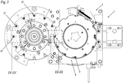
Figures 1 and2 show vertical and horizontal sections, respectively, of a priming machine for cartridges with a metal case according to the invention; -
Figures 3 and 4 show a vertical section of a detail of the machine inFigs. 1 and2 , coming within the dotted lines III-III and IV-IV, in two different working positions; -
Figures 5 and 6 show a vertical section, with slightly deformed proportions for the sake of clarity, of details drawn fromFigures 3 and 4 , respectively. - With reference to
Figures 1 and2 , showing a priming machine 1 for cartridges with ametal case 2, generally made of brass and steel alloy, and used in the sporting and military sectors. - Said priming machine 1 essentially comprises a support frame 3 on which there are: feed means 4 for a plurality of
metal cases 2, and feed means 8 for a plurality ofprimer cups 7; means for pushing said primer cups 7 inside thehead 6 of saidcases 2; means for moving and ejecting the cartridges once complete with primers. - Said priming machine 1 comprises a plurality of
stations 17 where the primer cups are inserted in the bottoms of the cases, positioned in a circular arrangement. Said machine is therefore designed to operate in a continuous cycle because eachinsertion station 17 corresponds to a precise insertion phase. - Said feed means 8 for said plurality of
primer cups 7 are provided along the lower portion of said machine 1, underneath the feed means 4 for said plurality ofcases 2. - Said feed means 8 for said plurality of
primer cups 7 and said feed means 4 for said plurality ofcases 2 converge towards saidinsertion stations 17. - Said machine 1 is also equipped with motor means and a control unit designed to superintend all the machine's functions.
- With particular reference to the detailed cross sections of
Figures 3 and 4 , and even more specifically in the enlarged cross sections ofFigures 5 and 6 , saidinsertion stations 17 can be seen in two distinct working stages:Figures 3 and 5 refer to a station in which thecase 2 and theprimer cup 7 are simply positioned so as to be axially aligned, one above the other;Figures 4 and 6 refer instead to a station where the push means located inside the case are actually inserting theprimer cup 7 in thehead 6. - Said
metal cases 2 comprise a hollow body 5 in the shape of a truncated cone with a longitudinal axis of symmetry, closed underneath by aflat head 6 that is shaped centrally to form aseat 16 designed to contain aprimer cup 7. - Said
primer cups 7 likewise comprise a cylindrical hollow body of limited height in relation to the dimensions of the cases, and a seal for closing said hollow body designed to retain the priming mixture inside it. - The remainder of this description concerns the components of a
generic insertion station 17. - For each
insertion station 17 of said priming machine 1, said push means comprise amovable piston 9 connected to said motor means, which enable a reversible movement of vertical displacement. -
Said piston 9 is designed to cooperate with the inner surface 6' of thehead 6 of thecase 2, to facilitate its displacement. -
Said piston 9 is elastically yielding, being composed of two telescopically connectedportions 10', 10" with the interposition of elastic means. - Said elastic means comprise disc springs 15 chosen in number and size as a function of the type and dimension of the
case 2 to be primed. - In line with each
insertion station 17, said priming machine 1 comprises a fixedlower surface 11, of circular shape, supporting theprimer cup 7 coming from the respective feed means 8. Said fixedlower surface 11 has a diameter substantially equating to the diameter of the base of saidprimer cup 7. - Generally speaking, said primer cups 7 rest on the fixed
lower surface 11 oriented with their closing seals facing upwards, so that the priming mixture remains contained inside the hollow body of the cup and is not spilt inside the machine (Figures 3 and 5 ). - Again in line with each
insertion station 17, said priming machine 1 also comprises an un movableupper surface 12, shaped in the form of a circular crown, which supports thehead 6 of thecase 2 to be primed. Said movable circular crown is designed so that it can fit around the corresponding fixedlower surface 11 of circular shape. - In particular, said movable
upper surface 12 in the shape of a circular crown supports theouter surface 6" of thehead 6 surrounding theseat 16 for containing thecups 7, which is also in the shape of a circular crown. - Said movable
upper surface 12 is designed to enable the vertical displacement of eachcase 2 due to the effect of the pushing force brought to bear on the case by thepiston 9. - The lowering of said
movable surface 12 is thus designed to enable a displacement Δ of eachcase 2 defined in relation to the fixedsurface 11 supporting therespective primer cup 7. - This displacement movement enables the
case 2 to incorporate saidcup 7, by forced interference, inside theseat 16 in the head 6 (Figures 4 and 6 ). - Irrespective of the force delivered by the motor means and brought to bear by the
piston 9 on the inner surface 6' of thehead 6, thecase 2 advantageously moves by a defined quantity Δ that is pre-set during the construction of the machine by means of the appropriate positioning of the stop means 14. - Said stop means 14 consist of the base of the priming machine 1, and the movement Δ that the
movable surface 12 can perform is determined by the structural distance, established during the assembly of the machine, between said base and the underside of said movable surface. - Any excess force brought to bear by the
piston 9 is absorbed by the disc springs 15 inserted in the telescopic connection between thecomponents 10', 10" of thepiston 9, which enable the piston to absorb any dimensional differences inside thecase 2, while always completing the full displacement Δ required to ensure the appropriate positioning of theprimer cup 7 inside theseat 16 in thehead 6 of thecase 2. - Being able to compensate for said force by means of the disc springs 15 makes it unnecessary to set particular parameters for said motor means, which may consequently always bring the same amount of pressure to bear on the
piston 9. - In addition, to ensure the appropriate insertion of the
cup 7 inside thecase 2, irrespective of the dimensions of the cases, it is only necessary to set the maximum extent of the movement Δ of themovable surface 12 as the height h of the cup plus a few millimetres (specified by the manufacturer), such that the cup fits well within theseat 16 in the head, bearing in mind the tolerances. - The elastic means and, to be specific,
helical springs 13 located underneath saidmovable surface 12, ensure the reversibility of the downward movement of said surface. - After positioning the
cup 7 in theseat 16 of thehead 6, thepiston 9 and themovable surface 12 move upwards, releasing thecase 2 so that it can be forwarded to the moving and ejecting means.
Claims (5)
- A priming machine (1) for cartridges with a metal case comprising:- a support frame (3);- feed means (4) for feeding a plurality of metal cases (2) comprising a hollow body (5) having a longitudinal axis of symmetry and a head (6) shaped so as to contain a primer cup (7);- feed means (8) for feeding a plurality of primer cups (7);- push means for pushing said primer cups (7) inside the head (6) of said metal cases (2), comprising a piston (9) adapted to cooperate with the inner surface (6') of the head (6) of the case (2) to move said case (2) vertically in relation to a reference plane and to allow mutual forced coupling of a cup (7) inside a case (2),wherein said priming machine (1) comprises a fixed bottom surface (11) on which said primer cups (7) rest and an upper surface (12), movable along the axis of the cases (2), on which the head (6) of said cases rests, wherein said movable upper surface (12) is adapted to allow a given vertical movement (Δ) of each case (2) in relation to the corresponding underlying primer cup (7), thereby enabling the outer surface (6") of said head (6) to be used as reference plane for the insertion of said primer cup (7) inside said case (2), characterized in that said priming machine further comprises:- means for moving and ejecting the primed cases;- motor means;- a machine control unit,and in that said piston (9) is elastically yielding.
- The priming machine (1) according to claim 1, characterized in that said movable upper surface (12) comprises elastic means (13) adapted to enable the reversibility of its movement.
- The priming machine (1) according to claim 1, characterized in that said movable upper surface (12) comprises stop means (14) adapted to define the maximum length of the movement (Δ) of said cases (2) according to the height (h) of said primer cups (7).
- The priming machine (1) according to claim 1, characterized in that said piston (9) is divided into two portions (10', 10") connected together in a telescopic manner with the interposition of elastic means.
- The priming machine (1) according to claim 4, characterized in that said elastic means interposed in said telescopic connection comprise disc springs (15).
Applications Claiming Priority (1)
| Application Number | Priority Date | Filing Date | Title |
|---|---|---|---|
| ITCR20140023 | 2014-09-30 |
Publications (2)
| Publication Number | Publication Date |
|---|---|
| EP3002544A1 EP3002544A1 (en) | 2016-04-06 |
| EP3002544B1 true EP3002544B1 (en) | 2017-06-28 |
Family
ID=52101405
Family Applications (1)
| Application Number | Title | Priority Date | Filing Date |
|---|---|---|---|
| EP15187176.1A Not-in-force EP3002544B1 (en) | 2014-09-30 | 2015-09-28 | Priming machine for cartridges with a metal case |
Country Status (1)
| Country | Link |
|---|---|
| EP (1) | EP3002544B1 (en) |
Cited By (1)
| Publication number | Priority date | Publication date | Assignee | Title |
|---|---|---|---|---|
| US20210215467A1 (en) * | 2020-01-15 | 2021-07-15 | Randy J. Jones | Table top priming machine for small caliber ammunition |
Families Citing this family (2)
| Publication number | Priority date | Publication date | Assignee | Title |
|---|---|---|---|---|
| CN107840773B (en) * | 2017-12-01 | 2020-11-03 | 四川德鑫源机器人有限公司 | A detonator automatic pipe arranging machine |
| US11204226B1 (en) | 2020-09-30 | 2021-12-21 | John D. Lee | Automatic case fed priming tool |
Family Cites Families (2)
| Publication number | Priority date | Publication date | Assignee | Title |
|---|---|---|---|---|
| US2748648A (en) * | 1953-05-11 | 1956-06-05 | Willis C Miller | Sizing and priming device for shotgun shells |
| FR2519946B1 (en) * | 1982-01-20 | 1986-01-31 | Manurhin |
-
2015
- 2015-09-28 EP EP15187176.1A patent/EP3002544B1/en not_active Not-in-force
Cited By (2)
| Publication number | Priority date | Publication date | Assignee | Title |
|---|---|---|---|---|
| US20210215467A1 (en) * | 2020-01-15 | 2021-07-15 | Randy J. Jones | Table top priming machine for small caliber ammunition |
| US11768064B2 (en) * | 2020-01-15 | 2023-09-26 | Bitterroot Tool & Machine, Inc. | Table top priming machine for small caliber ammunition |
Also Published As
| Publication number | Publication date |
|---|---|
| EP3002544A1 (en) | 2016-04-06 |
Similar Documents
| Publication | Publication Date | Title |
|---|---|---|
| EP3002544A1 (en) | Priming machine for cartridges with a metal case | |
| EP2137479A2 (en) | Arcuate magazine for a firearm and a method for making the same | |
| US9049957B2 (en) | Infusion device for infusion capsules and the like, particularly for espresso coffee machines and the like | |
| US9267775B1 (en) | Bullet feed die assembly | |
| EP3377845B1 (en) | Loading machine for cartridges with a metal case | |
| ZA202305699B (en) | Coffee brewing apparatus | |
| HU189156B (en) | Apparatus for explosion metalworking | |
| EP3404353B1 (en) | Depriming device and method of deprimimg cartridge cases | |
| WO2020178356A1 (en) | Biodegradable container, method of forming and forming apparatus | |
| ITBO990706A1 (en) | PROJECTOR SET UP DEVICE FOR HUNTING CARTRIDGES. | |
| US4620472A (en) | Shell reloading machine with safety features | |
| CN105758265B (en) | Fireworks assembling device | |
| KR102147813B1 (en) | Deep drawing type warheads fins fuse liner manufacturing device using multi-stage cylinder | |
| US4329906A (en) | Reloading apparatus having improved primer mechanism | |
| EP2943732B1 (en) | Bolt guidance system | |
| US3702089A (en) | Shotgun shell reloader with sizing die and ejector | |
| US7735422B2 (en) | Shotgun-barrel projectile with intercalation and cartridge | |
| US2459954A (en) | Apparatus for pressing ends into cylindrical shells | |
| US10024639B2 (en) | Cartridges for firearms, construction process and related construction equipment | |
| RU66507U1 (en) | ARTILLERY SMALL-BAR | |
| RU2783996C1 (en) | Method for final assembly of fixed artillery ammunition, machine for cartridging an artillery shot, and machine for crimping an artillery case | |
| EP3042145B1 (en) | Partitioned projectile | |
| US9335138B2 (en) | Combination hand tool for molding and trimming bullets, and crimping a rimfire case to a bullet to make a rimfire cartridge | |
| US20160339574A1 (en) | Pyrotechnic driving device | |
| RU136558U1 (en) | PRESS MACHINE FOR EQUIPMENT OF CARTRIDGERS OF HUNTING GUNS |
Legal Events
| Date | Code | Title | Description |
|---|---|---|---|
| PUAI | Public reference made under article 153(3) epc to a published international application that has entered the european phase |
Free format text: ORIGINAL CODE: 0009012 |
|
| AK | Designated contracting states |
Kind code of ref document: A1 Designated state(s): AL AT BE BG CH CY CZ DE DK EE ES FI FR GB GR HR HU IE IS IT LI LT LU LV MC MK MT NL NO PL PT RO RS SE SI SK SM TR |
|
| AX | Request for extension of the european patent |
Extension state: BA ME |
|
| 17P | Request for examination filed |
Effective date: 20160921 |
|
| RBV | Designated contracting states (corrected) |
Designated state(s): AL AT BE BG CH CY CZ DE DK EE ES FI FR GB GR HR HU IE IS IT LI LT LU LV MC MK MT NL NO PL PT RO RS SE SI SK SM TR |
|
| GRAP | Despatch of communication of intention to grant a patent |
Free format text: ORIGINAL CODE: EPIDOSNIGR1 |
|
| INTG | Intention to grant announced |
Effective date: 20170119 |
|
| GRAS | Grant fee paid |
Free format text: ORIGINAL CODE: EPIDOSNIGR3 |
|
| GRAA | (expected) grant |
Free format text: ORIGINAL CODE: 0009210 |
|
| AK | Designated contracting states |
Kind code of ref document: B1 Designated state(s): AL AT BE BG CH CY CZ DE DK EE ES FI FR GB GR HR HU IE IS IT LI LT LU LV MC MK MT NL NO PL PT RO RS SE SI SK SM TR |
|
| REG | Reference to a national code |
Ref country code: GB Ref legal event code: FG4D |
|
| REG | Reference to a national code |
Ref country code: CH Ref legal event code: EP |
|
| REG | Reference to a national code |
Ref country code: AT Ref legal event code: REF Ref document number: 905269 Country of ref document: AT Kind code of ref document: T Effective date: 20170715 |
|
| REG | Reference to a national code |
Ref country code: IE Ref legal event code: FG4D |
|
| REG | Reference to a national code |
Ref country code: DE Ref legal event code: R096 Ref document number: 602015003313 Country of ref document: DE |
|
| PG25 | Lapsed in a contracting state [announced via postgrant information from national office to epo] |
Ref country code: GR Free format text: LAPSE BECAUSE OF FAILURE TO SUBMIT A TRANSLATION OF THE DESCRIPTION OR TO PAY THE FEE WITHIN THE PRESCRIBED TIME-LIMIT Effective date: 20170929 Ref country code: FI Free format text: LAPSE BECAUSE OF FAILURE TO SUBMIT A TRANSLATION OF THE DESCRIPTION OR TO PAY THE FEE WITHIN THE PRESCRIBED TIME-LIMIT Effective date: 20170628 Ref country code: LT Free format text: LAPSE BECAUSE OF FAILURE TO SUBMIT A TRANSLATION OF THE DESCRIPTION OR TO PAY THE FEE WITHIN THE PRESCRIBED TIME-LIMIT Effective date: 20170628 Ref country code: NO Free format text: LAPSE BECAUSE OF FAILURE TO SUBMIT A TRANSLATION OF THE DESCRIPTION OR TO PAY THE FEE WITHIN THE PRESCRIBED TIME-LIMIT Effective date: 20170928 Ref country code: HR Free format text: LAPSE BECAUSE OF FAILURE TO SUBMIT A TRANSLATION OF THE DESCRIPTION OR TO PAY THE FEE WITHIN THE PRESCRIBED TIME-LIMIT Effective date: 20170628 |
|
| REG | Reference to a national code |
Ref country code: NL Ref legal event code: MP Effective date: 20170628 |
|
| REG | Reference to a national code |
Ref country code: LT Ref legal event code: MG4D |
|
| REG | Reference to a national code |
Ref country code: AT Ref legal event code: MK05 Ref document number: 905269 Country of ref document: AT Kind code of ref document: T Effective date: 20170628 |
|
| PG25 | Lapsed in a contracting state [announced via postgrant information from national office to epo] |
Ref country code: NL Free format text: LAPSE BECAUSE OF FAILURE TO SUBMIT A TRANSLATION OF THE DESCRIPTION OR TO PAY THE FEE WITHIN THE PRESCRIBED TIME-LIMIT Effective date: 20170628 Ref country code: SE Free format text: LAPSE BECAUSE OF FAILURE TO SUBMIT A TRANSLATION OF THE DESCRIPTION OR TO PAY THE FEE WITHIN THE PRESCRIBED TIME-LIMIT Effective date: 20170628 Ref country code: RS Free format text: LAPSE BECAUSE OF FAILURE TO SUBMIT A TRANSLATION OF THE DESCRIPTION OR TO PAY THE FEE WITHIN THE PRESCRIBED TIME-LIMIT Effective date: 20170628 Ref country code: LV Free format text: LAPSE BECAUSE OF FAILURE TO SUBMIT A TRANSLATION OF THE DESCRIPTION OR TO PAY THE FEE WITHIN THE PRESCRIBED TIME-LIMIT Effective date: 20170628 Ref country code: BG Free format text: LAPSE BECAUSE OF FAILURE TO SUBMIT A TRANSLATION OF THE DESCRIPTION OR TO PAY THE FEE WITHIN THE PRESCRIBED TIME-LIMIT Effective date: 20170928 |
|
| PG25 | Lapsed in a contracting state [announced via postgrant information from national office to epo] |
Ref country code: SK Free format text: LAPSE BECAUSE OF FAILURE TO SUBMIT A TRANSLATION OF THE DESCRIPTION OR TO PAY THE FEE WITHIN THE PRESCRIBED TIME-LIMIT Effective date: 20170628 Ref country code: EE Free format text: LAPSE BECAUSE OF FAILURE TO SUBMIT A TRANSLATION OF THE DESCRIPTION OR TO PAY THE FEE WITHIN THE PRESCRIBED TIME-LIMIT Effective date: 20170628 Ref country code: AT Free format text: LAPSE BECAUSE OF FAILURE TO SUBMIT A TRANSLATION OF THE DESCRIPTION OR TO PAY THE FEE WITHIN THE PRESCRIBED TIME-LIMIT Effective date: 20170628 Ref country code: CZ Free format text: LAPSE BECAUSE OF FAILURE TO SUBMIT A TRANSLATION OF THE DESCRIPTION OR TO PAY THE FEE WITHIN THE PRESCRIBED TIME-LIMIT Effective date: 20170628 Ref country code: RO Free format text: LAPSE BECAUSE OF FAILURE TO SUBMIT A TRANSLATION OF THE DESCRIPTION OR TO PAY THE FEE WITHIN THE PRESCRIBED TIME-LIMIT Effective date: 20170628 |
|
| PG25 | Lapsed in a contracting state [announced via postgrant information from national office to epo] |
Ref country code: IT Free format text: LAPSE BECAUSE OF FAILURE TO SUBMIT A TRANSLATION OF THE DESCRIPTION OR TO PAY THE FEE WITHIN THE PRESCRIBED TIME-LIMIT Effective date: 20170628 Ref country code: PL Free format text: LAPSE BECAUSE OF FAILURE TO SUBMIT A TRANSLATION OF THE DESCRIPTION OR TO PAY THE FEE WITHIN THE PRESCRIBED TIME-LIMIT Effective date: 20170628 Ref country code: SM Free format text: LAPSE BECAUSE OF FAILURE TO SUBMIT A TRANSLATION OF THE DESCRIPTION OR TO PAY THE FEE WITHIN THE PRESCRIBED TIME-LIMIT Effective date: 20170628 Ref country code: IS Free format text: LAPSE BECAUSE OF FAILURE TO SUBMIT A TRANSLATION OF THE DESCRIPTION OR TO PAY THE FEE WITHIN THE PRESCRIBED TIME-LIMIT Effective date: 20171028 Ref country code: ES Free format text: LAPSE BECAUSE OF FAILURE TO SUBMIT A TRANSLATION OF THE DESCRIPTION OR TO PAY THE FEE WITHIN THE PRESCRIBED TIME-LIMIT Effective date: 20170628 |
|
| REG | Reference to a national code |
Ref country code: DE Ref legal event code: R097 Ref document number: 602015003313 Country of ref document: DE |
|
| REG | Reference to a national code |
Ref country code: DE Ref legal event code: R119 Ref document number: 602015003313 Country of ref document: DE |
|
| PG25 | Lapsed in a contracting state [announced via postgrant information from national office to epo] |
Ref country code: DK Free format text: LAPSE BECAUSE OF FAILURE TO SUBMIT A TRANSLATION OF THE DESCRIPTION OR TO PAY THE FEE WITHIN THE PRESCRIBED TIME-LIMIT Effective date: 20170628 |
|
| PLBE | No opposition filed within time limit |
Free format text: ORIGINAL CODE: 0009261 |
|
| STAA | Information on the status of an ep patent application or granted ep patent |
Free format text: STATUS: NO OPPOSITION FILED WITHIN TIME LIMIT |
|
| PG25 | Lapsed in a contracting state [announced via postgrant information from national office to epo] |
Ref country code: MC Free format text: LAPSE BECAUSE OF FAILURE TO SUBMIT A TRANSLATION OF THE DESCRIPTION OR TO PAY THE FEE WITHIN THE PRESCRIBED TIME-LIMIT Effective date: 20170628 |
|
| 26N | No opposition filed |
Effective date: 20180329 |
|
| REG | Reference to a national code |
Ref country code: IE Ref legal event code: MM4A |
|
| PG25 | Lapsed in a contracting state [announced via postgrant information from national office to epo] |
Ref country code: LU Free format text: LAPSE BECAUSE OF NON-PAYMENT OF DUE FEES Effective date: 20170928 |
|
| REG | Reference to a national code |
Ref country code: FR Ref legal event code: ST Effective date: 20180531 |
|
| PG25 | Lapsed in a contracting state [announced via postgrant information from national office to epo] |
Ref country code: DE Free format text: LAPSE BECAUSE OF NON-PAYMENT OF DUE FEES Effective date: 20180404 Ref country code: IE Free format text: LAPSE BECAUSE OF NON-PAYMENT OF DUE FEES Effective date: 20170928 |
|
| PG25 | Lapsed in a contracting state [announced via postgrant information from national office to epo] |
Ref country code: SI Free format text: LAPSE BECAUSE OF FAILURE TO SUBMIT A TRANSLATION OF THE DESCRIPTION OR TO PAY THE FEE WITHIN THE PRESCRIBED TIME-LIMIT Effective date: 20170628 Ref country code: FR Free format text: LAPSE BECAUSE OF NON-PAYMENT OF DUE FEES Effective date: 20171002 |
|
| PG25 | Lapsed in a contracting state [announced via postgrant information from national office to epo] |
Ref country code: MT Free format text: LAPSE BECAUSE OF NON-PAYMENT OF DUE FEES Effective date: 20170928 |
|
| PGFP | Annual fee paid to national office [announced via postgrant information from national office to epo] |
Ref country code: TR Payment date: 20180920 Year of fee payment: 4 |
|
| PGFP | Annual fee paid to national office [announced via postgrant information from national office to epo] |
Ref country code: BE Payment date: 20180927 Year of fee payment: 4 |
|
| REG | Reference to a national code |
Ref country code: CH Ref legal event code: PL |
|
| PG25 | Lapsed in a contracting state [announced via postgrant information from national office to epo] |
Ref country code: HU Free format text: LAPSE BECAUSE OF FAILURE TO SUBMIT A TRANSLATION OF THE DESCRIPTION OR TO PAY THE FEE WITHIN THE PRESCRIBED TIME-LIMIT; INVALID AB INITIO Effective date: 20150928 |
|
| PG25 | Lapsed in a contracting state [announced via postgrant information from national office to epo] |
Ref country code: CH Free format text: LAPSE BECAUSE OF NON-PAYMENT OF DUE FEES Effective date: 20180930 Ref country code: LI Free format text: LAPSE BECAUSE OF NON-PAYMENT OF DUE FEES Effective date: 20180930 |
|
| PG25 | Lapsed in a contracting state [announced via postgrant information from national office to epo] |
Ref country code: CY Free format text: LAPSE BECAUSE OF FAILURE TO SUBMIT A TRANSLATION OF THE DESCRIPTION OR TO PAY THE FEE WITHIN THE PRESCRIBED TIME-LIMIT Effective date: 20170628 |
|
| PG25 | Lapsed in a contracting state [announced via postgrant information from national office to epo] |
Ref country code: MK Free format text: LAPSE BECAUSE OF FAILURE TO SUBMIT A TRANSLATION OF THE DESCRIPTION OR TO PAY THE FEE WITHIN THE PRESCRIBED TIME-LIMIT Effective date: 20170628 |
|
| PG25 | Lapsed in a contracting state [announced via postgrant information from national office to epo] |
Ref country code: PT Free format text: LAPSE BECAUSE OF FAILURE TO SUBMIT A TRANSLATION OF THE DESCRIPTION OR TO PAY THE FEE WITHIN THE PRESCRIBED TIME-LIMIT Effective date: 20170628 |
|
| PG25 | Lapsed in a contracting state [announced via postgrant information from national office to epo] |
Ref country code: AL Free format text: LAPSE BECAUSE OF FAILURE TO SUBMIT A TRANSLATION OF THE DESCRIPTION OR TO PAY THE FEE WITHIN THE PRESCRIBED TIME-LIMIT Effective date: 20170628 |
|
| REG | Reference to a national code |
Ref country code: BE Ref legal event code: MM Effective date: 20190930 |
|
| PG25 | Lapsed in a contracting state [announced via postgrant information from national office to epo] |
Ref country code: BE Free format text: LAPSE BECAUSE OF NON-PAYMENT OF DUE FEES Effective date: 20190930 |
|
| GBPC | Gb: european patent ceased through non-payment of renewal fee |
Effective date: 20190928 |
|
| PG25 | Lapsed in a contracting state [announced via postgrant information from national office to epo] |
Ref country code: GB Free format text: LAPSE BECAUSE OF NON-PAYMENT OF DUE FEES Effective date: 20190928 |
|
| PG25 | Lapsed in a contracting state [announced via postgrant information from national office to epo] |
Ref country code: TR Free format text: LAPSE BECAUSE OF NON-PAYMENT OF DUE FEES Effective date: 20190928 |