EP3002419A1 - Electric boost actuation system for translating rings - Google Patents
Electric boost actuation system for translating rings Download PDFInfo
- Publication number
- EP3002419A1 EP3002419A1 EP15187583.8A EP15187583A EP3002419A1 EP 3002419 A1 EP3002419 A1 EP 3002419A1 EP 15187583 A EP15187583 A EP 15187583A EP 3002419 A1 EP3002419 A1 EP 3002419A1
- Authority
- EP
- European Patent Office
- Prior art keywords
- actuator
- force
- ring
- translating
- controller
- Prior art date
- Legal status (The legal status is an assumption and is not a legal conclusion. Google has not performed a legal analysis and makes no representation as to the accuracy of the status listed.)
- Granted
Links
Images

Classifications
-
- F—MECHANICAL ENGINEERING; LIGHTING; HEATING; WEAPONS; BLASTING
- F02—COMBUSTION ENGINES; HOT-GAS OR COMBUSTION-PRODUCT ENGINE PLANTS
- F02K—JET-PROPULSION PLANTS
- F02K1/00—Plants characterised by the form or arrangement of the jet pipe or nozzle; Jet pipes or nozzles peculiar thereto
- F02K1/06—Varying effective area of jet pipe or nozzle
-
- F—MECHANICAL ENGINEERING; LIGHTING; HEATING; WEAPONS; BLASTING
- F02—COMBUSTION ENGINES; HOT-GAS OR COMBUSTION-PRODUCT ENGINE PLANTS
- F02K—JET-PROPULSION PLANTS
- F02K1/00—Plants characterised by the form or arrangement of the jet pipe or nozzle; Jet pipes or nozzles peculiar thereto
- F02K1/06—Varying effective area of jet pipe or nozzle
- F02K1/15—Control or regulation
- F02K1/18—Control or regulation automatic
-
- F—MECHANICAL ENGINEERING; LIGHTING; HEATING; WEAPONS; BLASTING
- F02—COMBUSTION ENGINES; HOT-GAS OR COMBUSTION-PRODUCT ENGINE PLANTS
- F02K—JET-PROPULSION PLANTS
- F02K1/00—Plants characterised by the form or arrangement of the jet pipe or nozzle; Jet pipes or nozzles peculiar thereto
- F02K1/06—Varying effective area of jet pipe or nozzle
- F02K1/09—Varying effective area of jet pipe or nozzle by axially moving an external member, e.g. a shroud
-
- F—MECHANICAL ENGINEERING; LIGHTING; HEATING; WEAPONS; BLASTING
- F02—COMBUSTION ENGINES; HOT-GAS OR COMBUSTION-PRODUCT ENGINE PLANTS
- F02K—JET-PROPULSION PLANTS
- F02K1/00—Plants characterised by the form or arrangement of the jet pipe or nozzle; Jet pipes or nozzles peculiar thereto
- F02K1/06—Varying effective area of jet pipe or nozzle
- F02K1/15—Control or regulation
-
- F—MECHANICAL ENGINEERING; LIGHTING; HEATING; WEAPONS; BLASTING
- F02—COMBUSTION ENGINES; HOT-GAS OR COMBUSTION-PRODUCT ENGINE PLANTS
- F02K—JET-PROPULSION PLANTS
- F02K1/00—Plants characterised by the form or arrangement of the jet pipe or nozzle; Jet pipes or nozzles peculiar thereto
- F02K1/54—Nozzles having means for reversing jet thrust
- F02K1/76—Control or regulation of thrust reversers
- F02K1/763—Control or regulation of thrust reversers with actuating systems or actuating devices; Arrangement of actuators for thrust reversers
-
- F—MECHANICAL ENGINEERING; LIGHTING; HEATING; WEAPONS; BLASTING
- F16—ENGINEERING ELEMENTS AND UNITS; GENERAL MEASURES FOR PRODUCING AND MAINTAINING EFFECTIVE FUNCTIONING OF MACHINES OR INSTALLATIONS; THERMAL INSULATION IN GENERAL
- F16H—GEARING
- F16H25/00—Gearings comprising primarily only cams, cam-followers and screw-and-nut mechanisms
- F16H25/18—Gearings comprising primarily only cams, cam-followers and screw-and-nut mechanisms for conveying or interconverting oscillating or reciprocating motions
- F16H25/20—Screw mechanisms
- F16H25/22—Screw mechanisms with balls, rollers, or similar members between the co-operating parts; Elements essential to the use of such members
- F16H25/2204—Screw mechanisms with balls, rollers, or similar members between the co-operating parts; Elements essential to the use of such members with balls
-
- F—MECHANICAL ENGINEERING; LIGHTING; HEATING; WEAPONS; BLASTING
- F05—INDEXING SCHEMES RELATING TO ENGINES OR PUMPS IN VARIOUS SUBCLASSES OF CLASSES F01-F04
- F05D—INDEXING SCHEME FOR ASPECTS RELATING TO NON-POSITIVE-DISPLACEMENT MACHINES OR ENGINES, GAS-TURBINES OR JET-PROPULSION PLANTS
- F05D2250/00—Geometry
- F05D2250/30—Arrangement of components
- F05D2250/34—Arrangement of components translated
-
- F—MECHANICAL ENGINEERING; LIGHTING; HEATING; WEAPONS; BLASTING
- F05—INDEXING SCHEMES RELATING TO ENGINES OR PUMPS IN VARIOUS SUBCLASSES OF CLASSES F01-F04
- F05D—INDEXING SCHEME FOR ASPECTS RELATING TO NON-POSITIVE-DISPLACEMENT MACHINES OR ENGINES, GAS-TURBINES OR JET-PROPULSION PLANTS
- F05D2260/00—Function
- F05D2260/40—Transmission of power
- F05D2260/406—Transmission of power through hydraulic systems
-
- F—MECHANICAL ENGINEERING; LIGHTING; HEATING; WEAPONS; BLASTING
- F05—INDEXING SCHEMES RELATING TO ENGINES OR PUMPS IN VARIOUS SUBCLASSES OF CLASSES F01-F04
- F05D—INDEXING SCHEME FOR ASPECTS RELATING TO NON-POSITIVE-DISPLACEMENT MACHINES OR ENGINES, GAS-TURBINES OR JET-PROPULSION PLANTS
- F05D2260/00—Function
- F05D2260/40—Transmission of power
- F05D2260/407—Transmission of power through piezoelectric conversion
-
- F—MECHANICAL ENGINEERING; LIGHTING; HEATING; WEAPONS; BLASTING
- F05—INDEXING SCHEMES RELATING TO ENGINES OR PUMPS IN VARIOUS SUBCLASSES OF CLASSES F01-F04
- F05D—INDEXING SCHEME FOR ASPECTS RELATING TO NON-POSITIVE-DISPLACEMENT MACHINES OR ENGINES, GAS-TURBINES OR JET-PROPULSION PLANTS
- F05D2260/00—Function
- F05D2260/50—Kinematic linkage, i.e. transmission of position
- F05D2260/57—Kinematic linkage, i.e. transmission of position using servos, independent actuators, etc.
Definitions
- the present invention relates generally to aircraft translating rings, and in particular to electric boost actuation systems for translating rings.
- Aircraft engines such as gas turbine engines, include translating rings that control, for example, engine nozzles.
- the translating ring is actuated axially along the engine's centerline in order to open/close the nozzle.
- This axial movement is often controlled through the use of hydraulic actuation systems.
- Large gas turbine engines may experience g-loading during flight that temporarily increases the translating ring's resistance to movement. This resistance to movement may create timeframes in which the existing hydraulic actuation systems are unable to provide a great enough force to actuate the translating ring. It is desirable to create a system to accommodate extra g-loading during flight without the addition of further hydraulic actuators.
- An actuation system for a gas turbine engine oriented about a centerline includes a translating ring, at least one hydraulic actuator, and at least one electric actuator.
- the translating ring is oriented about the centerline and configured to move axially along the centerline.
- the at least one hydraulic actuator is configured to provide a first mechanical force to move the translating ring along the centerline.
- the at least one electric actuator is configured to provide a second mechanical force to move the translating ring in the axial direction.
- the at least one electric actuator is controlled to provide the second mechanical force upon determination of an operating condition.
- a method of actuating a translating ring of a gas turbine engine includes applying a first force, using at least one hydraulic actuator, to translate the ring in an axial direction, sampling, using a controller, at least one sensed engine condition, determining, using the controller, an operating condition of the gas turbine engine based upon the at least one sensed engine condition, and applying a second force, using at least one electric actuator, to translate the ring in the axial direction based upon the operating condition of the gas turbine engine.
- the electric boost actuation system includes a plurality of hydraulic actuators and at least one electric actuator such as, for example, an electromechanical actuator and/or a piezoelectric actuator.
- the electric actuator may be positioned along the ring at a position selected to have the greatest chance of binding under g-loads.
- the electric actuator may be powered by a permanent magnet actuator (PMA) onboard the engine using twenty-eight volt direct current (DC) or two hundred seventy volt DC power, for example.
- a controller may issue software commands to control the electric actuator to apply additional force as a function of, for example, g-loading, air loads on engine components, and/or hydraulic actuator position.
- FIG. 1 is a block diagram illustrating electric boost actuation system 10 for actuating translating ring 12 of, for example, a gas turbine engine.
- System 10 includes translating ring 12, electric actuators 14, hydraulic actuators 16, controller 18, power source 20, nozzle 22, and aircraft sensors 24.
- power source 20 may be implemented as any source of power for electric actuators 14.
- Aircraft sensors 24 are any sensors onboard an aircraft or gas turbine engine that measure flight conditions such as air speed, altitude, and/or any other flight conditions.
- Gas turbine engine is oriented about a centerline (C L ).
- Translating ring 12 moves axially along the centerline (C L ) of the engine to adjust the area of nozzle 22.
- the size of the aperture of nozzle 22 is controlled based upon the axial position of translating ring 12.
- the size of the aperture is adjusted to control, for example, the thrust of the gas turbine engine.
- only hydraulic actuators were utilized to move translating ring 12 approximately four inches. The amount of force provided by these hydraulic actuators did not provide for any extra force beyond that needed to translate the ring at minimal g-loading.
- hydraulic actuators 16 may provide a full stroke of four inches when applying force to translating ring 16. The extra force augmentation may only be needed, for example, during the first two inches of the full four-inch stroke of hydraulic actuators 16. Other forces may be more appropriate for other embodiments.
- Electric actuators 14 are implemented to accommodate the extra force needed to overcome the resistances and frictions created by significant g-loading during flight. Any number of electric actuators 14 may be implemented about translating ring 12 to provide the necessary force, such as one thousand lbfs, to translate ring 12 during times of significant g-loading. The location of electric actuators 14 in relation to translating ring 12 may be selected based upon, for example, the most likely locations of binding along ring 12.
- Controller 18 may provide software commands to operate both electric actuators 14 as well as hydraulic actuators 16.
- Controller 18 may be, for example, an electric engine controller (EEC).
- Hydraulic actuators 16 may include, for example, a current drive which may be a servo motor that controls operation of the hydraulic actuator. During moments of increased resistance or friction for translating ring 12, the current to the servo motors of hydraulic actuators 16 may increase.
- Controller 18 may monitor the current to the servo motors to determine if extra force from electric actuators 14 is needed. Controller 18 may also monitor aircraft sensors 24 to determine, for example, g-loading, air loads, or other flight conditions. Thus, electric actuators 14 may be operated by controller 18 only when needed based upon determination by controller 18.
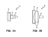
- FIG. 2A is a diagram illustrating electromechanical actuator 30 for electric boost actuation system 10.
- electromechanical actuator 30 is utilized as electric actuator 14 for system 10.
- Electromechanical actuator 30 includes base 32, motor 34, and ball screw 36. Although illustrated with motor 34 and ball screw 36, electromechanical actuator 30 may be implemented as any electrically powered electromechanical actuator. Ball screw 36 may, for example, be implemented to extend one-half the stroke length of hydraulic actuators 16. This may be done in systems in which the extra force from electromechanical actuator 30 is only needed for a first portion of the stroke of hydraulic actuators 16 under extra loading.
- Electromechanical actuator 30 may be implemented, for example, such that actuator 30 remains in base 32 for the first half-stroke of hydraulic actuators 16.
- Motor 34 receives power from power source 20 and commands from controller 18. Based upon the commands from controller 18, motor 34 translates ball screw 36 to apply force to translating ring 12 in the axial direction.
- ball screw 36 reaches its maximum extended position.
- electromechanical actuator 30 moves axially away from base 32, no longer applying force to translating ring 12.
- electromechanical actuator 30 will return to base 32, and ball screw 34 will retract.
- FIG. 2B is a diagram illustrating piezoelectric actuator 50 for electric boost actuation system 10.
- piezoelectric actuator 50 is utilized as electric actuator 14 for system 10.
- Piezoelectric actuator 50 includes base 52, piezo stack 54, springs 56, and piston 58.
- Piezo stack 54 may comprise one or more piezoelectric devices such as, for example, piezoelectric crystals. Any number of piezoelectric devices may be implemented to satisfy the needs of the specific application.
- the device When a voltage is applied across a piezoelectric device, the device may expand or compress, depending upon the polarity of the signal. This compression may be on the order of, for example, thousandths of an inch.
- Springs 56 may be implemented to amplify the reaction of the compression of piezo stack 54. For example, as piezo stack 54 compresses, springs 56 may extend outward to extend piston 58 in the axial direction. The extension of piston 58 may be configured such that it is, for example, one-half of the stroke of hydraulic actuators 16. This may be done in systems in which the extra force from piezoelectric actuators 50 is only needed for a first portion of the stroke of hydraulic actuators 16 under extra loading.
- Piezoelectric actuator 50 may be implemented, for example, such that actuator 50 remains in base 52 for the first half-stroke of hydraulic actuators 16.
- Piezo stack 54 receives a voltage from power source 20 that may be controlled based upon commands from controller 18. Based upon these commands, the voltage compresses piezo stack 54, which expands springs 56 outwardly to apply force to translating ring 12 in the axial direction through piston 58.
- piston 58 reaches its maximum extended position.
- piezoelectric actuator 50 moves axially away from base 52, no longer applying force to translating ring 12.
- piezoelectric actuator 50 will return to base 52, and piezo stack 54 will expand to its original state.
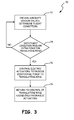
- FIG. 3 is a flowchart illustrating method 70 for actuating translating ring 12 of a gas turbine engine utilizing electric boost actuation system 10.
- controller 18 obtains sensed values from aircraft sensors 24. Controller 18 may also sample the currents provided to hydraulic actuators 16 to determine if translating ring 12 is experiencing any friction or resistance.
- controller 18 determines that the aircraft is in a high g-loading condition and/or translating ring is experiences resistance or friction, method 70 proceeds to step 76. Otherwise, method 70 returns to step 72 and continues to monitor aircraft conditions.
- controller 18 issues commands to electric actuators 14 to apply an extra force to move translating ring 12.
- controller 18 returns to controlling just hydraulic actuators 16 to control movement of translating ring 12.
- An actuation system for a gas turbine engine oriented about a centerline includes a translating ring, at least one hydraulic actuator, and at least one electric actuator.
- the translating ring is oriented about the centerline and configured to move axially along the centerline.
- the at least one hydraulic actuator is configured to provide a first mechanical force to move the translating ring along the centerline.
- the at least one electric actuator is configured to provide a second mechanical force to move the translating ring in the axial direction.
- the at least one electric actuator is controlled to provide the second mechanical force upon determination of an operating condition.
- actuation system of the preceding paragraph can optionally include, additionally and/or alternatively, any one or more of the following features, configurations and/or additional components:
- the at least one electric actuator may be an electromechanical actuator comprising a motor and a ball screw.
- the motor may be powered by a permanent magnet alternator of the gas turbine engine, and the motor translate the ball screw to apply the second mechanical force to the translating ring.
- the at least one electric actuator may have a stroke length of one-half a length of a stroke of the at least one hydraulic actuator.
- the at least one electric actuator may be a piezoelectric actuator.
- the piezoelectric actuator may include a piezo stack configured to receive a voltage from the controller, at least one spring configured to expand as the piezo stack expands or compresses in response to the voltage from the controller, and a piston configured to exert the second mechanical force on the translating ring as the at least one spring expands.
- the operating condition may be g-loading of the gas turbine engine.
- a method of actuating a translating ring of a gas turbine engine includes applying a first force, using at least one hydraulic actuator, to translate the ring in an axial direction, sampling, using a controller, at least one sensed engine condition, determining, using the controller, an operating condition of the gas turbine engine based upon the at least one sensed engine condition, and applying a second force, using at least one electric actuator, to translate the ring in the axial direction based upon the operating condition of the gas turbine engine.
- the method of the preceding paragraph can optionally include, additionally and/or alternatively, any one or more of the following features, configurations and/or additional components:
- the applying the second force, using the at least one electromechanical actuator may include powering, using a permanent magnet alternator, a motor of the electromechanical actuator; translating, using the motor, a ball screw of the electromechanical actuator; and applying the second force, using the ball screw.
- applying the second force, using the at least one electric actuator may comprise applying the second force, using at least one piezoelectric actuator, to translate the ring in the axial direction.
- applying the second force, using the at least one piezoelectric actuator may include powering, using a permanent magnet alternator, the piezoelectric actuator; controlling, using the controller, a voltage applied to a piezo stack of the piezoelectric actuator; translating a piston of the piezoelectric actuator based upon compression or expansion of the piezo stack; and applying the second force to the translating ring using the piston.
- sampling, using the engine controller, the at least one sensed engine condition may comprise monitoring current to the at least one hydraulic actuator.
- determining, using the controller, an operating condition may comprise determining, using the controller, g-loading of the gas turbine engine.
Landscapes
- Engineering & Computer Science (AREA)
- General Engineering & Computer Science (AREA)
- Mechanical Engineering (AREA)
- Chemical & Material Sciences (AREA)
- Combustion & Propulsion (AREA)
- General Electrical Machinery Utilizing Piezoelectricity, Electrostriction Or Magnetostriction (AREA)
- Transmission Devices (AREA)
Abstract
Description
- The present invention relates generally to aircraft translating rings, and in particular to electric boost actuation systems for translating rings.
- Aircraft engines, such as gas turbine engines, include translating rings that control, for example, engine nozzles. The translating ring is actuated axially along the engine's centerline in order to open/close the nozzle. This axial movement is often controlled through the use of hydraulic actuation systems. Large gas turbine engines may experience g-loading during flight that temporarily increases the translating ring's resistance to movement. This resistance to movement may create timeframes in which the existing hydraulic actuation systems are unable to provide a great enough force to actuate the translating ring. It is desirable to create a system to accommodate extra g-loading during flight without the addition of further hydraulic actuators.
- An actuation system for a gas turbine engine oriented about a centerline includes a translating ring, at least one hydraulic actuator, and at least one electric actuator. The translating ring is oriented about the centerline and configured to move axially along the centerline. The at least one hydraulic actuator is configured to provide a first mechanical force to move the translating ring along the centerline. The at least one electric actuator is configured to provide a second mechanical force to move the translating ring in the axial direction. The at least one electric actuator is controlled to provide the second mechanical force upon determination of an operating condition.
- A method of actuating a translating ring of a gas turbine engine includes applying a first force, using at least one hydraulic actuator, to translate the ring in an axial direction, sampling, using a controller, at least one sensed engine condition, determining, using the controller, an operating condition of the gas turbine engine based upon the at least one sensed engine condition, and applying a second force, using at least one electric actuator, to translate the ring in the axial direction based upon the operating condition of the gas turbine engine.
-
-
FIG. 1 is a block diagram illustrating an electric boost actuation system for actuating a translating ring of a gas turbine engine. -
FIG. 2A is a diagram illustrating an electromechanical actuator for an electric boost actuation system. -
FIG. 2B is a diagram illustrating a piezoelectric actuator for an electric boost actuation system. -
FIG. 3 is a flowchart illustrating a method for actuating a translating ring of a gas turbine engine utilizing an electric boost actuation system. - Disclosed herein is a system and method for providing electric boost actuation for translating rings of gas turbine engines. The electric boost actuation system includes a plurality of hydraulic actuators and at least one electric actuator such as, for example, an electromechanical actuator and/or a piezoelectric actuator. The electric actuator may be positioned along the ring at a position selected to have the greatest chance of binding under g-loads. The electric actuator may be powered by a permanent magnet actuator (PMA) onboard the engine using twenty-eight volt direct current (DC) or two hundred seventy volt DC power, for example. A controller may issue software commands to control the electric actuator to apply additional force as a function of, for example, g-loading, air loads on engine components, and/or hydraulic actuator position.
-
FIG. 1 is a block diagram illustrating electricboost actuation system 10 for actuating translatingring 12 of, for example, a gas turbine engine.System 10 includes translatingring 12,electric actuators 14,hydraulic actuators 16,controller 18,power source 20, nozzle 22, andaircraft sensors 24. Although illustrated as a permanent magnet alternator inFIG. 1 ,power source 20 may be implemented as any source of power forelectric actuators 14.Aircraft sensors 24 are any sensors onboard an aircraft or gas turbine engine that measure flight conditions such as air speed, altitude, and/or any other flight conditions. Gas turbine engine is oriented about a centerline (CL). - Translating
ring 12 moves axially along the centerline (CL) of the engine to adjust the area of nozzle 22. The size of the aperture of nozzle 22 is controlled based upon the axial position of translatingring 12. The size of the aperture is adjusted to control, for example, the thrust of the gas turbine engine. In past systems, for example, only hydraulic actuators were utilized to move translatingring 12 approximately four inches. The amount of force provided by these hydraulic actuators did not provide for any extra force beyond that needed to translate the ring at minimal g-loading. - During flight, if the aircraft is, for example, pulling out of a dive, the aircraft may experience significant g-loading such as four or five gravitational units. This extra loading can create increased friction and resistance to motion for translating
ring 12. Test data has shown that force augmentation of approximately one thousand pound-forces (lbfs) is sufficient for the first half of the hydraulic actuator stroke for this extra loading. For example,hydraulic actuators 16 may provide a full stroke of four inches when applying force to translatingring 16. The extra force augmentation may only be needed, for example, during the first two inches of the full four-inch stroke ofhydraulic actuators 16. Other forces may be more appropriate for other embodiments. -
Electric actuators 14 are implemented to accommodate the extra force needed to overcome the resistances and frictions created by significant g-loading during flight. Any number ofelectric actuators 14 may be implemented about translatingring 12 to provide the necessary force, such as one thousand lbfs, to translatering 12 during times of significant g-loading. The location ofelectric actuators 14 in relation to translatingring 12 may be selected based upon, for example, the most likely locations of binding alongring 12. -
Controller 18 may provide software commands to operate bothelectric actuators 14 as well ashydraulic actuators 16.Controller 18 may be, for example, an electric engine controller (EEC).Hydraulic actuators 16 may include, for example, a current drive which may be a servo motor that controls operation of the hydraulic actuator. During moments of increased resistance or friction for translatingring 12, the current to the servo motors ofhydraulic actuators 16 may increase.Controller 18 may monitor the current to the servo motors to determine if extra force fromelectric actuators 14 is needed.Controller 18 may also monitoraircraft sensors 24 to determine, for example, g-loading, air loads, or other flight conditions. Thus,electric actuators 14 may be operated bycontroller 18 only when needed based upon determination bycontroller 18. - With continued reference to
FIG. 1 ,FIG. 2A is a diagram illustratingelectromechanical actuator 30 for electricboost actuation system 10. In the embodiment illustrated inFIG. 2A ,electromechanical actuator 30 is utilized aselectric actuator 14 forsystem 10.Electromechanical actuator 30 includesbase 32,motor 34, andball screw 36. Although illustrated withmotor 34 andball screw 36,electromechanical actuator 30 may be implemented as any electrically powered electromechanical actuator.Ball screw 36 may, for example, be implemented to extend one-half the stroke length ofhydraulic actuators 16. This may be done in systems in which the extra force fromelectromechanical actuator 30 is only needed for a first portion of the stroke ofhydraulic actuators 16 under extra loading. - The end of
ball screw 36 may be connected to translatingring 12.Electromechanical actuator 30 may be implemented, for example, such thatactuator 30 remains inbase 32 for the first half-stroke ofhydraulic actuators 16.Motor 34 receives power frompower source 20 and commands fromcontroller 18. Based upon the commands fromcontroller 18,motor 34 translatesball screw 36 to apply force to translatingring 12 in the axial direction. At, for example, the first half stroke ofhydraulic actuators 16, ball screw 36 reaches its maximum extended position. Following this first half-stroke,electromechanical actuator 30 moves axially away frombase 32, no longer applying force to translatingring 12. Ashydraulic actuators 16 retract,electromechanical actuator 30 will return tobase 32, and ball screw 34 will retract. - With continued reference to
FIG. 1 ,FIG. 2B is a diagram illustratingpiezoelectric actuator 50 for electricboost actuation system 10. In the embodiment illustrated inFIG. 2B ,piezoelectric actuator 50 is utilized aselectric actuator 14 forsystem 10.Piezoelectric actuator 50 includesbase 52,piezo stack 54, springs 56, andpiston 58.Piezo stack 54 may comprise one or more piezoelectric devices such as, for example, piezoelectric crystals. Any number of piezoelectric devices may be implemented to satisfy the needs of the specific application. When a voltage is applied across a piezoelectric device, the device may expand or compress, depending upon the polarity of the signal. This compression may be on the order of, for example, thousandths of an inch.Springs 56 may be implemented to amplify the reaction of the compression ofpiezo stack 54. For example, aspiezo stack 54 compresses, springs 56 may extend outward to extendpiston 58 in the axial direction. The extension ofpiston 58 may be configured such that it is, for example, one-half of the stroke ofhydraulic actuators 16. This may be done in systems in which the extra force frompiezoelectric actuators 50 is only needed for a first portion of the stroke ofhydraulic actuators 16 under extra loading. - The end of
piston 58 may be connected to translatingring 12.Piezoelectric actuator 50 may be implemented, for example, such thatactuator 50 remains inbase 52 for the first half-stroke ofhydraulic actuators 16.Piezo stack 54 receives a voltage frompower source 20 that may be controlled based upon commands fromcontroller 18. Based upon these commands, the voltage compressespiezo stack 54, which expandssprings 56 outwardly to apply force to translatingring 12 in the axial direction throughpiston 58. At, for example, the first half stroke ofhydraulic actuators 16,piston 58 reaches its maximum extended position. Following this first half-stroke,piezoelectric actuator 50 moves axially away frombase 52, no longer applying force to translatingring 12. Ashydraulic actuators 16 retract,piezoelectric actuator 50 will return tobase 52, andpiezo stack 54 will expand to its original state. - With continued reference to
FIG. 1 ,FIG. 3 is aflowchart illustrating method 70 for actuating translatingring 12 of a gas turbine engine utilizing electricboost actuation system 10. Atstep 72,controller 18 obtains sensed values fromaircraft sensors 24.Controller 18 may also sample the currents provided tohydraulic actuators 16 to determine if translatingring 12 is experiencing any friction or resistance. Atstep 74, ifcontroller 18 determines that the aircraft is in a high g-loading condition and/or translating ring is experiences resistance or friction,method 70 proceeds to step 76. Otherwise,method 70 returns to step 72 and continues to monitor aircraft conditions. Atstep 76, upon need for movement of translatingring 12,controller 18 issues commands toelectric actuators 14 to apply an extra force to move translatingring 12. Atstep 78, following initial application of extra force fromelectric actuators 14,controller 18 returns to controlling justhydraulic actuators 16 to control movement of translatingring 12. - The following are non-exclusive descriptions of possible embodiments of the present invention.
- An actuation system for a gas turbine engine oriented about a centerline includes a translating ring, at least one hydraulic actuator, and at least one electric actuator. The translating ring is oriented about the centerline and configured to move axially along the centerline. The at least one hydraulic actuator is configured to provide a first mechanical force to move the translating ring along the centerline. The at least one electric actuator is configured to provide a second mechanical force to move the translating ring in the axial direction. The at least one electric actuator is controlled to provide the second mechanical force upon determination of an operating condition.
- The actuation system of the preceding paragraph can optionally include, additionally and/or alternatively, any one or more of the following features, configurations and/or additional components:
- In a further embodiment of the foregoing actuation system, the translating ring may be configured to adjust a nozzle of the gas turbine engine.
- In a further embodiment of any of the foregoing actuation systems, the at least one electric actuator may be an electromechanical actuator comprising a motor and a ball screw.
- In a further embodiment of any of the foregoing actuation systems, the motor may be powered by a permanent magnet alternator of the gas turbine engine, and the motor translate the ball screw to apply the second mechanical force to the translating ring.
- In a further embodiment of any of the foregoing actuation systems, the at least one electric actuator may have a stroke length of one-half a length of a stroke of the at least one hydraulic actuator.
- In a further embodiment of any of the foregoing actuation systems, the at least one electric actuator may be a piezoelectric actuator.
- In a further embodiment of any of the foregoing actuation systems, the piezoelectric actuator may include a piezo stack configured to receive a voltage from the controller, at least one spring configured to expand as the piezo stack expands or compresses in response to the voltage from the controller, and a piston configured to exert the second mechanical force on the translating ring as the at least one spring expands.
- In a further embodiment of any of the foregoing actuation systems, the operating condition may be g-loading of the gas turbine engine.
- A method of actuating a translating ring of a gas turbine engine includes applying a first force, using at least one hydraulic actuator, to translate the ring in an axial direction, sampling, using a controller, at least one sensed engine condition, determining, using the controller, an operating condition of the gas turbine engine based upon the at least one sensed engine condition, and applying a second force, using at least one electric actuator, to translate the ring in the axial direction based upon the operating condition of the gas turbine engine.
- The method of the preceding paragraph can optionally include, additionally and/or alternatively, any one or more of the following features, configurations and/or additional components:
- In a further embodiment of the foregoing method, applying the second force, using the at least one electric actuator, may comprise applying the second force, using at least one electromechanical actuator, to translate the ring in the axial direction.
- In a further embodiment of any of the foregoing methods, the applying the second force, using the at least one electromechanical actuator may include powering, using a permanent magnet alternator, a motor of the electromechanical actuator; translating, using the motor, a ball screw of the electromechanical actuator; and applying the second force, using the ball screw.
- In a further embodiment of any of the foregoing methods, applying the second force, using the at least one electric actuator, may comprise applying the second force, using at least one piezoelectric actuator, to translate the ring in the axial direction.
- In a further embodiment of any of the foregoing methods, applying the second force, using the at least one piezoelectric actuator may include powering, using a permanent magnet alternator, the piezoelectric actuator; controlling, using the controller, a voltage applied to a piezo stack of the piezoelectric actuator; translating a piston of the piezoelectric actuator based upon compression or expansion of the piezo stack; and applying the second force to the translating ring using the piston.
- In a further embodiment of any of the foregoing methods, sampling, using the engine controller, the at least one sensed engine condition may comprise monitoring current to the at least one hydraulic actuator.
- In a further embodiment of any of the foregoing methods, determining, using the controller, an operating condition may comprise determining, using the controller, g-loading of the gas turbine engine.
- While the invention has been described with reference to an exemplary embodiment(s), it will be understood by those skilled in the art that various changes may be made and equivalents may be substituted for elements thereof without departing from the scope of the invention. In addition, many modifications may be made to adapt a particular situation or material to the teachings of the invention without departing from the essential scope thereof. Therefore, it is intended that the invention not be limited to the particular embodiment(s) disclosed, but that the invention will include all embodiments falling within the scope of the appended claims.
Claims (15)
- An actuation system (10) for a gas turbine engine oriented about a centerline, the actuation system (10) comprising:a translating ring (12) oriented about the centerline (CL) and configured to move axially along the centerline (CL);at least one hydraulic actuator (16) configured to provide a first mechanical force to axially move the translating ring (12) along the centerline (CL); andat least one electric actuator (14) configured to provide a second mechanical force to axially move the translating ring (12), wherein the at least one electric actuator (14) is controlled to provide the second mechanical force upon determination of an operating condition.
- The actuation system (10) of claim 1, wherein the translating ring (12) is configured to adjust a nozzle (22) of the gas turbine engine.
- The actuation system (10) of claim 1 or 2, wherein the at least one electric actuator (14) is an electromechanical actuator (30) comprising a motor and a ball screw (36).
- The actuation system (10) of claim 3, wherein the motor (34) is powered by a permanent magnet alternator (20) of the gas turbine engine, and wherein the motor (34) translates the ball screw (36) to apply the second mechanical force to the translating ring (12).
- The actuation system (10) of any preceding claim, wherein the at least one electric actuator (14) has a stroke length of one-half a length of a stroke of the at least one hydraulic actuator (16).
- The actuation system (10) of claim 1 or 2, wherein the at least one electric actuator (14) is a piezoelectric actuator (50).
- The actuation system (10) of claim 6, wherein the piezoelectric actuator (50) comprises:a piezo stack (54) configured to receive a voltage from the controller (18);at least one spring (56) configured to expand as the piezo stack (54) expands or compresses in response to the voltage from the controller (18); anda piston (58) configured to exert the second mechanical force on the translating ring (12) as the at least one spring (56) expands.
- The actuation system (10) of any preceding claim, wherein the operating condition is g-loading of the gas turbine engine.
- A method (70) of actuating a translating ring (12) of a gas turbine engine, the method comprising:applying a first force, using at least one hydraulic actuator (16), to translate the ring (12) in an axial direction;sampling, using a controller (18), at least one sensed engine condition;determining, using the controller (18), an operating condition of the gas turbine engine based upon the at least one sensed engine condition; andapplying a second force, using at least one electric actuator (14), to translate the ring (12) in the axial direction based upon the operating condition of the gas turbine engine.
- The method (70) of claim 9, wherein applying the second force, using the at least one electric actuator (14), comprises applying the second force, using at least one electromechanical actuator (30), to translate the ring (12) in the axial direction.
- The method (70) of claim 10, wherein the applying the second force, using the at least one electromechanical actuator (30) comprises:powering, using a permanent magnet alternator (20), a motor (34) of the electromechanical actuator (30);translating, using the motor (34), a ball screw (36) of the electromechanical actuator (30); andapplying the second force, using the ball screw (36).
- The method (70) of claim 9, 10 or 11, wherein applying the second force, using the at least one electric actuator (14), comprises applying the second force, using at least one piezoelectric actuator (50), to translate the ring (12) in the axial direction.
- The method (70) of claim 12, wherein applying the second force, using the at least one piezoelectric actuator (50) comprises:powering, using a permanent magnet alternator (20), the piezoelectric actuator (50);controlling, using the controller (18), a voltage applied to a piezo stack (54) of the piezoelectric actuator (50);translating a piston (58) of the piezoelectric actuator (50) based upon compression or expansion of the piezo stack (54); andapplying the second force to the translating ring (12) using the piston (58).
- The method (70) of any of claims 9 to 13, wherein sampling, using the engine controller (18), the at least one sensed engine condition comprises monitoring current to the at least one hydraulic actuator (16).
- The method (70) of any of claims 9 to 14, wherein determining, using the controller (18), an operating condition comprises determining, using the controller (18), g-loading of the gas turbine engine.
Applications Claiming Priority (1)
| Application Number | Priority Date | Filing Date | Title |
|---|---|---|---|
| US14/503,892 US10502159B2 (en) | 2014-10-01 | 2014-10-01 | Electric boost actuation system for translating rings |
Publications (2)
| Publication Number | Publication Date |
|---|---|
| EP3002419A1 true EP3002419A1 (en) | 2016-04-06 |
| EP3002419B1 EP3002419B1 (en) | 2018-11-28 |
Family
ID=54252074
Family Applications (1)
| Application Number | Title | Priority Date | Filing Date |
|---|---|---|---|
| EP15187583.8A Active EP3002419B1 (en) | 2014-10-01 | 2015-09-30 | Gas turbine having an electric boost actuation system for translating rings and related method |
Country Status (2)
| Country | Link |
|---|---|
| US (1) | US10502159B2 (en) |
| EP (1) | EP3002419B1 (en) |
Families Citing this family (2)
| Publication number | Priority date | Publication date | Assignee | Title |
|---|---|---|---|---|
| US10040563B1 (en) * | 2013-04-11 | 2018-08-07 | Geoffrey P. Pinto | Dual panel actuator system for jet engines |
| US12025074B1 (en) * | 2023-08-14 | 2024-07-02 | Rolls-Royce North American Technologies Inc. | Plug nozzle for high mach gas turbine engines |
Citations (5)
| Publication number | Priority date | Publication date | Assignee | Title |
|---|---|---|---|---|
| WO2000005497A1 (en) * | 1998-07-22 | 2000-02-03 | General Electric Company | Vectoring nozzle calibration |
| US20040075020A1 (en) * | 2002-10-22 | 2004-04-22 | Trikha Arun K. | Method and apparatus for controlling aircraft devices with multiple actuators |
| EP2181262A2 (en) * | 2007-08-08 | 2010-05-05 | Rohr, Inc. | Variable area fan nozzle with bypass flow |
| US20100116929A1 (en) * | 2008-11-13 | 2010-05-13 | Honeywell International Inc. | Hybrid electromechanical/hydromechanical actuator and actuation control system |
| US20130312387A1 (en) * | 2012-05-22 | 2013-11-28 | Spirit Aerosystems, Inc. | Variable area fan nozzle actuation system |
Family Cites Families (3)
| Publication number | Priority date | Publication date | Assignee | Title |
|---|---|---|---|---|
| US8978356B2 (en) * | 2010-12-03 | 2015-03-17 | The Boeing Company | Thrust reverser and variable area fan nozzle actuation system and method |
| US20140145525A1 (en) * | 2012-11-28 | 2014-05-29 | Pratt & Whitney Canada Corp. | Reduced cogging torque permanent magnet machine |
| US9488130B2 (en) * | 2013-10-17 | 2016-11-08 | Honeywell International Inc. | Variable area fan nozzle systems with improved drive couplings |
-
2014
- 2014-10-01 US US14/503,892 patent/US10502159B2/en active Active
-
2015
- 2015-09-30 EP EP15187583.8A patent/EP3002419B1/en active Active
Patent Citations (5)
| Publication number | Priority date | Publication date | Assignee | Title |
|---|---|---|---|---|
| WO2000005497A1 (en) * | 1998-07-22 | 2000-02-03 | General Electric Company | Vectoring nozzle calibration |
| US20040075020A1 (en) * | 2002-10-22 | 2004-04-22 | Trikha Arun K. | Method and apparatus for controlling aircraft devices with multiple actuators |
| EP2181262A2 (en) * | 2007-08-08 | 2010-05-05 | Rohr, Inc. | Variable area fan nozzle with bypass flow |
| US20100116929A1 (en) * | 2008-11-13 | 2010-05-13 | Honeywell International Inc. | Hybrid electromechanical/hydromechanical actuator and actuation control system |
| US20130312387A1 (en) * | 2012-05-22 | 2013-11-28 | Spirit Aerosystems, Inc. | Variable area fan nozzle actuation system |
Also Published As
| Publication number | Publication date |
|---|---|
| EP3002419B1 (en) | 2018-11-28 |
| US20160097346A1 (en) | 2016-04-07 |
| US10502159B2 (en) | 2019-12-10 |
Similar Documents
| Publication | Publication Date | Title |
|---|---|---|
| EP1280029A2 (en) | Motor control system | |
| US8604741B2 (en) | Secure monitoring and control device for aircraft piloting actuator | |
| US20140286745A1 (en) | Apparatus and method for rotating fluid controlling vanes in small turbine engines and other applications | |
| ATE481317T1 (en) | MULTIMODAL MANNED AND UNMANNED VEHICLE SYSTEMS AND METHODS | |
| EP3002419B1 (en) | Gas turbine having an electric boost actuation system for translating rings and related method | |
| BRPI0511848A (en) | method for testing a combined dynamic positioning and force management system | |
| CN105035309B (en) | Actuator system for aircraft control surfaces | |
| EP2008934A3 (en) | Closed-loop cabin pressure control system test method with actual pressure feedback | |
| US7335999B2 (en) | Fluid actuated rotating device including a low power generator | |
| JP6811101B2 (en) | Electric parking brake device and brake device | |
| WO2009024688A3 (en) | System for controlling at least one actuator for thrust reverser cowlings on a turbojet engine and method for testing said system | |
| US9829055B2 (en) | Electromechanical actuator comprising a mechanical roller torque limiter | |
| GB2576099A9 (en) | Assembly for controlling variable pitch blades | |
| WO2012133066A1 (en) | Actuator monitoring system | |
| US20200148358A1 (en) | Powered dump gate system on a crop duster | |
| CN111942573B (en) | Actuator with releasable output lever | |
| KR20190044681A (en) | An apparatus for controlling an inlet guide vane through a multi-layer piezoelectric actuator | |
| CN107923372A (en) | For storing and releasing energy with the autonomous devices to power electrical apparatus | |
| CN110697028A (en) | System and method for feathering an aircraft propeller | |
| US11662001B2 (en) | Dual drive redundant load transmission device and process | |
| EP3330570B1 (en) | Control system for an actuator | |
| US20190315455A1 (en) | Electro-Mechanically Biased Supercritical Flight Control Surface Loading to Reduce High Pressure Actuation Cycles | |
| CN106989919A (en) | A kind of aircraft door fatigue experimental device | |
| US11506231B2 (en) | Multirod fluid actuator arrangement | |
| US20200266736A1 (en) | Motor control device, motor control method, motor control program, and actuator |
Legal Events
| Date | Code | Title | Description |
|---|---|---|---|
| PUAI | Public reference made under article 153(3) epc to a published international application that has entered the european phase |
Free format text: ORIGINAL CODE: 0009012 |
|
| AK | Designated contracting states |
Kind code of ref document: A1 Designated state(s): AL AT BE BG CH CY CZ DE DK EE ES FI FR GB GR HR HU IE IS IT LI LT LU LV MC MK MT NL NO PL PT RO RS SE SI SK SM TR |
|
| AX | Request for extension of the european patent |
Extension state: BA ME |
|
| 17P | Request for examination filed |
Effective date: 20161005 |
|
| RBV | Designated contracting states (corrected) |
Designated state(s): AL AT BE BG CH CY CZ DE DK EE ES FI FR GB GR HR HU IE IS IT LI LT LU LV MC MK MT NL NO PL PT RO RS SE SI SK SM TR |
|
| STAA | Information on the status of an ep patent application or granted ep patent |
Free format text: STATUS: EXAMINATION IS IN PROGRESS |
|
| 17Q | First examination report despatched |
Effective date: 20170607 |
|
| GRAP | Despatch of communication of intention to grant a patent |
Free format text: ORIGINAL CODE: EPIDOSNIGR1 |
|
| STAA | Information on the status of an ep patent application or granted ep patent |
Free format text: STATUS: GRANT OF PATENT IS INTENDED |
|
| INTG | Intention to grant announced |
Effective date: 20180614 |
|
| GRAS | Grant fee paid |
Free format text: ORIGINAL CODE: EPIDOSNIGR3 |
|
| GRAA | (expected) grant |
Free format text: ORIGINAL CODE: 0009210 |
|
| STAA | Information on the status of an ep patent application or granted ep patent |
Free format text: STATUS: THE PATENT HAS BEEN GRANTED |
|
| AK | Designated contracting states |
Kind code of ref document: B1 Designated state(s): AL AT BE BG CH CY CZ DE DK EE ES FI FR GB GR HR HU IE IS IT LI LT LU LV MC MK MT NL NO PL PT RO RS SE SI SK SM TR |
|
| REG | Reference to a national code |
Ref country code: CH Ref legal event code: EP |
|
| REG | Reference to a national code |
Ref country code: DE Ref legal event code: R096 Ref document number: 602015020311 Country of ref document: DE |
|
| REG | Reference to a national code |
Ref country code: AT Ref legal event code: REF Ref document number: 1070490 Country of ref document: AT Kind code of ref document: T Effective date: 20181215 |
|
| REG | Reference to a national code |
Ref country code: IE Ref legal event code: FG4D |
|
| REG | Reference to a national code |
Ref country code: NL Ref legal event code: MP Effective date: 20181128 |
|
| REG | Reference to a national code |
Ref country code: LT Ref legal event code: MG4D |
|
| REG | Reference to a national code |
Ref country code: AT Ref legal event code: MK05 Ref document number: 1070490 Country of ref document: AT Kind code of ref document: T Effective date: 20181128 |
|
| PG25 | Lapsed in a contracting state [announced via postgrant information from national office to epo] |
Ref country code: BG Free format text: LAPSE BECAUSE OF FAILURE TO SUBMIT A TRANSLATION OF THE DESCRIPTION OR TO PAY THE FEE WITHIN THE PRESCRIBED TIME-LIMIT Effective date: 20190228 Ref country code: FI Free format text: LAPSE BECAUSE OF FAILURE TO SUBMIT A TRANSLATION OF THE DESCRIPTION OR TO PAY THE FEE WITHIN THE PRESCRIBED TIME-LIMIT Effective date: 20181128 Ref country code: IS Free format text: LAPSE BECAUSE OF FAILURE TO SUBMIT A TRANSLATION OF THE DESCRIPTION OR TO PAY THE FEE WITHIN THE PRESCRIBED TIME-LIMIT Effective date: 20190328 Ref country code: NO Free format text: LAPSE BECAUSE OF FAILURE TO SUBMIT A TRANSLATION OF THE DESCRIPTION OR TO PAY THE FEE WITHIN THE PRESCRIBED TIME-LIMIT Effective date: 20190228 Ref country code: AT Free format text: LAPSE BECAUSE OF FAILURE TO SUBMIT A TRANSLATION OF THE DESCRIPTION OR TO PAY THE FEE WITHIN THE PRESCRIBED TIME-LIMIT Effective date: 20181128 Ref country code: LV Free format text: LAPSE BECAUSE OF FAILURE TO SUBMIT A TRANSLATION OF THE DESCRIPTION OR TO PAY THE FEE WITHIN THE PRESCRIBED TIME-LIMIT Effective date: 20181128 Ref country code: HR Free format text: LAPSE BECAUSE OF FAILURE TO SUBMIT A TRANSLATION OF THE DESCRIPTION OR TO PAY THE FEE WITHIN THE PRESCRIBED TIME-LIMIT Effective date: 20181128 Ref country code: LT Free format text: LAPSE BECAUSE OF FAILURE TO SUBMIT A TRANSLATION OF THE DESCRIPTION OR TO PAY THE FEE WITHIN THE PRESCRIBED TIME-LIMIT Effective date: 20181128 Ref country code: ES Free format text: LAPSE BECAUSE OF FAILURE TO SUBMIT A TRANSLATION OF THE DESCRIPTION OR TO PAY THE FEE WITHIN THE PRESCRIBED TIME-LIMIT Effective date: 20181128 |
|
| PG25 | Lapsed in a contracting state [announced via postgrant information from national office to epo] |
Ref country code: GR Free format text: LAPSE BECAUSE OF FAILURE TO SUBMIT A TRANSLATION OF THE DESCRIPTION OR TO PAY THE FEE WITHIN THE PRESCRIBED TIME-LIMIT Effective date: 20190301 Ref country code: PT Free format text: LAPSE BECAUSE OF FAILURE TO SUBMIT A TRANSLATION OF THE DESCRIPTION OR TO PAY THE FEE WITHIN THE PRESCRIBED TIME-LIMIT Effective date: 20190328 Ref country code: SE Free format text: LAPSE BECAUSE OF FAILURE TO SUBMIT A TRANSLATION OF THE DESCRIPTION OR TO PAY THE FEE WITHIN THE PRESCRIBED TIME-LIMIT Effective date: 20181128 Ref country code: AL Free format text: LAPSE BECAUSE OF FAILURE TO SUBMIT A TRANSLATION OF THE DESCRIPTION OR TO PAY THE FEE WITHIN THE PRESCRIBED TIME-LIMIT Effective date: 20181128 Ref country code: RS Free format text: LAPSE BECAUSE OF FAILURE TO SUBMIT A TRANSLATION OF THE DESCRIPTION OR TO PAY THE FEE WITHIN THE PRESCRIBED TIME-LIMIT Effective date: 20181128 |
|
| PG25 | Lapsed in a contracting state [announced via postgrant information from national office to epo] |
Ref country code: NL Free format text: LAPSE BECAUSE OF FAILURE TO SUBMIT A TRANSLATION OF THE DESCRIPTION OR TO PAY THE FEE WITHIN THE PRESCRIBED TIME-LIMIT Effective date: 20181128 |
|
| PG25 | Lapsed in a contracting state [announced via postgrant information from national office to epo] |
Ref country code: CZ Free format text: LAPSE BECAUSE OF FAILURE TO SUBMIT A TRANSLATION OF THE DESCRIPTION OR TO PAY THE FEE WITHIN THE PRESCRIBED TIME-LIMIT Effective date: 20181128 Ref country code: PL Free format text: LAPSE BECAUSE OF FAILURE TO SUBMIT A TRANSLATION OF THE DESCRIPTION OR TO PAY THE FEE WITHIN THE PRESCRIBED TIME-LIMIT Effective date: 20181128 Ref country code: DK Free format text: LAPSE BECAUSE OF FAILURE TO SUBMIT A TRANSLATION OF THE DESCRIPTION OR TO PAY THE FEE WITHIN THE PRESCRIBED TIME-LIMIT Effective date: 20181128 Ref country code: IT Free format text: LAPSE BECAUSE OF FAILURE TO SUBMIT A TRANSLATION OF THE DESCRIPTION OR TO PAY THE FEE WITHIN THE PRESCRIBED TIME-LIMIT Effective date: 20181128 |
|
| REG | Reference to a national code |
Ref country code: DE Ref legal event code: R097 Ref document number: 602015020311 Country of ref document: DE |
|
| PG25 | Lapsed in a contracting state [announced via postgrant information from national office to epo] |
Ref country code: EE Free format text: LAPSE BECAUSE OF FAILURE TO SUBMIT A TRANSLATION OF THE DESCRIPTION OR TO PAY THE FEE WITHIN THE PRESCRIBED TIME-LIMIT Effective date: 20181128 Ref country code: SM Free format text: LAPSE BECAUSE OF FAILURE TO SUBMIT A TRANSLATION OF THE DESCRIPTION OR TO PAY THE FEE WITHIN THE PRESCRIBED TIME-LIMIT Effective date: 20181128 Ref country code: SK Free format text: LAPSE BECAUSE OF FAILURE TO SUBMIT A TRANSLATION OF THE DESCRIPTION OR TO PAY THE FEE WITHIN THE PRESCRIBED TIME-LIMIT Effective date: 20181128 Ref country code: RO Free format text: LAPSE BECAUSE OF FAILURE TO SUBMIT A TRANSLATION OF THE DESCRIPTION OR TO PAY THE FEE WITHIN THE PRESCRIBED TIME-LIMIT Effective date: 20181128 |
|
| PLBE | No opposition filed within time limit |
Free format text: ORIGINAL CODE: 0009261 |
|
| STAA | Information on the status of an ep patent application or granted ep patent |
Free format text: STATUS: NO OPPOSITION FILED WITHIN TIME LIMIT |
|
| PG25 | Lapsed in a contracting state [announced via postgrant information from national office to epo] |
Ref country code: SI Free format text: LAPSE BECAUSE OF FAILURE TO SUBMIT A TRANSLATION OF THE DESCRIPTION OR TO PAY THE FEE WITHIN THE PRESCRIBED TIME-LIMIT Effective date: 20181128 |
|
| 26N | No opposition filed |
Effective date: 20190829 |
|
| PG25 | Lapsed in a contracting state [announced via postgrant information from national office to epo] |
Ref country code: TR Free format text: LAPSE BECAUSE OF FAILURE TO SUBMIT A TRANSLATION OF THE DESCRIPTION OR TO PAY THE FEE WITHIN THE PRESCRIBED TIME-LIMIT Effective date: 20181128 |
|
| REG | Reference to a national code |
Ref country code: DE Ref legal event code: R119 Ref document number: 602015020311 Country of ref document: DE |
|
| PG25 | Lapsed in a contracting state [announced via postgrant information from national office to epo] |
Ref country code: MC Free format text: LAPSE BECAUSE OF FAILURE TO SUBMIT A TRANSLATION OF THE DESCRIPTION OR TO PAY THE FEE WITHIN THE PRESCRIBED TIME-LIMIT Effective date: 20181128 |
|
| REG | Reference to a national code |
Ref country code: CH Ref legal event code: PL |
|
| PG25 | Lapsed in a contracting state [announced via postgrant information from national office to epo] |
Ref country code: LU Free format text: LAPSE BECAUSE OF NON-PAYMENT OF DUE FEES Effective date: 20190930 Ref country code: DE Free format text: LAPSE BECAUSE OF NON-PAYMENT OF DUE FEES Effective date: 20200401 Ref country code: CH Free format text: LAPSE BECAUSE OF NON-PAYMENT OF DUE FEES Effective date: 20190930 Ref country code: IE Free format text: LAPSE BECAUSE OF NON-PAYMENT OF DUE FEES Effective date: 20190930 Ref country code: LI Free format text: LAPSE BECAUSE OF NON-PAYMENT OF DUE FEES Effective date: 20190930 |
|
| REG | Reference to a national code |
Ref country code: BE Ref legal event code: MM Effective date: 20190930 |
|
| PG25 | Lapsed in a contracting state [announced via postgrant information from national office to epo] |
Ref country code: BE Free format text: LAPSE BECAUSE OF NON-PAYMENT OF DUE FEES Effective date: 20190930 |
|
| PG25 | Lapsed in a contracting state [announced via postgrant information from national office to epo] |
Ref country code: CY Free format text: LAPSE BECAUSE OF FAILURE TO SUBMIT A TRANSLATION OF THE DESCRIPTION OR TO PAY THE FEE WITHIN THE PRESCRIBED TIME-LIMIT Effective date: 20181128 |
|
| PG25 | Lapsed in a contracting state [announced via postgrant information from national office to epo] |
Ref country code: HU Free format text: LAPSE BECAUSE OF FAILURE TO SUBMIT A TRANSLATION OF THE DESCRIPTION OR TO PAY THE FEE WITHIN THE PRESCRIBED TIME-LIMIT; INVALID AB INITIO Effective date: 20150930 Ref country code: MT Free format text: LAPSE BECAUSE OF FAILURE TO SUBMIT A TRANSLATION OF THE DESCRIPTION OR TO PAY THE FEE WITHIN THE PRESCRIBED TIME-LIMIT Effective date: 20181128 |
|
| PG25 | Lapsed in a contracting state [announced via postgrant information from national office to epo] |
Ref country code: MK Free format text: LAPSE BECAUSE OF FAILURE TO SUBMIT A TRANSLATION OF THE DESCRIPTION OR TO PAY THE FEE WITHIN THE PRESCRIBED TIME-LIMIT Effective date: 20181128 |
|
| P01 | Opt-out of the competence of the unified patent court (upc) registered |
Effective date: 20230522 |
|
| PGFP | Annual fee paid to national office [announced via postgrant information from national office to epo] |
Ref country code: GB Payment date: 20250820 Year of fee payment: 11 |
|
| PGFP | Annual fee paid to national office [announced via postgrant information from national office to epo] |
Ref country code: FR Payment date: 20250820 Year of fee payment: 11 |