EP3002245A2 - Recognition and transmission system of the status and position of a lift cabin - Google Patents
Recognition and transmission system of the status and position of a lift cabin Download PDFInfo
- Publication number
- EP3002245A2 EP3002245A2 EP15382484.2A EP15382484A EP3002245A2 EP 3002245 A2 EP3002245 A2 EP 3002245A2 EP 15382484 A EP15382484 A EP 15382484A EP 3002245 A2 EP3002245 A2 EP 3002245A2
- Authority
- EP
- European Patent Office
- Prior art keywords
- status
- cabin
- sensor
- recognition
- transmission system
- Prior art date
- Legal status (The legal status is an assumption and is not a legal conclusion. Google has not performed a legal analysis and makes no representation as to the accuracy of the status listed.)
- Withdrawn
Links
- 230000005540 biological transmission Effects 0.000 title claims description 11
- 238000004891 communication Methods 0.000 claims abstract description 10
- 238000002604 ultrasonography Methods 0.000 claims abstract description 3
- 230000035945 sensitivity Effects 0.000 claims description 2
- 238000009434 installation Methods 0.000 abstract description 8
- 230000002452 interceptive effect Effects 0.000 abstract description 5
- 238000001514 detection method Methods 0.000 description 7
- 238000000034 method Methods 0.000 description 7
- 238000005259 measurement Methods 0.000 description 6
- 230000001133 acceleration Effects 0.000 description 5
- 238000010586 diagram Methods 0.000 description 3
- 230000008901 benefit Effects 0.000 description 2
- 238000006073 displacement reaction Methods 0.000 description 2
- 230000000284 resting effect Effects 0.000 description 2
- 239000000654 additive Substances 0.000 description 1
- 230000000712 assembly Effects 0.000 description 1
- 238000000429 assembly Methods 0.000 description 1
- 238000004364 calculation method Methods 0.000 description 1
- 230000000295 complement effect Effects 0.000 description 1
- 238000013523 data management Methods 0.000 description 1
- 238000011161 development Methods 0.000 description 1
- 230000000694 effects Effects 0.000 description 1
- 238000011156 evaluation Methods 0.000 description 1
- 230000010354 integration Effects 0.000 description 1
- 239000000463 material Substances 0.000 description 1
- 238000013439 planning Methods 0.000 description 1
- 238000012545 processing Methods 0.000 description 1
Images


Classifications
-
- B—PERFORMING OPERATIONS; TRANSPORTING
- B66—HOISTING; LIFTING; HAULING
- B66B—ELEVATORS; ESCALATORS OR MOVING WALKWAYS
- B66B1/00—Control systems of elevators in general
- B66B1/34—Details, e.g. call counting devices, data transmission from car to control system, devices giving information to the control system
- B66B1/3492—Position or motion detectors or driving means for the detector
Definitions
- An object of the present invention is a recognition and transmission system of the status and position of a lift cabin or any object in a vertical displacement with respect to points of reference.
- the present invention is characterized in that it has the means and the special functional characteristics of said means which form part of the system, so that it makes it possible to know the status of the cabin of an object such as a lift cabin, and its relative position, i.e. the floor it is on at any given time, all without interfering in the existing electromechanical system, having a simple and, consequently, economical installation.
- the present invention is included within the scope of recognition and position systems of moving objects and, more particularly, within the scope of lifting systems.
- Said magnets are read by a magnetic finger coupled to the cabin, which allows knowing its position, whilst the encoder coupled to the motor indicates if it is stopped or in movement and in what direction.
- Patent WO2014070203 discloses a method to reduce at least one error generated dynamically in terms of the real position of a lift cabin, comprising among other elements an inertial measurement unit and it uses an encoder.
- Patent EP2516305 discloses a method and a device to determine the movement and/or position of a lift cabin. It uses an IMU and an encoder in the motor.
- Patent EP2867150 discloses a measurement and load system in lifts. They make use of an accelerometer and/or a magnetometer to estimate the lift position. For this, it is necessary to first record a profile of accelerations produced on each floor, being the result of inaccuracies in the measurement.
- Patent WO2011037280 discloses a device which shows information on the floor the lift is on, also seeking to know the status and position of a moving object, in this case a cabin, but it does so with complex integration methods of the acceleration to obtain the speed and again integrating to obtain the position. The results obtained are not very reliable.
- an object of the present system is the development of a method which makes it possible to recognise the status and position of a moving object, such as, for example, a lift cabin, without interfering in any way with the electromechanical system of the object, achieving a simple, and consequently, economical installation, where it also manages to improve the precision of the measurements obtained performed by simple means, developing a system such as that described below and is essentially set down in claim one of the present application.
- An object of the present invention is a recognition and transmission system of the status and position of a lift cabin comprising:
- the sensor device may comprise a communication module, which wired and/or wirelessly transmits the information captured.
- it may complementarily have a series of remote information devices responsible for receiving and resending the signal emitted by the sensor device and the remaining remote devices as well as representing the information transmitted.
- the accelerometer of the sensor device serves for the detection of the changes in status of the cabin movement.
- a possibility of embodiment would be to use the accelerometer in combination with a gyroscope to detect movements which are not limited to an axis.
- the barometer together with the thermometer serve for reading the atmospheric pressure and temperature, being used to calculate the height which the moving object is at based on a barometric formula.
- the microcontroller/processor serves as means of control and data management as well as for resolving control algorithms.
- the communication module serves for propagation of the information referring to the cabin position and status; remote information means can be used for this.
- Power source which makes it possible to power the entire portable assembly, either independently or using a battery, or taking the power from the cabin itself.
- the remote means may be located in the most suitable places for informing the users, such as inside the cabin, or on the lift landing.
- the communication module is an optional embodiment and not necessary for the main functionality, and if it has this, the information captured can be transmitted to the remote means, housed in the cabin and/or in the lift landing, or the sensor device may even serve as means of representation of the information as it may have a screen and/or it can be connected to an additional remote screen by cable.
- the recognition process of the status and relative position of a lift cabin with the aforementioned system comprises the stages of: Establishment of a reference, in the case of a lift, the reference may be floor zero.
- the system object of the invention is the best option considered when providing a lift with new functionalities which are not of new installation.
- figure 1 we can observe a diagrammatic representation of a possible embodiment of the system.
- FIG 2 a possible detail is shown of the portable assembly which houses the sensor device, among other elements.
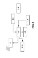
- FIG 3 a possible diagram is shown of communication between the different modules which may form the sensor device.
- FIG 1 we can observe a portable assembly (1) mounted on the roof of a cabin (2).
- the assembly portable due to the possibility it offers of being dismantled and fixed in another lifting system, always reusable and its assembly not interfering with other elements of the lift.
- the cabin (2) moves throughout the lift shaft (4) actuated by a motor (5).
- the form of fixing the portable assembly (1) does not have to be that represented, since it could be placed in any other place, with the sole necessary condition being that the device is oriented parallel to any of the three axes of the space.
- Figure 2 shows a general form of a possible embodiment of the portable assembly (1) which, as can be observed, may have:
- the portable assembly (1) is programmable through the aforementioned means and a menu of options, it being possible to program:
- FIG. 3 shows other elements which form part of the portable assembly (1) such as:
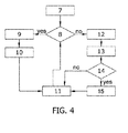
- figure 4 which shows the operating flow diagram of the sensor device, we observe it has the steps of:
Landscapes
- Engineering & Computer Science (AREA)
- Automation & Control Theory (AREA)
- Computer Networks & Wireless Communication (AREA)
- Selective Calling Equipment (AREA)
- Arrangements For Transmission Of Measured Signals (AREA)
Abstract
Description
- An object of the present invention, as the invention establishes, is a recognition and transmission system of the status and position of a lift cabin or any object in a vertical displacement with respect to points of reference.
- In terms of status recognition, it relates to the movement, resting and direction of its displacement of a lift cabin, being applicable which displaces according to a vertical movement with respect to points of reference.
- The present invention is characterized in that it has the means and the special functional characteristics of said means which form part of the system, so that it makes it possible to know the status of the cabin of an object such as a lift cabin, and its relative position, i.e. the floor it is on at any given time, all without interfering in the existing electromechanical system, having a simple and, consequently, economical installation.
- Therefore, the present invention is included within the scope of recognition and position systems of moving objects and, more particularly, within the scope of lifting systems.
- To date, the way of knowing the status and relative position of an object, particularly the cabin of a lifting system, fundamentally consists of the installation of magnets throughout the lift shaft and/or of an encoder in the motor which moves the cabin.
- Said magnets are read by a magnetic finger coupled to the cabin, which allows knowing its position, whilst the encoder coupled to the motor indicates if it is stopped or in movement and in what direction.
- Currently, new techniques are being developed such as placing QR codes instead of magnets or another type of devices both throughout the lift shaft and on each building floor. The patents we will list below are known in the state of the art and are related to recognition systems of the status and relative position of a moving object.
- Patent
WO2014070203 discloses a method to reduce at least one error generated dynamically in terms of the real position of a lift cabin, comprising among other elements an inertial measurement unit and it uses an encoder. - Patent
EP2516305 discloses a method and a device to determine the movement and/or position of a lift cabin. It uses an IMU and an encoder in the motor. - Patent
EP2867150 discloses a measurement and load system in lifts. They make use of an accelerometer and/or a magnetometer to estimate the lift position. For this, it is necessary to first record a profile of accelerations produced on each floor, being the result of inaccuracies in the measurement. - Patent
WO2011037280 discloses a device which shows information on the floor the lift is on, also seeking to know the status and position of a moving object, in this case a cabin, but it does so with complex integration methods of the acceleration to obtain the speed and again integrating to obtain the position. The results obtained are not very reliable. - In general, all the systems described have difficulties or drawbacks or aspects which can be improved, since in some case intervention in the electromechanical system is necessary, as in the case of using encoders, or they are based on complex mathematical systems which make it possible to achieve sufficient reliability and precision in the measurement.
- Therefore, an object of the present system is the development of a method which makes it possible to recognise the status and position of a moving object, such as, for example, a lift cabin, without interfering in any way with the electromechanical system of the object, achieving a simple, and consequently, economical installation, where it also manages to improve the precision of the measurements obtained performed by simple means, developing a system such as that described below and is essentially set down in claim one of the present application.
- An object of the present invention is a recognition and transmission system of the status and position of a lift cabin comprising:
- A programmable portable assembly fixed on the object from which information on its status and relative position is intended to be obtained. This sensor assembly in turn comprises:
- ∘ A sensor device comprising:
- ▪ A sensor or an array of sensors whereby we detect the changes in the movement status of the cabin, which may be an accelerometer or a magnetometer or a gyroscope or an infrared sensor, or an ultrasound sensor, working independently or any combination thereof.
- ▪ A barometer+thermometer which allows us to measure its relative height.
- ∘ Electronic means comprising a microcontroller or processor responsible for governing the operation of the remaining passive electrical / electronic elements of the sensor assembly
- ∘ Power means
- ∘ A sensor device comprising:
- Complementarily and optionally, the sensor device may comprise a communication module, which wired and/or wirelessly transmits the information captured.
- If it has a communication module, it may complementarily have a series of remote information devices responsible for receiving and resending the signal emitted by the sensor device and the remaining remote devices as well as representing the information transmitted.
- The accelerometer of the sensor device serves for the detection of the changes in status of the cabin movement. A possibility of embodiment would be to use the accelerometer in combination with a gyroscope to detect movements which are not limited to an axis.
- The barometer together with the thermometer serve for reading the atmospheric pressure and temperature, being used to calculate the height which the moving object is at based on a barometric formula.
- The microcontroller/processor serves as means of control and data management as well as for resolving control algorithms.
- The communication module, wireless or wired, serves for propagation of the information referring to the cabin position and status; remote information means can be used for this.
- Power source, which makes it possible to power the entire portable assembly, either independently or using a battery, or taking the power from the cabin itself.
- The remote means may be located in the most suitable places for informing the users, such as inside the cabin, or on the lift landing.
- As indicated above, the communication module is an optional embodiment and not necessary for the main functionality, and if it has this, the information captured can be transmitted to the remote means, housed in the cabin and/or in the lift landing, or the sensor device may even serve as means of representation of the information as it may have a screen and/or it can be connected to an additional remote screen by cable.
- The recognition process of the status and relative position of a lift cabin with the aforementioned system comprises the stages of: Establishment of a reference, in the case of a lift, the reference may be floor zero.
- Every time it is detected that the cabin starts to go up or down by means of the sensor which has been designed for this, the relative height is compared with respect to the last resting measurement by means of the barometer and thermometer unit.
- Calculation of the new position based on the initial position, basing ourselves on the calculated height variation and the distances between floors.
- Transmission of the information in wireless or wired form to the remote elements.
- To detect movement status changes, if we use the accelerometer, we could base ourselves on the typical acceleration and deceleration curves which most current lifts have, although they are not all the same and even in some models they vary as the lift system life increases, it is possible to preconfigure certain parameters which will help us to adjust the detection of said curves.
- Thanks to the system's characteristics, various effects are achieved, on the one hand:
- Possibility of installation in already existing installations without interfering or acting on the electro-mechanical means of the lifts, improving their functionality or aesthetic appearance.
- Audio-visual information to the passengers inside both the cabin and in the lift landing in some of the floors.
- Using the information provided as input for another type of more complex systems, such as those whereby the cabin aesthetics varies depending on its status and position.
- Using the information provided in benefit of the building owner (if, for example, it is a commercial building), and statistics can be prepared which facilitate the future planning or disposal of the content of each one of the floors.
- Arising from the fact that the electronic elements used and which can be included in the device are of a financial nature and with reduced dimensions, their disposal in the cabin has no consequences which affect its functionality and aesthetics.
- In consequence, the same information can be obtained which is provided by other sensors the installation of which does not obviously affect the lift system assembly, and, therefore, the system object of the invention is the best option considered when providing a lift with new functionalities which are not of new installation.
- Unless indicated otherwise, all the technical and scientific elements used in the present specification have the meaning typically understood by the normal person skilled in the art to which this invention belongs. In the practice of the present invention, it is possible to use processes or materials which are similar or equivalent to those described in the specification.
- Throughout the description and the claims the word "comprises" and its variants are not intended to exclude other technical characteristics, additives, components or steps. For persons skilled in the art, other objects, advantages and characteristics of the invention will be inferred in part from the description and in part from the practice of the invention.
- To complement the description being made and in order to aid towards a better understanding of the characteristics of the invention, in accordance with a preferred example of practical embodiment thereof, a set of drawings is attached as an integral part of said description wherein, with illustrative and non-limiting character, the following has been represented.
- In
figure 1 , we can observe a diagrammatic representation of a possible embodiment of the system. - In
figure 2 , a possible detail is shown of the portable assembly which houses the sensor device, among other elements. - In
figure 3 , a possible diagram is shown of communication between the different modules which may form the sensor device. - In
figure 4 , a possible operating flow diagram is shown of the sensor device. - In light of the figures, a preferred embodiment of the invention proposed is described below.
- In
figure 1 , we can observe a portable assembly (1) mounted on the roof of a cabin (2). We will call the assembly portable due to the possibility it offers of being dismantled and fixed in another lifting system, always reusable and its assembly not interfering with other elements of the lift. - The cabin (2) moves throughout the lift shaft (4) actuated by a motor (5). There may be remoted devices (3) both inside the cabin (2) and on the access floors to the lift which inform on the lift's position from the information generated and transmitted (6) from the portable assemblies.
- The form of fixing the portable assembly (1) does not have to be that represented, since it could be placed in any other place, with the sole necessary condition being that the device is oriented parallel to any of the three axes of the space.
-
Figure 2 shows a general form of a possible embodiment of the portable assembly (1) which, as can be observed, may have: - A series of input and output terminals (1.1)
- Programming buttons (1.2)
- A display and/or digital loudspeaker (1.3)
- Indicator LEDs (1.4),
- Therefore, the portable assembly (1) is programmable through the aforementioned means and a menu of options, it being possible to program:
- Distance between floors, which may be different for each stretch/interval
- Number of subfloors
- Reference floor
- Sensitivity of the sensor device
- Deceleration wait
- Calibration
-
Figure 3 shows other elements which form part of the portable assembly (1) such as: - The microcontroller or microprocessor (1.5) which is in connection with
- ∘ the sensor device or sensor devices (1.6) (which houses the means to detect the status and position of the moving object).
- Means of wireless (1.7), and wired (1.10) communication.
- An external power connector (1.8) or battery.
- An input (1.9) by the user
- Possible means of audio-visual information (1.3) by means of a screen and/or loudspeaker.
- In
figure 4 , which shows the operating flow diagram of the sensor device, we observe it has the steps of: - Loading of the load of the parameters (7), relative and necessary to calculate the change in the status of the movement and position of the lift from the microcontroller's memory. These parameters must be established in accordance with the lift in which the device is going to be installed and which may be introduced thanks to buttons that we have included in the device, and they can be displayed thanks to a LCD panel connected to the board.
- Detection (8) by the device if any of the buttons to access the calibration menu has been pressed by the user
- If affirmative, the screen shows (9) the calibration menu and it is possible to navigate through it and modify the different parameters using the different buttons.
- Next, the parameters (10) are saved and the available information on the cabin is later sent (11) to the remote devices wirelessly or to devices connected by cable, with the program returning to the detection stage (8) of the buttons.
- If no pressing of buttons had been detected in the detection stage (8) a reading (12) of atmospheric pressure, temperature and acceleration shall be performed if the sensor configuration was that of an independent accelerometer for status detection and barometer + thermometer for detection of the position.
- Processing (13) of data previously obtained by equations and algorithms which consider, among other elements, the acceleration curves of various types of lifts.
- Evaluating (14) if the lift is moving.
- Both if the previous evaluation is affirmative or negative, the information reached is transmitted or sent (11) to the remote devices for its representation, a sending which is performed in wireless or wired manner.
- Having sufficiently described the nature of the present invention, as well as the manner of putting it into practice, it should be stated that the layouts indicated and represented in the attached drawings are susceptible to changes of detail as long as they do not alter the main principle.
Claims (7)
- Recognition and transmission system of the status and position of a lift cabin characterized in that it comprises:- A programmable portable assembly (1) fixed on the object from which information on its status and relative position is intended to be obtained. This sensor assembly in turn comprising:∘ A sensor device (1.6) comprising:▪ A sensor or array of sensors, whereby we detect the changes in the movement status of the cabin,▪ A barometer+thermometer which allows us to measure its relative height.∘ Electronic means comprising a microcontroller or processor responsible for governing the operation of the remaining passive electrical / electronic elements of the sensor assembly∘ Power means
- Recognition and transmission system of the status and position of a lift cabin according to claim 1, wherein the system also has a wireless communication module (1.7) or wired communication module (1.10).
- Recognition and transmission system of the status and position of a lift cabin according to claim 2, wherein the system also has a series of remote information devices (3) responsible for receiving and resending the signal emitted by the sensor device and the remaining remote devices as well as representing the information transmitted.
- Recognition and transmission system of the status and position of a lift cabin, according to claim 1, wherein the sensor or array of sensors whereby the changes are detected in the status of the movement of the cabin is an accelerometer, or a magnetometer, or a gyroscope, or an infrared sensor, or an ultrasound sensor, working independently or any combination thereof.
- Recognition and transmission system of the status and position of a lift cabin, according to claim 1 or 2, wherein the portable assembly (1) has:- A series of input and output terminals (1.1)- Programming buttons (1.2)- A display and/or digital loudspeaker (1.3)- Indicator LEDs (1.4)
- Recognition and transmission system of the status and position of a lift cabin, according to any of the preceding claims wherein the programming options of the portable assembly are:- Distance between floors- Number of subfloors- Reference floor- Sensitivity of the sensor device- Deceleration wait- Calibration
- Recognition and transmission system of the status and position of a lift cabin, according to any of the preceding claims wherein the wireless communication is performed by radiofrequency or bluetooth.
Priority Applications (1)
| Application Number | Priority Date | Filing Date | Title |
|---|---|---|---|
| EP15382484.2A EP3002245A3 (en) | 2015-10-05 | 2015-10-05 | Recognition and transmission system of the status and position of a lift cabin |
Applications Claiming Priority (1)
| Application Number | Priority Date | Filing Date | Title |
|---|---|---|---|
| EP15382484.2A EP3002245A3 (en) | 2015-10-05 | 2015-10-05 | Recognition and transmission system of the status and position of a lift cabin |
Publications (2)
| Publication Number | Publication Date |
|---|---|
| EP3002245A2 true EP3002245A2 (en) | 2016-04-06 |
| EP3002245A3 EP3002245A3 (en) | 2016-04-27 |
Family
ID=54361036
Family Applications (1)
| Application Number | Title | Priority Date | Filing Date |
|---|---|---|---|
| EP15382484.2A Withdrawn EP3002245A3 (en) | 2015-10-05 | 2015-10-05 | Recognition and transmission system of the status and position of a lift cabin |
Country Status (1)
| Country | Link |
|---|---|
| EP (1) | EP3002245A3 (en) |
Cited By (9)
| Publication number | Priority date | Publication date | Assignee | Title |
|---|---|---|---|---|
| CN109789988A (en) * | 2016-10-04 | 2019-05-21 | 奥的斯电梯公司 | elevator system |
| WO2019141598A1 (en) | 2018-01-22 | 2019-07-25 | Inventio Ag | Method and device for determining a mapping of a number of floors to be served by an elevator and for determining relative trip-dependent data of an elevator cabin |
| EP3575258A1 (en) * | 2018-05-30 | 2019-12-04 | Otis Elevator Company | Wireless sensor for conveyance system monitoring |
| CN111252638A (en) * | 2018-12-03 | 2020-06-09 | 奥的斯电梯公司 | Device and method for monitoring an elevator system |
| CN111689317A (en) * | 2020-06-19 | 2020-09-22 | 揭阳市聆讯软件有限公司 | Method for automatically identifying elevator floors by system |
| CN111977477A (en) * | 2020-07-21 | 2020-11-24 | 海宁萃智智能机器人有限公司 | Elevator using sound wave for key signal wireless transmission and non-contact button thereof |
| CN112520521A (en) * | 2019-09-19 | 2021-03-19 | 奥的斯电梯公司 | Communication system for a transport system |
| CN115744520A (en) * | 2022-11-14 | 2023-03-07 | 上海思岚科技有限公司 | Method for elevator floor detection and elevator control equipment |
| EP3190075B1 (en) | 2016-12-12 | 2023-08-30 | Lift Technology GmbH | Monitoring unit for monitoring an elevator |
Citations (4)
| Publication number | Priority date | Publication date | Assignee | Title |
|---|---|---|---|---|
| WO2011037280A1 (en) | 2009-09-22 | 2011-03-31 | 노아테크놀로지(주) | Device for displaying floor information of operating elevator using acceleration sensor |
| EP2516305A1 (en) | 2009-12-22 | 2012-10-31 | Inventio AG | Method and device for determining the movement and/or the position of an elevator car |
| WO2014070203A1 (en) | 2012-11-05 | 2014-05-08 | Otis Elevator Company | Inertial measurement unit assisted elevator position calibration |
| EP2867150A1 (en) | 2012-06-27 | 2015-05-06 | KONE Corporation | Position and load measurement system for an elevator |
Family Cites Families (4)
| Publication number | Priority date | Publication date | Assignee | Title |
|---|---|---|---|---|
| DE9015495U1 (en) * | 1990-11-12 | 1992-01-02 | Technischer Überwachungs-Verein Bayern e.V., 8000 München | Transducer for recording physical parameters of a passenger and/or freight elevator |
| DE102006033605B8 (en) * | 2006-07-18 | 2008-07-10 | Fraba Ag | Device and method for determining vertical positions |
| FI20116342A7 (en) * | 2011-12-30 | 2013-07-01 | Kone Corp | Method and arrangement for determining the position and/or speed of an object adapted to move and use of the arrangement |
| KR20130123798A (en) * | 2012-05-04 | 2013-11-13 | 오인희 | Elevator floor information measuring system and overlay display device for elevator security using the same |
-
2015
- 2015-10-05 EP EP15382484.2A patent/EP3002245A3/en not_active Withdrawn
Patent Citations (4)
| Publication number | Priority date | Publication date | Assignee | Title |
|---|---|---|---|---|
| WO2011037280A1 (en) | 2009-09-22 | 2011-03-31 | 노아테크놀로지(주) | Device for displaying floor information of operating elevator using acceleration sensor |
| EP2516305A1 (en) | 2009-12-22 | 2012-10-31 | Inventio AG | Method and device for determining the movement and/or the position of an elevator car |
| EP2867150A1 (en) | 2012-06-27 | 2015-05-06 | KONE Corporation | Position and load measurement system for an elevator |
| WO2014070203A1 (en) | 2012-11-05 | 2014-05-08 | Otis Elevator Company | Inertial measurement unit assisted elevator position calibration |
Cited By (17)
| Publication number | Priority date | Publication date | Assignee | Title |
|---|---|---|---|---|
| CN109789988A (en) * | 2016-10-04 | 2019-05-21 | 奥的斯电梯公司 | elevator system |
| CN109789988B (en) * | 2016-10-04 | 2023-09-05 | 奥的斯电梯公司 | elevator system |
| EP3190075B1 (en) | 2016-12-12 | 2023-08-30 | Lift Technology GmbH | Monitoring unit for monitoring an elevator |
| CN111465567B (en) * | 2018-01-22 | 2023-07-18 | 因温特奥股份公司 | Method and apparatus for determining a map of a plurality of floors served by an elevator and for determining travel-based correlation data for an elevator car |
| WO2019141598A1 (en) | 2018-01-22 | 2019-07-25 | Inventio Ag | Method and device for determining a mapping of a number of floors to be served by an elevator and for determining relative trip-dependent data of an elevator cabin |
| CN111465567A (en) * | 2018-01-22 | 2020-07-28 | 因温特奥股份公司 | Method and apparatus for determining a map of multiple floors served by an elevator and determining trip-based related data for an elevator car |
| US12187577B2 (en) | 2018-01-22 | 2025-01-07 | Inventio Ag | Method and device for determining a mapping of a number of floors to be served by an elevator and for determining relative trip-dependent data of an elevator car |
| AU2019209249B2 (en) * | 2018-01-22 | 2021-12-02 | Inventio Ag | Method and device for determining a mapping of a number of floors to be served by an elevator and for determining relative trip-dependent data of an elevator cabin |
| EP3575258A1 (en) * | 2018-05-30 | 2019-12-04 | Otis Elevator Company | Wireless sensor for conveyance system monitoring |
| CN110550516A (en) * | 2018-05-30 | 2019-12-10 | 奥的斯电梯公司 | Wireless sensor for monitoring a transportation system |
| CN111252638A (en) * | 2018-12-03 | 2020-06-09 | 奥的斯电梯公司 | Device and method for monitoring an elevator system |
| CN111252638B (en) * | 2018-12-03 | 2022-08-23 | 奥的斯电梯公司 | Device and method for monitoring an elevator system |
| US12280987B2 (en) | 2018-12-03 | 2025-04-22 | Otis Elevator Company | Device and method for monitoring an elevator system |
| CN112520521A (en) * | 2019-09-19 | 2021-03-19 | 奥的斯电梯公司 | Communication system for a transport system |
| CN111689317A (en) * | 2020-06-19 | 2020-09-22 | 揭阳市聆讯软件有限公司 | Method for automatically identifying elevator floors by system |
| CN111977477A (en) * | 2020-07-21 | 2020-11-24 | 海宁萃智智能机器人有限公司 | Elevator using sound wave for key signal wireless transmission and non-contact button thereof |
| CN115744520A (en) * | 2022-11-14 | 2023-03-07 | 上海思岚科技有限公司 | Method for elevator floor detection and elevator control equipment |
Also Published As
| Publication number | Publication date |
|---|---|
| EP3002245A3 (en) | 2016-04-27 |
Similar Documents
| Publication | Publication Date | Title |
|---|---|---|
| US11460853B2 (en) | Apparatus, system, and method for mobile robot relocalization | |
| CN111336989B (en) | Method and apparatus for positioning using normally open barometer | |
| KR101582179B1 (en) | Calibrated hardware sensors for estimating real world distances | |
| US12202705B2 (en) | Estimation and presentation of area of interest for condition based monitoring on doors: door health heat map | |
| KR102055677B1 (en) | Mobile robot and method for controlling the same | |
| US20150185857A1 (en) | User interface method and apparatus based on spatial location recognition | |
| CN111999721B (en) | Floor recognition method, device and system and computer readable storage medium | |
| KR102837463B1 (en) | Electronic device for providing exercise information according to exercise environment | |
| JP6483556B2 (en) | Operation recognition device, operation recognition method and program | |
| EP3845479B1 (en) | Statistical analysis of elevator car location | |
| US11472666B2 (en) | Elevator maintenance app matching mechanics position with faults detected | |
| US11402525B2 (en) | Earthquake detector | |
| EP3733583B1 (en) | Elevator shaft distributed health level | |
| KR20180137915A (en) | Method for determining data of barometer sensor using data obtained from motion sensor and electronic device for the same | |
| EP3002245A3 (en) | Recognition and transmission system of the status and position of a lift cabin | |
| CN111757262B (en) | Positioning reminding method and system based on electronic fence and wearable device | |
| KR20140090071A (en) | Method for determining user exercies information and apparatus for the same | |
| EP3528477B1 (en) | Electronic apparatus, program, and control method | |
| KR102566520B1 (en) | Control and processing unit for touch screen, system including the same and method of use | |
| CN110297437B (en) | Operating table control method and device | |
| ES3016744T3 (en) | Method for controlling an elevator system using a computer-controlled mobile device | |
| KR101600561B1 (en) | Apparatus and method for indoor positioning using a smartphone | |
| CN104071661A (en) | Ranging information collection processing device and floor indication control system | |
| CN112638809A (en) | Method for controlling maintenance mode of elevator equipment and elevator control structure | |
| KR20150123022A (en) | Apparatus and method for inputting and outputting braille |
Legal Events
| Date | Code | Title | Description |
|---|---|---|---|
| PUAL | Search report despatched |
Free format text: ORIGINAL CODE: 0009013 |
|
| PUAI | Public reference made under article 153(3) epc to a published international application that has entered the european phase |
Free format text: ORIGINAL CODE: 0009012 |
|
| 17P | Request for examination filed |
Effective date: 20151102 |
|
| AK | Designated contracting states |
Kind code of ref document: A2 Designated state(s): AL AT BE BG CH CY CZ DE DK EE ES FI FR GB GR HR HU IE IS IT LI LT LU LV MC MK MT NL NO PL PT RO RS SE SI SK SM TR |
|
| AX | Request for extension of the european patent |
Extension state: BA ME |
|
| AK | Designated contracting states |
Kind code of ref document: A3 Designated state(s): AL AT BE BG CH CY CZ DE DK EE ES FI FR GB GR HR HU IE IS IT LI LT LU LV MC MK MT NL NO PL PT RO RS SE SI SK SM TR |
|
| AX | Request for extension of the european patent |
Extension state: BA ME |
|
| RIC1 | Information provided on ipc code assigned before grant |
Ipc: B66B 1/34 20060101AFI20160322BHEP |
|
| 17Q | First examination report despatched |
Effective date: 20160713 |
|
| GRAP | Despatch of communication of intention to grant a patent |
Free format text: ORIGINAL CODE: EPIDOSNIGR1 |
|
| INTG | Intention to grant announced |
Effective date: 20170428 |
|
| STAA | Information on the status of an ep patent application or granted ep patent |
Free format text: STATUS: THE APPLICATION IS DEEMED TO BE WITHDRAWN |
|
| 18D | Application deemed to be withdrawn |
Effective date: 20170909 |