EP3002191A1 - Vehicle - Google Patents
Vehicle Download PDFInfo
- Publication number
- EP3002191A1 EP3002191A1 EP15185672.1A EP15185672A EP3002191A1 EP 3002191 A1 EP3002191 A1 EP 3002191A1 EP 15185672 A EP15185672 A EP 15185672A EP 3002191 A1 EP3002191 A1 EP 3002191A1
- Authority
- EP
- European Patent Office
- Prior art keywords
- vehicle
- vehicle body
- pivot
- passenger
- actuator
- Prior art date
- Legal status (The legal status is an assumption and is not a legal conclusion. Google has not performed a legal analysis and makes no representation as to the accuracy of the status listed.)
- Granted
Links
Images







Classifications
-
- B—PERFORMING OPERATIONS; TRANSPORTING
- B62—LAND VEHICLES FOR TRAVELLING OTHERWISE THAN ON RAILS
- B62J—CYCLE SADDLES OR SEATS; AUXILIARY DEVICES OR ACCESSORIES SPECIALLY ADAPTED TO CYCLES AND NOT OTHERWISE PROVIDED FOR, e.g. ARTICLE CARRIERS OR CYCLE PROTECTORS
- B62J25/00—Foot-rests; Knee grips; Passenger hand-grips
- B62J25/06—Bar-type foot rests
-
- G—PHYSICS
- G05—CONTROLLING; REGULATING
- G05D—SYSTEMS FOR CONTROLLING OR REGULATING NON-ELECTRIC VARIABLES
- G05D3/00—Control of position or direction
Definitions
- the present invention relates to a vehicle including steps on which an occupant puts feet.
- Steps of a motorcycle are members for keeping the riding posture of a driver and a passenger and play an important role in actions such as knee grip and load shift at the time of acceleration, deceleration, and turn (refer to JP 201367182 A for example).
- step positions suitable for the traveling status can be offered, it becomes possible to facilitate a more proper riding posture, which enables more enjoyable driving and tandem traveling.
- the present invention is made in view of the above-described circumstances and an object thereof is to provide a vehicle that can induce an occupant to take a riding posture suitable for the traveling status of the vehicle.
- the present invention provides a vehicle that includes steps on which an occupant puts feet and is characterized by including a step operating mechanism that changes a step position and a control unit that changes a position of the step in response to at least any of acceleration operation, deceleration operation, and turn operation to the vehicle.
- the step operating mechanism may be a mechanism that changes height of the step for a driver, and the control unit may carry out control to raise height of the step position on an opposite side to turn direction of the vehicle.
- the step operating mechanism may be a mechanism that causes the step for a driver to pivot
- the control unit may carry out step inclining control to cause the step for a driver to pivot in order for a footrest surface of the step to become an inclined surface in which a position of vehicle body outside is raised toward a vehicle body upper side relative to a position of vehicle body inside in response to at least any of acceleration operation, deceleration operation, and turn operation to the vehicle.
- the step operating mechanism may be a mechanism that causes the passenger step on which a passenger puts a foot to pivot
- the control unit may carry out step inclining control to cause the passenger step to pivot in order for a footrest surface of the passenger step to become an inclined surface in which a position of vehicle body outside is raised toward a vehicle body upper side relative to a position of vehicle body inside in response to at least any of acceleration operation, deceleration operation, and turn operation to the vehicle.
- the control unit may determine that the vehicle is in a starting preparatory state when a clutch of the vehicle is blocking power transmission and a shift stage of the vehicle is other than neutral and carry out the step inclining control when determining that the vehicle is in the starting preparatory state, and the control unit may carry out control to move the passenger step to a neutral position at which the footrest surface is flat when determining that the vehicle is not in the starting preparatory state.
- the control unit may carry out the step inclining control when acceleration of the vehicle is positive acceleration equal to or higher than a predetermined value and when the acceleration of the vehicle is negative acceleration equal to or lower than a predetermined value, and carry out control to move the passenger step to a neutral position at which the footrest surface is flat when the acceleration of the vehicle falls within a predetermined range.
- inclination angle of the footrest surface may be changed according to any of the acceleration of the vehicle and an amount of turn in the step inclining control.
- the step operating mechanism may include a base part supported by the vehicle, a pivot part that pivotally supports the passenger step to the base part, and an actuator that causes the passenger step to pivot.
- the pivot part may support the passenger step pivotally toward a side on which at least the footrest surface becomes an inclined surface in which the position of the vehicle body outside is raised toward the vehicle body upper side relative to the position of the vehicle body inside, and the passenger step may be monolithically provided with a moved part moved by the actuator.
- the pivot part may allow the passenger step to pivot to a housing position, and the moved part may get away from a movable part of the actuator when the passenger step pivots toward the housing position.
- the movable part of the actuator may be disposed on the vehicle body inside relative to the base part.
- the moved part may extend to the vehicle body inside relative to the pivot part and the passenger step may extend from the pivot part to the vehicle body outside.
- the step operating mechanism may include a base part supported by the vehicle, a first pivot part that supports, to the base part, the passenger step pivotally toward a side on which at least the footrest surface becomes an inclined surface in which the position of the vehicle body outside is raised toward the vehicle body upper side relative to the position of the vehicle body inside, a second pivot part that supports, to the base part, the passenger step pivotally in a direction different from direction of pivot by the first pivot part, and an actuator that causes the passenger step to pivot through the first pivot part.
- the passenger step may be monolithically provided with a moved part moved by the actuator.
- the step operating mechanism may include a base part that is supported by the vehicle and pivotally supports the passenger step, a pivot part that supports the passenger step pivotally toward a side on which at least the footrest surface becomes an inclined surface in which the position of the vehicle body outside is raised toward the vehicle body upper side relative to the position of the vehicle body inside, a moved part that is pivotally supported by the base part below the base part and causes the passenger step to pivot through the pivot part, and an actuator that causes the passenger step to pivot through the moved part.
- the actuator may have a drum that winds up cables each connected to a respective one of the passenger steps on left and right sides and each of the cables may be made to pass through a lower side of the base part to be joined to the moved part.
- the step operating mechanism may include a base part that is supported by the vehicle and pivotally supports the passenger step, a pivot part that supports the passenger step pivotally toward a side on which at least the footrest surface becomes an inclined surface in which the position of the vehicle body outside is raised toward the vehicle body upper side relative to the position of the vehicle body inside, a moved part that is pivotally supported by the base part below the base part and causes the passenger step to pivot through the pivot part, and an actuator that causes the passenger step to pivot through the moved part.
- the actuator may have a drum that winds up cables each connected to a respective one of the passenger steps on left and right sides and each of the cables may be made to pass through inside of the base part in vehicle width direction to be joined to the moved part.
- the vehicle includes the step operating mechanism that changes the position of the step on which an occupant puts a foot and the control unit that changes the position of the step in response to at least any of acceleration operation, deceleration operation, and turn operation to the vehicle.
- the occupant can be induced to take a riding posture suitable for the traveling status of the vehicle.
- the step operating mechanism is a mechanism that changes the height of the step for a driver and the control unit carries out control to raise the height of the step position on the opposite side to the turn direction of the vehicle, the main step can be moved to a position to which the load to the outside at the time of the turn can be easily applied, which allows the driver to easily hold on.
- the driver can be induced to perform knee grip suitable for the traveling status of the vehicle if the step operating mechanism is a mechanism that causes the step for the driver to pivot and the control unit carries out step inclining control to cause the step for the driver to pivot in order for the footrest surface of the step to become an inclined surface in which the position of the vehicle body outside is raised toward the vehicle body upper side relative to the position of the vehicle body inside in response to at least any of acceleration operation, deceleration operation, and turn operation to the vehicle.
- the step operating mechanism is a mechanism that causes the step for the driver to pivot and the control unit carries out step inclining control to cause the step for the driver to pivot in order for the footrest surface of the step to become an inclined surface in which the position of the vehicle body outside is raised toward the vehicle body upper side relative to the position of the vehicle body inside in response to at least any of acceleration operation, deceleration operation, and turn operation to the vehicle.
- a passenger can be induced to perform knee grip suitable for the traveling status of the vehicle if the step operating mechanism is a mechanism that causes the passenger step on which the passenger puts a foot to pivot and the control unit carries out step inclining control to cause the passenger step to pivot in order for the footrest surface of the passenger step to become an inclined surface in which the position of the vehicle body outside is raised toward the vehicle body upper side relative to the position of the vehicle body inside in response to at least any of acceleration operation, deceleration operation, and turn operation to the vehicle.
- the step operating mechanism is a mechanism that causes the passenger step on which the passenger puts a foot to pivot and the control unit carries out step inclining control to cause the passenger step to pivot in order for the footrest surface of the passenger step to become an inclined surface in which the position of the vehicle body outside is raised toward the vehicle body upper side relative to the position of the vehicle body inside in response to at least any of acceleration operation, deceleration operation, and turn operation to the vehicle.
- the passenger can be induced to take a proper riding posture according to operation in association with starting preparation if the following configuration is employed. Specifically, in the case in which the vehicle speed is zero, the control unit determines that the vehicle is in the starting preparatory state when the clutch of the vehicle is blocking power transmission and the shift stage of the vehicle is other than neutral and carries out the step inclining control when determining that the vehicle is in the starting preparatory state, and the control unit carries out control to move the passenger step to the neutral position at which the footrest surface is flat when determining that the vehicle is not in the starting preparatory state.
- the control unit carries out the step inclining control when the acceleration of the vehicle is positive acceleration equal to or higher than a predetermined value and when the acceleration of the vehicle is negative acceleration equal to or lower than a predetermined value, and carries out control to move the passenger step to the neutral position at which the footrest surface is flat when the acceleration of the vehicle falls within a predetermined range.
- the step operating mechanism includes the base part supported by the vehicle, the pivot part that pivotally supports the passenger step to the base part, and the actuator that causes the passenger step to pivot. Furthermore, the pivot part supports the passenger step pivotally toward the side on which at least the footrest surface becomes an inclined surface in which the position of the vehicle body outside is raised toward the vehicle body upper side relative to the position of the vehicle body inside, and the passenger step is monolithic ally provided with the moved part moved by the actuator.
- the pivot part allows the passenger step to pivot to the housing position and the moved part gets away from the movable part of the actuator when the passenger step pivots toward the housing position, the movable part of the actuator does not hinder the movement of the passenger step to the housing position and the passenger step can be easily operated to the housing position manually.
- the movable part of the actuator can be disposed at a position hidden from the vehicle body outside if the following configuration is employed. Specifically, the movable part of the actuator is disposed on the vehicle body inside relative to the base part. Furthermore, the moved part extends to the vehicle body inside relative to the pivot part and the passenger step extends from the pivot part to the vehicle body outside.
- the passenger step can be caused to pivot also in a direction other than the direction of the step inclining control, which improves the flexibility in the pivot direction.
- the step operating mechanism includes the base part supported by the vehicle, the first pivot part that supports, to the base part, the passenger step pivotally toward the side on which at least the footrest surface becomes an inclined surface in which the position of the vehicle body outside is raised toward the vehicle body upper side relative to the position of the vehicle body inside, the second pivot part that supports, to the base part, the passenger step pivotally in a direction different from the direction of pivot by the first pivot part, and the actuator that causes the passenger step to pivot through the first pivot part.
- the passenger step is monolithically provided with the moved part moved by the actuator.
- the left and right passenger steps can be driven by one actuator and the cables and the joining parts between the cables and the moved parts can be disposed at positions that are difficult to see from the vehicle body outside.
- the step operating mechanism includes the base part that is supported by the vehicle and pivotally supports the passenger step, the pivot part that supports the passenger step pivotally toward the side on which at least the footrest surface becomes an inclined surface in which the position of the vehicle body outside is raised toward the vehicle body upper side relative to the position of the vehicle body inside, the moved part that is pivotally supported by the base part below the base part and causes the passenger step to pivot through the pivot part, and the actuator that causes the passenger step to pivot through the moved part.
- the actuator has the drum that winds up the cables each connected to a respective one of the passenger steps on the left and right sides and each of the cables is made to pass through the lower side of the base part to be joined to the moved part.
- the left and right passenger steps can be driven by one actuator and the cables and the joining parts between the cables and the moved parts can be disposed at positions that are difficult to see from the vehicle body outside.
- the step operating mechanism includes the base part that is supported by the vehicle and pivotally supports the passenger step, the pivot part that supports the passenger step pivotally toward the side on which at least the footrest surface becomes an inclined surface in which the position of the vehicle body outside is raised toward the vehicle body upper side relative to the position of the vehicle body inside, the moved part that is pivotally supported by the base part below the base part and causes the passenger step to pivot through the pivot part, and the actuator that causes the passenger step to pivot through the moved part.
- the actuator has the drum that winds up the cables each connected to a respective one of the passenger steps on the left and right sides and each of the cables is made to pass through the inside of the base part in the vehicle width direction to be joined to the moved part.
- FIG. 1 is a right side view of a motorcycle 1 according to a first embodiment of the present invention.
- This motorcycle 1 includes a vehicle body frame 2, a pair of left and right front forks 3 steerably supported by a head pipe 20 of the vehicle body frame 2, a steering handlebar 4 that is attached to the upper end parts of these front forks 3 and is disposed at the upper part of the vehicle body front part, a front wheel 5 rotatably supported by the front forks 3, and an engine 6 (power unit) supported by the vehicle body frame 2 at substantially the center of the vehicle body.
- the motorcycle 1 further includes a swingarm 7 (referred to also as rear fork) supported by the vehicle body frame 2 vertically swingably, a rear wheel 8 rotatably supported by the rear end part of this swingarm 7, a fuel tank 9 disposed at the upper part of the vehicle body frame 2, an occupant seat 10 disposed on the rear side of this fuel tank 9, and a vehicle body cowl 11 covering the vehicle body.
- a swingarm 7 (referred to also as rear fork) supported by the vehicle body frame 2 vertically swingably, a rear wheel 8 rotatably supported by the rear end part of this swingarm 7, a fuel tank 9 disposed at the upper part of the vehicle body frame 2, an occupant seat 10 disposed on the rear side of this fuel tank 9, and a vehicle body cowl 11 covering the vehicle body.
- the vehicle body frame 2 includes a pair of left and right main frames 21 extending from the head pipe 20 toward the rear lower side, a pair of left and right pivot frames 23 that are connected to the rear parts of the main frames 21 and extend downward, and a rear frame 25 extending from the upper parts of the pivot frames 23 toward the rear upper side.
- the front upper part of the engine 6 is supported by the main frames 21 and the rear part of the engine 6 is supported by the pivot frames 23. Thereby, the engine 6 is supported below the main frames 21 and in front of the pivot frames 23.
- the engine 6 is a four-cylinder engine provided with a transmission mechanism and a clutch mechanism (not shown).
- the shift stage can be changed among shift stages from first to sixth for example by the transmission mechanism according to gearshift operation by a rider (driver), and power transmission to the rear wheel 8 (drive wheel) can be blocked/connected (disconnected/connected) by the clutch mechanism according to clutch operation by the rider.
- the front end part of the swingarm 7 is pivotally supported and a pair of left and right main steps 28 (rider steps) on which the rider (driver) puts feet are supported with the intermediary of main step holders 27.
- the fuel tank 9 is supported on the main frames 21 and stores the fuel to be supplied to the engine 6.
- the occupant seat 10 is supported on the rear frame 25.
- the vehicle body cowl 11 is formed as a full cowl type covering substantially the whole of the vehicle body. It includes a front cowl 12 covering the vehicle body front part, a pair of left and right side cowls 13 that are provided consecutively with this front cowl 12 and cover the left and right sides of the vehicle body, and an under cowl 14 covering the vehicle body lower part.
- a headlight 15 is provided on the front surface of the front cowl 12.
- a windscreen (windshield) 16 is attached to the upper part of the front cowl 12.
- Left and right mirrors 17 are attached to the left and right sides of the front cowl 12.
- This motorcycle 1 includes, as other cover members, a front fender 18 covering the upper side of the front wheel 5 and a rear fender 19 covering the upper side of the rear wheel 8.
- symbol 31 denotes an exhaust muffler that is disposed on the right side of the rear wheel 8 and emits an exhaust gas of the engine 6.
- This motorcycle 1 is formed as a two-seater vehicle a rider and a passenger (fellow passenger) can ride.
- the occupant seat 10 is formed as a seat having a front seat 41 (rider riding part) on which the rider sits and a rear seat 42 (passenger riding part) on which the passenger sits as front and rear parts thereof.
- a pair of left and right pillion steps 81 (passenger steps) on which the passenger puts feet are pivotally supported with the intermediary of a step operating mechanism 82.
- knee grip In tandem traveling, the passenger often moves to a large extent due to acceleration, deceleration, or turn according to operation by the rider. As one of riding techniques of the passenger, there is a state in which the passenger lightly clamps the waist part of the rider by both knees (hereinafter, referred to as knee grip).
- the riding posture of the passenger also affects the driving of the vehicle. Therefore, the rider can enjoy the tandem traveling more if the motion of the passenger can be properly suppressed.
- the step operating mechanism 82 that can induce the passenger to perform knee grip according to the traveling status of the vehicle is provided and control of the step operating mechanism 82 is carried out.
- the left and right pillion steps 81 and step operating mechanisms 82 are symmetrical between the left and right sides. In the following, one of the pillion steps 81 and one of the step operating mechanisms 82 will be described.
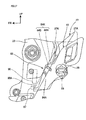
- FIG. 2 is a perspective view showing the left pillion step 81 with the step operating mechanism 82 and FIG. 3 is a diagram obtained when FIG. 2 is viewed from the vehicle body left side.
- the step operating mechanism 82 monolithically includes a base part 83 supported by the rear frame 25 and a pivot part 84 that extends from the base part 83 toward the outside in the vehicle width direction and pivotally supports the pillion step 81 with the intermediary of a pivot shaft 84A.
- the base part 83 is composed of a metal material such as an aluminum alloy and is formed into a triangular frame shape in side view.
- the base part 83 pivotally supports the pillion step 81 with the intermediary of the pivot part 84 at the corner part at the lowermost position in the triangle.
- the base part 83 is formed into a frame shape extending downward, rearward, and so forth from the vehicle body frame 2 (rear frame 25, in the present embodiment) toward the position that is the most suitable for the passenger to put a foot on.
- plural through-holes 83A are formed at intervals in a region corresponding to the top side of the triangle and the base part 83 is fixed to the rear frame 25 by fastening members (not shown) through these through-holes 83A.
- the pivot part 84 is formed as a pivotal support part that supports the pillion step 81 pivotally to at least a neutral position at which a footrest surface 81A of the pillion step 81 is set to a horizontal surface extending outward in the vehicle width direction when the vehicle body stands uptight (see FIG. 2 ) and an inclined position at which the footrest surface 81A is set to an inclined surface in which the position of the vehicle body outside is raised toward the vehicle body upper side relative to the position of the vehicle body inside when the vehicle body stands uptight.
- the pillion step 81 has a step part 85 that is pivotally supported by the pivot part 84 with the intermediary of the pivot shaft 84A and extends outward in the vehicle width direction at the neutral position and the inclined position, and includes a footrest part 86 forming the footrest surface 81A on which the passenger puts a foot at the upper part of this step part 85 monolithically or as a separate body.
- a base end part 81K (equivalent to the inside end part in the vehicle width direction) of this step part 85, an arm part 87 (moved part) extending toward the vehicle body inside at the neutral position and the inclined position is monolithically provided.
- the neutral position at which the footrest surface 81A is set to a horizontal surface
- the passenger can easily step foot on the footrest surface 81A when riding or getting down the motorcycle 1 and it is also possible to sufficiently ensure easiness of riding and alighting.
- This neutral position is equivalent to the use position when the passenger rides the vehicle in conventional motorcycles.
- the neutral position of the present embodiment is equivalent to a horizontal position at which the footrest surface 81A of the pillion step 81 is set to a horizontal surface.
- the neutral position may be a position at which the footrest surface 81A is set to a slightly-inclined surface.
- the pivot shaft 84A which defines the pivot axis line of the pillion step 81, is supported with such a posture as to be along the vehicle body front-rear direction and be slightly inclined to have the lowered rear part. Because the pivot shaft 84A is along the vehicle body front-rear direction, when the pillion step 81 pivots upward from the neutral position shown by a solid line in FIG. 3 on the basis of the pivot shaft 84A, the footrest surface 81A becomes an inclined surface in which the position of the vehicle body outside is raised toward the vehicle body upper side relative to the position of the vehicle body inside. Furthermore, the inclination angle thereof can be arbitrarily changed by changing the amount of pivot (pivot angle).
- the footrest surface 81A of the pillion step 81 substantially abuts against the base part 83 and the further pivot of the pillion step 81 is restricted.
- This position is equivalent to a housing position at which the whole of the pillion step 81 is close to the base part 83 and is folded to the inside in the vehicle width direction. That is, when the pillion step 81 is not used, setting the pillion step 81 at this housing position can suppress the extension of the pillion step 81 toward the outside in the vehicle width direction. Furthermore, this pillion step 81 can be made to pivot and move to the housing position by an occupant manually. In FIG. 3 , the pillion step 81 at the housing position is shown by a two-dot chain line.
- the pillion step 81 pivots along a straight line that is orthogonal to this pivot shaft 84A and extends toward the rear upper side when being viewed from the vehicle body lateral side.
- the pillion step 81 can be disposed along the rear edge part of the base part 83 extending toward the rear upper side and is allowed to have appearance integrated with the base part 83.
- the step operating mechanism 82 includes an actuator 90 that causes the pillion step 81 to pivot.
- This actuator 90 is a linear actuator having a movable part 90A that can linearly move. As shown in FIGS. 2 and 3 , the actuator 90 is attached on the vehicle body inside of the base part 83 along the rear edge of the base part 83 and is disposed to allow the movable part 90A to advance downward and retreat.
- FIG. 4 shows diagrams depicting the posture change of the pillion step 81 by the actuator 90.
- FIG. 4(A) shows a state with the neutral position.
- FIG. 4(B) shows a state with a first inclination angle ⁇ A.
- FIG. 4(C) shows a state with a second inclination angle ⁇ B ( ⁇ B > ⁇ A).
- the movable part 90A of the actuator 90 can set the pillion step 81 at each of the neutral position (see FIG. 4(A) ), the first inclination angle ⁇ A (see FIG. 4(B) ), and the second inclination angle ⁇ B (see FIG. 4(C) ) by abutting against the upper surface of the arm part 87 of the pillion step 81 and pressing the arm part 87 downward.
- the first and second inclination angles ⁇ A and ⁇ B are angles at which the footrest surface 81A is an inclined surface in which the position of the vehicle body outside is raised toward the vehicle body upper side relative to the position of the vehicle body inside when being viewed with the posture when the vehicle body stands upright.
- the first and second inclination angles ⁇ A and ⁇ B are rotation angles from the neutral position based on the pivot axis and satisfy a relationship of 90° (angle of the housing position) > second inclination angle ⁇ B > first inclination angle ⁇ A.
- the second inclination angle ⁇ B is 20° and the first inclination angle ⁇ A is 10°.
- Step inclining control may be employed in which a force to cause the pillion step 81 to pivot is so generated that the force to incline the pillion step 81 becomes larger depending on the difference between a target value according to the acceleration and the present position.
- symbol Ft denotes a foot of a passenger put on the pillion step 81 and symbol Lf denotes the center axis line of the region from the foot Ft to a knee.
- the footrest surface 81A As shown in FIG. 4(A) , at the neutral position, the footrest surface 81A is horizontal and therefore the region Lf from the foot Ft put on the footrest surface 81A to the knee stands substantially vertically. In contrast, at the first inclination angle ⁇ A, the footrest surface 81A becomes the above-described inclined surface.
- the region Lf from the foot Ft to the knee is so inclined that its part at a higher level is closer to the inside in the vehicle width direction. That is, the passenger can be induced to a knee grip state in which the passenger clamps the waist part of the rider by the knees.
- the inclination angle is larger than the first inclination angle ⁇ A. Therefore, the knee can be guided to the inside in the vehicle width direction to a larger extent and it becomes possible to induce the knee grip more or induce somewhat stronger knee grip.
- the first inclination angle ⁇ A and the second inclination angle ⁇ B may be set to angles suitable for the knee grip as appropriate.
- FIG. 5 is a diagram showing the internal structure of the actuator 90.
- the actuator 90 is a linear motion mechanism that linearly moves the movable part 90A by using a motor 91 and a ball screw 92.
- the actuator 90 has a structure in which the motor 91 whose rotation is controlled by an ECU 100 to be described later and the ball screw 92 joined to the rotating shaft of the motor 91 are housed in a cylindrical actuator case 93 whose lower end is opened and the movable part 90A is screwed to this ball screw 92.
- the movable part 90A can move in the axial direction of the ball screw 92 by being guided by the inner surface of the actuator case 93 and is so provided as to be incapable of moving in the rotation direction of the ball screw 92.
- the movable part 90A to advance and retreat in the axial direction of the ball screw 92 according to the rotation of the motor 91.
- the pillion step 81 can be moved to each of the neutral position, the position of the first inclination angle ⁇ A, and the position of the second inclination angle ⁇ B shown in FIGS. 4(A) to 4(C) .
- FIG. 6 shows a modification example of the actuator 90.
- the actuator 90 shown in FIG. 6 is a so-called hydraulic cylinder and includes an actuator case 93 configuring a cylinder part forming a hydraulic chamber, the movable part 90A functioning as a piston slidable relative to the actuator case 93, and a biasing member 94 that biases the movable part 90A toward the retraction side. Furthermore, the actuator 90 includes a pump 95 that supplies a hydraulic pressure to the hydraulic chamber of the actuator case 93. Under this configuration, the pump 95 is driven by the ECU 100 to be described later. Thereby, a hydraulic pressure is supplied into the actuator case 93 via a hose 96 and the movable part 90A moves according to this hydraulic pressure against the biasing force of the biasing member 94. This can cause the pillion step 81 to pivot.
- the actuator 90 may be one having a mechanism other than the ball screw mechanism and the hydraulic cylinder and a publicly-known actuator can be widely applied.
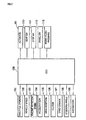
- FIG. 7 is a block diagram showing the ECU (electronic control unit) 100, which controls the actuators 90, with the peripheral configuration.
- the ECU 100 is an electrical component unit composed of a computer and various kinds of electronic components and functions as a control unit that controls the respective parts of the vehicle body including the actuators 90.
- a throttle opening sensor 101 that detect the degree of opening of a throttle operated by a rider (throttle opening); a vehicle speed sensor 102 that detects the vehicle speed; an Ne sensor 103 that detects the engine rotation speed; an acceleration sensor 104 that detects the acceleration; a gear position sensor 105 that detects the present shift stage; a clutch detecting switch 106 that detects ON (power transmission is blocked)/OFF (power is transmitted) of the clutch mechanism; a gyro sensor 107 (tilt angle sensor) for detecting the tilt of the vehicle body (roll angle) and so forth; a steering angle sensor 108 that detects the steering angle of the front wheel 5 (or handlebar 4); a navigation device 109; a seat switch 110 that detects whether or not a passenger sits on the rear seat 42; a step switch 111 that detect
- the navigation device 109 is a device that includes a GPS (global positioning system) unit and has a map display function of displaying map information of a surrounding area including the present location on the basis of the present location acquired by the GPS unit, a route guide function of performing a route guide from the present location to a destination set in advance, and so forth.
- GPS global positioning system
- the map information used by the navigation device 109 generally includes road information including nodes and links indicating a road network.
- navigation devices having the following functions have come to appearance: a function of detecting, in advance, traveling information on whether or not the road on the traveling forward side curves and so forth by using this road information; and a function of detecting, in advance, whether or not the traveling forward side is in a situation involving change in the vehicle body behavior (e.g. the existence of sharp curve, temporary stop site, and railroad crossing) on the basis of additional information added in advance.
- the navigation device 109 of the present embodiment has a function of detecting whether or not the traveling forward side is in a situation involving change in the vehicle body behavior in advance and notifying the ECU 100 of the detected information.
- the brake fluid pressure detecting sensor 113 detects whether or not the brake is being actuated on the basis of the brake fluid pressure, i.e. whether or not the brake is being operated. Therefore, by using the results of both the brake switch 112 and the brake fluid pressure detecting sensor 113, the accuracy of the detection of whether or not the brake is being operated is enhanced compared with the case of using only the result of either one.
- FIG. 7 shows part of the configurations connected to the ECU 100.
- the ECU 100 carries out engine control (intake control and ignition control) and so forth.
- an ON/OFF function based on a manual switch may be provided so that the step inclining control may be prevented.
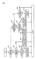
- FIG. 8 is a flowchart showing the control of the pillion steps 81. This flowchart shows processing executed when the ECU 100 has determined that a passenger is currently riding the motorcycle 1 on the basis of a detection result of the seat switch 110. However, if the seat switch 110 is not provided, this processing may be repeatedly executed at a predetermined interrupt cycle.
- a step S1A the ECU 100 determines whether or not the vehicle speed is zero on the basis of a detection result of the vehicle speed sensor 102. If the vehicle speed is zero, the ECU 100 executes processing of determination of whether or not the motorcycle 1 is in a starting preparatory state (step S2A). In this step S2A, the ECU 100 determines whether or not a predetermined condition with which the motorcycle 1 can be determined to be in the starting preparatory state is satisfied.
- the ECU 100 determines that the motorcycle 1 is in the starting preparatory state if the clutch is ON (power transmission is blocked) and the shift stage is other than neutral and the brake is being operated.
- the ECU 100 determines whether or not the pillion steps 81 are at the neutral position on the basis of a detection result of the step switch 111 (step S3A). If the pillion steps 81 are not at the neutral position, the ECU 100 carries out return control in which the actuators 90 are driven to return the pillion steps 81 to the neutral position (step S4A). In this return control, control to return the pillion steps 81 to the neutral position while smoothly changing the angular velocity of the pillion steps 81 so that the passenger may be prevented from being given a sense of discomfort is carried out. For example, velocity control by which the angular velocity changes in a sinusoidal manner is carried out. On the other hand, if the pillion steps 81 are at the neutral position, the ECU 100 temporarily ends this processing and thereafter executes the processing of the step S1A.
- step S5A the ECU 100 carries out first step raising control (step S5A).
- This first step raising control is step inclining control in which the actuators 90 are driven to incline the pillion steps 81 to the first inclination angle ⁇ A.
- the pillion steps 81 are made to pivot to the first inclination angle ⁇ A in a stepwise manner. Inclining the pillion steps 81 to the first inclination angle ⁇ A can induce the passenger who puts feet on the pillion steps 81 to perform knee grip and induce the passenger to take a riding posture suitable for behavior change.
- the pillion steps 81 to pivot in a stepwise manner, the movement of the pillion steps 81 can be clearly conveyed to the passenger and the passenger can be urged to pay attention to starting.
- step S6A determines whether or not the motorcycle 1 is in a state of change in the vehicle body behavior.
- the "state of change in the vehicle body behavior" in the step S6A includes both a “state in which change in the vehicle body behavior is anticipated" and “vehicle body behavior is currently changing.” If determining that the motorcycle 1 is in the "state of change in the vehicle body behavior," the ECU 100 makes transition to a step S7A and determines whether or not the motorcycle 1 is in the "state in which change in the vehicle body behavior is anticipated.”
- the change in the vehicle body behavior can be determined by using any of the throttle opening, change in the vehicle speed or the engine rotation speed, the acceleration, the tilt of the vehicle body (roll angle), the roll rate (the amount of change in the roll angle per predetermined time), the steering angle of the front wheel 5, the status of brake control, and specific information from the navigation device 109 (information or notification indicating that the traveling forward side is in a situation involving change in the vehicle body behavior, specifically e.g. information or notification indicating the existence of sharp curve, temporary stop site, and railroad crossing).
- information or notification indicating that the traveling forward side is in a situation involving change in the vehicle body behavior specifically e.g. information or notification indicating the existence of sharp curve, temporary stop site, and railroad crossing.
- the ECU 100 in order to determine whether or not the motorcycle 1 is in the "state in which change in the vehicle body behavior is anticipated," the ECU 100 detects whether or not acceleration operation by the rider is carried out through the throttle opening sensor 101 and detects whether or not brake operation by the rider is carried out through the brake switch 112. Furthermore, the ECU 100 detects whether or not shift-down operation by the rider is carried out through the gear position sensor 105 and detects whether or not specific information from the navigation device 109 (e.g. information or notification indicating the existence of sharp curve, temporary stop site, and railroad crossing) is received.
- specific information from the navigation device 109 e.g. information or notification indicating the existence of sharp curve, temporary stop site, and railroad crossing
- the ECU 100 detects whether or not any of acceleration operation, deceleration operation, and turn operation is carried out or whether or not specific information is received from the navigation device 109. When detecting any kind of operation or information, the ECU 100 determines that the motorcycle 1 is in the "state in which change in the vehicle body behavior is anticipated.”
- the ECU 100 executes the following processing.
- the ECU 100 determines whether the motorcycle 1 is accelerating (speed is increasing) or decelerating (speed is decreasing) on the basis of the acceleration detected by the acceleration sensor 104. At the time of acceleration, the ECU 100 carries out acceleration correction in which the acceleration generated after a minute time is estimated from the accelerator opening and the engine rotation speed. At the time of deceleration, the ECU 100 carries out deceleration correction in which the negative acceleration (deceleration) generated after a minute time is estimated on the basis of at least any of the brake switch 112, the brake fluid pressure, the accelerator opening, and the engine rotation speed. The ECU 100 employs the acceleration or deceleration after the correction as a determination value of the vehicle body behavior.
- the ECU 100 determines that "the vehicle body behavior is currently changing" if the determination value surpasses a predefined threshold that is a determination reference value of change in the vehicle body behavior, i.e. if the acceleration or deceleration after the minute time is equal to or higher than a predetermined value.
- the ECU 100 detects the roll angle of the vehicle body and the roll rate through the gyro sensor 107 and detects change in the steering angle through the steering angle sensor 108. Then, on the basis of them, the ECU 100 obtains a determination value of behavior change in the turn direction. The ECU 100 determines that "the vehicle body behavior is currently changing” if this determination value surpasses a predefined threshold that is a determination reference value of change in the vehicle body behavior, i.e. also in the case of a turn equal to or larger than a predetermined turn. In this manner, whether or not "the vehicle body behavior is currently changing" can be accurately determined.
- the acceleration changes depending on the magnitude of the traveling resistance.
- characteristic data of the traveling resistance is held in advance and the traveling resistance is identified in advance on the basis of the immediately-previous accelerator opening, the engine rotation speed, vehicle speed change, and so forth.
- the acceleration is obtained from the excess driving force in consideration of the characteristic data of this identified traveling resistance.
- the characteristic data of the traveling resistance data made by describing characteristics of the traveling resistance, the engine rotation speed, the accelerator opening, and the acceleration when the driving force is indicated on the ordinate and the speed is indicated on the abscissa is stored, and the acceleration can be obtained on the basis of this data.
- step S8A if determining that the motorcycle 1 is in the "state in which change in the vehicle body behavior is anticipated," the ECU 100 carries out the first step raising control (step S8A). If determining that "the vehicle body behavior is currently changing,” the ECU 100 carries out second step raising control (step S9A).
- This second step raising control is control of keeping on driving the actuators 90 toward the larger side of the inclination angle of the pillion steps 81 to keep on applying a force to the passenger.
- the maximum value of the inclination angle of the pillion steps 81 in this case is set to the second inclination angle ⁇ B and excessive inclination of the pillion steps 81 is suppressed. This can induce knee grip to a larger extent and induce the passenger to take a riding posture suitable for the behavior change.
- the ECU 100 determines whether or not the pillion steps 81 are at the neutral position on the basis of a detection result of the step switch 111 (step S 10A). If the pillion steps 81 are not at the neutral position, the ECU 100 carries out the return control in which the actuators 90 are driven to return the pillion steps 81 to the neutral position (step S11A). Also in this return control, control to return the pillion steps 81 to the neutral position while smoothly changing the angular velocity of the pillion steps 81 so that the passenger may be prevented from being given a sense of discomfort, specifically e.g. velocity control by which the angular velocity changes in a sinusoidal manner, is carried out.
- the ECU 100 temporarily ends this processing and thereafter executes the processing of the step S1A.
- the above is the control of the pillion steps 81.
- the motorcycle 1 includes the step operating mechanisms 82 that change the positions of the pillion steps 81. Furthermore, in response to at least any of acceleration operation, deceleration operation, and turn operation to the motorcycle 1, the ECU 100 carries out the step inclining control to change the positions of the pillion steps 81 (passenger steps) in such a manner that the footrest surfaces 81A of the pillion steps 81 each become an inclined surface in which the position of the vehicle body outside is raised toward the vehicle body upper side relative to the position of the vehicle body inside. Therefore, the passenger can be induced to perform knee grip according to the behavior of the motorcycle 1 and be informed of behavior change of the motorcycle 1. This can induce the passenger to take a proper riding posture suitable for the traveling status of the motorcycle 1, which facilitates the driving by the rider. Consequently, more enjoyable driving and tandem traveling are enabled.
- the ECU 100 determines that the motorcycle 1 is in the starting preparatory state when the clutch mechanism possessed by the motorcycle 1 is in the state of blocking power transmission and the shift stage of the motorcycle 1 is other than neutral.
- the ECU 100 carries out the step inclining control.
- the ECU 100 carries out the return control to move the pillion steps 81 to the neutral position, at which the footrest surface 81A is flat. This can induce the passenger to take a proper riding posture suitable for starting preparation.
- the ECU 100 carries out the step inclining control when the acceleration of the motorcycle 1 is positive acceleration equal to or higher than a predetermined value and when the acceleration is negative acceleration equal to or lower than a predetermined value.
- the ECU 100 carries out the return control to move the pillion steps 81 to the neutral position, at which the footrest surface 81A is flat.
- the ECU 100 determines whether or not the motorcycle 1 is in the "state in which change in the vehicle body behavior is anticipated" and determines whether or not "the vehicle body behavior is currently changing.” Furthermore, the ECU 100 makes the step inclining control different according to the respective states. Thus, the passenger can be induced to take a proper riding posture according to the respective states. In addition, the ECU 100 carries out control to incline the pillion steps 81 to the first inclination angle ⁇ A in a stepwise manner if change in the vehicle body behavior is anticipated, and carries out control to incline the pillion steps 81 beyond the first inclination angle ⁇ A if the vehicle body behavior is currently changing. Thus, the passenger can be urged to pay attention to future behavior change if change in the vehicle body behavior is anticipated. In addition, knee grip can be induced to a larger extent if the vehicle body behavior is currently changing.
- the acceleration generated after a minute time is estimated from the accelerator opening and the engine rotation speed at the time of acceleration.
- the pillion steps 81 can be properly controlled according to change in the vehicle body behavior due to the acceleration.
- the negative acceleration (deceleration) generated after a minute time is estimated on the basis of at least any of the brake switch 112, the brake fluid pressure, the accelerator opening, and the engine rotation speed at the time of deceleration.
- the pillion steps 81 can be properly controlled according to change in the vehicle body behavior due to the deceleration.
- the step operating mechanism 82 includes the base part 83 supported by the motorcycle 1, the pivot part 84 that pivotally supports the pillion step 81 to the base part 83, and the actuator 90 that causes the pillion step 81 to pivot.
- the pivot part 84 supports the pillion step 81 pivotally toward the side on which at least the footrest surface 81A becomes an inclined surface in which the position of the vehicle body outside is raised toward the vehicle body upper side relative to the position of the vehicle body inside.
- the arm part 87 (moved part) moved by the movable part 90A of the actuator 90 is monolithically provided.
- the pivot part 84 can cause the pillion step 81 to pivot to the housing position, and the arm part 87 of the pillion step 81 gets away from the movable part 90A of the actuator 90 when the pillion step 81 is caused to pivot toward the housing position. Therefore, the movable part 90A of the actuator 90 does not hinder the movement of the pillion step 81 to the housing position and the pillion step 81 can be easily operated to the housing position manually.
- the movable part 90A of the actuator 90 is disposed on the vehicle body inside relative to the base part 83 and the arm part 87 extends to the vehicle body inside relative to the pivot part 84.
- the pillion step 81 extends from the pivot part 84 to the vehicle body outside.
- the movable part 90A of the actuator 90 can be disposed at a position hidden from the vehicle body outside.
- the structure to cause the pillion step 81 to pivot by the actuator 90 can be simply configured by the arm part 87 extending inward relative to the pivot part 84 and the pillion step 81 extending from the pivot part 84 to the vehicle body outside.
- the actuator 90 is disposed on the vehicle body inside of the base part 83. Thus, the actuator 90 can be disposed at a position that is difficult to see from the vehicle body outside.
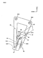
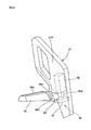
- FIG. 9 is a perspective view showing a pillion step 81 of a second embodiment with a step operating mechanism 82.
- FIG. 10 is a side view as viewed from the vehicle body left side.
- the second embodiment is different from the first embodiment in that the step operating mechanism 82 includes, in addition to the above-described pivot part 84 (hereinafter, referred to as the first pivot part), a second pivot part 89 that supports the pillion step 81 pivotally in a direction different from the direction of the pivot by the first pivot part 84.
- the step operating mechanism 82 includes, in addition to the above-described pivot part 84 (hereinafter, referred to as the first pivot part), a second pivot part 89 that supports the pillion step 81 pivotally in a direction different from the direction of the pivot by the first pivot part 84.
- Members corresponding to the respective members in the first embodiment are shown with the same symbols and different points will be described.
- the second pivot part 89 is provided monolithic ally with a support part 89B pivotally supported by the first pivot part 84 and pivotally supports the base end part of a step part 85. Furthermore, an arm part 87 (moved part) extending toward the vehicle body inside when the pillion step 81 is at the neutral position or an inclined position is provided monolithically with this support part 89B.
- the second pivot part 89 is formed as a pivotal support part that supports the pillion step 81 pivotally substantially along the nearly front-rear direction of the motorcycle 1. Specifically, as shown in FIG. 10 , a pivot shaft 89A of the second pivot part 89 is inclined to have the lowered rear part at a steeper angle than a pivot shaft 84A of the first pivot part 84 in the vehicle body side view, and the pillion step 81 can pivot rearward on the basis of this pivot shaft 89A. Through the rearward pivot, the pillion step 81 abuts against a base part 83 and can be manually operated to a housing position shown by a two-dot chain line in FIG. 10 .
- An actuator 90 is attached on the vehicle body inside of the base part 83 along the front edge of the base part 83 and is disposed to allow a movable part 90A to advance downward and retreat.
- This movable part 90A abuts against the upper surface of the arm part 87 and presses the arm part 87 downward.
- This can set the pillion step 81 at the above-described neutral position and positions of the first inclination angle ⁇ A and the second inclination angle ⁇ B through the first pivot part 84.
- the pillion step 81 can be so supported as to be capable of pivoting by the actuator 90 toward the side on which at least a footrest surface 81A becomes an inclined surface in which the position of the vehicle body outside is raised toward the vehicle body upper side relative to the position of the vehicle body inside. Therefore, the same control of the pillion steps 81 as the first embodiment can be applied and various kinds of effects such as the effect that the passenger can be induced to perform knee grip according to the traveling status of the motorcycle 1 can be achieved as with the first embodiment.
- the step operating mechanism 82 includes, in addition to the first pivot part 84, the second pivot part 89 supporting, to the base part 83, the pillion step 81 pivotally in a direction different from the direction of the pivot by the first pivot part 84. Therefore, the pillion step 81 can be caused to pivot also in a direction other than the direction of the step inclining control, which improves the flexibility in the pivot direction. Due to this, the pivot direction when the step is housed can be arbitrarily set. Thus, even when a vehicle body constitutional component exists around the pillion step 81, the pillion step 81 can housed with avoidance of this component.
- the second pivot part 89 supports the pillion step 81 pivotally substantially along the nearly front-rear direction of the motorcycle 1. Therefore, in the case in which a vehicle body constitutional component exists in the vicinity of the upper side of the pillion step 81 and it is difficult to move the pillion step 81 upward substantially vertically, the pillion step 81 can be tilted rearward and be compactly housed.
- FIG. 11 is a diagram showing pillion steps 81 of a third embodiment with step operating mechanisms 82.
- an actuator 90 and the step operating mechanism 82 are different from those in the first and second embodiments.
- Members corresponding to the respective members in the first and second embodiments are shown with the same symbols and different points will be described.
- the actuator 90 is formed as a winding system including a drum 98 that winds up a pair of cables 97 and a motor 99 that rotationally drives the drum 98. This actuator 90 is fixed to the rear frame 25 or the pivot frame 23.
- Base parts 83 of the step operating mechanisms 82 are each formed into a substantially L-shape in front view that extends outward in the vehicle width direction from the rear frame 25 and then extends downward.
- the parts extending outward in the vehicle width direction from the rear frame 25 will be referred to as left-right extending parts 83G, and the parts extending downward from the tips of the left-right extending parts 83G will be referred to as vertical extending parts 83H.
- the vertical extending parts 83H pivotally support the pillion steps 81 with the intermediary of pivot shafts 83J extending along the vehicle body front-rear direction.
- the vertical extending parts 83H each function as the above-described pivot part 84 supporting the pillion step 81 pivotally toward the side on which the footrest surface 81A becomes an inclined surface in which the position of the vehicle body outside is raised toward the vehicle body upper side relative to the position of the vehicle body inside.
- pivot parts 83K extending downward on the inside relative to the vertical extending parts 83H in the vehicle width direction are provided monolithically with the left-right extending parts 83G.
- the pivot parts 83K have pivot shafts 83L parallel to the pivot shafts 83J and support arm parts 87 (moved parts) vertically swingably with the intermediary of the pivot shafts 83L.
- the arm parts 87 are each formed as a separate body from the pillion step 81.
- the arm parts 87 each extend to the left and right sides along the vehicle width direction on the basis of the pivot shaft 83L.
- Vehicle-width-direction outside end parts 87T are swingably joined to base end parts 81K of the pillion steps 81 and thereby the arm parts 87 are integrated with the pillion steps 81.
- the pillion steps 81 each pivot in association with the swing of the arm part 87, with the pivot shaft 83J serving as the fulcrum.
- One of the pair of cables 97 possessed by the actuator 90 is joined to a vehicle-width-direction inside end part 87U of the arm part 87.
- the cable 97 penetrates the left-right extending part 83G of the base part 83 from the upper side of the left-right extending part 83G and is routed into a space made below the left-right extending part 83G and inside the vertical extending part 83H in the vehicle width direction, to be joined to the arm part 87.
- the other cable 97 is joined to the arm part 87 corresponding to the other pillion step 81.
- Each cable 97 has a wire cable structure in which an inner cable 97B slides inside an outer cable 97A forming the outer tube.
- the tips of the outer cables 97A are fixed to the left-right extending parts 83G and the tips of the inner cables 97B are fixed to the arm parts 87.
- the pair of cables 97 to cause the left and right pillion steps 81 to pivot are wound up by the common drum 98.
- the left and right pillion steps 81 can be driven by the one actuator 90. This eliminates the need to dispose the actuator 90 near each of the left and right pillion steps 81.
- each of the cables 97 is made to pass through the lower side of the base part 83 and is joined to a respective one of the arm parts 87. Therefore, the cables 97 and the joining parts between the cables 97 and the arm parts 87 can be disposed at positions that are difficult to see from the vehicle body outside.
- the cables 97 may be routed to the lower side of the respective base parts 83 without the penetration.
- FIG. 12 shows diagrams depicting a pillion step 81 of a fourth embodiment with a step operating mechanism 82.
- FIG. 12(A) is a diagram as viewed from the vehicle body left side and
- FIG. 12(B) is a diagram as viewed from the vehicle body front side.
- an actuator 90 is the same as that in the third embodiment and the step operating mechanism 82 is different from that in the third embodiment.
- Members corresponding to the respective members in the above respective embodiments are shown with the same symbols and different points will be described.
- a base part 83 of the step operating mechanism 82 is formed into a triangular frame shape in side view and pivotally supports the pillion step 81 with the intermediary of a pivot part 84 at the corner part at the lowermost position in the triangle similarly to the first embodiment. Due to this, the pillion step 81 is supported pivotally from the neutral position toward the side on which a footrest surface 81A becomes an inclined surface in which the position of the vehicle body outside is raised toward the vehicle body upper side relative to the position of the vehicle body inside.
- a pivot part 83K extending downward from the base part 83 on the rear side relative to the pillion step 81 is provided monolithically with the base part 83.
- This pivot part 83K supports an arm part 87 vertically swingably with the intermediary of a pivot shaft 83L extending along the vehicle width direction.
- This arm part 87 is formed as a separate body from the pillion step 81.
- the arm part 87 extends along the front-rear direction on the basis of the pivot shaft 83L and is disposed below the base part 83.
- the front end part of this arm part 87 extends to a base end part 81K of the pillion step 81 in the vehicle body side view (see FIG. 12(A) ) and is joined to an extension part 85K (see FIG. 12(B) ) extending from the base end part 81K of the pillion step 81 to the inside in the vehicle width direction with the intermediary of a universal joint 88.
- the arm part 87 is integrated with the pillion step 81.
- the pillion step 81 pivots on the basis of the above-described pivot shaft 84A in association with the swing of this arm part 87.
- One of a pair of cables 97 ( FIG. 11 ) possessed by the actuator 90 is joined to the rear end of the arm part 87.
- the cable 97 passes through the inside of the base part 83 in the vehicle width direction and is routed from the upper side toward the lower side and its tip is joined to the rear end of the arm part 87.
- the pillion step 81 pivots through the arm part 87 from the neutral position toward the side on which a footrest surface 81A becomes an inclined surface in which the position of the vehicle body outside is raised toward the vehicle body upper side relative to the position of the vehicle body inside. Due to this, control of the pillion steps 81 similar to that of the first embodiment can be applied and various kinds of effects such as the effect that the passenger can be induced to perform knee grip according to the traveling status of the motorcycle 1 can be achieved as with the first embodiment.
- each of the cables 97 of the actuator 90 is made to pass through the inside of the base part 83 in the vehicle width direction to be joined to the arm part 87. Therefore, the cables 97 and the joining parts between the cables 97 and the arm parts 87 can be disposed at positions that are difficult to see from the vehicle body outside.
- the arm parts 87 each extend along the front-rear direction from the base end part 81K of the pillion step 81 and are each swingably supported by the base part 83, and the cables 97 are each joined to the end part on the opposite side to the pillion step 81 in the arm part 87.
- the arm parts 87 can be disposed at positions that are difficult to see from the vehicle body outside.
- FIG. 13 is a left side view of the motorcycle 1 according to the fifth embodiment.
- This motorcycle 1 is a large-size vehicle equipped with a horizontally-opposed six-cylinder engine as an engine 6.
- a rear seat 42 on which a passenger sits is provided on the rear side of a front seat 41 on which a rider sits, with a raised height.
- a backrest part 33 for the passenger is provided and a housing box 34 is provided on the back surface of the backrest part 33.
- Grab rails 35 grasped by the passenger are provided on the left and right sides of the rear seat 42.
- FIG. 14 is a perspective view showing a left pillion step 81 with the peripheral configuration.
- the pillion step 81 is vertically pivotally attached to a side surface 36A, on the outside in the vehicle width direction, of a step support body 36 continuous with the rear side of a frame part 23X joined to the rear part of a pivot frame 23, with the intermediary of a pair of front and rear support parts 37.
- the pillion step 81 has a step part 85 that has a flat plate shape and has a base end part 81K pivotally supported by the pair of front and rear support parts 37. At the upper part of this step part 85, a footrest part 86 forming a footrest surface 81A on which the whole of a foot of the passenger can be placed is made.
- this pillion step 81 By opening this pillion step 81 toward the vehicle body outside through the pair of front and rear support parts 37, the pillion step 81 is held at the neutral position (see FIG. 14 ). Conversely, when the pillion step 81 is closed toward the vehicle body inside, the pillion step 81 is folded to the inside in the vehicle width direction to be held at a housing position. Manual operation is possible as the operation of the pillion step 81 in this case.
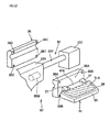
- FIG. 15 is an exploded perspective view of FIG. 14 .
- the step support body 36 is formed as a left-right split type.
- the step support body 36 is supported pivotally through the pivot shaft 23Y.
- symbol 36B denotes a through-hole through which a fastening member (e.g. fastening bolt) for fastening the step support body 36 of the left-right split type passes through.
- Symbol 36C denotes a female screw to which the fastening member made to pass through the through-hole 36B is fastened.
- symbol 23Z is a frame-fixed part that is joined to the rear end of the pivot shaft 23Y and is fixed to a vehicle body frame 2.
- the pivot shaft 23Y extends along the vehicle body front-rear direction. Therefore, the pillion step 81 supported by the step support body 36 can be supported pivotally from the neutral position toward the side on which the footrest surface 81A becomes an inclined surface in which the position of the vehicle body outside is raised toward the vehicle body upper side relative to the position of the vehicle body inside.
- the step support body 36 serves as both the above-described base part 83 supported by the frame part 23X forming part of the vehicle body frame 2 and the above-described pivot part 84 that pivotally supports the pillion step 81 with the intermediary of the pivot shaft 23Y.
- An actuator 90 that causes the pillion step 81 to pivot has a motor 90M disposed in the step support body 36 and rotationally drives the step support body 36 through a converting mechanism (not shown, e.g. eccentric cam) that converts the rotation of this motor 90M to a rotational force of the step support body 36. Due to this, through driving control of the motor 90M by the ECU 100, the same control of the pillion steps 81 as the first embodiment can be applied. This can achieve various kinds of effects such as the effect that the passenger can be induced to perform knee grip according to the traveling status of the motorcycle 1 as with the first embodiment.
- the frame part 23X forming part of the vehicle body frame 2 is provided with the pivot shaft 23Y and the pillion step 81 is pivotally supported with the intermediary of this pivot shaft 23Y.
- the exposure of the external of a step operating mechanism 82 that causes the pillion step 81 to pivot can be suppressed and appearance similar to that of existing motorcycles can be obtained.
- step support body 36 is rotatably supported on the pivot shaft 23Y
- a configuration may be employed in which the step support body 36 is integrally joined to the rotating shaft of the motor 90M and is integrally rotated according to the rotation of the rotating shaft.
- FIG. 16 is a diagram showing the right main step 28 with the peripheral configuration.
- FIG. 17 is a diagram showing the left main step 28 with the peripheral configuration.
- the left and right main steps 28 are supported by left and right main step holders 27 functioning as base parts supported by the rear lower parts of left and right pivot frames 23.
- a heel guard 27A is monolithically formed. This allows the rider to easily press the motorcycle 1 with the intermediary of the heel guards 27A and guards components disposed inside the heel guards 27A (e.g. master cylinder 29A actuated in association with a brake pedal 29, in FIG. 16 ) from the feet of the rider.
- Each main step holder 27 monolithically includes an overlapping part 27K that overlaps with the pivot frame 23 in the vehicle width direction and this overlapping part 27K is pivotally joined to the pivot frame 23 with the intermediary of a pivot shaft 84A.
- the overlapping part 27K extends forward toward the inside of the pivot frame 23 in the vehicle width direction and thereby overlaps with the pivot frame 23 in the vehicle width direction on the front side of the main step 28, and the pivot frame 23 is pivotally supported on the basis of the pivot shaft 84A extending along the vehicle width direction.
- an elongated hole 84N extending along the pivot direction on the basis of the pivot shaft 84A is formed in either one of the overlapping part 27K of the main step holder 27 and the region of the pivot frame 23 overlapping with this overlapping part 27K (in the present configuration, on the side of the main step holder 27).
- a support part 84S that extends along the vehicle width direction and is disposed in the elongated hole 84N is provided.
- These elongated hole 84N and support part 84S function as a restricting part 84K that restricts the pivot range of the pivot frame 23 and allow the height of the main step 28 to be changed between a low position shown by a solid line in FIGS. 16 and 17 and a high position shown by a two-dot chain line in FIGS. 16 and 17 .
- the low position is similar to the conventional fixed position at the time of riding.
- arm parts 87 (moved parts) extending to the vehicle body inside of the pivot frames 23 in the range between the low position and the high position are monolithically provided.
- an actuator 90 that actuates a respective of the arm parts 87 independently is disposed.
- a movable part 90A of each actuator 90 abuts against the upper surface of the respective one of the arm parts 87 and presses the respective one of the arm parts 87 downward. Thereby, the movable parts 90A can each change the height of a respective one of the main steps 28 independently and keep the height.
- the height of footrest surfaces 28A of the main steps 28 can be vertically changed by the step operating mechanisms 82 including the left and right actuators 90, with the footrest surfaces 28A kept as substantially horizontal surfaces (flat) along the vehicle width direction.
- the ECU 100 that controls each actuator 90 controls the actuator 90 to increase the height of the step position on the opposite side to the turn direction of the vehicle. Specifically, the ECU 100 determines whether or not the vehicle speed is zero on the basis of a detection result of the vehicle speed sensor 102. If the vehicle speed is not zero, the ECU 100 determines whether or not turn operation is carried out (including whether or not the present status is immediately before turn operation) on the basis of the tilt of the vehicle body (roll angle), the roll rate (the amount of change in the roll angle per predetermined time), the steering angle of the front wheel 5, and specific information from the navigation device 109 (information or notification indicating that the traveling forward side is in a situation involving a turn, specifically e.g. notification of a sharp curve).
- the navigation device 109 information or notification indicating that the traveling forward side is in a situation involving a turn, specifically e.g. notification of a sharp curve.
- the ECU 100 sets the step position on the opposite side to the turn direction at the above-described high position and keeps the other step position at the above-described low position. In the other cases, i.e. if turn operation is not carried out or if the vehicle speed is zero, the ECU 100 keeps the left and right main steps 28 at the low position, which is the conventional fixed position at the time of riding.
- the motorcycle 1 includes the step operating mechanisms 82 that change the height of the main steps 28 and the ECU 100 carries out control to raise the height of the main step 28 on the opposite side to a turn direction in response to turn operation to the motorcycle 1.
- the main step 28 can be moved to a position to which the load to the outside at the time of the turn can be easily applied. This allows the rider to easily apply the outside foot load to the main step 28 and thus easily hold on. This can induce the rider to take a proper riding posture suitable for the traveling status of the motorcycle 1.
- main step holders 27 supporting the main steps 28 are swingably supported on the pivot frames 23 so that the height of the main steps 28 may be changed. This can reduce dedicated components for changing the height of the main steps 28 and provide a simple structure.
- the main step holders 27 include the arm parts 87 extending to the vehicle body inside of the pivot frames 23 and the actuators 90 that actuate the arm parts 87 are disposed on the vehicle body inside of the pivot frames 23. This can achieve various kinds of effects similar to those of the above embodiments, such as the effect that the actuators 90 can be disposed at positions that are difficult to see from the vehicle body outside.
- a seventh embodiment is another embodiment of the case in which the present invention is applied to the main steps 28 (rider steps).
- Left and right step operating mechanisms 82 that change the step position of left and right main steps 28 are identical to each other. Therefore, only the right side will be described below.
- Members corresponding to the respective members in the above respective embodiments are shown with the same symbols and different points will be described.
- FIG. 18 is a diagram obtained when the right main step 28 is viewed with the peripheral configuration from the vehicle body right side.
- FIG. 19 is a perspective view obtained when FIG. 18 is viewed from the vehicle body right front side.
- a main step holder 27 is fastened and fixed to a pivot frame 23 with the intermediary of a fastening part 27T and functions as a base part supported by the pivot frame 23.
- This main step holder 27 is provided with a pivot part 84 that supports the main step 28 pivotally (escapably) toward the rear upper side.
- the pivot part 84 pivotally supports a base end part 28K of the main step 28 with the intermediary of a pivot shaft 84S that is along the vehicle body front-rear direction and is inclined to have the lowered rear part.
- the pivot part 84 supports the main step 28 pivotally to a neutral position (position shown by a solid line in FIG. 18 ) at which a footrest surface 28A of the main step 28 is set to a horizontal surface extending outward in the vehicle width direction when the vehicle body stands uptight and an inclined position (position shown by a two-dot chain line in FIG. 18 ) at which the footrest surface 28A is set to an inclined surface in which the position of the vehicle body outside is raised toward the vehicle body upper side relative to the position of the vehicle body inside when the vehicle body stands uptight.
- an arm part 87 (moved part) extending toward the vehicle body inside of the main step holder 27 at the neutral position and the inclined position is monolithically provided.
- an actuator 90 that actuates the arm part 87 independently is disposed.
- a movable part 90A of the actuator 90 can set the main step 28 at the above-described neutral position and inclined position through the pivot part 84 by abutting against the upper surface of the arm part 87 and pressing the arm part 87 downward.
- the rider By supporting the main steps 28 in such a manner that the main steps 28 can pivot by the actuators 90 toward the side on which at least the footrest surface 28A becomes an inclined surface in which the position of the vehicle body outside is raised toward the vehicle body upper side relative to the position of the vehicle body inside, the rider can be induced to perform knee grip (in the case of the rider, the state in which the rider lightly clamps the fuel tank 9 by both knees).
- step inclining control to change the position of the main steps 28 so that the footrest surfaces 28A of the main steps 28 may each become an inclined surface in which the position of the vehicle body outside is raised toward the vehicle body upper side relative to the position of the vehicle body inside can be carried out in response to acceleration operation, deceleration operation, and turn operation to the motorcycle 1. Therefore, various kinds of effects such as the effect that the rider can be induced to perform knee grip suitable for the traveling status of the motorcycle 1 can be achieved.
- the footrest surfaces 28A of the main steps 28 are each set to the inclined surface in which the position of the vehicle body outside is raised toward the vehicle body upper side relative to the position of the vehicle body inside by using the pivot parts 84 that support the main steps 28 escapably toward the rear upper side.
- the main steps 28 have the arm parts 87 extending to the vehicle body inside of the main step holders 27 and the actuators 90 that actuate the arm parts 87 are disposed on the vehicle body inside of the main step holders 27.
- This can achieve various kinds of effects similar to those of the above embodiments, such as the effect that the actuators 90 can be disposed at positions that are difficult to see from the vehicle body outside.
- the footrest surfaces 28A of the main steps 28 may be set to inclined surfaces only at the time of acceleration operation and deceleration operation to the motorcycle 1 and the footrest surfaces 28A may be kept at the neutral position, at which they are flat, at the time of turn operation.
- the footrest surfaces 28A of the main steps 28 (rider steps) may be set to inclined surfaces only at the time of deceleration operation to the motorcycle 1. The point is that it suffices that the footrest surfaces 28A of the main steps 28 (rider steps) are set to inclined surfaces in response to at least any of acceleration operation, deceleration operation, and turn operation to the motorcycle 1 and knee grip is induced according to the traveling status of the motorcycle 1.
- the ECU 100 may carry out control to change the inclination angle of the footrest surface 81A of the pillion step 81 or the footrest surface 28A of the main step 28 according to any of the acceleration (including the deceleration) and the amount of turn of the motorcycle 1.
- the acceleration including the deceleration
- the step inclining control is carried out in response to acceleration operation, deceleration operation, and turn operation to the motorcycle 1 .
- the step inclining control may be carried out in response to at least any of acceleration operation, deceleration operation, and turn operation.
- the present invention is not limited thereto and can be widely applied to vehicles such as saddle-type vehicles including the steps 28 and 81 on which occupants (including driver and passenger) put feet.
- the saddle-type vehicles include overall vehicles an occupant rides astride the vehicle body and are vehicles including not only motorcycles (including motorized bicycles) but also three-wheeled vehicles and four-wheeled vehicles such as ATV (rough terrain vehicles).
- the power unit of the vehicle may be other than the engine 6 and may be e.g. a motor, of course.
Landscapes
- Engineering & Computer Science (AREA)
- Mechanical Engineering (AREA)
- Physics & Mathematics (AREA)
- General Physics & Mathematics (AREA)
- Automation & Control Theory (AREA)
- Mechanical Control Devices (AREA)
Abstract
Description
- The present invention relates to a vehicle including steps on which an occupant puts feet.
- Steps of a motorcycle are members for keeping the riding posture of a driver and a passenger and play an important role in actions such as knee grip and load shift at the time of acceleration, deceleration, and turn (refer to
JP 201367182 A - Conventionally, the positions of steps are fixed in the riding state in order to keep the riding posture. However, if step positions suitable for the traveling status can be offered, it becomes possible to facilitate a more proper riding posture, which enables more enjoyable driving and tandem traveling.
- The present invention is made in view of the above-described circumstances and an object thereof is to provide a vehicle that can induce an occupant to take a riding posture suitable for the traveling status of the vehicle.
- To solve the above-described problem, the present invention provides a vehicle that includes steps on which an occupant puts feet and is characterized by including a step operating mechanism that changes a step position and a control unit that changes a position of the step in response to at least any of acceleration operation, deceleration operation, and turn operation to the vehicle.
- In the above configuration, the step operating mechanism may be a mechanism that changes height of the step for a driver, and the control unit may carry out control to raise height of the step position on an opposite side to turn direction of the vehicle.
- Furthermore, in the above configuration, the step operating mechanism may be a mechanism that causes the step for a driver to pivot, and the control unit may carry out step inclining control to cause the step for a driver to pivot in order for a footrest surface of the step to become an inclined surface in which a position of vehicle body outside is raised toward a vehicle body upper side relative to a position of vehicle body inside in response to at least any of acceleration operation, deceleration operation, and turn operation to the vehicle.
- Moreover, in the above configuration, the step operating mechanism may be a mechanism that causes the passenger step on which a passenger puts a foot to pivot, and the control unit may carry out step inclining control to cause the passenger step to pivot in order for a footrest surface of the passenger step to become an inclined surface in which a position of vehicle body outside is raised toward a vehicle body upper side relative to a position of vehicle body inside in response to at least any of acceleration operation, deceleration operation, and turn operation to the vehicle.
- In the above configuration, in a case in which vehicle speed is zero, the control unit may determine that the vehicle is in a starting preparatory state when a clutch of the vehicle is blocking power transmission and a shift stage of the vehicle is other than neutral and carry out the step inclining control when determining that the vehicle is in the starting preparatory state, and the control unit may carry out control to move the passenger step to a neutral position at which the footrest surface is flat when determining that the vehicle is not in the starting preparatory state.
- Furthermore, in the above configuration, in a case in which vehicle speed is other than zero, the control unit may carry out the step inclining control when acceleration of the vehicle is positive acceleration equal to or higher than a predetermined value and when the acceleration of the vehicle is negative acceleration equal to or lower than a predetermined value, and carry out control to move the passenger step to a neutral position at which the footrest surface is flat when the acceleration of the vehicle falls within a predetermined range.
- In addition, in the above configuration, inclination angle of the footrest surface may be changed according to any of the acceleration of the vehicle and an amount of turn in the step inclining control.
- Moreover, in the above configuration, the step operating mechanism may include a base part supported by the vehicle, a pivot part that pivotally supports the passenger step to the base part, and an actuator that causes the passenger step to pivot. Furthermore, the pivot part may support the passenger step pivotally toward a side on which at least the footrest surface becomes an inclined surface in which the position of the vehicle body outside is raised toward the vehicle body upper side relative to the position of the vehicle body inside, and the passenger step may be monolithically provided with a moved part moved by the actuator.
- Furthermore, in the above configuration, the pivot part may allow the passenger step to pivot to a housing position, and the moved part may get away from a movable part of the actuator when the passenger step pivots toward the housing position.
- In addition, in the above configuration, the movable part of the actuator may be disposed on the vehicle body inside relative to the base part. Furthermore, the moved part may extend to the vehicle body inside relative to the pivot part and the passenger step may extend from the pivot part to the vehicle body outside.
- Moreover, in the above configuration, the step operating mechanism may include a base part supported by the vehicle, a first pivot part that supports, to the base part, the passenger step pivotally toward a side on which at least the footrest surface becomes an inclined surface in which the position of the vehicle body outside is raised toward the vehicle body upper side relative to the position of the vehicle body inside, a second pivot part that supports, to the base part, the passenger step pivotally in a direction different from direction of pivot by the first pivot part, and an actuator that causes the passenger step to pivot through the first pivot part. Furthermore, the passenger step may be monolithically provided with a moved part moved by the actuator.
- Furthermore, in the above configuration, the step operating mechanism may include a base part that is supported by the vehicle and pivotally supports the passenger step, a pivot part that supports the passenger step pivotally toward a side on which at least the footrest surface becomes an inclined surface in which the position of the vehicle body outside is raised toward the vehicle body upper side relative to the position of the vehicle body inside, a moved part that is pivotally supported by the base part below the base part and causes the passenger step to pivot through the pivot part, and an actuator that causes the passenger step to pivot through the moved part. In addition, the actuator may have a drum that winds up cables each connected to a respective one of the passenger steps on left and right sides and each of the cables may be made to pass through a lower side of the base part to be joined to the moved part.
- Moreover, in the above configuration, the step operating mechanism may include a base part that is supported by the vehicle and pivotally supports the passenger step, a pivot part that supports the passenger step pivotally toward a side on which at least the footrest surface becomes an inclined surface in which the position of the vehicle body outside is raised toward the vehicle body upper side relative to the position of the vehicle body inside, a moved part that is pivotally supported by the base part below the base part and causes the passenger step to pivot through the pivot part, and an actuator that causes the passenger step to pivot through the moved part. The actuator may have a drum that winds up cables each connected to a respective one of the passenger steps on left and right sides and each of the cables may be made to pass through inside of the base part in vehicle width direction to be joined to the moved part.
- In the present invention, the vehicle includes the step operating mechanism that changes the position of the step on which an occupant puts a foot and the control unit that changes the position of the step in response to at least any of acceleration operation, deceleration operation, and turn operation to the vehicle. Thus, the occupant can be induced to take a riding posture suitable for the traveling status of the vehicle.
- Furthermore, if the step operating mechanism is a mechanism that changes the height of the step for a driver and the control unit carries out control to raise the height of the step position on the opposite side to the turn direction of the vehicle, the main step can be moved to a position to which the load to the outside at the time of the turn can be easily applied, which allows the driver to easily hold on.
- In addition, the driver can be induced to perform knee grip suitable for the traveling status of the vehicle if the step operating mechanism is a mechanism that causes the step for the driver to pivot and the control unit carries out step inclining control to cause the step for the driver to pivot in order for the footrest surface of the step to become an inclined surface in which the position of the vehicle body outside is raised toward the vehicle body upper side relative to the position of the vehicle body inside in response to at least any of acceleration operation, deceleration operation, and turn operation to the vehicle.
- Moreover, a passenger can be induced to perform knee grip suitable for the traveling status of the vehicle if the step operating mechanism is a mechanism that causes the passenger step on which the passenger puts a foot to pivot and the control unit carries out step inclining control to cause the passenger step to pivot in order for the footrest surface of the passenger step to become an inclined surface in which the position of the vehicle body outside is raised toward the vehicle body upper side relative to the position of the vehicle body inside in response to at least any of acceleration operation, deceleration operation, and turn operation to the vehicle.
- Furthermore, the passenger can be induced to take a proper riding posture according to operation in association with starting preparation if the following configuration is employed. Specifically, in the case in which the vehicle speed is zero, the control unit determines that the vehicle is in the starting preparatory state when the clutch of the vehicle is blocking power transmission and the shift stage of the vehicle is other than neutral and carries out the step inclining control when determining that the vehicle is in the starting preparatory state, and the control unit carries out control to move the passenger step to the neutral position at which the footrest surface is flat when determining that the vehicle is not in the starting preparatory state.
- In addition, knee grip can be properly induced according to the vehicle body behavior at the time of traveling if the following configuration is employed. Specifically, in the case in which the vehicle speed is other than zero, the control unit carries out the step inclining control when the acceleration of the vehicle is positive acceleration equal to or higher than a predetermined value and when the acceleration of the vehicle is negative acceleration equal to or lower than a predetermined value, and carries out control to move the passenger step to the neutral position at which the footrest surface is flat when the acceleration of the vehicle falls within a predetermined range.
- If the inclination angle of the footrest surface is changed according to any of the acceleration of the vehicle and the amount of turn in the step inclining control, it is possible to convey change in the behavior and the degree of change to the passenger according to the acceleration or the amount of turn.
- Furthermore, if the following configuration is employed, it is possible to control the inclination of the passenger step by utilizing the pivot when the passenger step is housed while providing the passenger step that can be housed by being brought close to the vehicle body side through the pivot part. Specifically, the step operating mechanism includes the base part supported by the vehicle, the pivot part that pivotally supports the passenger step to the base part, and the actuator that causes the passenger step to pivot. Furthermore, the pivot part supports the passenger step pivotally toward the side on which at least the footrest surface becomes an inclined surface in which the position of the vehicle body outside is raised toward the vehicle body upper side relative to the position of the vehicle body inside, and the passenger step is monolithic ally provided with the moved part moved by the actuator.
- In addition, if the pivot part allows the passenger step to pivot to the housing position and the moved part gets away from the movable part of the actuator when the passenger step pivots toward the housing position, the movable part of the actuator does not hinder the movement of the passenger step to the housing position and the passenger step can be easily operated to the housing position manually.
- Moreover, the movable part of the actuator can be disposed at a position hidden from the vehicle body outside if the following configuration is employed. Specifically, the movable part of the actuator is disposed on the vehicle body inside relative to the base part. Furthermore, the moved part extends to the vehicle body inside relative to the pivot part and the passenger step extends from the pivot part to the vehicle body outside.
- Furthermore, if the following configuration is employed, the passenger step can be caused to pivot also in a direction other than the direction of the step inclining control, which improves the flexibility in the pivot direction. Specifically, the step operating mechanism includes the base part supported by the vehicle, the first pivot part that supports, to the base part, the passenger step pivotally toward the side on which at least the footrest surface becomes an inclined surface in which the position of the vehicle body outside is raised toward the vehicle body upper side relative to the position of the vehicle body inside, the second pivot part that supports, to the base part, the passenger step pivotally in a direction different from the direction of pivot by the first pivot part, and the actuator that causes the passenger step to pivot through the first pivot part. Furthermore, the passenger step is monolithically provided with the moved part moved by the actuator.
- Moreover, if the following configuration is employed, the left and right passenger steps can be driven by one actuator and the cables and the joining parts between the cables and the moved parts can be disposed at positions that are difficult to see from the vehicle body outside. Specifically, the step operating mechanism includes the base part that is supported by the vehicle and pivotally supports the passenger step, the pivot part that supports the passenger step pivotally toward the side on which at least the footrest surface becomes an inclined surface in which the position of the vehicle body outside is raised toward the vehicle body upper side relative to the position of the vehicle body inside, the moved part that is pivotally supported by the base part below the base part and causes the passenger step to pivot through the pivot part, and the actuator that causes the passenger step to pivot through the moved part. In addition, the actuator has the drum that winds up the cables each connected to a respective one of the passenger steps on the left and right sides and each of the cables is made to pass through the lower side of the base part to be joined to the moved part.
- In addition, if the following configuration is employed, the left and right passenger steps can be driven by one actuator and the cables and the joining parts between the cables and the moved parts can be disposed at positions that are difficult to see from the vehicle body outside. Specifically, the step operating mechanism includes the base part that is supported by the vehicle and pivotally supports the passenger step, the pivot part that supports the passenger step pivotally toward the side on which at least the footrest surface becomes an inclined surface in which the position of the vehicle body outside is raised toward the vehicle body upper side relative to the position of the vehicle body inside, the moved part that is pivotally supported by the base part below the base part and causes the passenger step to pivot through the pivot part, and the actuator that causes the passenger step to pivot through the moved part. In addition, the actuator has the drum that winds up the cables each connected to a respective one of the passenger steps on the left and right sides and each of the cables is made to pass through the inside of the base part in the vehicle width direction to be joined to the moved part.
-
FIG. 1 is a right side view of a motorcycle according to a first embodiment of the present invention. -
FIG. 2 is a perspective view showing a left pillion step with a step operating mechanism. -
FIG. 3 is a diagram obtained whenFIG. 2 is viewed from the vehicle body left side. -
FIG. 4 shows diagrams depicting posture change of the pillion step by an actuator:FIG. 4(A) is a diagram showing a state with a neutral position;FIG. 4(B) is a diagram showing a state with a first inclination angle; andFIG. 4(C) is a diagram showing a state with a second inclination angle. -
FIG. 5 is a diagram showing the internal structure of the actuator. -
FIG. 6 is a diagram showing the internal structure of the actuator according to a modification example. -
FIG. 7 is a block diagram showing an ECU that controls the actuators with the peripheral configuration. -
FIG. 8 is a flowchart showing control of the pillion steps. -
FIG. 9 is a perspective view showing a pillion step of a second embodiment with a step operating mechanism. -
FIG. 10 is a diagram obtained whenFIG. 9 is viewed from the vehicle body left side. -
FIG. 11 is a diagram showing pillion steps of a third embodiment with step operating mechanisms. -
FIG. 12 shows diagrams depicting a pillion step of a fourth embodiment with a step operating mechanism:FIG. 12(A) is a diagram as viewed from the vehicle body left side andFIG. 12(B) is a diagram as viewed from the vehicle body front side. -
FIG. 13 is a left side view of a motorcycle according to a fifth embodiment. -
FIG. 14 is a perspective view showing a left pillion step with the peripheral configuration. -
FIG. 15 is an exploded perspective view ofFIG. 14 . -
FIG. 16 is a diagram showing a right main step of a sixth embodiment with a step operating mechanism. -
FIG. 17 is a diagram showing a left main step of the sixth embodiment with the step operating mechanism. -
FIG. 18 is a diagram obtained when a right main step of a seventh embodiment is viewed with a step operating mechanism from the vehicle body right side. -
FIG. 19 is a perspective view obtained when the right main step of the seventh embodiment is viewed with the step operating mechanism from the vehicle body right front side. - Motorcycles according to embodiments of the present invention will be described below with reference to the drawings. In the description, directions such as front, rear, left, right, upward, and downward directions are the same as those with respect to the vehicle body unless particularly noted. Furthermore, symbol FR shown in the respective diagrams indicates the vehicle body front side. Symbol UP indicates the vehicle body upper side and symbol LF indicates the vehicle body left side.
-
FIG. 1 is a right side view of amotorcycle 1 according to a first embodiment of the present invention. - This
motorcycle 1 includes avehicle body frame 2, a pair of left and rightfront forks 3 steerably supported by ahead pipe 20 of thevehicle body frame 2, asteering handlebar 4 that is attached to the upper end parts of thesefront forks 3 and is disposed at the upper part of the vehicle body front part, afront wheel 5 rotatably supported by thefront forks 3, and an engine 6 (power unit) supported by thevehicle body frame 2 at substantially the center of the vehicle body. Themotorcycle 1 further includes a swingarm 7 (referred to also as rear fork) supported by thevehicle body frame 2 vertically swingably, arear wheel 8 rotatably supported by the rear end part of thisswingarm 7, afuel tank 9 disposed at the upper part of thevehicle body frame 2, anoccupant seat 10 disposed on the rear side of thisfuel tank 9, and avehicle body cowl 11 covering the vehicle body. - The
vehicle body frame 2 includes a pair of left and rightmain frames 21 extending from thehead pipe 20 toward the rear lower side, a pair of left and right pivot frames 23 that are connected to the rear parts of themain frames 21 and extend downward, and arear frame 25 extending from the upper parts of the pivot frames 23 toward the rear upper side. - The front upper part of the
engine 6 is supported by themain frames 21 and the rear part of theengine 6 is supported by the pivot frames 23. Thereby, theengine 6 is supported below themain frames 21 and in front of the pivot frames 23. Theengine 6 is a four-cylinder engine provided with a transmission mechanism and a clutch mechanism (not shown). The shift stage can be changed among shift stages from first to sixth for example by the transmission mechanism according to gearshift operation by a rider (driver), and power transmission to the rear wheel 8 (drive wheel) can be blocked/connected (disconnected/connected) by the clutch mechanism according to clutch operation by the rider. - By the pair of left and right pivot frames 23, the front end part of the
swingarm 7 is pivotally supported and a pair of left and right main steps 28 (rider steps) on which the rider (driver) puts feet are supported with the intermediary ofmain step holders 27. - Furthermore, the
fuel tank 9 is supported on themain frames 21 and stores the fuel to be supplied to theengine 6. Theoccupant seat 10 is supported on therear frame 25. - The
vehicle body cowl 11 is formed as a full cowl type covering substantially the whole of the vehicle body. It includes afront cowl 12 covering the vehicle body front part, a pair of left and right side cowls 13 that are provided consecutively with thisfront cowl 12 and cover the left and right sides of the vehicle body, and an undercowl 14 covering the vehicle body lower part. - A
headlight 15 is provided on the front surface of thefront cowl 12. A windscreen (windshield) 16 is attached to the upper part of thefront cowl 12. Left andright mirrors 17 are attached to the left and right sides of thefront cowl 12. Thismotorcycle 1 includes, as other cover members, afront fender 18 covering the upper side of thefront wheel 5 and arear fender 19 covering the upper side of therear wheel 8. In the diagram,symbol 31 denotes an exhaust muffler that is disposed on the right side of therear wheel 8 and emits an exhaust gas of theengine 6. - This
motorcycle 1 is formed as a two-seater vehicle a rider and a passenger (fellow passenger) can ride. Theoccupant seat 10 is formed as a seat having a front seat 41 (rider riding part) on which the rider sits and a rear seat 42 (passenger riding part) on which the passenger sits as front and rear parts thereof. - By the
rear frame 25, a pair of left and right pillion steps 81 (passenger steps) on which the passenger puts feet are pivotally supported with the intermediary of astep operating mechanism 82. - In tandem traveling, the passenger often moves to a large extent due to acceleration, deceleration, or turn according to operation by the rider. As one of riding techniques of the passenger, there is a state in which the passenger lightly clamps the waist part of the rider by both knees (hereinafter, referred to as knee grip).
- It is difficult for the passenger to always perform knee grip during tandem traveling. Therefore, the passenger is required to perform knee grip according to the status. However, it is difficult for the passenger to accurately anticipate the operation of the rider and therefore the passenger needs to perform knee grip while relying on experience.
- The riding posture of the passenger also affects the driving of the vehicle. Therefore, the rider can enjoy the tandem traveling more if the motion of the passenger can be properly suppressed.
- Therefore, in the present configuration, the
step operating mechanism 82 that can induce the passenger to perform knee grip according to the traveling status of the vehicle is provided and control of thestep operating mechanism 82 is carried out. The left and right pillion steps 81 andstep operating mechanisms 82 are symmetrical between the left and right sides. In the following, one of the pillion steps 81 and one of thestep operating mechanisms 82 will be described. -
FIG. 2 is a perspective view showing theleft pillion step 81 with thestep operating mechanism 82 andFIG. 3 is a diagram obtained whenFIG. 2 is viewed from the vehicle body left side. - The
step operating mechanism 82 monolithically includes abase part 83 supported by therear frame 25 and apivot part 84 that extends from thebase part 83 toward the outside in the vehicle width direction and pivotally supports thepillion step 81 with the intermediary of apivot shaft 84A. - The
base part 83 is composed of a metal material such as an aluminum alloy and is formed into a triangular frame shape in side view. Thebase part 83 pivotally supports thepillion step 81 with the intermediary of thepivot part 84 at the corner part at the lowermost position in the triangle. In other words, thebase part 83 is formed into a frame shape extending downward, rearward, and so forth from the vehicle body frame 2 (rear frame 25, in the present embodiment) toward the position that is the most suitable for the passenger to put a foot on. In thebase part 83, plural through-holes 83A are formed at intervals in a region corresponding to the top side of the triangle and thebase part 83 is fixed to therear frame 25 by fastening members (not shown) through these through-holes 83A. - The
pivot part 84 is formed as a pivotal support part that supports thepillion step 81 pivotally to at least a neutral position at which afootrest surface 81A of thepillion step 81 is set to a horizontal surface extending outward in the vehicle width direction when the vehicle body stands uptight (seeFIG. 2 ) and an inclined position at which thefootrest surface 81A is set to an inclined surface in which the position of the vehicle body outside is raised toward the vehicle body upper side relative to the position of the vehicle body inside when the vehicle body stands uptight. - The
pillion step 81 has astep part 85 that is pivotally supported by thepivot part 84 with the intermediary of thepivot shaft 84A and extends outward in the vehicle width direction at the neutral position and the inclined position, and includes afootrest part 86 forming thefootrest surface 81A on which the passenger puts a foot at the upper part of thisstep part 85 monolithically or as a separate body. At abase end part 81K (equivalent to the inside end part in the vehicle width direction) of thisstep part 85, an arm part 87 (moved part) extending toward the vehicle body inside at the neutral position and the inclined position is monolithically provided. - As shown in
FIG. 2 , by setting thepillion step 81 at the neutral position, at which thefootrest surface 81A is set to a horizontal surface, it becomes possible for the passenger sitting on therear seat 42 to easily put a foot on thefootrest surface 81A. Furthermore, at this neutral position, the passenger can easily step foot on thefootrest surface 81A when riding or getting down themotorcycle 1 and it is also possible to sufficiently ensure easiness of riding and alighting. This neutral position is equivalent to the use position when the passenger rides the vehicle in conventional motorcycles. The neutral position of the present embodiment is equivalent to a horizontal position at which thefootrest surface 81A of thepillion step 81 is set to a horizontal surface. However, the neutral position may be a position at which thefootrest surface 81A is set to a slightly-inclined surface. - As shown in
FIG. 3 , thepivot shaft 84A, which defines the pivot axis line of thepillion step 81, is supported with such a posture as to be along the vehicle body front-rear direction and be slightly inclined to have the lowered rear part. Because thepivot shaft 84A is along the vehicle body front-rear direction, when thepillion step 81 pivots upward from the neutral position shown by a solid line inFIG. 3 on the basis of thepivot shaft 84A, thefootrest surface 81A becomes an inclined surface in which the position of the vehicle body outside is raised toward the vehicle body upper side relative to the position of the vehicle body inside. Furthermore, the inclination angle thereof can be arbitrarily changed by changing the amount of pivot (pivot angle). - When the
pillion step 81 pivots to a vertical position on the basis of thepivot shaft 84A, thefootrest surface 81A of thepillion step 81 substantially abuts against thebase part 83 and the further pivot of thepillion step 81 is restricted. This position is equivalent to a housing position at which the whole of thepillion step 81 is close to thebase part 83 and is folded to the inside in the vehicle width direction. That is, when thepillion step 81 is not used, setting thepillion step 81 at this housing position can suppress the extension of thepillion step 81 toward the outside in the vehicle width direction. Furthermore, thispillion step 81 can be made to pivot and move to the housing position by an occupant manually. InFIG. 3 , thepillion step 81 at the housing position is shown by a two-dot chain line. - Furthermore, as shown in
FIG. 3 , because thepivot shaft 84A is inclined to have the lowered rear part, thepillion step 81 pivots along a straight line that is orthogonal to thispivot shaft 84A and extends toward the rear upper side when being viewed from the vehicle body lateral side. Thus, when being at the housing position, thepillion step 81 can be disposed along the rear edge part of thebase part 83 extending toward the rear upper side and is allowed to have appearance integrated with thebase part 83. - The
step operating mechanism 82 includes anactuator 90 that causes thepillion step 81 to pivot. Thisactuator 90 is a linear actuator having amovable part 90A that can linearly move. As shown inFIGS. 2 and3 , theactuator 90 is attached on the vehicle body inside of thebase part 83 along the rear edge of thebase part 83 and is disposed to allow themovable part 90A to advance downward and retreat. -
FIG. 4 shows diagrams depicting the posture change of thepillion step 81 by theactuator 90.FIG. 4(A) shows a state with the neutral position.FIG. 4(B) shows a state with a first inclination angle θA.FIG. 4(C) shows a state with a second inclination angle θB (θB > θA). - As shown in
FIGS. 4(A) to 4(C) , themovable part 90A of theactuator 90 can set thepillion step 81 at each of the neutral position (seeFIG. 4(A) ), the first inclination angle θA (seeFIG. 4(B) ), and the second inclination angle θB (seeFIG. 4(C) ) by abutting against the upper surface of thearm part 87 of thepillion step 81 and pressing thearm part 87 downward. - The first and second inclination angles θA and θB are angles at which the
footrest surface 81A is an inclined surface in which the position of the vehicle body outside is raised toward the vehicle body upper side relative to the position of the vehicle body inside when being viewed with the posture when the vehicle body stands upright. The first and second inclination angles θA and θB are rotation angles from the neutral position based on the pivot axis and satisfy a relationship of 90° (angle of the housing position) > second inclination angle θB > first inclination angle θA. For example, the second inclination angle θB is 20° and the first inclination angle θA is 10°. - Step inclining control may be employed in which a force to cause the
pillion step 81 to pivot is so generated that the force to incline thepillion step 81 becomes larger depending on the difference between a target value according to the acceleration and the present position. - In
FIGS. 4(A) to 4(C) , symbol Ft denotes a foot of a passenger put on thepillion step 81 and symbol Lf denotes the center axis line of the region from the foot Ft to a knee. - As shown in
FIG. 4(A) , at the neutral position, thefootrest surface 81A is horizontal and therefore the region Lf from the foot Ft put on thefootrest surface 81A to the knee stands substantially vertically. In contrast, at the first inclination angle θA, thefootrest surface 81A becomes the above-described inclined surface. Thus, as shown inFIG. 4(B) , the region Lf from the foot Ft to the knee is so inclined that its part at a higher level is closer to the inside in the vehicle width direction. That is, the passenger can be induced to a knee grip state in which the passenger clamps the waist part of the rider by the knees. - At the second inclination angle θB, the inclination angle is larger than the first inclination angle θA. Therefore, the knee can be guided to the inside in the vehicle width direction to a larger extent and it becomes possible to induce the knee grip more or induce somewhat stronger knee grip. The first inclination angle θA and the second inclination angle θB may be set to angles suitable for the knee grip as appropriate.
-
FIG. 5 is a diagram showing the internal structure of theactuator 90. - The
actuator 90 is a linear motion mechanism that linearly moves themovable part 90A by using amotor 91 and aball screw 92. Specifically, theactuator 90 has a structure in which themotor 91 whose rotation is controlled by anECU 100 to be described later and theball screw 92 joined to the rotating shaft of themotor 91 are housed in acylindrical actuator case 93 whose lower end is opened and themovable part 90A is screwed to thisball screw 92. Themovable part 90A can move in the axial direction of theball screw 92 by being guided by the inner surface of theactuator case 93 and is so provided as to be incapable of moving in the rotation direction of theball screw 92. - This allows the
movable part 90A to advance and retreat in the axial direction of theball screw 92 according to the rotation of themotor 91. By controlling the amount of rotation of thismotor 91 and the rotation direction, thepillion step 81 can be moved to each of the neutral position, the position of the first inclination angle θA, and the position of the second inclination angle θB shown inFIGS. 4(A) to 4(C) . -
FIG. 6 shows a modification example of theactuator 90. - The
actuator 90 shown inFIG. 6 is a so-called hydraulic cylinder and includes anactuator case 93 configuring a cylinder part forming a hydraulic chamber, themovable part 90A functioning as a piston slidable relative to theactuator case 93, and a biasingmember 94 that biases themovable part 90A toward the retraction side. Furthermore, theactuator 90 includes apump 95 that supplies a hydraulic pressure to the hydraulic chamber of theactuator case 93. Under this configuration, thepump 95 is driven by theECU 100 to be described later. Thereby, a hydraulic pressure is supplied into theactuator case 93 via ahose 96 and themovable part 90A moves according to this hydraulic pressure against the biasing force of the biasingmember 94. This can cause thepillion step 81 to pivot. - The
actuator 90 may be one having a mechanism other than the ball screw mechanism and the hydraulic cylinder and a publicly-known actuator can be widely applied. -
FIG. 7 is a block diagram showing the ECU (electronic control unit) 100, which controls theactuators 90, with the peripheral configuration. - The
ECU 100 is an electrical component unit composed of a computer and various kinds of electronic components and functions as a control unit that controls the respective parts of the vehicle body including theactuators 90. - As shown in
FIG. 7 , besides theactuators 90, sensors, switches, and so forth that detect information on the respective parts of the vehicle body are connected to theECU 100. Specifically, the following components are connected: athrottle opening sensor 101 that detect the degree of opening of a throttle operated by a rider (throttle opening); avehicle speed sensor 102 that detects the vehicle speed; anNe sensor 103 that detects the engine rotation speed; anacceleration sensor 104 that detects the acceleration; agear position sensor 105 that detects the present shift stage; aclutch detecting switch 106 that detects ON (power transmission is blocked)/OFF (power is transmitted) of the clutch mechanism; a gyro sensor 107 (tilt angle sensor) for detecting the tilt of the vehicle body (roll angle) and so forth; asteering angle sensor 108 that detects the steering angle of the front wheel 5 (or handlebar 4); anavigation device 109; aseat switch 110 that detects whether or not a passenger sits on therear seat 42; astep switch 111 that detects whether or not the pillion steps 81 are at a predetermined position (neutral position, in the present embodiment); abrake switch 112 that detects whether or not the rider is carrying out brake operation; and a brake fluidpressure detecting sensor 113 that detects the brake fluid pressure. - The
navigation device 109 is a device that includes a GPS (global positioning system) unit and has a map display function of displaying map information of a surrounding area including the present location on the basis of the present location acquired by the GPS unit, a route guide function of performing a route guide from the present location to a destination set in advance, and so forth. - The map information used by the
navigation device 109 generally includes road information including nodes and links indicating a road network. In recent years, navigation devices having the following functions have come to appearance: a function of detecting, in advance, traveling information on whether or not the road on the traveling forward side curves and so forth by using this road information; and a function of detecting, in advance, whether or not the traveling forward side is in a situation involving change in the vehicle body behavior (e.g. the existence of sharp curve, temporary stop site, and railroad crossing) on the basis of additional information added in advance. - The
navigation device 109 of the present embodiment has a function of detecting whether or not the traveling forward side is in a situation involving change in the vehicle body behavior in advance and notifying theECU 100 of the detected information. - The brake fluid
pressure detecting sensor 113 detects whether or not the brake is being actuated on the basis of the brake fluid pressure, i.e. whether or not the brake is being operated. Therefore, by using the results of both thebrake switch 112 and the brake fluidpressure detecting sensor 113, the accuracy of the detection of whether or not the brake is being operated is enhanced compared with the case of using only the result of either one.FIG. 7 shows part of the configurations connected to theECU 100. TheECU 100 carries out engine control (intake control and ignition control) and so forth. - Possibly the
seat switch 110 will react to baggage. In view of such a situation, an ON/OFF function based on a manual switch may be provided so that the step inclining control may be prevented. -
FIG. 8 is a flowchart showing the control of the pillion steps 81. This flowchart shows processing executed when theECU 100 has determined that a passenger is currently riding themotorcycle 1 on the basis of a detection result of theseat switch 110. However, if theseat switch 110 is not provided, this processing may be repeatedly executed at a predetermined interrupt cycle. - In a step S1A, the
ECU 100 determines whether or not the vehicle speed is zero on the basis of a detection result of thevehicle speed sensor 102. If the vehicle speed is zero, theECU 100 executes processing of determination of whether or not themotorcycle 1 is in a starting preparatory state (step S2A). In this step S2A, theECU 100 determines whether or not a predetermined condition with which themotorcycle 1 can be determined to be in the starting preparatory state is satisfied. Specifically, on the basis of detection results of theclutch detecting switch 106, thegear position sensor 105, thebrake switch 112, and so forth, theECU 100 determines that themotorcycle 1 is in the starting preparatory state if the clutch is ON (power transmission is blocked) and the shift stage is other than neutral and the brake is being operated. - If determining that the
motorcycle 1 is not in the starting preparatory state, theECU 100 determines whether or not the pillion steps 81 are at the neutral position on the basis of a detection result of the step switch 111 (step S3A). If the pillion steps 81 are not at the neutral position, theECU 100 carries out return control in which theactuators 90 are driven to return the pillion steps 81 to the neutral position (step S4A). In this return control, control to return the pillion steps 81 to the neutral position while smoothly changing the angular velocity of the pillion steps 81 so that the passenger may be prevented from being given a sense of discomfort is carried out. For example, velocity control by which the angular velocity changes in a sinusoidal manner is carried out. On the other hand, if the pillion steps 81 are at the neutral position, theECU 100 temporarily ends this processing and thereafter executes the processing of the step S1A. - If determining in the step S2A that the
motorcycle 1 is in the starting preparatory state, theECU 100 carries out first step raising control (step S5A). This first step raising control is step inclining control in which theactuators 90 are driven to incline the pillion steps 81 to the first inclination angle θA. Specifically, the pillion steps 81 are made to pivot to the first inclination angle θA in a stepwise manner. Inclining the pillion steps 81 to the first inclination angle θA can induce the passenger who puts feet on the pillion steps 81 to perform knee grip and induce the passenger to take a riding posture suitable for behavior change. In addition, by causing the pillion steps 81 to pivot in a stepwise manner, the movement of the pillion steps 81 can be clearly conveyed to the passenger and the passenger can be urged to pay attention to starting. - If the vehicle speed is not zero, the
ECU 100 determines whether or not themotorcycle 1 is in a state of change in the vehicle body behavior (step S6A). The "state of change in the vehicle body behavior" in the step S6A includes both a "state in which change in the vehicle body behavior is anticipated" and "vehicle body behavior is currently changing." If determining that themotorcycle 1 is in the "state of change in the vehicle body behavior," theECU 100 makes transition to a step S7A and determines whether or not themotorcycle 1 is in the "state in which change in the vehicle body behavior is anticipated." - Specifically, the change in the vehicle body behavior can be determined by using any of the throttle opening, change in the vehicle speed or the engine rotation speed, the acceleration, the tilt of the vehicle body (roll angle), the roll rate (the amount of change in the roll angle per predetermined time), the steering angle of the
front wheel 5, the status of brake control, and specific information from the navigation device 109 (information or notification indicating that the traveling forward side is in a situation involving change in the vehicle body behavior, specifically e.g. information or notification indicating the existence of sharp curve, temporary stop site, and railroad crossing). - In the present embodiment, in order to determine whether or not the
motorcycle 1 is in the "state in which change in the vehicle body behavior is anticipated," theECU 100 detects whether or not acceleration operation by the rider is carried out through thethrottle opening sensor 101 and detects whether or not brake operation by the rider is carried out through thebrake switch 112. Furthermore, theECU 100 detects whether or not shift-down operation by the rider is carried out through thegear position sensor 105 and detects whether or not specific information from the navigation device 109 (e.g. information or notification indicating the existence of sharp curve, temporary stop site, and railroad crossing) is received. - That is, the
ECU 100 detects whether or not any of acceleration operation, deceleration operation, and turn operation is carried out or whether or not specific information is received from thenavigation device 109. When detecting any kind of operation or information, theECU 100 determines that themotorcycle 1 is in the "state in which change in the vehicle body behavior is anticipated." - Furthermore, in order to determine whether or not "the vehicle body behavior is currently changing," the
ECU 100 executes the following processing. - The
ECU 100 determines whether themotorcycle 1 is accelerating (speed is increasing) or decelerating (speed is decreasing) on the basis of the acceleration detected by theacceleration sensor 104. At the time of acceleration, theECU 100 carries out acceleration correction in which the acceleration generated after a minute time is estimated from the accelerator opening and the engine rotation speed. At the time of deceleration, theECU 100 carries out deceleration correction in which the negative acceleration (deceleration) generated after a minute time is estimated on the basis of at least any of thebrake switch 112, the brake fluid pressure, the accelerator opening, and the engine rotation speed. TheECU 100 employs the acceleration or deceleration after the correction as a determination value of the vehicle body behavior. Then, theECU 100 determines that "the vehicle body behavior is currently changing" if the determination value surpasses a predefined threshold that is a determination reference value of change in the vehicle body behavior, i.e. if the acceleration or deceleration after the minute time is equal to or higher than a predetermined value. - Furthermore, the
ECU 100 detects the roll angle of the vehicle body and the roll rate through thegyro sensor 107 and detects change in the steering angle through thesteering angle sensor 108. Then, on the basis of them, theECU 100 obtains a determination value of behavior change in the turn direction. TheECU 100 determines that "the vehicle body behavior is currently changing" if this determination value surpasses a predefined threshold that is a determination reference value of change in the vehicle body behavior, i.e. also in the case of a turn equal to or larger than a predetermined turn. In this manner, whether or not "the vehicle body behavior is currently changing" can be accurately determined. - In the case of estimating the acceleration generated after the minute time from the accelerator opening and the engine rotation speed, it is preferable to employ the following way because the acceleration changes depending on the magnitude of the traveling resistance. Specifically, characteristic data of the traveling resistance is held in advance and the traveling resistance is identified in advance on the basis of the immediately-previous accelerator opening, the engine rotation speed, vehicle speed change, and so forth. Then, the acceleration is obtained from the excess driving force in consideration of the characteristic data of this identified traveling resistance. For example, as the characteristic data of the traveling resistance, data made by describing characteristics of the traveling resistance, the engine rotation speed, the accelerator opening, and the acceleration when the driving force is indicated on the ordinate and the speed is indicated on the abscissa is stored, and the acceleration can be obtained on the basis of this data.
- Referring back to
FIG. 8 , if determining that themotorcycle 1 is in the "state in which change in the vehicle body behavior is anticipated," theECU 100 carries out the first step raising control (step S8A). If determining that "the vehicle body behavior is currently changing," theECU 100 carries out second step raising control (step S9A). This second step raising control is control of keeping on driving theactuators 90 toward the larger side of the inclination angle of the pillion steps 81 to keep on applying a force to the passenger. The maximum value of the inclination angle of the pillion steps 81 in this case is set to the second inclination angle θB and excessive inclination of the pillion steps 81 is suppressed. This can induce knee grip to a larger extent and induce the passenger to take a riding posture suitable for the behavior change. - If determining that the
motorcycle 1 is not in the state of behavior change, theECU 100 determines whether or not the pillion steps 81 are at the neutral position on the basis of a detection result of the step switch 111 (step S 10A). If the pillion steps 81 are not at the neutral position, theECU 100 carries out the return control in which theactuators 90 are driven to return the pillion steps 81 to the neutral position (step S11A). Also in this return control, control to return the pillion steps 81 to the neutral position while smoothly changing the angular velocity of the pillion steps 81 so that the passenger may be prevented from being given a sense of discomfort, specifically e.g. velocity control by which the angular velocity changes in a sinusoidal manner, is carried out. - On the other hand, if the pillion steps 81 are at the neutral position, the
ECU 100 temporarily ends this processing and thereafter executes the processing of the step S1A. The above is the control of the pillion steps 81. - As described above, in the present embodiment, the
motorcycle 1 includes thestep operating mechanisms 82 that change the positions of the pillion steps 81. Furthermore, in response to at least any of acceleration operation, deceleration operation, and turn operation to themotorcycle 1, theECU 100 carries out the step inclining control to change the positions of the pillion steps 81 (passenger steps) in such a manner that the footrest surfaces 81A of the pillion steps 81 each become an inclined surface in which the position of the vehicle body outside is raised toward the vehicle body upper side relative to the position of the vehicle body inside. Therefore, the passenger can be induced to perform knee grip according to the behavior of themotorcycle 1 and be informed of behavior change of themotorcycle 1. This can induce the passenger to take a proper riding posture suitable for the traveling status of themotorcycle 1, which facilitates the driving by the rider. Consequently, more enjoyable driving and tandem traveling are enabled. - Furthermore, in the case in which the vehicle speed is zero, the
ECU 100 determines that themotorcycle 1 is in the starting preparatory state when the clutch mechanism possessed by themotorcycle 1 is in the state of blocking power transmission and the shift stage of themotorcycle 1 is other than neutral. When determining that themotorcycle 1 is in the starting preparatory state, theECU 100 carries out the step inclining control. When determining that themotorcycle 1 is not in the starting preparatory state, theECU 100 carries out the return control to move the pillion steps 81 to the neutral position, at which thefootrest surface 81A is flat. This can induce the passenger to take a proper riding posture suitable for starting preparation. - In addition, in the case in which the vehicle speed is other than zero, the
ECU 100 carries out the step inclining control when the acceleration of themotorcycle 1 is positive acceleration equal to or higher than a predetermined value and when the acceleration is negative acceleration equal to or lower than a predetermined value. When the acceleration of themotorcycle 1 falls within a predetermined range, theECU 100 carries out the return control to move the pillion steps 81 to the neutral position, at which thefootrest surface 81A is flat. Thus, knee grip can be properly induced according to the vehicle body behavior in the traveling. - Moreover, the
ECU 100 determines whether or not themotorcycle 1 is in the "state in which change in the vehicle body behavior is anticipated" and determines whether or not "the vehicle body behavior is currently changing." Furthermore, theECU 100 makes the step inclining control different according to the respective states. Thus, the passenger can be induced to take a proper riding posture according to the respective states. In addition, theECU 100 carries out control to incline the pillion steps 81 to the first inclination angle θA in a stepwise manner if change in the vehicle body behavior is anticipated, and carries out control to incline the pillion steps 81 beyond the first inclination angle θA if the vehicle body behavior is currently changing. Thus, the passenger can be urged to pay attention to future behavior change if change in the vehicle body behavior is anticipated. In addition, knee grip can be induced to a larger extent if the vehicle body behavior is currently changing. - Furthermore, in the acceleration detection, the acceleration generated after a minute time is estimated from the accelerator opening and the engine rotation speed at the time of acceleration. Thus, the pillion steps 81 can be properly controlled according to change in the vehicle body behavior due to the acceleration.
- In addition, in the acceleration detection, the negative acceleration (deceleration) generated after a minute time is estimated on the basis of at least any of the
brake switch 112, the brake fluid pressure, the accelerator opening, and the engine rotation speed at the time of deceleration. Thus, the pillion steps 81 can be properly controlled according to change in the vehicle body behavior due to the deceleration. - Moreover, the
step operating mechanism 82 includes thebase part 83 supported by themotorcycle 1, thepivot part 84 that pivotally supports thepillion step 81 to thebase part 83, and theactuator 90 that causes thepillion step 81 to pivot. Thepivot part 84 supports thepillion step 81 pivotally toward the side on which at least thefootrest surface 81A becomes an inclined surface in which the position of the vehicle body outside is raised toward the vehicle body upper side relative to the position of the vehicle body inside. In thepillion step 81, the arm part 87 (moved part) moved by themovable part 90A of theactuator 90 is monolithically provided. Therefore, it is possible to control the inclination of thepillion step 81 by utilizing the pivot when thepillion step 81 is housed while providing thepillion step 81 that can be housed by being brought close to the vehicle body side through thepivot part 84. - In addition, in the present embodiment, as shown in
FIG. 3 , thepivot part 84 can cause thepillion step 81 to pivot to the housing position, and thearm part 87 of thepillion step 81 gets away from themovable part 90A of theactuator 90 when thepillion step 81 is caused to pivot toward the housing position. Therefore, themovable part 90A of theactuator 90 does not hinder the movement of thepillion step 81 to the housing position and thepillion step 81 can be easily operated to the housing position manually. - Furthermore, the
movable part 90A of theactuator 90 is disposed on the vehicle body inside relative to thebase part 83 and thearm part 87 extends to the vehicle body inside relative to thepivot part 84. In addition, thepillion step 81 extends from thepivot part 84 to the vehicle body outside. Thus, themovable part 90A of theactuator 90 can be disposed at a position hidden from the vehicle body outside. - Furthermore, the structure to cause the
pillion step 81 to pivot by theactuator 90 can be simply configured by thearm part 87 extending inward relative to thepivot part 84 and thepillion step 81 extending from thepivot part 84 to the vehicle body outside. Moreover, theactuator 90 is disposed on the vehicle body inside of thebase part 83. Thus, theactuator 90 can be disposed at a position that is difficult to see from the vehicle body outside. -
FIG. 9 is a perspective view showing apillion step 81 of a second embodiment with astep operating mechanism 82.FIG. 10 is a side view as viewed from the vehicle body left side. - The second embodiment is different from the first embodiment in that the
step operating mechanism 82 includes, in addition to the above-described pivot part 84 (hereinafter, referred to as the first pivot part), asecond pivot part 89 that supports thepillion step 81 pivotally in a direction different from the direction of the pivot by thefirst pivot part 84. Members corresponding to the respective members in the first embodiment are shown with the same symbols and different points will be described. - The
second pivot part 89 is provided monolithic ally with asupport part 89B pivotally supported by thefirst pivot part 84 and pivotally supports the base end part of astep part 85. Furthermore, an arm part 87 (moved part) extending toward the vehicle body inside when thepillion step 81 is at the neutral position or an inclined position is provided monolithically with thissupport part 89B. - The
second pivot part 89 is formed as a pivotal support part that supports thepillion step 81 pivotally substantially along the nearly front-rear direction of themotorcycle 1. Specifically, as shown inFIG. 10 , apivot shaft 89A of thesecond pivot part 89 is inclined to have the lowered rear part at a steeper angle than apivot shaft 84A of thefirst pivot part 84 in the vehicle body side view, and thepillion step 81 can pivot rearward on the basis of thispivot shaft 89A. Through the rearward pivot, thepillion step 81 abuts against abase part 83 and can be manually operated to a housing position shown by a two-dot chain line inFIG. 10 . - An
actuator 90 is attached on the vehicle body inside of thebase part 83 along the front edge of thebase part 83 and is disposed to allow amovable part 90A to advance downward and retreat. Thismovable part 90A abuts against the upper surface of thearm part 87 and presses thearm part 87 downward. This can set thepillion step 81 at the above-described neutral position and positions of the first inclination angle θA and the second inclination angle θB through thefirst pivot part 84. - Also in the present embodiment, the
pillion step 81 can be so supported as to be capable of pivoting by theactuator 90 toward the side on which at least afootrest surface 81A becomes an inclined surface in which the position of the vehicle body outside is raised toward the vehicle body upper side relative to the position of the vehicle body inside. Therefore, the same control of the pillion steps 81 as the first embodiment can be applied and various kinds of effects such as the effect that the passenger can be induced to perform knee grip according to the traveling status of themotorcycle 1 can be achieved as with the first embodiment. - Furthermore, the
step operating mechanism 82 includes, in addition to thefirst pivot part 84, thesecond pivot part 89 supporting, to thebase part 83, thepillion step 81 pivotally in a direction different from the direction of the pivot by thefirst pivot part 84. Therefore, thepillion step 81 can be caused to pivot also in a direction other than the direction of the step inclining control, which improves the flexibility in the pivot direction. Due to this, the pivot direction when the step is housed can be arbitrarily set. Thus, even when a vehicle body constitutional component exists around thepillion step 81, thepillion step 81 can housed with avoidance of this component. - In particular, in the present embodiment, the
second pivot part 89 supports thepillion step 81 pivotally substantially along the nearly front-rear direction of themotorcycle 1. Therefore, in the case in which a vehicle body constitutional component exists in the vicinity of the upper side of thepillion step 81 and it is difficult to move thepillion step 81 upward substantially vertically, thepillion step 81 can be tilted rearward and be compactly housed. -
FIG. 11 is a diagram showing pillion steps 81 of a third embodiment withstep operating mechanisms 82. - In the third embodiment, an
actuator 90 and thestep operating mechanism 82 are different from those in the first and second embodiments. Members corresponding to the respective members in the first and second embodiments are shown with the same symbols and different points will be described. - The
actuator 90 is formed as a winding system including adrum 98 that winds up a pair ofcables 97 and amotor 99 that rotationally drives thedrum 98. Thisactuator 90 is fixed to therear frame 25 or thepivot frame 23. -
Base parts 83 of thestep operating mechanisms 82 are each formed into a substantially L-shape in front view that extends outward in the vehicle width direction from therear frame 25 and then extends downward. The parts extending outward in the vehicle width direction from therear frame 25 will be referred to as left-right extending parts 83G, and the parts extending downward from the tips of the left-right extending parts 83G will be referred to as vertical extendingparts 83H. - The vertical extending
parts 83H pivotally support the pillion steps 81 with the intermediary ofpivot shafts 83J extending along the vehicle body front-rear direction. This supports the left and right pillion steps 81 pivotally from the neutral position toward the side on which afootrest surface 81A becomes an inclined surface in which the position of the vehicle body outside is raised toward the vehicle body upper side relative to the position of the vehicle body inside. That is, the vertical extendingparts 83H each function as the above-describedpivot part 84 supporting thepillion step 81 pivotally toward the side on which thefootrest surface 81A becomes an inclined surface in which the position of the vehicle body outside is raised toward the vehicle body upper side relative to the position of the vehicle body inside. - Furthermore, pivot
parts 83K extending downward on the inside relative to the vertical extendingparts 83H in the vehicle width direction are provided monolithically with the left-right extending parts 83G. Thepivot parts 83K havepivot shafts 83L parallel to thepivot shafts 83J and support arm parts 87 (moved parts) vertically swingably with the intermediary of thepivot shafts 83L. - The
arm parts 87 are each formed as a separate body from thepillion step 81. Thearm parts 87 each extend to the left and right sides along the vehicle width direction on the basis of thepivot shaft 83L. Vehicle-width-direction outsideend parts 87T are swingably joined tobase end parts 81K of the pillion steps 81 and thereby thearm parts 87 are integrated with the pillion steps 81. The pillion steps 81 each pivot in association with the swing of thearm part 87, with thepivot shaft 83J serving as the fulcrum. - One of the pair of
cables 97 possessed by theactuator 90 is joined to a vehicle-width-direction insideend part 87U of thearm part 87. Specifically, thecable 97 penetrates the left-right extending part 83G of thebase part 83 from the upper side of the left-right extending part 83G and is routed into a space made below the left-right extending part 83G and inside the vertical extendingpart 83H in the vehicle width direction, to be joined to thearm part 87. Theother cable 97 is joined to thearm part 87 corresponding to theother pillion step 81. - Each
cable 97 has a wire cable structure in which aninner cable 97B slides inside anouter cable 97A forming the outer tube. The tips of theouter cables 97A are fixed to the left-right extending parts 83G and the tips of theinner cables 97B are fixed to thearm parts 87. - With the above configuration, when the pair of
cables 97 are wound up by thedrum 98 of theactuator 90, the left andright arm parts 87 swing and the left and right pillion steps 81 pivot through therespective arm parts 87 from the neutral position toward the side on which thefootrest surface 81A becomes an inclined surface in which the position of the vehicle body outside is raised toward the vehicle body upper side relative to the position of the vehicle body inside. Due to this, through control of theactuator 90 by theECU 100, control of the pillion steps 81 similar to that of the first embodiment can be applied. Therefore, various kinds of effects such as the effect that the passenger can be induced to perform knee grip according to the traveling status of themotorcycle 1 can be achieved as with the first embodiment. - Furthermore, in the
actuator 90 of the present embodiment, the pair ofcables 97 to cause the left and right pillion steps 81 to pivot are wound up by thecommon drum 98. Thus, the left and right pillion steps 81 can be driven by the oneactuator 90. This eliminates the need to dispose theactuator 90 near each of the left and right pillion steps 81. - Moreover, the
arm parts 87 that are pivotally supported by thebase parts 83 below thebase parts 83 and allow the pillion steps 81 to pivot through thepivot parts 84 are provided, and each of thecables 97 is made to pass through the lower side of thebase part 83 and is joined to a respective one of thearm parts 87. Therefore, thecables 97 and the joining parts between thecables 97 and thearm parts 87 can be disposed at positions that are difficult to see from the vehicle body outside. In the present embodiment, the case in which thecables 97 are made to penetrate thebase parts 83 is described. However, thecables 97 may be routed to the lower side of therespective base parts 83 without the penetration. -
FIG. 12 shows diagrams depicting apillion step 81 of a fourth embodiment with astep operating mechanism 82.FIG. 12(A) is a diagram as viewed from the vehicle body left side andFIG. 12(B) is a diagram as viewed from the vehicle body front side. - In the fourth embodiment, an
actuator 90 is the same as that in the third embodiment and thestep operating mechanism 82 is different from that in the third embodiment. Members corresponding to the respective members in the above respective embodiments are shown with the same symbols and different points will be described. - A
base part 83 of thestep operating mechanism 82 is formed into a triangular frame shape in side view and pivotally supports thepillion step 81 with the intermediary of apivot part 84 at the corner part at the lowermost position in the triangle similarly to the first embodiment. Due to this, thepillion step 81 is supported pivotally from the neutral position toward the side on which afootrest surface 81A becomes an inclined surface in which the position of the vehicle body outside is raised toward the vehicle body upper side relative to the position of the vehicle body inside. - Furthermore, a
pivot part 83K extending downward from thebase part 83 on the rear side relative to thepillion step 81 is provided monolithically with thebase part 83. Thispivot part 83K supports anarm part 87 vertically swingably with the intermediary of apivot shaft 83L extending along the vehicle width direction. - This
arm part 87 is formed as a separate body from thepillion step 81. Thearm part 87 extends along the front-rear direction on the basis of thepivot shaft 83L and is disposed below thebase part 83. The front end part of thisarm part 87 extends to abase end part 81K of thepillion step 81 in the vehicle body side view (seeFIG. 12(A) ) and is joined to anextension part 85K (seeFIG. 12(B) ) extending from thebase end part 81K of thepillion step 81 to the inside in the vehicle width direction with the intermediary of auniversal joint 88. Thereby, thearm part 87 is integrated with thepillion step 81. Thepillion step 81 pivots on the basis of the above-describedpivot shaft 84A in association with the swing of thisarm part 87. - One of a pair of cables 97 (
FIG. 11 ) possessed by theactuator 90 is joined to the rear end of thearm part 87. Thecable 97 passes through the inside of thebase part 83 in the vehicle width direction and is routed from the upper side toward the lower side and its tip is joined to the rear end of thearm part 87. - With the above configuration, when the
cables 97 are wound up by theactuator 90, the rear end part of thearm part 87 moves upward. Thus, thepillion step 81 pivots through thearm part 87 from the neutral position toward the side on which afootrest surface 81A becomes an inclined surface in which the position of the vehicle body outside is raised toward the vehicle body upper side relative to the position of the vehicle body inside. Due to this, control of the pillion steps 81 similar to that of the first embodiment can be applied and various kinds of effects such as the effect that the passenger can be induced to perform knee grip according to the traveling status of themotorcycle 1 can be achieved as with the first embodiment. - Furthermore, each of the
cables 97 of theactuator 90 is made to pass through the inside of thebase part 83 in the vehicle width direction to be joined to thearm part 87. Therefore, thecables 97 and the joining parts between thecables 97 and thearm parts 87 can be disposed at positions that are difficult to see from the vehicle body outside. - Moreover, the
arm parts 87 each extend along the front-rear direction from thebase end part 81K of thepillion step 81 and are each swingably supported by thebase part 83, and thecables 97 are each joined to the end part on the opposite side to thepillion step 81 in thearm part 87. Thus, thearm parts 87 can be disposed at positions that are difficult to see from the vehicle body outside. - In a fifth embodiment, a case in which the present invention is applied to a
motorcycle 1 different from the above-describedmotorcycle 1 will be shown. -
FIG. 13 is a left side view of themotorcycle 1 according to the fifth embodiment. - This
motorcycle 1 is a large-size vehicle equipped with a horizontally-opposed six-cylinder engine as anengine 6. Arear seat 42 on which a passenger sits is provided on the rear side of afront seat 41 on which a rider sits, with a raised height. Abackrest part 33 for the passenger is provided and ahousing box 34 is provided on the back surface of thebackrest part 33. Grab rails 35 grasped by the passenger are provided on the left and right sides of therear seat 42. Members corresponding to the respective members in the above embodiments are shown with the same symbols and different points will be described. -
FIG. 14 is a perspective view showing aleft pillion step 81 with the peripheral configuration. - The
pillion step 81 is vertically pivotally attached to aside surface 36A, on the outside in the vehicle width direction, of astep support body 36 continuous with the rear side of aframe part 23X joined to the rear part of apivot frame 23, with the intermediary of a pair of front andrear support parts 37. - The
pillion step 81 has astep part 85 that has a flat plate shape and has abase end part 81K pivotally supported by the pair of front andrear support parts 37. At the upper part of thisstep part 85, afootrest part 86 forming afootrest surface 81A on which the whole of a foot of the passenger can be placed is made. - By opening this
pillion step 81 toward the vehicle body outside through the pair of front andrear support parts 37, thepillion step 81 is held at the neutral position (seeFIG. 14 ). Conversely, when thepillion step 81 is closed toward the vehicle body inside, thepillion step 81 is folded to the inside in the vehicle width direction to be held at a housing position. Manual operation is possible as the operation of thepillion step 81 in this case. -
FIG. 15 is an exploded perspective view ofFIG. 14 . - As shown in
FIG. 15 , in the present embodiment, thestep support body 36 is formed as a left-right split type. By mounting thestep support body 36 in such a manner that apivot shaft 23Y extending rearward from theframe part 23X is sandwiched, thestep support body 36 is supported pivotally through thepivot shaft 23Y. In the diagram,symbol 36B denotes a through-hole through which a fastening member (e.g. fastening bolt) for fastening thestep support body 36 of the left-right split type passes through.Symbol 36C denotes a female screw to which the fastening member made to pass through the through-hole 36B is fastened. Furthermore, in the diagram,symbol 23Z is a frame-fixed part that is joined to the rear end of thepivot shaft 23Y and is fixed to avehicle body frame 2. - The
pivot shaft 23Y extends along the vehicle body front-rear direction. Therefore, thepillion step 81 supported by thestep support body 36 can be supported pivotally from the neutral position toward the side on which thefootrest surface 81A becomes an inclined surface in which the position of the vehicle body outside is raised toward the vehicle body upper side relative to the position of the vehicle body inside. - That is, the
step support body 36 serves as both the above-describedbase part 83 supported by theframe part 23X forming part of thevehicle body frame 2 and the above-describedpivot part 84 that pivotally supports thepillion step 81 with the intermediary of thepivot shaft 23Y. - An actuator 90 that causes the
pillion step 81 to pivot has amotor 90M disposed in thestep support body 36 and rotationally drives thestep support body 36 through a converting mechanism (not shown, e.g. eccentric cam) that converts the rotation of thismotor 90M to a rotational force of thestep support body 36. Due to this, through driving control of themotor 90M by theECU 100, the same control of the pillion steps 81 as the first embodiment can be applied. This can achieve various kinds of effects such as the effect that the passenger can be induced to perform knee grip according to the traveling status of themotorcycle 1 as with the first embodiment. - Furthermore, the
frame part 23X forming part of thevehicle body frame 2 is provided with thepivot shaft 23Y and thepillion step 81 is pivotally supported with the intermediary of thispivot shaft 23Y. Thus, the exposure of the external of astep operating mechanism 82 that causes thepillion step 81 to pivot can be suppressed and appearance similar to that of existing motorcycles can be obtained. - Instead of the configuration in which the
step support body 36 is rotatably supported on thepivot shaft 23Y, a configuration may be employed in which thestep support body 36 is integrally joined to the rotating shaft of themotor 90M and is integrally rotated according to the rotation of the rotating shaft. - In a sixth embodiment, a case in which the present invention is applied to main steps 28 (rider steps) will be shown. Members corresponding to the respective members in the above respective embodiments are shown with the same symbols and different points will be described.
-
FIG. 16 is a diagram showing the rightmain step 28 with the peripheral configuration.FIG. 17 is a diagram showing the leftmain step 28 with the peripheral configuration. - The left and right
main steps 28 are supported by left and rightmain step holders 27 functioning as base parts supported by the rear lower parts of left and right pivot frames 23. At the upper part of eachmain step holder 27, aheel guard 27A is monolithically formed. This allows the rider to easily press themotorcycle 1 with the intermediary of theheel guards 27A and guards components disposed inside theheel guards 27A (e.g.master cylinder 29A actuated in association with abrake pedal 29, inFIG. 16 ) from the feet of the rider. - Each
main step holder 27 monolithically includes an overlappingpart 27K that overlaps with thepivot frame 23 in the vehicle width direction and this overlappingpart 27K is pivotally joined to thepivot frame 23 with the intermediary of apivot shaft 84A. Specifically, the overlappingpart 27K extends forward toward the inside of thepivot frame 23 in the vehicle width direction and thereby overlaps with thepivot frame 23 in the vehicle width direction on the front side of themain step 28, and thepivot frame 23 is pivotally supported on the basis of thepivot shaft 84A extending along the vehicle width direction. By the pivot of thepivot frame 23 on the basis of thispivot shaft 84A, themain step 28 vertically moves. - This forms a
step operating mechanism 82 that changes the position of themain step 28 vertically, i.e. thestep operating mechanism 82 that changes the height of themain step 28. - In this
step operating mechanism 82, anelongated hole 84N extending along the pivot direction on the basis of thepivot shaft 84A is formed in either one of the overlappingpart 27K of themain step holder 27 and the region of thepivot frame 23 overlapping with this overlappingpart 27K (in the present configuration, on the side of the main step holder 27). On the other (in the present configuration, on the side of the pivot frame 23), asupport part 84S that extends along the vehicle width direction and is disposed in theelongated hole 84N is provided. - These
elongated hole 84N andsupport part 84S function as a restrictingpart 84K that restricts the pivot range of thepivot frame 23 and allow the height of themain step 28 to be changed between a low position shown by a solid line inFIGS. 16 and17 and a high position shown by a two-dot chain line inFIGS. 16 and17 . The low position is similar to the conventional fixed position at the time of riding. - At the front lower parts of the left and right
main step holders 27, arm parts 87 (moved parts) extending to the vehicle body inside of the pivot frames 23 in the range between the low position and the high position are monolithically provided. On the vehicle body inside surface of eachpivot frame 23, anactuator 90 that actuates a respective of thearm parts 87 independently is disposed. - A
movable part 90A of each actuator 90 abuts against the upper surface of the respective one of thearm parts 87 and presses the respective one of thearm parts 87 downward. Thereby, themovable parts 90A can each change the height of a respective one of themain steps 28 independently and keep the height. - In the present embodiment, the height of
footrest surfaces 28A of themain steps 28 can be vertically changed by thestep operating mechanisms 82 including the left andright actuators 90, with the footrest surfaces 28A kept as substantially horizontal surfaces (flat) along the vehicle width direction. - When turn operation is carried out, the
ECU 100 that controls each actuator 90 controls theactuator 90 to increase the height of the step position on the opposite side to the turn direction of the vehicle. Specifically, theECU 100 determines whether or not the vehicle speed is zero on the basis of a detection result of thevehicle speed sensor 102. If the vehicle speed is not zero, theECU 100 determines whether or not turn operation is carried out (including whether or not the present status is immediately before turn operation) on the basis of the tilt of the vehicle body (roll angle), the roll rate (the amount of change in the roll angle per predetermined time), the steering angle of thefront wheel 5, and specific information from the navigation device 109 (information or notification indicating that the traveling forward side is in a situation involving a turn, specifically e.g. notification of a sharp curve). Then, according to the determination result, theECU 100 sets the step position on the opposite side to the turn direction at the above-described high position and keeps the other step position at the above-described low position. In the other cases, i.e. if turn operation is not carried out or if the vehicle speed is zero, theECU 100 keeps the left and rightmain steps 28 at the low position, which is the conventional fixed position at the time of riding. - As described above, in the present embodiment, the
motorcycle 1 includes thestep operating mechanisms 82 that change the height of themain steps 28 and theECU 100 carries out control to raise the height of themain step 28 on the opposite side to a turn direction in response to turn operation to themotorcycle 1. Thus, themain step 28 can be moved to a position to which the load to the outside at the time of the turn can be easily applied. This allows the rider to easily apply the outside foot load to themain step 28 and thus easily hold on. This can induce the rider to take a proper riding posture suitable for the traveling status of themotorcycle 1. - Furthermore, the
main step holders 27 supporting themain steps 28 are swingably supported on the pivot frames 23 so that the height of themain steps 28 may be changed. This can reduce dedicated components for changing the height of themain steps 28 and provide a simple structure. - In addition, the
main step holders 27 include thearm parts 87 extending to the vehicle body inside of the pivot frames 23 and theactuators 90 that actuate thearm parts 87 are disposed on the vehicle body inside of the pivot frames 23. This can achieve various kinds of effects similar to those of the above embodiments, such as the effect that theactuators 90 can be disposed at positions that are difficult to see from the vehicle body outside. - A seventh embodiment is another embodiment of the case in which the present invention is applied to the main steps 28 (rider steps). Left and right
step operating mechanisms 82 that change the step position of left and rightmain steps 28 are identical to each other. Therefore, only the right side will be described below. Members corresponding to the respective members in the above respective embodiments are shown with the same symbols and different points will be described. -
FIG. 18 is a diagram obtained when the rightmain step 28 is viewed with the peripheral configuration from the vehicle body right side.FIG. 19 is a perspective view obtained whenFIG. 18 is viewed from the vehicle body right front side. - A
main step holder 27 is fastened and fixed to apivot frame 23 with the intermediary of afastening part 27T and functions as a base part supported by thepivot frame 23. Thismain step holder 27 is provided with apivot part 84 that supports themain step 28 pivotally (escapably) toward the rear upper side. - The
pivot part 84 pivotally supports abase end part 28K of themain step 28 with the intermediary of apivot shaft 84S that is along the vehicle body front-rear direction and is inclined to have the lowered rear part. Thereby, thepivot part 84 supports themain step 28 pivotally to a neutral position (position shown by a solid line inFIG. 18 ) at which afootrest surface 28A of themain step 28 is set to a horizontal surface extending outward in the vehicle width direction when the vehicle body stands uptight and an inclined position (position shown by a two-dot chain line inFIG. 18 ) at which thefootrest surface 28A is set to an inclined surface in which the position of the vehicle body outside is raised toward the vehicle body upper side relative to the position of the vehicle body inside when the vehicle body stands uptight. - At the
base end part 28K of themain step 28, an arm part 87 (moved part) extending toward the vehicle body inside of themain step holder 27 at the neutral position and the inclined position is monolithically provided. On the vehicle body inside surface of themain step holder 27, anactuator 90 that actuates thearm part 87 independently is disposed. - A
movable part 90A of theactuator 90 can set themain step 28 at the above-described neutral position and inclined position through thepivot part 84 by abutting against the upper surface of thearm part 87 and pressing thearm part 87 downward. - By supporting the
main steps 28 in such a manner that themain steps 28 can pivot by theactuators 90 toward the side on which at least thefootrest surface 28A becomes an inclined surface in which the position of the vehicle body outside is raised toward the vehicle body upper side relative to the position of the vehicle body inside, the rider can be induced to perform knee grip (in the case of the rider, the state in which the rider lightly clamps thefuel tank 9 by both knees). - Thus, by applying the control of the pillion steps 81 (step inclining control) in the first embodiment to the control of the
main steps 28, step inclining control to change the position of themain steps 28 so that the footrest surfaces 28A of themain steps 28 may each become an inclined surface in which the position of the vehicle body outside is raised toward the vehicle body upper side relative to the position of the vehicle body inside can be carried out in response to acceleration operation, deceleration operation, and turn operation to themotorcycle 1. Therefore, various kinds of effects such as the effect that the rider can be induced to perform knee grip suitable for the traveling status of themotorcycle 1 can be achieved. - Furthermore, the footrest surfaces 28A of the
main steps 28 are each set to the inclined surface in which the position of the vehicle body outside is raised toward the vehicle body upper side relative to the position of the vehicle body inside by using thepivot parts 84 that support themain steps 28 escapably toward the rear upper side. Thus, the need for dedicated components for the setting to the inclined surface can be eliminated and a simple structure can be provided. - In addition, the
main steps 28 have thearm parts 87 extending to the vehicle body inside of themain step holders 27 and theactuators 90 that actuate thearm parts 87 are disposed on the vehicle body inside of themain step holders 27. This can achieve various kinds of effects similar to those of the above embodiments, such as the effect that theactuators 90 can be disposed at positions that are difficult to see from the vehicle body outside. - In the present embodiment, the footrest surfaces 28A of the main steps 28 (rider steps) may be set to inclined surfaces only at the time of acceleration operation and deceleration operation to the
motorcycle 1 and the footrest surfaces 28A may be kept at the neutral position, at which they are flat, at the time of turn operation. Alternatively, the footrest surfaces 28A of the main steps 28 (rider steps) may be set to inclined surfaces only at the time of deceleration operation to themotorcycle 1. The point is that it suffices that the footrest surfaces 28A of the main steps 28 (rider steps) are set to inclined surfaces in response to at least any of acceleration operation, deceleration operation, and turn operation to themotorcycle 1 and knee grip is induced according to the traveling status of themotorcycle 1. - The above-described embodiments are absolutely what show one aspect of the present invention and modifications and applications can be arbitrarily made without departing from the gist of the present invention.
- For example, in the above embodiments, the
ECU 100 may carry out control to change the inclination angle of thefootrest surface 81A of thepillion step 81 or thefootrest surface 28A of themain step 28 according to any of the acceleration (including the deceleration) and the amount of turn of themotorcycle 1. According to this configuration, it is possible to convey change in the behavior and the degree of change to a passenger or a rider according to the acceleration or the amount of turn and it is also possible to induce knee grip according to the acceleration and the amount of turn. - Furthermore, in the above embodiments, the cases in which the step inclining control is carried out in response to acceleration operation, deceleration operation, and turn operation to the
motorcycle 1 are described. However, the step inclining control may be carried out in response to at least any of acceleration operation, deceleration operation, and turn operation. - Moreover, in the above embodiments, the cases in which the present invention is applied to the
motorcycle 1 are described. However, the present invention is not limited thereto and can be widely applied to vehicles such as saddle-type vehicles including thesteps engine 6 and may be e.g. a motor, of course. -
- 1
- Motorcycle (saddle-type vehicle)
- 2
- Vehicle body frame
- 27
- Main step holder (base part)
- 28
- Main step (step for driver)
- 28A
- Footrest surface of main step
- 81
- Pillion step (passenger step)
- 81A
- Footrest surface of pillion step
- 82
- Step operating mechanism
- 83
- Base part
- 84
- Pivot part
- 87
- Arm part (moved part)
- 90
- Actuator
- 90A
- Movable part
- 97
- Cable
- 98
- Drum
- 100
- ECU (control unit)
Claims (13)
- A vehicle including steps that are steps (28, 81) on which an occupant puts feet, the vehicle being characterized by including
a step operating mechanism (82) that changes a step position, and
a control unit (100) that changes a position of the step (28, 81) in response to at least any of acceleration operation, deceleration operation, and turn operation to the vehicle. - The vehicle including steps according to claim 1, characterized in that
the step operating mechanism (82) is a mechanism that changes height of the step (28) for a driver, and
the control unit (100) carries out control to raise height of the step position on an opposite side to turn direction of the vehicle. - The vehicle including steps according to claim 1, characterized in that
the step operating mechanism (82) is a mechanism that causes the step (28) for a driver to pivot, and
the control unit (100) carries out step inclining control to cause the step (28) for a driver to pivot in order for a footrest surface (28A) of the step (28) to become an inclined surface in which a position of vehicle body outside is raised toward a vehicle body upper side relative to a position of vehicle body inside in response to at least any of acceleration operation, deceleration operation, and turn operation to the vehicle. - The vehicle including steps according to claim 1, characterized in that
the step operating mechanism (82) is a mechanism that causes the passenger step (81) on which a passenger puts a foot to pivot, and
the control unit (100) carries out step inclining control to cause the passenger step (81) to pivot in order for a footrest surface (81A) of the passenger step (81) to become an inclined surface in which a position of vehicle body outside is raised toward a vehicle body upper side relative to a position of vehicle body inside in response to at least any of acceleration operation, deceleration operation, and turn operation to the vehicle. - The vehicle including steps according to claim 4, characterized in that
in a case in which vehicle speed is zero, the control unit (100) determines that the vehicle is in a starting preparatory state when a clutch of the vehicle is blocking power transmission and a shift stage of the vehicle is other than neutral and carries out the step inclining control when determining that the vehicle is in the starting preparatory state, and the control unit (100) carries out control to move the passenger step (81) to a neutral position at which the footrest surface (81A) is flat when determining that the vehicle is not in the starting preparatory state. - The vehicle including steps according to claim 4 or 5, characterized in that
in a case in which vehicle speed is other than zero, the control unit (100) carries out the step inclining control when acceleration of the vehicle is positive acceleration equal to or higher than a predetermined value and when the acceleration of the vehicle is negative acceleration equal to or lower than a predetermined value, and carries out control to move the passenger step (81) to a neutral position at which the footrest surface (81A) is flat when the acceleration of the vehicle falls within a predetermined range. - The vehicle including steps according to any of claims 4 to 6, characterized in that
an inclination angle of the footrest surface (81A) is changed according to any of acceleration of the vehicle and an amount of turn in the step inclining control. - The vehicle including steps according to any of claims 4 to 7, characterized in that
the step operating mechanism (82) includes a base part (83) supported by the vehicle, a pivot part (84) that pivotally supports the passenger step (81) to the base part (83), and an actuator (90) that causes the passenger step (81) to pivot,
the pivot part (84) supports the passenger step (81) pivotally toward a side on which at least the footrest surface (81A) becomes an inclined surface in which the position of the vehicle body outside is raised toward the vehicle body upper side relative to the position of the vehicle body inside, and
the passenger step (81) is monolithically provided with a moved part (87) moved by the actuator (90). - The vehicle including steps according to claim 8, characterized in that
the pivot part (84) allows the passenger step (81) to pivot to a housing position, and
the moved part (87) gets away from a movable part (90A) of the actuator (90) when the passenger step (81) pivots toward the housing position. - The vehicle including steps according to claim 9, characterized in that
the movable part (90A) of the actuator (90) is disposed on the vehicle body inside relative to the base part (83), and
the moved part (87) extends to the vehicle body inside relative to the pivot part (84) and the passenger step (81) extends from the pivot part (84) to the vehicle body outside. - The vehicle including steps according to any of claims 4 to 7, characterized in that
the step operating mechanism (82) includes
a base part (83) supported by the vehicle,
a first pivot part (84) that supports, to the base part (83), the passenger step (81) pivotally toward a side on which at least the footrest surface (81A) becomes an inclined surface in which the position of the vehicle body outside is raised toward the vehicle body upper side relative to the position of the vehicle body inside,
a second pivot part (89) that supports, to the base part (83), the passenger step (81) pivotally in a direction different from direction of pivot by the first pivot part (84), and
an actuator (90) that causes the passenger step (81) to pivot through the first pivot part (84), and
the passenger step (81) is monolithically provided with a moved part (87) moved by the actuator (90). - The vehicle including steps according to any of claims 4 to 7, characterized in that
the step operating mechanism (82) includes
a base part (83) that is supported by the vehicle and pivotally supports the passenger step (81),
a pivot part (84) that supports the passenger step (81) pivotally toward a side on which at least the footrest surface (81A) becomes an inclined surface in which the position of the vehicle body outside is raised toward the vehicle body upper side relative to the position of the vehicle body inside,
a moved part (87) that is pivotally supported by the base part (83) below the base part (83) and causes the passenger step (81) to pivot through the pivot part (84), and
an actuator (90) that causes the passenger step (81) to pivot through the moved part (87), and
the actuator (90) has a drum (98) that winds up cables (97) each connected to a respective one of the passenger steps (81) on left and right sides and each of the cables (97) is made to pass through a lower side of the base part (83) to be joined to the moved part (87). - The vehicle including steps according to any of claims 4 to 7, characterized in that
the step operating mechanism (82) includes
a base part (83) that is supported by the vehicle and pivotally supports the passenger step (81),
a pivot part (84) that supports the passenger step (81) pivotally toward a side on which at least the footrest surface (81A) becomes an inclined surface in which the position of the vehicle body outside is raised toward the vehicle body upper side relative to the position of the vehicle body inside,
a moved part (87) that is pivotally supported by the base part (83) below the base part (83) and causes the passenger step (81) to pivot through the pivot part (84), and
an actuator (90) that causes the passenger step (81) to pivot through the moved part (87), and
the actuator (90) has a drum (98) that winds up cables (97) each connected to a respective one of the passenger steps (81) on left and right sides and each of the cables (97) is made to pass through inside of the base part (83) in vehicle width direction to be joined to the moved part (87).
Applications Claiming Priority (1)
| Application Number | Priority Date | Filing Date | Title |
|---|---|---|---|
| JP2014202412A JP6244287B2 (en) | 2014-09-30 | 2014-09-30 | Vehicle with steps |
Publications (2)
| Publication Number | Publication Date |
|---|---|
| EP3002191A1 true EP3002191A1 (en) | 2016-04-06 |
| EP3002191B1 EP3002191B1 (en) | 2020-11-04 |
Family
ID=54148427
Family Applications (1)
| Application Number | Title | Priority Date | Filing Date |
|---|---|---|---|
| EP15185672.1A Active EP3002191B1 (en) | 2014-09-30 | 2015-09-17 | Saddle-type vehicle |
Country Status (3)
| Country | Link |
|---|---|
| US (1) | US9469361B2 (en) |
| EP (1) | EP3002191B1 (en) |
| JP (1) | JP6244287B2 (en) |
Families Citing this family (5)
| Publication number | Priority date | Publication date | Assignee | Title |
|---|---|---|---|---|
| US11124177B2 (en) * | 2017-01-31 | 2021-09-21 | Bombardier Recreational Products Inc. | Electronic stability system for a vehicle having a straddle seat |
| DE102017201693A1 (en) * | 2017-02-02 | 2018-08-02 | Robert Bosch Gmbh | Method and device for influencing a longitudinal distance control system of a single-track motor vehicle |
| JP7212799B2 (en) * | 2019-03-16 | 2023-01-25 | ティーヴィーエス モーター カンパニー リミテッド | Footrest assembly for two-wheeled vehicles |
| JP7177757B2 (en) * | 2019-08-27 | 2022-11-24 | 本田技研工業株式会社 | Straddle-type vehicle step structure |
| US11807330B2 (en) * | 2020-07-15 | 2023-11-07 | Todd Granger Bank | Articulating footrests for vehicles |
Citations (4)
| Publication number | Priority date | Publication date | Assignee | Title |
|---|---|---|---|---|
| DE29916031U1 (en) * | 1999-09-11 | 1999-12-23 | Verholen, Monika, 41748 Viersen | Footrest attachment |
| GB2450512A (en) * | 2007-06-27 | 2008-12-31 | Malcolm Shute | Motorcycle with adjustable seating |
| JP2010006167A (en) * | 2008-06-25 | 2010-01-14 | Nissan Motor Co Ltd | Vehicular footrest device |
| JP2013067182A (en) | 2011-09-20 | 2013-04-18 | Honda Motor Co Ltd | Saddle riding type vehicle |
Family Cites Families (11)
| Publication number | Priority date | Publication date | Assignee | Title |
|---|---|---|---|---|
| AUPP604898A0 (en) * | 1998-09-21 | 1998-10-15 | Smith, Allen John Colvin | Pivoting motorcycle footpeg |
| US6732035B2 (en) * | 2000-10-11 | 2004-05-04 | Daimlerchrysler Corporation | Adjustable pedal assembly for a motor vehicle with a safety feature |
| US20030084749A1 (en) * | 2001-11-05 | 2003-05-08 | Orr Brian Norman | Adjustable pedal assembly with pedal ratio compensation |
| ITTO20020866A1 (en) * | 2002-10-08 | 2004-04-09 | Fiat Ricerche | ADJUSTABLE PEDALS FOR CAR. |
| CN100431906C (en) * | 2005-04-14 | 2008-11-12 | 丰田自动车株式会社 | coaxial two-wheeled vehicle |
| JP4650327B2 (en) * | 2005-04-14 | 2011-03-16 | トヨタ自動車株式会社 | Coaxial motorcycle |
| KR100649166B1 (en) * | 2005-11-09 | 2006-11-27 | 에스엘 주식회사 | Adjustable pedal system |
| JP4823954B2 (en) * | 2007-03-30 | 2011-11-24 | 本田技研工業株式会社 | Movable step for motorcycle |
| JP5045598B2 (en) * | 2008-07-31 | 2012-10-10 | トヨタ自動車株式会社 | Transport vehicle and coupling mechanism |
| US8444165B2 (en) * | 2010-03-15 | 2013-05-21 | Jessica Renee Houser | Guard bar and tunable footpeg system for all-terrain vehicles |
| JP5700823B2 (en) * | 2011-07-11 | 2015-04-15 | 本田技研工業株式会社 | Saddle riding vehicle |
-
2014
- 2014-09-30 JP JP2014202412A patent/JP6244287B2/en active Active
-
2015
- 2015-09-17 EP EP15185672.1A patent/EP3002191B1/en active Active
- 2015-09-24 US US14/864,254 patent/US9469361B2/en active Active
Patent Citations (4)
| Publication number | Priority date | Publication date | Assignee | Title |
|---|---|---|---|---|
| DE29916031U1 (en) * | 1999-09-11 | 1999-12-23 | Verholen, Monika, 41748 Viersen | Footrest attachment |
| GB2450512A (en) * | 2007-06-27 | 2008-12-31 | Malcolm Shute | Motorcycle with adjustable seating |
| JP2010006167A (en) * | 2008-06-25 | 2010-01-14 | Nissan Motor Co Ltd | Vehicular footrest device |
| JP2013067182A (en) | 2011-09-20 | 2013-04-18 | Honda Motor Co Ltd | Saddle riding type vehicle |
Also Published As
| Publication number | Publication date |
|---|---|
| JP2016068861A (en) | 2016-05-09 |
| US9469361B2 (en) | 2016-10-18 |
| JP6244287B2 (en) | 2017-12-06 |
| EP3002191B1 (en) | 2020-11-04 |
| US20160090139A1 (en) | 2016-03-31 |
Similar Documents
| Publication | Publication Date | Title |
|---|---|---|
| EP3002191B1 (en) | Saddle-type vehicle | |
| CN113631470B (en) | Driving support device for saddle-ride type vehicle | |
| EP1985824B1 (en) | Vehicle and method of determining whether or not to stop engine mounted in vehicle | |
| EP3002182B1 (en) | Vehicle with seating assembly | |
| EP3109147B1 (en) | Straddle type vehicle | |
| JP2017074820A (en) | Notification system for vehicle | |
| CN104554559B (en) | Riding vehicle | |
| US9896149B2 (en) | Handlebar-mounted switch device for a saddle-type vehicle, and vehicle including same | |
| JP6181798B1 (en) | Saddle-type vehicle travel status notification device and straddle-type vehicle travel status detection device | |
| US12110036B2 (en) | Controller for rider-assistance system, rider-assistance system, and control method for rider-assistance system | |
| TWI625263B (en) | Screen control device | |
| JP7291232B2 (en) | Straddle-type vehicle, straddle-type vehicle control method and program | |
| JP2009257270A (en) | Saddle type vehicle | |
| JP2019177824A (en) | Saddle-type vehicle | |
| JP2014190164A (en) | Control device of two-wheeled motor cycle | |
| CN112590996B (en) | Saddle-ride type vehicle and operation device | |
| JP7105270B2 (en) | Shift detection device for saddle type vehicle | |
| JP2014199041A (en) | Two-wheeled motor vehicle controller | |
| JP2024056153A (en) | Control device, assistance system, lean vehicle, and control method | |
| CN102582722B (en) | Straddle-type vehicle | |
| JPWO2018131128A1 (en) | Gearbox type transmission | |
| CN116529153A (en) | Information notification device for vehicle | |
| JP2014118914A (en) | Electronic control throttle device | |
| WO2021064804A1 (en) | Estimation device and saddle-type vehicle |
Legal Events
| Date | Code | Title | Description |
|---|---|---|---|
| PUAI | Public reference made under article 153(3) epc to a published international application that has entered the european phase |
Free format text: ORIGINAL CODE: 0009012 |
|
| 17P | Request for examination filed |
Effective date: 20150917 |
|
| AK | Designated contracting states |
Kind code of ref document: A1 Designated state(s): AL AT BE BG CH CY CZ DE DK EE ES FI FR GB GR HR HU IE IS IT LI LT LU LV MC MK MT NL NO PL PT RO RS SE SI SK SM TR |
|
| AX | Request for extension of the european patent |
Extension state: BA ME |
|
| STAA | Information on the status of an ep patent application or granted ep patent |
Free format text: STATUS: EXAMINATION IS IN PROGRESS |
|
| 17Q | First examination report despatched |
Effective date: 20191108 |
|
| GRAP | Despatch of communication of intention to grant a patent |
Free format text: ORIGINAL CODE: EPIDOSNIGR1 |
|
| STAA | Information on the status of an ep patent application or granted ep patent |
Free format text: STATUS: GRANT OF PATENT IS INTENDED |
|
| RAP1 | Party data changed (applicant data changed or rights of an application transferred) |
Owner name: HONDA MOTOR CO., LTD. |
|
| RIN1 | Information on inventor provided before grant (corrected) |
Inventor name: HIRAMATSU, AKITO Inventor name: NOJIMA, SATORU Inventor name: KASHIWAGI, AKIRA Inventor name: MIYAGI, YASUSHI Inventor name: YAMAGISHI, NAOTO Inventor name: TANAKA, JUN Inventor name: MORI, YOTARO |
|
| INTG | Intention to grant announced |
Effective date: 20200626 |
|
| GRAS | Grant fee paid |
Free format text: ORIGINAL CODE: EPIDOSNIGR3 |
|
| GRAA | (expected) grant |
Free format text: ORIGINAL CODE: 0009210 |
|
| STAA | Information on the status of an ep patent application or granted ep patent |
Free format text: STATUS: THE PATENT HAS BEEN GRANTED |
|
| AK | Designated contracting states |
Kind code of ref document: B1 Designated state(s): AL AT BE BG CH CY CZ DE DK EE ES FI FR GB GR HR HU IE IS IT LI LT LU LV MC MK MT NL NO PL PT RO RS SE SI SK SM TR |
|
| REG | Reference to a national code |
Ref country code: GB Ref legal event code: FG4D |
|
| REG | Reference to a national code |
Ref country code: CH Ref legal event code: EP |
|
| REG | Reference to a national code |
Ref country code: AT Ref legal event code: REF Ref document number: 1330484 Country of ref document: AT Kind code of ref document: T Effective date: 20201115 |
|
| REG | Reference to a national code |
Ref country code: IE Ref legal event code: FG4D |
|
| REG | Reference to a national code |
Ref country code: DE Ref legal event code: R096 Ref document number: 602015061412 Country of ref document: DE |
|
| REG | Reference to a national code |
Ref country code: NL Ref legal event code: MP Effective date: 20201104 |
|
| REG | Reference to a national code |
Ref country code: AT Ref legal event code: MK05 Ref document number: 1330484 Country of ref document: AT Kind code of ref document: T Effective date: 20201104 |
|
| PG25 | Lapsed in a contracting state [announced via postgrant information from national office to epo] |
Ref country code: GR Free format text: LAPSE BECAUSE OF FAILURE TO SUBMIT A TRANSLATION OF THE DESCRIPTION OR TO PAY THE FEE WITHIN THE PRESCRIBED TIME-LIMIT Effective date: 20210205 Ref country code: FI Free format text: LAPSE BECAUSE OF FAILURE TO SUBMIT A TRANSLATION OF THE DESCRIPTION OR TO PAY THE FEE WITHIN THE PRESCRIBED TIME-LIMIT Effective date: 20201104 Ref country code: RS Free format text: LAPSE BECAUSE OF FAILURE TO SUBMIT A TRANSLATION OF THE DESCRIPTION OR TO PAY THE FEE WITHIN THE PRESCRIBED TIME-LIMIT Effective date: 20201104 Ref country code: PT Free format text: LAPSE BECAUSE OF FAILURE TO SUBMIT A TRANSLATION OF THE DESCRIPTION OR TO PAY THE FEE WITHIN THE PRESCRIBED TIME-LIMIT Effective date: 20210304 Ref country code: NO Free format text: LAPSE BECAUSE OF FAILURE TO SUBMIT A TRANSLATION OF THE DESCRIPTION OR TO PAY THE FEE WITHIN THE PRESCRIBED TIME-LIMIT Effective date: 20210204 |
|
| PG25 | Lapsed in a contracting state [announced via postgrant information from national office to epo] |
Ref country code: BG Free format text: LAPSE BECAUSE OF FAILURE TO SUBMIT A TRANSLATION OF THE DESCRIPTION OR TO PAY THE FEE WITHIN THE PRESCRIBED TIME-LIMIT Effective date: 20210204 Ref country code: AT Free format text: LAPSE BECAUSE OF FAILURE TO SUBMIT A TRANSLATION OF THE DESCRIPTION OR TO PAY THE FEE WITHIN THE PRESCRIBED TIME-LIMIT Effective date: 20201104 Ref country code: ES Free format text: LAPSE BECAUSE OF FAILURE TO SUBMIT A TRANSLATION OF THE DESCRIPTION OR TO PAY THE FEE WITHIN THE PRESCRIBED TIME-LIMIT Effective date: 20201104 Ref country code: LV Free format text: LAPSE BECAUSE OF FAILURE TO SUBMIT A TRANSLATION OF THE DESCRIPTION OR TO PAY THE FEE WITHIN THE PRESCRIBED TIME-LIMIT Effective date: 20201104 Ref country code: IS Free format text: LAPSE BECAUSE OF FAILURE TO SUBMIT A TRANSLATION OF THE DESCRIPTION OR TO PAY THE FEE WITHIN THE PRESCRIBED TIME-LIMIT Effective date: 20210304 Ref country code: PL Free format text: LAPSE BECAUSE OF FAILURE TO SUBMIT A TRANSLATION OF THE DESCRIPTION OR TO PAY THE FEE WITHIN THE PRESCRIBED TIME-LIMIT Effective date: 20201104 Ref country code: SE Free format text: LAPSE BECAUSE OF FAILURE TO SUBMIT A TRANSLATION OF THE DESCRIPTION OR TO PAY THE FEE WITHIN THE PRESCRIBED TIME-LIMIT Effective date: 20201104 |
|
| REG | Reference to a national code |
Ref country code: LT Ref legal event code: MG9D |
|
| PG25 | Lapsed in a contracting state [announced via postgrant information from national office to epo] |
Ref country code: HR Free format text: LAPSE BECAUSE OF FAILURE TO SUBMIT A TRANSLATION OF THE DESCRIPTION OR TO PAY THE FEE WITHIN THE PRESCRIBED TIME-LIMIT Effective date: 20201104 |
|
| PG25 | Lapsed in a contracting state [announced via postgrant information from national office to epo] |
Ref country code: SK Free format text: LAPSE BECAUSE OF FAILURE TO SUBMIT A TRANSLATION OF THE DESCRIPTION OR TO PAY THE FEE WITHIN THE PRESCRIBED TIME-LIMIT Effective date: 20201104 Ref country code: RO Free format text: LAPSE BECAUSE OF FAILURE TO SUBMIT A TRANSLATION OF THE DESCRIPTION OR TO PAY THE FEE WITHIN THE PRESCRIBED TIME-LIMIT Effective date: 20201104 Ref country code: LT Free format text: LAPSE BECAUSE OF FAILURE TO SUBMIT A TRANSLATION OF THE DESCRIPTION OR TO PAY THE FEE WITHIN THE PRESCRIBED TIME-LIMIT Effective date: 20201104 Ref country code: CZ Free format text: LAPSE BECAUSE OF FAILURE TO SUBMIT A TRANSLATION OF THE DESCRIPTION OR TO PAY THE FEE WITHIN THE PRESCRIBED TIME-LIMIT Effective date: 20201104 Ref country code: EE Free format text: LAPSE BECAUSE OF FAILURE TO SUBMIT A TRANSLATION OF THE DESCRIPTION OR TO PAY THE FEE WITHIN THE PRESCRIBED TIME-LIMIT Effective date: 20201104 Ref country code: SM Free format text: LAPSE BECAUSE OF FAILURE TO SUBMIT A TRANSLATION OF THE DESCRIPTION OR TO PAY THE FEE WITHIN THE PRESCRIBED TIME-LIMIT Effective date: 20201104 |
|
| REG | Reference to a national code |
Ref country code: DE Ref legal event code: R097 Ref document number: 602015061412 Country of ref document: DE |
|
| REG | Reference to a national code |
Ref country code: DE Ref legal event code: R084 Ref document number: 602015061412 Country of ref document: DE |
|
| PG25 | Lapsed in a contracting state [announced via postgrant information from national office to epo] |
Ref country code: DK Free format text: LAPSE BECAUSE OF FAILURE TO SUBMIT A TRANSLATION OF THE DESCRIPTION OR TO PAY THE FEE WITHIN THE PRESCRIBED TIME-LIMIT Effective date: 20201104 |
|
| PLBE | No opposition filed within time limit |
Free format text: ORIGINAL CODE: 0009261 |
|
| STAA | Information on the status of an ep patent application or granted ep patent |
Free format text: STATUS: NO OPPOSITION FILED WITHIN TIME LIMIT |
|
| 26N | No opposition filed |
Effective date: 20210805 |
|
| PG25 | Lapsed in a contracting state [announced via postgrant information from national office to epo] |
Ref country code: IT Free format text: LAPSE BECAUSE OF FAILURE TO SUBMIT A TRANSLATION OF THE DESCRIPTION OR TO PAY THE FEE WITHIN THE PRESCRIBED TIME-LIMIT Effective date: 20201104 Ref country code: NL Free format text: LAPSE BECAUSE OF FAILURE TO SUBMIT A TRANSLATION OF THE DESCRIPTION OR TO PAY THE FEE WITHIN THE PRESCRIBED TIME-LIMIT Effective date: 20201104 Ref country code: AL Free format text: LAPSE BECAUSE OF FAILURE TO SUBMIT A TRANSLATION OF THE DESCRIPTION OR TO PAY THE FEE WITHIN THE PRESCRIBED TIME-LIMIT Effective date: 20201104 |
|
| PG25 | Lapsed in a contracting state [announced via postgrant information from national office to epo] |
Ref country code: SI Free format text: LAPSE BECAUSE OF FAILURE TO SUBMIT A TRANSLATION OF THE DESCRIPTION OR TO PAY THE FEE WITHIN THE PRESCRIBED TIME-LIMIT Effective date: 20201104 |
|
| REG | Reference to a national code |
Ref country code: CH Ref legal event code: PL |
|
| REG | Reference to a national code |
Ref country code: BE Ref legal event code: MM Effective date: 20210930 |
|
| GBPC | Gb: european patent ceased through non-payment of renewal fee |
Effective date: 20210917 |
|
| PG25 | Lapsed in a contracting state [announced via postgrant information from national office to epo] |
Ref country code: IS Free format text: LAPSE BECAUSE OF FAILURE TO SUBMIT A TRANSLATION OF THE DESCRIPTION OR TO PAY THE FEE WITHIN THE PRESCRIBED TIME-LIMIT Effective date: 20210304 Ref country code: MC Free format text: LAPSE BECAUSE OF FAILURE TO SUBMIT A TRANSLATION OF THE DESCRIPTION OR TO PAY THE FEE WITHIN THE PRESCRIBED TIME-LIMIT Effective date: 20201104 |
|
| PG25 | Lapsed in a contracting state [announced via postgrant information from national office to epo] |
Ref country code: LU Free format text: LAPSE BECAUSE OF NON-PAYMENT OF DUE FEES Effective date: 20210917 Ref country code: IE Free format text: LAPSE BECAUSE OF NON-PAYMENT OF DUE FEES Effective date: 20210917 Ref country code: GB Free format text: LAPSE BECAUSE OF NON-PAYMENT OF DUE FEES Effective date: 20210917 Ref country code: FR Free format text: LAPSE BECAUSE OF NON-PAYMENT OF DUE FEES Effective date: 20210930 Ref country code: BE Free format text: LAPSE BECAUSE OF NON-PAYMENT OF DUE FEES Effective date: 20210930 |
|
| PG25 | Lapsed in a contracting state [announced via postgrant information from national office to epo] |
Ref country code: LI Free format text: LAPSE BECAUSE OF NON-PAYMENT OF DUE FEES Effective date: 20210930 Ref country code: CH Free format text: LAPSE BECAUSE OF NON-PAYMENT OF DUE FEES Effective date: 20210930 |
|
| PG25 | Lapsed in a contracting state [announced via postgrant information from national office to epo] |
Ref country code: HU Free format text: LAPSE BECAUSE OF FAILURE TO SUBMIT A TRANSLATION OF THE DESCRIPTION OR TO PAY THE FEE WITHIN THE PRESCRIBED TIME-LIMIT; INVALID AB INITIO Effective date: 20150917 |
|
| PG25 | Lapsed in a contracting state [announced via postgrant information from national office to epo] |
Ref country code: CY Free format text: LAPSE BECAUSE OF FAILURE TO SUBMIT A TRANSLATION OF THE DESCRIPTION OR TO PAY THE FEE WITHIN THE PRESCRIBED TIME-LIMIT Effective date: 20201104 |
|
| PG25 | Lapsed in a contracting state [announced via postgrant information from national office to epo] |
Ref country code: MK Free format text: LAPSE BECAUSE OF FAILURE TO SUBMIT A TRANSLATION OF THE DESCRIPTION OR TO PAY THE FEE WITHIN THE PRESCRIBED TIME-LIMIT Effective date: 20201104 |
|
| PG25 | Lapsed in a contracting state [announced via postgrant information from national office to epo] |
Ref country code: MT Free format text: LAPSE BECAUSE OF FAILURE TO SUBMIT A TRANSLATION OF THE DESCRIPTION OR TO PAY THE FEE WITHIN THE PRESCRIBED TIME-LIMIT Effective date: 20201104 |
|
| PGFP | Annual fee paid to national office [announced via postgrant information from national office to epo] |
Ref country code: DE Payment date: 20250820 Year of fee payment: 11 |
|
| PG25 | Lapsed in a contracting state [announced via postgrant information from national office to epo] |
Ref country code: TR Free format text: LAPSE BECAUSE OF FAILURE TO SUBMIT A TRANSLATION OF THE DESCRIPTION OR TO PAY THE FEE WITHIN THE PRESCRIBED TIME-LIMIT Effective date: 20201104 |