EP3002145A1 - Vehicle grill shutter, vehicle flap member, and actuator - Google Patents
Vehicle grill shutter, vehicle flap member, and actuator Download PDFInfo
- Publication number
- EP3002145A1 EP3002145A1 EP15177869.3A EP15177869A EP3002145A1 EP 3002145 A1 EP3002145 A1 EP 3002145A1 EP 15177869 A EP15177869 A EP 15177869A EP 3002145 A1 EP3002145 A1 EP 3002145A1
- Authority
- EP
- European Patent Office
- Prior art keywords
- actuator
- shaft portion
- flap member
- vehicle
- fitting hole
- Prior art date
- Legal status (The legal status is an assumption and is not a legal conclusion. Google has not performed a legal analysis and makes no representation as to the accuracy of the status listed.)
- Granted
Links
- 230000008844 regulatory mechanism Effects 0.000 claims abstract description 10
- 230000003014 reinforcing effect Effects 0.000 claims description 20
- 230000007423 decrease Effects 0.000 claims description 11
- 238000003780 insertion Methods 0.000 description 3
- 230000037431 insertion Effects 0.000 description 3
- 238000012986 modification Methods 0.000 description 3
- 230000004048 modification Effects 0.000 description 3
- 239000004743 Polypropylene Substances 0.000 description 2
- 230000005540 biological transmission Effects 0.000 description 2
- 239000002131 composite material Substances 0.000 description 2
- 239000000446 fuel Substances 0.000 description 2
- 239000003365 glass fiber Substances 0.000 description 2
- -1 polypropylene Polymers 0.000 description 2
- 229920001155 polypropylene Polymers 0.000 description 2
- 239000011347 resin Substances 0.000 description 2
- 229920005989 resin Polymers 0.000 description 2
- 230000000630 rising effect Effects 0.000 description 2
- 230000002159 abnormal effect Effects 0.000 description 1
- 238000007792 addition Methods 0.000 description 1
- 238000005452 bending Methods 0.000 description 1
- 230000033228 biological regulation Effects 0.000 description 1
- 238000012790 confirmation Methods 0.000 description 1
- 239000000470 constituent Substances 0.000 description 1
- 238000013461 design Methods 0.000 description 1
- 238000001746 injection moulding Methods 0.000 description 1
- 238000000034 method Methods 0.000 description 1
- 238000000465 moulding Methods 0.000 description 1
- 230000002265 prevention Effects 0.000 description 1
- 239000000126 substance Substances 0.000 description 1
- 238000006467 substitution reaction Methods 0.000 description 1
- 230000000007 visual effect Effects 0.000 description 1
Images



Classifications
-
- B—PERFORMING OPERATIONS; TRANSPORTING
- B60—VEHICLES IN GENERAL
- B60K—ARRANGEMENT OR MOUNTING OF PROPULSION UNITS OR OF TRANSMISSIONS IN VEHICLES; ARRANGEMENT OR MOUNTING OF PLURAL DIVERSE PRIME-MOVERS IN VEHICLES; AUXILIARY DRIVES FOR VEHICLES; INSTRUMENTATION OR DASHBOARDS FOR VEHICLES; ARRANGEMENTS IN CONNECTION WITH COOLING, AIR INTAKE, GAS EXHAUST OR FUEL SUPPLY OF PROPULSION UNITS IN VEHICLES
- B60K11/00—Arrangement in connection with cooling of propulsion units
- B60K11/08—Air inlets for cooling; Shutters or blinds therefor
- B60K11/085—Air inlets for cooling; Shutters or blinds therefor with adjustable shutters or blinds
-
- B—PERFORMING OPERATIONS; TRANSPORTING
- B62—LAND VEHICLES FOR TRAVELLING OTHERWISE THAN ON RAILS
- B62D—MOTOR VEHICLES; TRAILERS
- B62D25/00—Superstructure or monocoque structure sub-units; Parts or details thereof not otherwise provided for
- B62D25/08—Front or rear portions
- B62D25/082—Engine compartments
- B62D25/085—Front-end modules
-
- Y—GENERAL TAGGING OF NEW TECHNOLOGICAL DEVELOPMENTS; GENERAL TAGGING OF CROSS-SECTIONAL TECHNOLOGIES SPANNING OVER SEVERAL SECTIONS OF THE IPC; TECHNICAL SUBJECTS COVERED BY FORMER USPC CROSS-REFERENCE ART COLLECTIONS [XRACs] AND DIGESTS
- Y02—TECHNOLOGIES OR APPLICATIONS FOR MITIGATION OR ADAPTATION AGAINST CLIMATE CHANGE
- Y02T—CLIMATE CHANGE MITIGATION TECHNOLOGIES RELATED TO TRANSPORTATION
- Y02T10/00—Road transport of goods or passengers
- Y02T10/80—Technologies aiming to reduce greenhouse gasses emissions common to all road transportation technologies
- Y02T10/88—Optimized components or subsystems, e.g. lighting, actively controlled glasses
Definitions
- the present invention relates to a vehicle grill shutter, a vehicle flap member, and an actuator.
- a vehicle grill shutter may be provided in a grill opening portion.
- a vehicle grill shutter includes an actuator, a plurality of flap members, and a link member by which the flap members are connected to each other, in which all flap members are interlocked by rotating some flap members using the actuator.
- Patent Document 1 Japanese Unexamined Patent Application First Publication No. 2013-199178
- connection between the actuator and the flap member is performed by fitting a shaft portion provided on one of the actuator and the flap member to a fitting hole provided on the other of the actuator and the flap member.
- the shaft portion vibrates in the fitting hole due to vibration generated when the position of the flap member is changed or when a vehicle travels, or the like. Accordingly, the adjacent flap members are rattled, and noise or the like occurs.
- the flap member rotates, the contact range between the shaft portion and the fitting hole decreases, and a driving force of the actuator may not be correctly transmitted to the flap member.
- the present invention is made in consideration of the above-described problems, and an object thereof is to prevent erroneous assembly of the flap member with respect to the actuator in a vehicle grill shutter and a vehicle flap member.
- another object of the present invention is to prevent he shaft portion from vibrating in the fitting hole, prevent occurrence of noise or the like, and correctly transmit the driving force of the actuator to the flap member, in the vehicle grill shutter in which the shaft portion is fitted to the fitting hole and the flap member and the actuator are connected to each other.
- the present invention adopts the following configurations to achieve the above-described objects.
- a vehicle grill shutter includes: an actuator; a flap member which is configured to rotate between a closed position and an open position by the actuator; and an attachment position regulation mechanism which is configured to connect the actuator and the flap member only when the flap member is positioned at a regular position with respect to the actuator.
- the attachment position regulation mechanism may include a shaft portion which is provided on one of the actuator and the flap member, and has a rotationally asymmetrical shape when viewed from an attachment direction, and an attachment portion having a fitting hole which is provided on the other of the actuator and the flap member and to which the shaft portion is fitted.
- the shaft portion may include a plurality of teeth which are arranged at equal intervals in a circumferential direction, and a notch portion which is formed by notching at least one of the plurality of teeth.
- the flap member may include a flap main body, the shaft portion, a breaking portion which is interposed between the flap main body and the shaft portion and has a smaller diameter than a diameter of the shaft portion, and a reinforcing rib which is provided along the breaking portion with respect to a circumferential surface of the breaking portion, in which the reinforcing rib may be disposed to overlap with the notch portion of the shaft portion when viewed from the attachment direction.
- the notch portion may be disposed at a position at which the notch portion is horizontally separated from a center of the shaft portion when the flap member is positioned at the closed position.
- a vehicle flap member according to a second aspect of the present invention is rotated between a closed position and an open position by an actuator, and includes a shaft portion or an attachment portion having a fitting hole in which a shape is rotationally asymmetrical when viewed from an attachment direction, as a connection portion between the vehicle flap member and the actuator.
- a vehicle grill shutter includes: an actuator; a flap member in which a position is changed between a closed position and an open position by the actuator; a shaft portion which is provided on one of the actuator and the flap member; an attachment portion having a fitting hole which is provided on the other of the actuator and the flap member, and into which the shaft portion is fitted; and an interposing portion which is interposed between the shaft portion and an inner wall surface of the fitting hole.
- the shaft portion may have a gear shape which includes a plurality of teeth arranged in a circumferential direction, and the interposing portion may be formed by a protrusion which is provided integrally with the tooth on both sides of the tooth in the circumferential direction of the shaft portion.
- a notch portion which is formed by notching at least one of the plurality of teeth may be provided, and the protrusion may be provided with respect to each of the teeth.
- the protrusion may extend in a direction along an axial center of the shaft portion, and a height of the protrusion from the surface of the tooth may decrease toward a tip of the shaft portion.
- the protrusion may include an apex which is configured to come into contact with an inner wall surface of the fitting hole, and the apex may be flattened.
- a position of the vehicle flap member is changed between a closed position and an open position by an actuator, and the vehicle flap member includes: a shaft portion which is fitted into a fitting hole provided in the actuator; and an interposing portion which is interposed between the shaft portion and the fitting hole.
- a position of the vehicle flap member is changed between a closed position and an open position by an actuator, and the vehicle flap member includes: an attachment portion having a fitting hole into which a shaft portion provided in the actuator is fitted; and an interposing portion which is interposed between the shaft portion and the fitting hole.
- An actuator includes: a shaft portion which is fitted into a fitting hole provided in the vehicle flap member; and an interposing portion which is interposed between the shaft portion and the fitting hole.
- An actuator includes: an attachment portion having a fitting hole into which a shaft portion provided in the vehicle flap member is fitted; and an interposing portion which is interposed between the shaft portion and the fitting hole.
- the flap member it is possible to attach the flap member to the actuator only at a regular position with respect to the actuator by the attachment position regulation member. Accordingly, it is possible to prevent an operator from incorrectly setting the attachment position of the flap member with respect to the actuator, and it is possible to prevent erroneous assembly of the flap member with respect to the actuator in the vehicle grill shutter and the vehicle flap member.
- the interposing portion is provided, which is interposed between the shaft portion which is provided on one of the actuator and the flap member and the inner wall surface of the fitting hole which is provided on the other of the actuator and the flap member.
- the interposing portion is interposed between the shaft portion and the inner wall surface of the fitting hole. Therefore, it is possible to prevent vibration of the shaft portion with respect to the fitting hole. Therefore, according to the aspects of the present invention, in the vehicle grill shutter in which the flap member and the actuator are connected to each other by fitting the shaft portion into the fitting hole, it is possible to prevent the shaft portion from vibrating in the fitting hole, and it is possible to prevent the occurrence of noise or the like. In addition, it is possible to correctly transmit a driving force of the actuator to the flap member through the interposing portion.
- FIG. 1 is an exploded perspective view of a vehicle grill shutter 1 in a first embodiment of the present invention and is a perspective view showing a front portion of a vehicle.
- a front bumper 101 is provided on a front surface of a vehicle 100 along a vehicle width direction.
- a grill opening 102 communicating with an engine room is formed on the lower portion side of the front bumper 101.
- a vehicle grill shutter 1 is fixed to a vehicle body so as to be disposed inside the grill opening 102.
- the vehicle grill shutter 1 includes a frame 2, flap members 3, an actuator 4, and a link member 5.
- the frame 2 includes an outer edge portion 2a which is formed in an approximately rectangular shape when viewed from the front surface of the vehicle 100, and a support column 2b which vertically extends from the center of the outer edge portion 2a and is attached to the outer edge portion 2a.
- a region surrounded by the outer edge portion 2a having an approximately rectangular shape is horizontally divided by the support column 2b.
- the frame 2 is formed of a composite material including a polypropylene resin and glass fibers.
- the frame 2 includes a plurality of shaft holes 2c which are provided on the side of the support column 2b, and a plurality of shaft holes 2d which are provided on the outer edge portion 2a.
- One shaft hole 2c and one shaft hole 2d are provided with respect to the one flap member 3, and the shaft hole 2c and the shaft hole 2d which support the same flap member 3 are provided so as to horizontally oppose each other.
- flap members 3 are vertically arranged with respect to both the right and left sides of the support column 2b, and in the present embodiment, a total of six flap members are provided.
- one flap member 3 is a drive flap member 31 which is directly connected to the actuator 4, and the remaining five flap members 3 are driven flap members 32 which are connected to the drive flap member 31 by the link member 5.
- the shaft hole 2c provided on the support column 2b
- an end portion on the other side is rotatably supported by the shaft hole 2d provided on the outer edge portion 2a.
- each of the flap members 3 has approximately the same shape, and each of the flap members rotates between a closed position at which a projection area in a movable range is the greatest when the front surface side of the vehicle 100, and an open position at which the projection area is the smallest.
- the flap members 3 are provided so that the flap members 3 partially overlap each other in an up-down direction in the case where the flap members 3 are positioned at the closed positions when viewed from the front surface side of the vehicle 100, and outside air is prevented from passing through the outer edge portion 2a of the frame 2 by the flap members 3 positioned at the closed positions.
- each of the flap members 3 is formed of a composite material including a polypropylene resin and glass fibers.
- the drive flap member 31 is the flap member 3 which is disposed at the center among three flap members 3 vertically arranged on the one side of the support column 2b, and power is transmitted from the actuator 4 to the drive flap member 31. Therefore, the drive flap member 31 is rotated in a state where both the right and left ends are rotatably supported. Accordingly, the position of the drive flap member 31 is changed between the closed position and the open position.
- the actuator 4 includes a servo motor, a solenoid, or the like as a drive source, and generates power for rotating the flap members 3 according to a control of an engine control unit.
- an attachment structure between the drive flap member 31 and the actuator 4 will be described in detail below.
- the link member 5 connects the drive flap member 31 and the driven flap members 32, and transmits the power, which is transmitted from the actuator 4 to the drive flap member 31, to the driven flap member 32. Accordingly, the driven flap members 32 are rotated in synchronization with the drive flap member 31.
- the flap members 3 are positioned at the closed positions by the actuator 4. Therefore, the outside air is prevented from flowing into the flap members through the grill opening 102.
- the flap members 3 are positioned at the open positions by the actuator 4. Therefore, the outside air can flow into the flap members through the grill opening 102.
- the positions of the flap members 3 can be arbitrary set between the closed positions and the open positions. In this case, the outside air having a flow rate according to the position (that is, opening degree) of each of the flap members 3 can flow into the flap member through the grill opening 102.
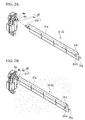
- FIG. 2A is a perspective view when the drive flap member 31 and the actuator 4 are viewed from the side in which the engine room side is arranged, and is a perspective view in a state where the drive flap member 31 and the actuator 4 are disassembled.
- FIG. 2B is a perspective view showing a state where the drive flap member 31 and the actuator 4 are connected to each other.
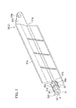
- FIG. 3 is a perspective view when the drive flap member 31 is viewed from the side in which the actuator 4 is arranged.
- the drive flap member 31 includes a flap main body 31a, a first flange 31b, a second flange 31c, breaking portions 31d (refer to FIG. 4 ), reinforcing ribs 31 e, a shaft portion 31f, a support shaft 31g (refer to FIG. 2 ), and a link attachment plate 31h.
- the flap main body 31a is a plate member which is partially bent, and is configured to shield the outside air as a shielding plate.
- the first flange 31b is provided on a side end of the actuator 4 side of the flap main body 31a, and is a disk-shaped portion which is disposed concentrically with the shaft portion 31 f.
- the breaking portions 31d and the reinforcing ribs 31e are supported between the first flange 31b and the second flange 31 c.
- the second flange 31c is disposed to be closer to the actuator 4 than the first flange 31b.
- the second flange 31c supports the breaking portions 31d and the reinforcing ribs 31e between the first flange 31b and the second flange 31c, and supports the shaft portion 31f on the surface of the actuator 4 side.
- FIG. 4 is a view when viewed from A direction of FIG. 3 .
- the first flange 31b and the second flange 31c are omitted.
- each of the breaking portions 31d is a portion having a smaller diameter than that of the shaft portion 31 f.
- the breaking portions 31 are provided between the first flange 31b and the second flange 31c, and are interposed between the flap main body 31 a and the shaft portion 31f.
- each of the breaking portions 31d is set so as to be broken when the actuator 4 attempts to rotate the drive flap member 31 in a case where an abnormal situation, in which foreign substances are stuck on the flap main body 31a or the like and the drive member 31 cannot rotate, occurs. Transmission of torque from the actuator 4 can be stopped by the breaking portions 31d before an excessive load is applied to the actuator 4. Therefore, it is possible to protect the actuator 4.
- the plurality of reinforcing ribs 31e are provided so as to surround the breaking portions 31d, and are provided on the circumferential surfaces of the breaking portions 31d along the breaking portions 31d.
- the reinforcing ribs 31e receive the load acting on the breaking portions 31d in a bending direction. For example, the reinforcing ribs 31e can prevent the breaking portions 31 d from being easily broken when the drive flap member 31 is attached to the actuator 4.
- the shaft portion 31f is provided to protrude from the second flange 31c to the side in which the actuator 4 is arranged.
- the shaft portion 31f includes a plurality of teeth 10 and a notch portion 11 in the circumferential direction when viewed from an attachment direction (that is, the side in which the actuator 4 is arranged) with respect to the actuator 4. More specifically, when viewed from the attachment direction with respect to the actuator 4, the shaft portion 31f includes teeth 10 which are apexes of two squares having the same shapes when the two squares are shifted by 45° and overlap with each other, and the notch portion 11 which is formed by cutting one of the apexes. That is, the shaft portion 31f includes the plurality of (seven) teeth 10 which are arranged at equal intervals in the circumferential direction, and the notch portion 11 which is formed by cutting one of the plurality of teeth 10.
- each of the teeth 10 is viewed from the attachment direction with respect to the actuator 4 is a rectangular isosceles triangle which is formed by perpendicularly connecting two sides.
- the teeth 10 engage with teeth 20 which are provided in a fitting hole 4c described below of the actuator 4, and transmit the rotary power generated by the actuator 4 to the drive flap member 31.
- the shape of the shaft portion 31f when viewed from the attachment direction with respect to the actuator 4 is rotationally asymmetrical.
- the notch portion 11 is disposed at a position at which the notch portion 11 overlaps an embedded portion 21 provided on the fitting hole 4c.
- the notch portion 11 is provided at the position immediately below when the drive flap member 31 is positioned at the closed position.
- the position, at which the notch portion 11 is provided is a position which overlaps with one of the reinforcing ribs 31e when viewed from the attachment direction of the shaft portion 31f with respect to the actuator 4. That is, one of the reinforcing ribs 31e is disposed so as to overlap with the notch portion 11 when viewed from the attachment direction of the shaft portion 31f with respect to the actuator 4.
- the shaft portion 31f having the above-described shape can be molded using two molds 200 without requiring a slide mold. Accordingly, it is possible to easily form the shaft portion 31 f using injection molding.
- the support shaft 31g and the link attachment plate 31h are provided on the end portion opposite to the shaft portion 31f of the flap main body 31a.
- the support shaft 31g is a pin-shaped portion which protrudes from the flap main body 31a toward the lateral side, and is inserted into the shaft hole 2c of the support column 2b.
- the link attachment plate 31h is a plate member which protrudes from the flap main body 31a toward the engine room side, and an attachment hole 31h1 which is configured to attach the link member 5 is provided on the link attachment plate 31h.
- FIG. 6 is an enlarged view of the main portion of the actuator 4.
- the actuator 4 includes a bearing 4a ( FIGS. 2A and 2B ), and an attachment portion 4b.
- the bearing 4a rotatably supports the attachment portion 4b.
- the attachment portion 4b includes the fitting hole 4c into which the shaft portion 31f of the drive flap member 31 is fitted.
- the fitting hole 4c is formed in a shape which includes the plurality of teeth 20 and the embedded portion 21 in the circumferential direction when viewed from the attachment direction (the side in which drive flap member 31 is arranged). More specifically, similarly to the shaft portion 31f, when viewed from the attachment direction with respect to the actuator 4, the fitting hole 4c includes teeth grooves which are apexes of two squares having the same shapes when the two squares are shifted by 45° and overlap each other, and the embedded portion 21 which is formed by embedding one of the apexes.
- the fitting hole 4c includes the plurality of teeth 20 which are arranged at equal intervals in the circumferential direction, and the embedded portion 21 which is formed by embedding one of the teeth grooves.
- the fitting hole 4c is formed so that the shape formed by the inner wall surfaces of the fitting hole 4c when viewed from the insertion direction of the shaft portion 31f is slightly larger than the outer shape of the shaft portion 31 when viewed from the insertion direction of the shaft portion 31f, and in FIG. 6 , the shape of the fitting hole 4c is similar to the outer shape of the shaft portion 31 when viewed from the insertion direction of the shaft portion 31f.
- each of teeth 20 when viewed from the attachment direction of the drive flap member 31 is a rectangular isosceles triangle which is formed by perpendicularly connecting two sides.
- the teeth 20 engage with the teeth 10 of the shaft portion 31f, and transmit the rotary power generated by the actuator 4 to the drive flap member 31.
- the embedded portion 21 is a portion which opposes the notch portion 11 of the shaft portion 31f.
- the embedded portion 21 interferes with the teeth 10 of the shaft portion 31f. Therefore, entering of the shaft portion 31f into the fitting hole 4c is prevented.
- the embedded portion 21 is provided at the position at which the position of the attachment portion 4b is immediately below when the drive flap member 31 is positioned at the closed position.
- the shaft portion 31f of the drive flap member 31 and the fitting hole 4c of the actuator 4 configure an attachment position regulation mechanism 30.
- the drive flap member 31 When the drive flap member 31 is attached to the fitting hole 4c, only in the case where the position of the drive flap member 31 is positioned at the regular position, the drive flap member 31 can be attached to the actuator 4 by the attachment position regulation mechanism 30.
- the attachment portion 4b of the actuator 4 is positioned.
- the attachment portion 4b is positioned so that the embedded portion 21 is positioned immediately below. Accordingly, the regular position of the drive flap member 31 with respect to the actuator 4 is the position at which the notch portion 11 is positioned immediately below, that is, the closed position.
- the shaft portion 31f of the drive flap member 31 is inserted into the fitting hole 4c of the attachment portion 4b of the actuator 4.
- the position of the attachment portion 4b is set so that the embedded portion 21 is positioned immediately the below, if the drive flap member 31 is not positioned at the closed position, the drive flap member 31 cannot be attached to the actuator 4. Accordingly, an operator inserts the shaft portion 31f into the fitting hole 4c so that the notch portion 11 is disposed immediately the below, with the notch portion 11 of the shaft portion 31f as a mark.
- the vehicle grill shutter 1 of the present embodiment it is possible to attach the drive flap member 31 to the actuator 4 only when the drive flap member 31 is positioned at the regular position with respect to the actuator 4 by the attachment position regulation mechanism 30 which includes the shaft portion 31f of the drive flap member 31 and the fitting hole 4c of the actuator 4. Accordingly, it is possible to prevent the operator from incorrectly setting the attachment position of the drive flap member 31 with respect to the actuator 4, and it is possible to prevent erroneous assembly of the drive flap member 31 with respect to the actuator 4.
- the attachment position regulation mechanism 30 includes the shaft portion 31f which is provided on the drive flap member 31 and in which the shape when viewed from the attachment direction is rotationally asymmetrical, and a fitting hole 4c which is provided on the actuator 4 and to which the shaft portion 31f is fitted. According to the vehicle grill shutter 1 of the present embodiment, it is possible to prevent erroneous assembly of the drive flap member 31 with respect to the actuator 4 with a simple structure.
- the shaft portion 31 f includes a plurality of teeth 10 which are arranged at equal intervals in the circumferential direction and the notch portion 11 which is formed by cutting one of the plurality of teeth 10, and is formed in a rotationally asymmetrical shape.
- the operator can confirm the position of the shaft portion 31f, that is, the position of the drive flap member 31 while visually confirming the position of the notch portion 11. Therefore, it is possible to simplify the attachment operation of the drive flap member 31.
- the shape of the shaft portion 31f is rotationally asymmetrical
- an effective contact area of the torque transmission between the shaft portion 31f and the attachment portion 4b decreases as the number of teeth 10 decreases. Accordingly, preferably, the number of the notch portions 11 is one.
- the reinforcing ribs 31e are provided on the circumferential surfaces of the breaking portions 31d.
- the breaking portions 31 d are substantially thickened at the positions at which the reinforcing ribs 31e are provided. Therefore, the torsional stiffness also increases.
- the breaking portions 31d are required to be twisted off when excessive torque acts on the actuator.
- the reinforcing ribs 31e are disposed to overlap with the notch portion 11 when the shaft portion 31f is viewed from the attachment direction.
- the reinforcing ribs 31e are the teeth 10, it is possible to dispose the reinforcing ribs 31e at positions far from the teeth 10 to which the strong torque is applied by disposing the reinforcing ribs 31 e so as to overlap with the notch portion 11. Accordingly, it is possible to dispose the locations, at which the reinforcing ribs 31 are provided and the torsional stiffness increases, so as to be far from the teeth 10 to which strong torque is applied. Therefore, it is possible to assure the twisting off of the breaking portions 31d when excessive torque is applied.
- FIG. 7 is a side view when the drive flap member 31 included in a vehicle grill shutter in the present embodiment is viewed from the attachment direction of the shaft portion 31f.
- the notch portion 11 is provided so as to be positioned immediately below when the drive flap member 31 is positioned at the closed position. However, as shown in FIG. 7 , in the present embodiment, the notch portion 11 is provided at the position horizontally separated from the center of the shaft portion 31f.
- the drive flap member 31 When the drive flap member 31 is positioned at the closed position, the drive flap member 31 receives the highest wind pressure from the front side (left side in FIG. 7 ) in the vehicle toward the rear side (right side in FIG. 7 ).
- the notch portion 11 since the notch portion 11 is provided at the position horizontally separated from the center of the shaft portion 31f when the drive flap member 31 is positioned at the closed position, the notch portion 11 is not disposed immediately above and immediately below. Accordingly, the teeth 10 are disposed immediately above and immediately below, and it is possible to receive the wind pressure with the teeth 10.
- FIGS. 2 and 8 to 11 a third embodiment of the present invention will be described with reference to FIGS. 2 and 8 to 11 .
- descriptions with respect to the portions similar to those of the first embodiment are omitted or simplified.
- FIG. 8 is an enlarged perspective view of the shaft portion 31f included in the drive flap member 31.
- the drive flap member 31 includes vibration preventing ribs 31i (interposing portions).
- each of the vibration preventing ribs 31i is a protrusion which is provided integrally with the teeth 10 of the shaft portion 31f which has the plurality of teeth 10 in the circumferential direction and is formed in a gear shape.
- the protrusion protrudes from the surface of the tooth 10 toward the outside in the radial direction.
- the section of each of the vibration preventing ribs 31i is formed in an approximately semicircular shape and extends in the direction along the axial center of the shaft portion 31f.
- the tip portion of the vibration prevention rib 31i has a shape which is pointed toward the tip side (that is, actuator 4 side) of the shaft portion 31f.
- FIG. 9 is a section view of a region which is not the tip portion of the vibration preventing rib 31i.
- a curvature radius of an apex 31i1 with respect to rising portions 31i2 increases and the apex 31i1 is flattened.
- the apex 31i1 comes into contact with the inner wall surface of the fitting hole 4c.
- the curvature radius of the apex 31i1 may be set to infinity.
- the vibration preventing rib 31i is set with respect to each of the teeth 10. Moreover, the vibration preventing rib 31i is set to each of both sides of the tooth 10 in the circumferential direction of the shaft portion 31f (refer to FIG. 11 ).
- the vibration preventing rib 31i is interposed between the shaft portion 31f and the inner wall surface of the fitting hole 4c. That is, when the shaft portion 31f is fitted into the fitting hole 4c of the actuator 4, the vibration preventing rib 31i fills a gap which is formed between the shaft portion 31f and the inner wall surface of the fitting hole 4c, and prevents the shaft portion 31f from being changed (vibrated) by the fitting hole 4c.
- FIG. 10 is a schematic view including the shaft portion 31f and the vibration preventing ribs 31i.
- the vibration preventing ribs 31i are interposed between the shaft portion 31f and the inner wall surface of the fitting hole 4c. Accordingly, the gap which is formed between the shaft portion 31f and the inner wall surface of the fitting hole 4c is filled by the vibration preventing ribs 31 i, and the vibration of the shaft portion 31f in the fitting hole 4c is prevented. Therefore, according to the vehicle grill shutter 1 of the present embodiment, the variation of the shaft portion 31f with respect to the fitting hole 4c is prevented, and it is possible to prevent the occurrence of noise or the like. In addition, it is possible to correctly transmit the driving force of the actuator 4 to the drive flap member 31 through the vibration preventing ribs 31 i.
- the shaft portion 31f is formed in a gear shape including the plurality of teeth 10 arranged in the circumferential direction, and the vibration preventing ribs 31i is provided on both sides of each of the teeth 10. Accordingly, even when the shaft portion 31f rotates to any side in the circumferential direction, it is possible to cause the vibration preventing ribs 31 i to correctly come into contact with the inner wall surface of the fitting hole 4c. For example, when the shaft portion 31f rotates to the right, the vibration preventing ribs 31i disposed on the right sides of the teeth 10 are strongly pressed to the inner wall surface of the fitting hole 4c.
- the vibration preventing ribs 31i disposed on the left sides of the teeth 10 are strongly pressed to the inner wall surface of the fitting hole 4c. Accordingly, even when the shaft portion 31f rotates to any side in the circumferential direction, the vibration of the shaft portion 31f is prevented, and it is possible to prevent the occurrence of noise or the like. In addition, it is possible to correctly transmit the driving force of the actuator 4 to the drive flap member 31 through the vibration preventing ribs 31i.
- the vibration preventing ribs 31 i are configured of the protrusions which are provided integrally with the teeth 10 of the shaft portion 31f. Accordingly, it is not necessary to form the vibration preventing ribs 31 as independent components, and unlike in a case where the vibration preventing ribs 31i are formed as independent components, it is possible to decrease the number of components of the vehicle grill shutter 1.
- the vibration preventing ribs 311i are provided with respect to each of the teeth 10.
- the notch portion 11 which is formed by cutting one of the plurality of teeth 10 is provided, the load to be applied to the cut tooth 10 is applied to the teeth 10 adjacent to the notch portion 11.
- the loads of the teeth 10 adjacent to the notch portion 11 increase compared to other teeth 10. Since the vibration preventing ribs 31i are provided with respect to each of the teeth 10, it is possible to disperse the load received from the fitting hole 4c by using the vibration preventing ribs 31i provided with respect to each of the teeth 10. As a result, it is possible to prevent a locally large stress from being applied to the teeth 10 adjacent to the notch portion 11. Therefore, it is possible to prolong the service life of the drive flap member 31.
- the tip portion of the vibration preventing rib 31i is formed in a pointed shape in which the height of the vibration preventing rib 31i gradually decreases from the surface of the tooth 10 toward the tip of the shaft portion 31f. Accordingly, when the shaft portion 31f is inserted into the fitting hole 4c, it is possible to prevent the vibration preventing ribs 31i from being hooked to the edge of the fitting hole 4c, and it is possible to easily perform an assembly operation.
- the vibration preventing rib 31i includes the apex 31i1 which comes into contact with the inner wall surface of the fitting hole 4c, and the apex 31i1 is flattened.
- the apex 31i1 is formed having the same curvature radius as the rising portion 31i2
- the contact range between the vibration preventing rib 31i and the inner wall surface of the fitting hole 4c decreases greatly.
- the apex 31i1 of the vibration preventing rib 31i is flattened, the contact area between the vibration preventing rib 31i and the inner wall surface of the fitting hole 4c becomes very large. Accordingly, it is possible to correctly transmit the driving force of the actuator 4 to the drive flap member 31 through the vibration preventing ribs 31i.
- the example in which the shaft portion 31f includes the plurality of teeth 10 arranged at equal intervals in the circumferential direction, and the notch portion 11 which is formed by cutting one of the plurality of teeth 10, and is formed in a rotationally asymmetrical shape.
- the present invention is not limited to this, and a shaft portion having other rotationally asymmetrical shapes may be adopted.
- the example is described, in which in the shaft portion 31f, the squares having the same shapes are shifted by 45° and overlap with each other and one apex is cut.
- the present invention is not limited to this. That is, a shape may be adopted in which equilateral triangles having the same shapes are shifted by 180° and overlap with each other, and one apex is cut.
- the vibration preventing ribs 31i are used as the interposing portions of the present invention.
- the present invention is not limited to this, and an interposing portion having a shape different from the vibration preventing rib 31i may be adopted.
- a hemispherical protrusion or the like may be used as the interposing portion.
- the interposing portion may be formed of a part separated from the shaft portion 31f.
- an annular interposing portion may be attached to the periphery of the shaft portion 31f.
- the vibration preventing ribs 31i are provided integrally with the shaft portion 31f.
- the present invention is not limited to this.
- a configuration may be adopted, in which vibration preventing ribs 4d (interposing portions) are provided with respect to the inner wall surface of the fitting hole 4c.
- the shape of the vibration preventing rib 31i may be a shape in which the height gradually decreases toward the tip over the entire region in the axial center direction of the shaft portion 31f.
- the configuration is adopted, in which the shaft portion 31f is provided on the drive flap member 31 and the fitting hole 4c is provided in the actuator 4.
- the present invention is not limited to this, a configuration may be adopted, in which the fitting hole is provided in the drive flap member and the shaft portion is provided on the actuator.
Landscapes
- Engineering & Computer Science (AREA)
- Chemical & Material Sciences (AREA)
- Combustion & Propulsion (AREA)
- Transportation (AREA)
- Mechanical Engineering (AREA)
- Cooling, Air Intake And Gas Exhaust, And Fuel Tank Arrangements In Propulsion Units (AREA)
- Body Structure For Vehicles (AREA)
Abstract
Description
- The present invention relates to a vehicle grill shutter, a vehicle flap member, and an actuator.
- In recent years, in order to improve fuel consumption performance of a vehicle, or the like, a vehicle grill shutter may be provided in a grill opening portion. For example, as disclosed in Patent Document 1, a vehicle grill shutter includes an actuator, a plurality of flap members, and a link member by which the flap members are connected to each other, in which all flap members are interlocked by rotating some flap members using the actuator.
- [Patent Document 1] Japanese Unexamined Patent Application First Publication No.
2013-199178 - When the vehicle grill shutter is assembled, an operation which attaches the flap member to the actuator is performed. In this case, when an operator incorrectly sets an attachment position of the flap member with respect to the actuator, the position of the flap member is always deviated from the original position in the assembled vehicle grill shutter. Accordingly, for example, even when the flap member is controlled so as to be completely closed, the flap member does not reach a completely closed position. Therefore, improvement of sufficient fuel consumption performance may not be achieved.
- In addition, generally, connection between the actuator and the flap member is performed by fitting a shaft portion provided on one of the actuator and the flap member to a fitting hole provided on the other of the actuator and the flap member. However, if a slight gap exists between the shaft portion and the inner wall surface of the fitting hole, the shaft portion vibrates in the fitting hole due to vibration generated when the position of the flap member is changed or when a vehicle travels, or the like. Accordingly, the adjacent flap members are rattled, and noise or the like occurs. In addition, when the flap member rotates, the contact range between the shaft portion and the fitting hole decreases, and a driving force of the actuator may not be correctly transmitted to the flap member.
- The present invention is made in consideration of the above-described problems, and an object thereof is to prevent erroneous assembly of the flap member with respect to the actuator in a vehicle grill shutter and a vehicle flap member.
- In addition, another object of the present invention is to prevent he shaft portion from vibrating in the fitting hole, prevent occurrence of noise or the like, and correctly transmit the driving force of the actuator to the flap member, in the vehicle grill shutter in which the shaft portion is fitted to the fitting hole and the flap member and the actuator are connected to each other.
- The present invention adopts the following configurations to achieve the above-described objects.
- A vehicle grill shutter according to a first aspect of the present invention, includes: an actuator; a flap member which is configured to rotate between a closed position and an open position by the actuator; and an attachment position regulation mechanism which is configured to connect the actuator and the flap member only when the flap member is positioned at a regular position with respect to the actuator.
- The attachment position regulation mechanism may include a shaft portion which is provided on one of the actuator and the flap member, and has a rotationally asymmetrical shape when viewed from an attachment direction, and an attachment portion having a fitting hole which is provided on the other of the actuator and the flap member and to which the shaft portion is fitted.
- The shaft portion may include a plurality of teeth which are arranged at equal intervals in a circumferential direction, and a notch portion which is formed by notching at least one of the plurality of teeth.
- The flap member may include a flap main body, the shaft portion, a breaking portion which is interposed between the flap main body and the shaft portion and has a smaller diameter than a diameter of the shaft portion, and a reinforcing rib which is provided along the breaking portion with respect to a circumferential surface of the breaking portion, in which the reinforcing rib may be disposed to overlap with the notch portion of the shaft portion when viewed from the attachment direction.
- The notch portion may be disposed at a position at which the notch portion is horizontally separated from a center of the shaft portion when the flap member is positioned at the closed position.
- A vehicle flap member according to a second aspect of the present invention is rotated between a closed position and an open position by an actuator, and includes a shaft portion or an attachment portion having a fitting hole in which a shape is rotationally asymmetrical when viewed from an attachment direction, as a connection portion between the vehicle flap member and the actuator.
- A vehicle grill shutter according to a third aspect of the present invention, includes: an actuator; a flap member in which a position is changed between a closed position and an open position by the actuator; a shaft portion which is provided on one of the actuator and the flap member; an attachment portion having a fitting hole which is provided on the other of the actuator and the flap member, and into which the shaft portion is fitted; and an interposing portion which is interposed between the shaft portion and an inner wall surface of the fitting hole.
- The shaft portion may have a gear shape which includes a plurality of teeth arranged in a circumferential direction, and the interposing portion may be formed by a protrusion which is provided integrally with the tooth on both sides of the tooth in the circumferential direction of the shaft portion.
- A notch portion which is formed by notching at least one of the plurality of teeth may be provided, and the protrusion may be provided with respect to each of the teeth.
- The protrusion may extend in a direction along an axial center of the shaft portion, and a height of the protrusion from the surface of the tooth may decrease toward a tip of the shaft portion.
- The protrusion may include an apex which is configured to come into contact with an inner wall surface of the fitting hole, and the apex may be flattened.
- In a vehicle flap member according to a fourth aspect of the present invention, a position of the vehicle flap member is changed between a closed position and an open position by an actuator, and the vehicle flap member includes: a shaft portion which is fitted into a fitting hole provided in the actuator; and an interposing portion which is interposed between the shaft portion and the fitting hole.
- In a vehicle flap member according to a fifth aspect of the present invention, a position of the vehicle flap member is changed between a closed position and an open position by an actuator, and the vehicle flap member includes: an attachment portion having a fitting hole into which a shaft portion provided in the actuator is fitted; and an interposing portion which is interposed between the shaft portion and the fitting hole.
- An actuator according to a sixth aspect of the present invention, includes: a shaft portion which is fitted into a fitting hole provided in the vehicle flap member; and an interposing portion which is interposed between the shaft portion and the fitting hole.
- An actuator according to a seventh aspect of the present invention, includes: an attachment portion having a fitting hole into which a shaft portion provided in the vehicle flap member is fitted; and an interposing portion which is interposed between the shaft portion and the fitting hole.
- According to the aspects of the present invention, it is possible to attach the flap member to the actuator only at a regular position with respect to the actuator by the attachment position regulation member. Accordingly, it is possible to prevent an operator from incorrectly setting the attachment position of the flap member with respect to the actuator, and it is possible to prevent erroneous assembly of the flap member with respect to the actuator in the vehicle grill shutter and the vehicle flap member.
- In addition, according to the aspects of the present invention, the interposing portion is provided, which is interposed between the shaft portion which is provided on one of the actuator and the flap member and the inner wall surface of the fitting hole which is provided on the other of the actuator and the flap member. The interposing portion is interposed between the shaft portion and the inner wall surface of the fitting hole. Therefore, it is possible to prevent vibration of the shaft portion with respect to the fitting hole. Therefore, according to the aspects of the present invention, in the vehicle grill shutter in which the flap member and the actuator are connected to each other by fitting the shaft portion into the fitting hole, it is possible to prevent the shaft portion from vibrating in the fitting hole, and it is possible to prevent the occurrence of noise or the like. In addition, it is possible to correctly transmit a driving force of the actuator to the flap member through the interposing portion.
-
-
FIG. 1 is an exploded perspective view of a vehicle grill shutter in a first embodiment of the present invention and is a perspective view showing a front portion of a vehicle. -
FIG. 2A is a perspective view when a drive flap member and an actuator included in a vehicle grill shutter in the first embodiment of the present invention are viewed from the side in which an engine room is arranged, and shows a state where the drive flap member and the actuator are disassembled. -
FIG. 2B is a perspective view when the drive flap member and the actuator included in the vehicle grill shutter in the first embodiment of the present invention are viewed from the side in which an engine room is arranged, and shows a state where the drive flap member and the actuator are connected to each other. -
FIG. 3 is a perspective view when the drive flap member included in the vehicle grill shutter in the first embodiment of the present invention is viewed from in which the actuator side is arranged. -
FIG. 4 is a view when viewed from A direction ofFIG. 3 . -
FIG. 5 is a schematic view for explaining a method of molding a shaft portion included in the vehicle grill shutter in the first embodiment of the present invention. -
FIG. 6 is an enlarged view of the main portion of the actuator included in the vehicle grill shutter in the first embodiment of the present invention. -
FIG. 7 is a side view when a drive flap member included in a vehicle grill shutter in a second embodiment of the present invention is viewed from an attachment direction of a shaft portion. -
FIG. 8 is an enlarged perspective view showing the shaft portion of the drive flap member included in the vehicle grill shutter in a third embodiment of the present invention. -
FIG. 9 is a sectional view of a vibration preventing rib included in the vehicle grill shutter in the third embodiment of the present invention. -
FIG. 10 is a schematic view showing the shaft portion and the vibration preventing rib included in the vehicle grill shutter in the third embodiment of the present invention. -
FIG. 11 is a schematic view showing a shaft portion and a vibration preventing rib included in a modification example of the vehicle grill shutter in the third embodiment of the present invention. - Hereinafter, embodiments with respect to a vehicle grill shutter, a vehicle flap member, and an actuator according to the present invention will be described with reference to the drawings. Moreover, in the following drawings, in order to allow the size of each member to be a recognizable size, the scale of each member is appropriately changed.
-
FIG. 1 is an exploded perspective view of a vehicle grill shutter 1 in a first embodiment of the present invention and is a perspective view showing a front portion of a vehicle. As shown inFIG. 1 , afront bumper 101 is provided on a front surface of avehicle 100 along a vehicle width direction. A grill opening 102 communicating with an engine room is formed on the lower portion side of thefront bumper 101. As shown inFIG. 1 , a vehicle grill shutter 1 is fixed to a vehicle body so as to be disposed inside the grill opening 102. - As shown in
FIG. 1 , the vehicle grill shutter 1 includes aframe 2,flap members 3, anactuator 4, and alink member 5. Theframe 2 includes anouter edge portion 2a which is formed in an approximately rectangular shape when viewed from the front surface of thevehicle 100, and asupport column 2b which vertically extends from the center of theouter edge portion 2a and is attached to theouter edge portion 2a. In theframe 2, a region surrounded by theouter edge portion 2a having an approximately rectangular shape is horizontally divided by thesupport column 2b. For example, theframe 2 is formed of a composite material including a polypropylene resin and glass fibers. - In the region surrounded by the
outer edge portion 2a of theframe 2, three flap members 3 (vehicle flap member) are disposed in each region which is divided by thesupport column 2b. In order to rotatably support theflap members 3, theframe 2 includes a plurality of shaft holes 2c which are provided on the side of thesupport column 2b, and a plurality ofshaft holes 2d which are provided on theouter edge portion 2a. Oneshaft hole 2c and oneshaft hole 2d are provided with respect to the oneflap member 3, and theshaft hole 2c and theshaft hole 2d which support thesame flap member 3 are provided so as to horizontally oppose each other. - Three
flap members 3 are vertically arranged with respect to both the right and left sides of thesupport column 2b, and in the present embodiment, a total of six flap members are provided. Among theflap members 3, oneflap member 3 is adrive flap member 31 which is directly connected to theactuator 4, and the remaining fiveflap members 3 are drivenflap members 32 which are connected to thedrive flap member 31 by thelink member 5. In eachflap member 3, an end portion on one side in the horizontal direction is rotatably supported by theshaft hole 2c provided on thesupport column 2b, and an end portion on the other side is rotatably supported by theshaft hole 2d provided on theouter edge portion 2a. Moreover, theflap members 3 have approximately the same shape, and each of the flap members rotates between a closed position at which a projection area in a movable range is the greatest when the front surface side of thevehicle 100, and an open position at which the projection area is the smallest. In addition, theflap members 3 are provided so that theflap members 3 partially overlap each other in an up-down direction in the case where theflap members 3 are positioned at the closed positions when viewed from the front surface side of thevehicle 100, and outside air is prevented from passing through theouter edge portion 2a of theframe 2 by theflap members 3 positioned at the closed positions. Similarly to theframe 2, for example, each of theflap members 3 is formed of a composite material including a polypropylene resin and glass fibers. - The
drive flap member 31 is theflap member 3 which is disposed at the center among threeflap members 3 vertically arranged on the one side of thesupport column 2b, and power is transmitted from theactuator 4 to thedrive flap member 31. Therefore, thedrive flap member 31 is rotated in a state where both the right and left ends are rotatably supported. Accordingly, the position of thedrive flap member 31 is changed between the closed position and the open position. Theactuator 4 includes a servo motor, a solenoid, or the like as a drive source, and generates power for rotating theflap members 3 according to a control of an engine control unit. In addition, an attachment structure between thedrive flap member 31 and theactuator 4 will be described in detail below. Thelink member 5 connects thedrive flap member 31 and the drivenflap members 32, and transmits the power, which is transmitted from theactuator 4 to thedrive flap member 31, to the drivenflap member 32. Accordingly, the drivenflap members 32 are rotated in synchronization with thedrive flap member 31. - In the vehicle grill shutter 1 according to the present embodiment, the
flap members 3 are positioned at the closed positions by theactuator 4. Therefore, the outside air is prevented from flowing into the flap members through thegrill opening 102. In addition, theflap members 3 are positioned at the open positions by theactuator 4. Therefore, the outside air can flow into the flap members through thegrill opening 102. - In addition, the positions of the
flap members 3 can be arbitrary set between the closed positions and the open positions. In this case, the outside air having a flow rate according to the position (that is, opening degree) of each of theflap members 3 can flow into the flap member through thegrill opening 102. - Subsequently, the attachment structure between the
drive flap member 31 and theactuator 4 will be described.FIG. 2A is a perspective view when thedrive flap member 31 and theactuator 4 are viewed from the side in which the engine room side is arranged, and is a perspective view in a state where thedrive flap member 31 and theactuator 4 are disassembled.FIG. 2B is a perspective view showing a state where thedrive flap member 31 and theactuator 4 are connected to each other. In addition,FIG. 3 is a perspective view when thedrive flap member 31 is viewed from the side in which theactuator 4 is arranged. - As shown in
FIG. 3 , thedrive flap member 31 includes a flapmain body 31a, afirst flange 31b, asecond flange 31c, breakingportions 31d (refer toFIG. 4 ), reinforcingribs 31 e, ashaft portion 31f, asupport shaft 31g (refer toFIG. 2 ), and alink attachment plate 31h. - The flap
main body 31a is a plate member which is partially bent, and is configured to shield the outside air as a shielding plate. Thefirst flange 31b is provided on a side end of theactuator 4 side of the flapmain body 31a, and is a disk-shaped portion which is disposed concentrically with theshaft portion 31 f. The breakingportions 31d and the reinforcingribs 31e are supported between thefirst flange 31b and thesecond flange 31 c. Thesecond flange 31c is disposed to be closer to theactuator 4 than thefirst flange 31b. Thesecond flange 31c supports the breakingportions 31d and the reinforcingribs 31e between thefirst flange 31b and thesecond flange 31c, and supports theshaft portion 31f on the surface of theactuator 4 side. -
FIG. 4 is a view when viewed from A direction ofFIG. 3 . In addition, inFIG. 4 , in order to provide easy visual confirmation with respect to relationships between theshaft portion 31f and the reinforcingribs 31e, thefirst flange 31b and thesecond flange 31c are omitted. As shown inFIG. 4 , each of the breakingportions 31d is a portion having a smaller diameter than that of theshaft portion 31 f. The breakingportions 31 are provided between thefirst flange 31b and thesecond flange 31c, and are interposed between the flapmain body 31 a and theshaft portion 31f. The strength of each of the breakingportions 31d is set so as to be broken when theactuator 4 attempts to rotate thedrive flap member 31 in a case where an abnormal situation, in which foreign substances are stuck on the flapmain body 31a or the like and thedrive member 31 cannot rotate, occurs. Transmission of torque from theactuator 4 can be stopped by the breakingportions 31d before an excessive load is applied to theactuator 4. Therefore, it is possible to protect theactuator 4. As shown inFIG. 4 , the plurality of reinforcingribs 31e are provided so as to surround thebreaking portions 31d, and are provided on the circumferential surfaces of the breakingportions 31d along the breakingportions 31d. The reinforcingribs 31e receive the load acting on the breakingportions 31d in a bending direction. For example, the reinforcingribs 31e can prevent the breakingportions 31 d from being easily broken when thedrive flap member 31 is attached to theactuator 4. - The
shaft portion 31f is provided to protrude from thesecond flange 31c to the side in which theactuator 4 is arranged. Theshaft portion 31f includes a plurality ofteeth 10 and anotch portion 11 in the circumferential direction when viewed from an attachment direction (that is, the side in which theactuator 4 is arranged) with respect to theactuator 4. More specifically, when viewed from the attachment direction with respect to theactuator 4, theshaft portion 31f includesteeth 10 which are apexes of two squares having the same shapes when the two squares are shifted by 45° and overlap with each other, and thenotch portion 11 which is formed by cutting one of the apexes. That is, theshaft portion 31f includes the plurality of (seven)teeth 10 which are arranged at equal intervals in the circumferential direction, and thenotch portion 11 which is formed by cutting one of the plurality ofteeth 10. - The shape when each of the
teeth 10 is viewed from the attachment direction with respect to theactuator 4 is a rectangular isosceles triangle which is formed by perpendicularly connecting two sides. Theteeth 10 engage withteeth 20 which are provided in afitting hole 4c described below of theactuator 4, and transmit the rotary power generated by theactuator 4 to thedrive flap member 31. - Due to the
notch portion 11, the shape of theshaft portion 31f when viewed from the attachment direction with respect to theactuator 4 is rotationally asymmetrical. When theshaft portion 31f is fitted to thefitting hole 4c described below of theactuator 4 at a regular position, thenotch portion 11 is disposed at a position at which thenotch portion 11 overlaps an embeddedportion 21 provided on thefitting hole 4c. - In the present embodiment, as shown in
FIG. 3 , thenotch portion 11 is provided at the position immediately below when thedrive flap member 31 is positioned at the closed position. As shown inFIG. 4 , the position, at which thenotch portion 11 is provided, is a position which overlaps with one of the reinforcingribs 31e when viewed from the attachment direction of theshaft portion 31f with respect to theactuator 4. That is, one of the reinforcingribs 31e is disposed so as to overlap with thenotch portion 11 when viewed from the attachment direction of theshaft portion 31f with respect to theactuator 4. - In addition, for example, as shown in
FIG. 5 , theshaft portion 31f having the above-described shape can be molded using two molds 200 without requiring a slide mold. Accordingly, it is possible to easily form theshaft portion 31 f using injection molding. - The
support shaft 31g and thelink attachment plate 31h are provided on the end portion opposite to theshaft portion 31f of the flapmain body 31a. Thesupport shaft 31g is a pin-shaped portion which protrudes from the flapmain body 31a toward the lateral side, and is inserted into theshaft hole 2c of thesupport column 2b. Thelink attachment plate 31h is a plate member which protrudes from the flapmain body 31a toward the engine room side, and an attachment hole 31h1 which is configured to attach thelink member 5 is provided on thelink attachment plate 31h. -
FIG. 6 is an enlarged view of the main portion of theactuator 4. Theactuator 4 includes abearing 4a (FIGS. 2A and 2B ), and anattachment portion 4b. Thebearing 4a rotatably supports theattachment portion 4b. - The
attachment portion 4b includes thefitting hole 4c into which theshaft portion 31f of thedrive flap member 31 is fitted. Thefitting hole 4c is formed in a shape which includes the plurality ofteeth 20 and the embeddedportion 21 in the circumferential direction when viewed from the attachment direction (the side in which driveflap member 31 is arranged). More specifically, similarly to theshaft portion 31f, when viewed from the attachment direction with respect to theactuator 4, thefitting hole 4c includes teeth grooves which are apexes of two squares having the same shapes when the two squares are shifted by 45° and overlap each other, and the embeddedportion 21 which is formed by embedding one of the apexes. Thefitting hole 4c includes the plurality ofteeth 20 which are arranged at equal intervals in the circumferential direction, and the embeddedportion 21 which is formed by embedding one of the teeth grooves. In order to insert theshaft portion 31 f into thefitting hole 4c, thefitting hole 4c is formed so that the shape formed by the inner wall surfaces of thefitting hole 4c when viewed from the insertion direction of theshaft portion 31f is slightly larger than the outer shape of theshaft portion 31 when viewed from the insertion direction of theshaft portion 31f, and inFIG. 6 , the shape of thefitting hole 4c is similar to the outer shape of theshaft portion 31 when viewed from the insertion direction of theshaft portion 31f. - The shape of each of
teeth 20 when viewed from the attachment direction of thedrive flap member 31 is a rectangular isosceles triangle which is formed by perpendicularly connecting two sides. Theteeth 20 engage with theteeth 10 of theshaft portion 31f, and transmit the rotary power generated by theactuator 4 to thedrive flap member 31. The embeddedportion 21 is a portion which opposes thenotch portion 11 of theshaft portion 31f. - When the
drive flap member 31 is attached to thefitting hole 4c, in a case where the position of thedrive flap member 31 is not positioned at the regular position (that is, thenotch portion 11 is not positioned immediately below), the embeddedportion 21 interferes with theteeth 10 of theshaft portion 31f. Therefore, entering of theshaft portion 31f into thefitting hole 4c is prevented. In the present embodiment, the embeddedportion 21 is provided at the position at which the position of theattachment portion 4b is immediately below when thedrive flap member 31 is positioned at the closed position. - Moreover, in the vehicle grill shutter 1 according to the present embodiment, the
shaft portion 31f of thedrive flap member 31 and thefitting hole 4c of theactuator 4 configure an attachmentposition regulation mechanism 30. - When the
drive flap member 31 is attached to thefitting hole 4c, only in the case where the position of thedrive flap member 31 is positioned at the regular position, thedrive flap member 31 can be attached to theactuator 4 by the attachmentposition regulation mechanism 30. - When the vehicle grill shutter 1 is assembled, in the case where the
drive flap member 31 is attached to theactuator 4, first, theattachment portion 4b of theactuator 4 is positioned. Here, theattachment portion 4b is positioned so that the embeddedportion 21 is positioned immediately below. Accordingly, the regular position of thedrive flap member 31 with respect to theactuator 4 is the position at which thenotch portion 11 is positioned immediately below, that is, the closed position. - Subsequently, the
shaft portion 31f of thedrive flap member 31 is inserted into thefitting hole 4c of theattachment portion 4b of theactuator 4. In this case, since the position of theattachment portion 4b is set so that the embeddedportion 21 is positioned immediately the below, if thedrive flap member 31 is not positioned at the closed position, thedrive flap member 31 cannot be attached to theactuator 4. Accordingly, an operator inserts theshaft portion 31f into thefitting hole 4c so that thenotch portion 11 is disposed immediately the below, with thenotch portion 11 of theshaft portion 31f as a mark. In this way, according to the vehicle grill shutter 1 of the present embodiment, it is possible to attach thedrive flap member 31 to theactuator 4 only when thedrive flap member 31 is positioned at the regular position with respect to theactuator 4 by the attachmentposition regulation mechanism 30 which includes theshaft portion 31f of thedrive flap member 31 and thefitting hole 4c of theactuator 4. Accordingly, it is possible to prevent the operator from incorrectly setting the attachment position of thedrive flap member 31 with respect to theactuator 4, and it is possible to prevent erroneous assembly of thedrive flap member 31 with respect to theactuator 4. - Moreover, in the vehicle grill shutter 1 according to the present embodiment, the attachment
position regulation mechanism 30 includes theshaft portion 31f which is provided on thedrive flap member 31 and in which the shape when viewed from the attachment direction is rotationally asymmetrical, and afitting hole 4c which is provided on theactuator 4 and to which theshaft portion 31f is fitted. According to the vehicle grill shutter 1 of the present embodiment, it is possible to prevent erroneous assembly of thedrive flap member 31 with respect to theactuator 4 with a simple structure. - In addition, in the vehicle grill shutter 1 according to the present embodiment, the
shaft portion 31 f includes a plurality ofteeth 10 which are arranged at equal intervals in the circumferential direction and thenotch portion 11 which is formed by cutting one of the plurality ofteeth 10, and is formed in a rotationally asymmetrical shape. Moreover, according to the vehicle grill shutter 1 of the present embodiment, the operator can confirm the position of theshaft portion 31f, that is, the position of thedrive flap member 31 while visually confirming the position of thenotch portion 11. Therefore, it is possible to simplify the attachment operation of thedrive flap member 31. In addition, for example, on the premise that the shape of theshaft portion 31f is rotationally asymmetrical, it is also possible to form the plurality ofnotch portions 11 by cutting two or more teeth among theteeth 10. However, an effective contact area of the torque transmission between theshaft portion 31f and theattachment portion 4b decreases as the number ofteeth 10 decreases. Accordingly, preferably, the number of thenotch portions 11 is one. - Moreover, in the vehicle grill shutter 1 according to the present embodiment, in order to prevent the breaking
portions 31 d from being broken during the attachment operation of thedrive flap member 31 or the like, the reinforcingribs 31e are provided on the circumferential surfaces of the breakingportions 31d. The breakingportions 31 d are substantially thickened at the positions at which the reinforcingribs 31e are provided. Therefore, the torsional stiffness also increases. However, in order to protect theactuator 4 as described above, the breakingportions 31d are required to be twisted off when excessive torque acts on the actuator. With respect to this, in the vehicle grill shutter 1 according to the present embodiment, the reinforcingribs 31e are disposed to overlap with thenotch portion 11 when theshaft portion 31f is viewed from the attachment direction. Since the locations to which strong torque is applied in theshaft portion 31f are theteeth 10, it is possible to dispose the reinforcingribs 31e at positions far from theteeth 10 to which the strong torque is applied by disposing the reinforcingribs 31 e so as to overlap with thenotch portion 11. Accordingly, it is possible to dispose the locations, at which the reinforcingribs 31 are provided and the torsional stiffness increases, so as to be far from theteeth 10 to which strong torque is applied. Therefore, it is possible to assure the twisting off of the breakingportions 31d when excessive torque is applied. - Next, a second embodiment of the present invention will be described. In addition, in descriptions of the present embodiment, descriptions with respect to the portions similar to those of the first embodiment are omitted or simplified.
-
FIG. 7 is a side view when thedrive flap member 31 included in a vehicle grill shutter in the present embodiment is viewed from the attachment direction of theshaft portion 31f. In the first embodiment, thenotch portion 11 is provided so as to be positioned immediately below when thedrive flap member 31 is positioned at the closed position. However, as shown inFIG. 7 , in the present embodiment, thenotch portion 11 is provided at the position horizontally separated from the center of theshaft portion 31f. - When the
drive flap member 31 is positioned at the closed position, thedrive flap member 31 receives the highest wind pressure from the front side (left side inFIG. 7 ) in the vehicle toward the rear side (right side inFIG. 7 ). In this case, in the present embodiment, since thenotch portion 11 is provided at the position horizontally separated from the center of theshaft portion 31f when thedrive flap member 31 is positioned at the closed position, thenotch portion 11 is not disposed immediately above and immediately below. Accordingly, theteeth 10 are disposed immediately above and immediately below, and it is possible to receive the wind pressure with theteeth 10. Therefore, compared to the case where thenotch portion 11 is disposed immediately above or immediately below when thedrive flap member 31 is positioned at the closed position, it is possible to improve proof stress in the direction in which the wind pressure is received. In addition, it is possible to prolong the service life of theshaft portion 31f, and it is possible to decrease the frequency of replacement. - Subsequently, a third embodiment of the present invention will be described with reference to
FIGS. 2 and8 to 11 . In addition, in the descriptions of the present embodiment, descriptions with respect to the portions similar to those of the first embodiment are omitted or simplified. -
FIG. 8 is an enlarged perspective view of theshaft portion 31f included in thedrive flap member 31. - As shown in
FIG. 8 , thedrive flap member 31 according to the present embodiment includesvibration preventing ribs 31i (interposing portions). - As shown in
FIG. 8 , each of thevibration preventing ribs 31i is a protrusion which is provided integrally with theteeth 10 of theshaft portion 31f which has the plurality ofteeth 10 in the circumferential direction and is formed in a gear shape. In addition, the protrusion protrudes from the surface of thetooth 10 toward the outside in the radial direction. As shown inFIG. 8 , the section of each of thevibration preventing ribs 31i is formed in an approximately semicircular shape and extends in the direction along the axial center of theshaft portion 31f. In addition, the tip portion of thevibration prevention rib 31i has a shape which is pointed toward the tip side (that is,actuator 4 side) of theshaft portion 31f. That is, the shape of thevibration preventing rib 31i is set so that an amount (height) of the tip portion protruding from thetooth 10 decreases toward the tip.FIG. 9 is a section view of a region which is not the tip portion of thevibration preventing rib 31i. As shown inFIG. 9 , in thevibration preventing rib 31i, a curvature radius of an apex 31i1 with respect to rising portions 31i2 increases and the apex 31i1 is flattened. In thevibration preventing rib 31i, the apex 31i1 comes into contact with the inner wall surface of thefitting hole 4c. In addition, in order to flatten the apex 31i1, the curvature radius of the apex 31i1 may be set to infinity. - Moreover, the
vibration preventing rib 31i is set with respect to each of theteeth 10. Moreover, thevibration preventing rib 31i is set to each of both sides of thetooth 10 in the circumferential direction of theshaft portion 31f (refer toFIG. 11 ). - When the
shaft portion 31f is fitted into thefitting hole 4c of theactuator 4, thevibration preventing rib 31i is interposed between theshaft portion 31f and the inner wall surface of thefitting hole 4c. That is, when theshaft portion 31f is fitted into thefitting hole 4c of theactuator 4, thevibration preventing rib 31i fills a gap which is formed between theshaft portion 31f and the inner wall surface of thefitting hole 4c, and prevents theshaft portion 31f from being changed (vibrated) by thefitting hole 4c. -
FIG. 10 is a schematic view including theshaft portion 31f and thevibration preventing ribs 31i. As shown inFIG. 10 , if theshaft portion 31f of thedrive flap member 31 is fitted into thefitting hole 4c, thevibration preventing ribs 31i are interposed between theshaft portion 31f and the inner wall surface of thefitting hole 4c. Accordingly, the gap which is formed between theshaft portion 31f and the inner wall surface of thefitting hole 4c is filled by thevibration preventing ribs 31 i, and the vibration of theshaft portion 31f in thefitting hole 4c is prevented. Therefore, according to the vehicle grill shutter 1 of the present embodiment, the variation of theshaft portion 31f with respect to thefitting hole 4c is prevented, and it is possible to prevent the occurrence of noise or the like. In addition, it is possible to correctly transmit the driving force of theactuator 4 to thedrive flap member 31 through thevibration preventing ribs 31 i. - Moreover, according to the vehicle grill shutter 1 of the present embodiment, the
shaft portion 31f is formed in a gear shape including the plurality ofteeth 10 arranged in the circumferential direction, and thevibration preventing ribs 31i is provided on both sides of each of theteeth 10. Accordingly, even when theshaft portion 31f rotates to any side in the circumferential direction, it is possible to cause thevibration preventing ribs 31 i to correctly come into contact with the inner wall surface of thefitting hole 4c. For example, when theshaft portion 31f rotates to the right, thevibration preventing ribs 31i disposed on the right sides of theteeth 10 are strongly pressed to the inner wall surface of thefitting hole 4c. In addition, when theshaft portion 31f rotates to the left, thevibration preventing ribs 31i disposed on the left sides of theteeth 10 are strongly pressed to the inner wall surface of thefitting hole 4c. Accordingly, even when theshaft portion 31f rotates to any side in the circumferential direction, the vibration of theshaft portion 31f is prevented, and it is possible to prevent the occurrence of noise or the like. In addition, it is possible to correctly transmit the driving force of theactuator 4 to thedrive flap member 31 through thevibration preventing ribs 31i. - Moreover, in the vehicle grill shutter 1 according to the present embodiment, the
vibration preventing ribs 31 i are configured of the protrusions which are provided integrally with theteeth 10 of theshaft portion 31f. Accordingly, it is not necessary to form thevibration preventing ribs 31 as independent components, and unlike in a case where thevibration preventing ribs 31i are formed as independent components, it is possible to decrease the number of components of the vehicle grill shutter 1. - In addition, in the vehicle grill shutter 1 according to the present embodiment, the vibration preventing ribs 311i are provided with respect to each of the
teeth 10. In the vehicle grill shutter 1 according to the present embodiment, since thenotch portion 11 which is formed by cutting one of the plurality ofteeth 10 is provided, the load to be applied to thecut tooth 10 is applied to theteeth 10 adjacent to thenotch portion 11. - Accordingly, the loads of the
teeth 10 adjacent to thenotch portion 11 increase compared toother teeth 10. Since thevibration preventing ribs 31i are provided with respect to each of theteeth 10, it is possible to disperse the load received from thefitting hole 4c by using thevibration preventing ribs 31i provided with respect to each of theteeth 10. As a result, it is possible to prevent a locally large stress from being applied to theteeth 10 adjacent to thenotch portion 11. Therefore, it is possible to prolong the service life of thedrive flap member 31. - Moreover, in the vehicle grill shutter 1 according to the present embodiment, the tip portion of the
vibration preventing rib 31i is formed in a pointed shape in which the height of thevibration preventing rib 31i gradually decreases from the surface of thetooth 10 toward the tip of theshaft portion 31f. Accordingly, when theshaft portion 31f is inserted into thefitting hole 4c, it is possible to prevent thevibration preventing ribs 31i from being hooked to the edge of thefitting hole 4c, and it is possible to easily perform an assembly operation. - Moreover, in the vehicle grill shutter 1 according to the present embodiment, the
vibration preventing rib 31i includes the apex 31i1 which comes into contact with the inner wall surface of thefitting hole 4c, and the apex 31i1 is flattened. For example, as shown by a virtual line inFIG. 9 , when the apex 31i1 is formed having the same curvature radius as the rising portion 31i2, the contact range between thevibration preventing rib 31i and the inner wall surface of thefitting hole 4c decreases greatly. However, according to the vehicle grill shutter 1 of the present embodiment, since the apex 31i1 of thevibration preventing rib 31i is flattened, the contact area between thevibration preventing rib 31i and the inner wall surface of thefitting hole 4c becomes very large. Accordingly, it is possible to correctly transmit the driving force of theactuator 4 to thedrive flap member 31 through thevibration preventing ribs 31i. - Hereinbefore, preferred embodiments of the present invention are described with reference the accompanying drawings. However, it goes without saying that the present invention is not limited to the embodiments. The shapes of constituent members in the above-described embodiments, combinations thereof, or the like are examples. Therefore, various modifications may be applied based on design requests or the like within a range which does not depart from the gist of the present invention.
- For example, in the above-described embodiments, the example is described, in which the
shaft portion 31f includes the plurality ofteeth 10 arranged at equal intervals in the circumferential direction, and thenotch portion 11 which is formed by cutting one of the plurality ofteeth 10, and is formed in a rotationally asymmetrical shape. However, the present invention is not limited to this, and a shaft portion having other rotationally asymmetrical shapes may be adopted. - In addition, in the above-described embodiment, the example is described, in which in the
shaft portion 31f, the squares having the same shapes are shifted by 45° and overlap with each other and one apex is cut. However, the present invention is not limited to this. That is, a shape may be adopted in which equilateral triangles having the same shapes are shifted by 180° and overlap with each other, and one apex is cut. - In addition, for example, in the third embodiment, the configuration is described, in which the
vibration preventing ribs 31i are used as the interposing portions of the present invention. However, the present invention is not limited to this, and an interposing portion having a shape different from thevibration preventing rib 31i may be adopted. For example, a hemispherical protrusion or the like may be used as the interposing portion. Moreover, the interposing portion may be formed of a part separated from theshaft portion 31f. For example, an annular interposing portion may be attached to the periphery of theshaft portion 31f. - Moreover, in the third embodiment, the configuration in which the
vibration preventing ribs 31i are provided integrally with theshaft portion 31f is described. However, the present invention is not limited to this. For example, as shown inFIG. 11 , a configuration may be adopted, in whichvibration preventing ribs 4d (interposing portions) are provided with respect to the inner wall surface of thefitting hole 4c. By using theactuator 4 including thevibration preventing ribs 4d, it is not necessary to provide thevibration preventing ribs 31i on theshaft portion 31f. - Moreover, in the third embodiment, the configuration in which only the tip portion of the
vibration preventing rib 31i is formed in a pointed shape is adopted. However, the present invention is not limited to this. For example, the shape of thevibration preventing rib 31i may be a shape in which the height gradually decreases toward the tip over the entire region in the axial center direction of theshaft portion 31f. - Moreover, in the above-described embodiment, the configuration is adopted, in which the
shaft portion 31f is provided on thedrive flap member 31 and thefitting hole 4c is provided in theactuator 4. However, the present invention is not limited to this, a configuration may be adopted, in which the fitting hole is provided in the drive flap member and the shaft portion is provided on the actuator. - While preferred embodiments of the invention have been described and illustrated above, it should be understood that these are exemplary of the invention and are not to be considered as limiting. Additions, omissions, substitutions, and other modifications can be made without departing from the scope of the present invention. Accordingly, the invention is not to be considered as being limited by the foregoing description, and is only limited by the scope of the appended claims.
-
- 1... vehicle grill shutter, 3... flap member, 4... actuator, 4a... bearing, 4b... attachment portion, 4c... fitting hole, 5... link member, 10... teeth, 11... notch portion, 20... teeth, 21... embedded portion, 30... attachment position regulation mechanism, 31... drive flap member (vehicle flap member), 31a... flap main body, 31b... first flange, 31 c... second flange, 31d... breaking portion, 31e... reinforcing rib, 31f... shaft portion, 31g... support shaft, 31h... link attachment plate, 31h1... attachment hole, 31i... vibration preventing rib (interposing portion), 32... driven flap member
Claims (15)
- A vehicle grill shutter, comprising:an actuator;a flap member which is configured to rotate between a closed position and an open position by the actuator; andan attachment position regulation mechanism which is configured to connect the actuator and the flap member only when the flap member is positioned at a regular position with respect to the actuator.
- The vehicle grill shutter according to claim 1, wherein
the attachment position regulation mechanism includes:a shaft portion which is provided on one of the actuator and the flap member, and has a rotationally asymmetrical shape when viewed from an attachment direction; andan attachment portion having a fitting hole which is provided on an other of the actuator and the flap member and to which the shaft portion is fitted. - The vehicle grill shutter according to claim 2, wherein
the shaft portion includes a plurality of teeth which are arranged at equal intervals in a circumferential direction, and a notch portion which is formed by notching at least one of the plurality of teeth. - The vehicle grill shutter according to claim 3, wherein
the flap member includes:a flap main body;the shaft portion;a breaking portion which is interposed between the flap main body and the shaft portion and has a smaller diameter than a diameter of the shaft portion; anda reinforcing rib which is provided along the breaking portion with respect to a circumferential surface of the breaking portion, whereinthe reinforcing rib is disposed to overlap with the notch portion of the shaft portion when viewed from the attachment direction. - The vehicle grill shutter according to claim 3 or 4, wherein
the notch portion is disposed at a position at which the notch portion is horizontally separated from a center of the shaft portion when the flap member is positioned at the closed position. - A vehicle flap member which is rotated between a closed position and an open position by an actuator, comprising:a shaft portion or an attachment portion having a fitting hole in which a shape is rotationally asymmetrical when viewed from an attachment direction, as a connection portion between the vehicle flap member and the actuator.
- A vehicle grill shutter, comprising:an actuator;a flap member in which a position is changed between a closed position and an open position by the actuator;a shaft portion which is provided on one of the actuator and the flap member;an attachment portion having a fitting hole which is provided on an other of the actuator and the flap member, and into which the shaft portion is fitted; andan interposing portion which is interposed between the shaft portion and the inner wall surface of the fitting hole.
- The vehicle grill shutter according to claim 7, wherein
the shaft portion has a gear shape which includes a plurality of teeth arranged in a circumferential direction, and
the interposing portion is formed by a protrusion which is provided integrally with the tooth on both sides of the tooth in the circumferential direction of the shaft portion. - The vehicle grill shutter according to claim 8, wherein
a notch portion which is formed by notching at least one of the plurality of teeth is provided, and
the protrusion is provided with respect to each of the teeth. - The vehicle grill shutter according to claim 8 or 9, wherein
the protrusion extends in a direction along an axial center of the shaft portion, and a height of the protrusion from the surface of the tooth decreases toward a tip of the shaft portion. - The vehicle grill shutter according to any one of claims 8 to 10, wherein
the protrusion includes an apex which is configured to come into contact with an inner wall surface of the fitting hole, and the apex is flattened. - A vehicle flap member in which a position is changed between a closed position and an open position by an actuator, comprising:a shaft portion which is fitted into a fitting hole provided in the actuator; andan interposing portion which is interposed between the shaft portion and the fitting hole.
- A vehicle flap member in which a position is changed between a closed position and an open position by an actuator, comprising:an attachment portion having a fitting hole into which a shaft portion provided in the actuator is fitted; andan interposing portion which is interposed between the shaft portion and the fitting hole.
- An actuator which changes a position of a vehicle flap member between a closed position and an open position, comprising:a shaft portion which is fitted into a fitting hole provided in the vehicle flap member; andan interposing portion which is interposed between the shaft portion and the fitting hole.
- An actuator which changes a position of a vehicle flap member between a closed position and an open position, comprising:an attachment portion having a fitting hole into which a shaft portion provided in the vehicle flap member is fitted; andan interposing portion which is interposed between the shaft portion and the fitting hole.
Applications Claiming Priority (2)
| Application Number | Priority Date | Filing Date | Title |
|---|---|---|---|
| JP2014199646A JP6101665B2 (en) | 2014-09-30 | 2014-09-30 | Grill shutter for vehicle |
| JP2014262635A JP6236381B2 (en) | 2014-12-25 | 2014-12-25 | Vehicle grill shutter, vehicle flap member, and actuator |
Publications (2)
| Publication Number | Publication Date |
|---|---|
| EP3002145A1 true EP3002145A1 (en) | 2016-04-06 |
| EP3002145B1 EP3002145B1 (en) | 2017-10-18 |
Family
ID=53717942
Family Applications (1)
| Application Number | Title | Priority Date | Filing Date |
|---|---|---|---|
| EP15177869.3A Not-in-force EP3002145B1 (en) | 2014-09-30 | 2015-07-22 | Vehicle grill shutter, vehicle flap member, and actuator |
Country Status (3)
| Country | Link |
|---|---|
| US (1) | US9446660B2 (en) |
| EP (1) | EP3002145B1 (en) |
| CN (2) | CN111824054B (en) |
Cited By (5)
| Publication number | Priority date | Publication date | Assignee | Title |
|---|---|---|---|---|
| WO2019012200A1 (en) * | 2017-07-12 | 2019-01-17 | Valeo Systemes Thermiques | Air intake regulation device for a motor vehicle |
| WO2019043315A1 (en) * | 2017-09-01 | 2019-03-07 | Valeo Systemes Thermiques | Shutter flap for a device for regulating an air flow for a motor vehicle front end module |
| US11142060B2 (en) | 2018-10-24 | 2021-10-12 | Batz, S. Coop. | Shutter device for a front grille of a vehicle |
| WO2022238629A1 (en) * | 2021-05-12 | 2022-11-17 | Psa Automobiles Sa | Device for the controlled regulation of the incoming cooling air flow of a motor vehicle |
| US11701842B2 (en) * | 2017-01-17 | 2023-07-18 | Valeo Systemes Thermiques | Flap for a motor vehicle shut-off device and method for manufacturing such a flap |
Families Citing this family (14)
| Publication number | Priority date | Publication date | Assignee | Title |
|---|---|---|---|---|
| JP2016537258A (en) * | 2013-11-23 | 2016-12-01 | ダイムラー・アクチェンゲゼルシャフトDaimler AG | Radiator grill layout for automobile |
| ES2731054T3 (en) * | 2016-04-19 | 2019-11-13 | Batz S Coop | Shutter device for a front grille of a vehicle |
| KR20190066029A (en) * | 2016-10-05 | 2019-06-12 | 바스프 에스이 | Active shutter vane for use in active vehicle grill systems |
| FR3063967B1 (en) * | 2017-03-20 | 2019-05-10 | Compagnie Plastic Omnium | AERODYNAMIC BLADE ACTIVATED BY AN ENERGY ACCUMULATION DEVICE |
| US10183573B1 (en) | 2017-07-18 | 2019-01-22 | Ford Global Technologies, Llc | Vehicle grille flow control assembly and method |
| JP6879175B2 (en) * | 2017-11-14 | 2021-06-02 | トヨタ自動車株式会社 | Grill shutter device |
| EP3802187B1 (en) * | 2018-06-05 | 2025-01-08 | Magna Exteriors Inc. | Serviceable actuation system for active grille shutter |
| DE102018131448A1 (en) | 2018-11-23 | 2020-05-28 | Röchling Automotive SE & Co. KG | Motor vehicle air damper device with air damper-specific locking component |
| DE102019106828B4 (en) * | 2019-03-18 | 2022-06-23 | Hbpo Gmbh | Device for closing a motor vehicle cooling module |
| DE102019112701A1 (en) | 2019-05-15 | 2020-11-19 | Röchling Automotive SE & Co. KG | OBD capable air damper device |
| DE112021003966T5 (en) * | 2020-09-29 | 2023-05-11 | Hanon Systems | ACTIVE AIR FLAP |
| KR102789101B1 (en) * | 2020-12-08 | 2025-04-02 | 현대모비스 주식회사 | Active air flap apparatus for vehicle |
| CN113043979B (en) * | 2021-04-19 | 2022-10-04 | 恒大恒驰新能源汽车研究院(上海)有限公司 | Initiative air-inlet grille and vehicle |
| US12583292B2 (en) * | 2023-07-26 | 2026-03-24 | Valeo Systemes Thermiques | Driving vane for an active grille shutter device |
Citations (3)
| Publication number | Priority date | Publication date | Assignee | Title |
|---|---|---|---|---|
| EP2641768A1 (en) * | 2012-03-22 | 2013-09-25 | Aisin Seiki Kabushiki Kaisha | Grill shutter device |
| JP2013199178A (en) | 2012-03-23 | 2013-10-03 | Faltec Co Ltd | Grill shutter for vehicle |
| US20150090508A1 (en) * | 2013-10-01 | 2015-04-02 | Johnson Electric S.A. | Grille Shutter |
Family Cites Families (9)
| Publication number | Priority date | Publication date | Assignee | Title |
|---|---|---|---|---|
| JPH08135647A (en) * | 1994-11-15 | 1996-05-31 | Matsui Seisakusho:Kk | Forming method for phase index matching of spline shaft |
| JP3785680B2 (en) * | 1996-05-29 | 2006-06-14 | トヨタ車体株式会社 | Grill guard device for vehicle |
| US20060060401A1 (en) * | 2004-09-21 | 2006-03-23 | Bole Matthew M | Adjustable airflow regulator |
| JP2010223150A (en) * | 2009-03-25 | 2010-10-07 | Aisin Seiki Co Ltd | Movable grill shutter for vehicles |
| KR101033792B1 (en) * | 2009-08-27 | 2011-05-13 | 현대자동차주식회사 | Air flap opening / closing device for automobile for troubleshooting |
| CN103167965B (en) * | 2010-09-27 | 2016-02-10 | Srg环球公司 | For the cover plate system of vehicle grille |
| DE102011007523A1 (en) * | 2011-04-15 | 2012-10-18 | Brose Fahrzeugteile Gmbh & Co. Kg, Coburg | Actuator of an air passage device |
| JP6205778B2 (en) * | 2012-09-19 | 2017-10-04 | 株式会社ジェイテクト | Rotation transmission device, vehicle steering device and intermediate shaft |
| GB2514377A (en) * | 2013-05-21 | 2014-11-26 | Johnson Electric Sa | Actuator with progressive gear |
-
2015
- 2015-07-22 EP EP15177869.3A patent/EP3002145B1/en not_active Not-in-force
- 2015-07-23 CN CN202010533859.4A patent/CN111824054B/en active Active
- 2015-07-23 US US14/807,152 patent/US9446660B2/en not_active Expired - Fee Related
- 2015-07-23 CN CN201510438000.4A patent/CN106184090B/en not_active Expired - Fee Related
Patent Citations (3)
| Publication number | Priority date | Publication date | Assignee | Title |
|---|---|---|---|---|
| EP2641768A1 (en) * | 2012-03-22 | 2013-09-25 | Aisin Seiki Kabushiki Kaisha | Grill shutter device |
| JP2013199178A (en) | 2012-03-23 | 2013-10-03 | Faltec Co Ltd | Grill shutter for vehicle |
| US20150090508A1 (en) * | 2013-10-01 | 2015-04-02 | Johnson Electric S.A. | Grille Shutter |
Cited By (8)
| Publication number | Priority date | Publication date | Assignee | Title |
|---|---|---|---|---|
| US11701842B2 (en) * | 2017-01-17 | 2023-07-18 | Valeo Systemes Thermiques | Flap for a motor vehicle shut-off device and method for manufacturing such a flap |
| WO2019012200A1 (en) * | 2017-07-12 | 2019-01-17 | Valeo Systemes Thermiques | Air intake regulation device for a motor vehicle |
| FR3068920A1 (en) * | 2017-07-12 | 2019-01-18 | Valeo Systemes Thermiques | AIR INTAKE REGULATION DEVICE FOR MOTOR VEHICLE |
| WO2019043315A1 (en) * | 2017-09-01 | 2019-03-07 | Valeo Systemes Thermiques | Shutter flap for a device for regulating an air flow for a motor vehicle front end module |
| FR3070633A1 (en) * | 2017-09-01 | 2019-03-08 | Valeo Systemes Thermiques | SHUT-OFF COMPONENT FOR AIR FLOW CONTROL DEVICE FOR FRONT-END MODULE FOR MOTOR VEHICLE |
| US11142060B2 (en) | 2018-10-24 | 2021-10-12 | Batz, S. Coop. | Shutter device for a front grille of a vehicle |
| WO2022238629A1 (en) * | 2021-05-12 | 2022-11-17 | Psa Automobiles Sa | Device for the controlled regulation of the incoming cooling air flow of a motor vehicle |
| FR3122849A1 (en) * | 2021-05-12 | 2022-11-18 | Psa Automobiles Sa | Device for controlled regulation of the flow of incoming cooling air of a motor vehicle |
Also Published As
| Publication number | Publication date |
|---|---|
| CN111824054B (en) | 2023-08-29 |
| CN106184090B (en) | 2020-08-28 |
| CN111824054A (en) | 2020-10-27 |
| US20160089971A1 (en) | 2016-03-31 |
| US9446660B2 (en) | 2016-09-20 |
| EP3002145B1 (en) | 2017-10-18 |
| CN106184090A (en) | 2016-12-07 |
Similar Documents
| Publication | Publication Date | Title |
|---|---|---|
| EP3002145B1 (en) | Vehicle grill shutter, vehicle flap member, and actuator | |
| EP3299632B1 (en) | Axial fan and outdoor unit including the same | |
| CN111365302B (en) | Blower fan | |
| KR101719429B1 (en) | Air-governing device for governing an air flow into a vehicle | |
| CN107606765B (en) | Air Conditioning Panel Assembly | |
| JP5972590B2 (en) | Rotation transmission member, shaft direct coupling type coupling and shaft coupling mechanism | |
| JP2019052687A (en) | Damper device | |
| JP6101665B2 (en) | Grill shutter for vehicle | |
| EP2889489A1 (en) | Cross-flow fan | |
| CN112513490B (en) | Hinged parts and hinged devices for filtering and damping vibrations | |
| JP2019504614A (en) | Assembly for supporting an electric motor, in particular in heating, ventilation and / or air conditioning equipment of motor vehicles | |
| EP2090787B1 (en) | Boss structure of impeller of blower and impeller of blower having same | |
| KR20100130212A (en) | Coupling With High Torsional Flexibility And Method Of Making The Same | |
| JP2014015851A (en) | Vibration control boss for fan, and method of manufacturing rotary fan | |
| EP2149713B1 (en) | Axial flow fan | |
| JP4385679B2 (en) | Blower | |
| JP2019070446A (en) | Torque transmission device | |
| KR101528877B1 (en) | Hub assembly for fan | |
| JP5667904B2 (en) | Power transmission device | |
| JP6236381B2 (en) | Vehicle grill shutter, vehicle flap member, and actuator | |
| JP2020153373A (en) | Fixed position of exhaust gas turbocharger housing | |
| CN212272985U (en) | Friction transmission device and gear motor | |
| JP3768551B2 (en) | Rotating device | |
| KR20190021640A (en) | Inlet guide vane assembly | |
| JP5350618B2 (en) | Torque transmission device |
Legal Events
| Date | Code | Title | Description |
|---|---|---|---|
| PUAI | Public reference made under article 153(3) epc to a published international application that has entered the european phase |
Free format text: ORIGINAL CODE: 0009012 |
|
| AK | Designated contracting states |
Kind code of ref document: A1 Designated state(s): AL AT BE BG CH CY CZ DE DK EE ES FI FR GB GR HR HU IE IS IT LI LT LU LV MC MK MT NL NO PL PT RO RS SE SI SK SM TR |
|
| AX | Request for extension of the european patent |
Extension state: BA ME |
|
| 17P | Request for examination filed |
Effective date: 20160929 |
|
| RBV | Designated contracting states (corrected) |
Designated state(s): AL AT BE BG CH CY CZ DE DK EE ES FI FR GB GR HR HU IE IS IT LI LT LU LV MC MK MT NL NO PL PT RO RS SE SI SK SM TR |
|
| REG | Reference to a national code |
Ref country code: DE Ref legal event code: R079 Ref document number: 602015005393 Country of ref document: DE Free format text: PREVIOUS MAIN CLASS: B60K0011040000 Ipc: B62D0025080000 |
|
| GRAP | Despatch of communication of intention to grant a patent |
Free format text: ORIGINAL CODE: EPIDOSNIGR1 |
|
| RIC1 | Information provided on ipc code assigned before grant |
Ipc: B62D 25/08 20060101AFI20170512BHEP Ipc: B60K 11/08 20060101ALI20170512BHEP |
|
| INTG | Intention to grant announced |
Effective date: 20170609 |
|
| GRAS | Grant fee paid |
Free format text: ORIGINAL CODE: EPIDOSNIGR3 |
|
| GRAA | (expected) grant |
Free format text: ORIGINAL CODE: 0009210 |
|
| AK | Designated contracting states |
Kind code of ref document: B1 Designated state(s): AL AT BE BG CH CY CZ DE DK EE ES FI FR GB GR HR HU IE IS IT LI LT LU LV MC MK MT NL NO PL PT RO RS SE SI SK SM TR |
|
| REG | Reference to a national code |
Ref country code: GB Ref legal event code: FG4D |
|
| REG | Reference to a national code |
Ref country code: CH Ref legal event code: EP |
|
| REG | Reference to a national code |
Ref country code: AT Ref legal event code: REF Ref document number: 937676 Country of ref document: AT Kind code of ref document: T Effective date: 20171115 Ref country code: IE Ref legal event code: FG4D |
|
| REG | Reference to a national code |
Ref country code: DE Ref legal event code: R096 Ref document number: 602015005393 Country of ref document: DE |
|
| REG | Reference to a national code |
Ref country code: NL Ref legal event code: MP Effective date: 20171018 |
|
| REG | Reference to a national code |
Ref country code: LT Ref legal event code: MG4D |
|
| REG | Reference to a national code |
Ref country code: AT Ref legal event code: MK05 Ref document number: 937676 Country of ref document: AT Kind code of ref document: T Effective date: 20171018 |
|
| PG25 | Lapsed in a contracting state [announced via postgrant information from national office to epo] |
Ref country code: NL Free format text: LAPSE BECAUSE OF FAILURE TO SUBMIT A TRANSLATION OF THE DESCRIPTION OR TO PAY THE FEE WITHIN THE PRESCRIBED TIME-LIMIT Effective date: 20171018 |
|
| PG25 | Lapsed in a contracting state [announced via postgrant information from national office to epo] |
Ref country code: ES Free format text: LAPSE BECAUSE OF FAILURE TO SUBMIT A TRANSLATION OF THE DESCRIPTION OR TO PAY THE FEE WITHIN THE PRESCRIBED TIME-LIMIT Effective date: 20171018 Ref country code: FI Free format text: LAPSE BECAUSE OF FAILURE TO SUBMIT A TRANSLATION OF THE DESCRIPTION OR TO PAY THE FEE WITHIN THE PRESCRIBED TIME-LIMIT Effective date: 20171018 Ref country code: SE Free format text: LAPSE BECAUSE OF FAILURE TO SUBMIT A TRANSLATION OF THE DESCRIPTION OR TO PAY THE FEE WITHIN THE PRESCRIBED TIME-LIMIT Effective date: 20171018 Ref country code: LT Free format text: LAPSE BECAUSE OF FAILURE TO SUBMIT A TRANSLATION OF THE DESCRIPTION OR TO PAY THE FEE WITHIN THE PRESCRIBED TIME-LIMIT Effective date: 20171018 Ref country code: NO Free format text: LAPSE BECAUSE OF FAILURE TO SUBMIT A TRANSLATION OF THE DESCRIPTION OR TO PAY THE FEE WITHIN THE PRESCRIBED TIME-LIMIT Effective date: 20180118 |
|
| PG25 | Lapsed in a contracting state [announced via postgrant information from national office to epo] |
Ref country code: HR Free format text: LAPSE BECAUSE OF FAILURE TO SUBMIT A TRANSLATION OF THE DESCRIPTION OR TO PAY THE FEE WITHIN THE PRESCRIBED TIME-LIMIT Effective date: 20171018 Ref country code: PT Free format text: LAPSE BECAUSE OF FAILURE TO SUBMIT A TRANSLATION OF THE DESCRIPTION OR TO PAY THE FEE WITHIN THE PRESCRIBED TIME-LIMIT Effective date: 20180219 Ref country code: BG Free format text: LAPSE BECAUSE OF FAILURE TO SUBMIT A TRANSLATION OF THE DESCRIPTION OR TO PAY THE FEE WITHIN THE PRESCRIBED TIME-LIMIT Effective date: 20180118 Ref country code: GR Free format text: LAPSE BECAUSE OF FAILURE TO SUBMIT A TRANSLATION OF THE DESCRIPTION OR TO PAY THE FEE WITHIN THE PRESCRIBED TIME-LIMIT Effective date: 20180119 Ref country code: LV Free format text: LAPSE BECAUSE OF FAILURE TO SUBMIT A TRANSLATION OF THE DESCRIPTION OR TO PAY THE FEE WITHIN THE PRESCRIBED TIME-LIMIT Effective date: 20171018 Ref country code: RS Free format text: LAPSE BECAUSE OF FAILURE TO SUBMIT A TRANSLATION OF THE DESCRIPTION OR TO PAY THE FEE WITHIN THE PRESCRIBED TIME-LIMIT Effective date: 20171018 Ref country code: IS Free format text: LAPSE BECAUSE OF FAILURE TO SUBMIT A TRANSLATION OF THE DESCRIPTION OR TO PAY THE FEE WITHIN THE PRESCRIBED TIME-LIMIT Effective date: 20180218 Ref country code: AT Free format text: LAPSE BECAUSE OF FAILURE TO SUBMIT A TRANSLATION OF THE DESCRIPTION OR TO PAY THE FEE WITHIN THE PRESCRIBED TIME-LIMIT Effective date: 20171018 |
|
| REG | Reference to a national code |
Ref country code: FR Ref legal event code: PLFP Year of fee payment: 4 |
|
| REG | Reference to a national code |
Ref country code: DE Ref legal event code: R097 Ref document number: 602015005393 Country of ref document: DE |
|
| PG25 | Lapsed in a contracting state [announced via postgrant information from national office to epo] |
Ref country code: CZ Free format text: LAPSE BECAUSE OF FAILURE TO SUBMIT A TRANSLATION OF THE DESCRIPTION OR TO PAY THE FEE WITHIN THE PRESCRIBED TIME-LIMIT Effective date: 20171018 Ref country code: DK Free format text: LAPSE BECAUSE OF FAILURE TO SUBMIT A TRANSLATION OF THE DESCRIPTION OR TO PAY THE FEE WITHIN THE PRESCRIBED TIME-LIMIT Effective date: 20171018 Ref country code: EE Free format text: LAPSE BECAUSE OF FAILURE TO SUBMIT A TRANSLATION OF THE DESCRIPTION OR TO PAY THE FEE WITHIN THE PRESCRIBED TIME-LIMIT Effective date: 20171018 Ref country code: SK Free format text: LAPSE BECAUSE OF FAILURE TO SUBMIT A TRANSLATION OF THE DESCRIPTION OR TO PAY THE FEE WITHIN THE PRESCRIBED TIME-LIMIT Effective date: 20171018 |
|
| PLBE | No opposition filed within time limit |
Free format text: ORIGINAL CODE: 0009261 |
|
| STAA | Information on the status of an ep patent application or granted ep patent |
Free format text: STATUS: NO OPPOSITION FILED WITHIN TIME LIMIT |
|
| PG25 | Lapsed in a contracting state [announced via postgrant information from national office to epo] |
Ref country code: SM Free format text: LAPSE BECAUSE OF FAILURE TO SUBMIT A TRANSLATION OF THE DESCRIPTION OR TO PAY THE FEE WITHIN THE PRESCRIBED TIME-LIMIT Effective date: 20171018 Ref country code: PL Free format text: LAPSE BECAUSE OF FAILURE TO SUBMIT A TRANSLATION OF THE DESCRIPTION OR TO PAY THE FEE WITHIN THE PRESCRIBED TIME-LIMIT Effective date: 20171018 Ref country code: RO Free format text: LAPSE BECAUSE OF FAILURE TO SUBMIT A TRANSLATION OF THE DESCRIPTION OR TO PAY THE FEE WITHIN THE PRESCRIBED TIME-LIMIT Effective date: 20171018 Ref country code: IT Free format text: LAPSE BECAUSE OF FAILURE TO SUBMIT A TRANSLATION OF THE DESCRIPTION OR TO PAY THE FEE WITHIN THE PRESCRIBED TIME-LIMIT Effective date: 20171018 |
|
| 26N | No opposition filed |
Effective date: 20180719 |
|
| PG25 | Lapsed in a contracting state [announced via postgrant information from national office to epo] |
Ref country code: SI Free format text: LAPSE BECAUSE OF FAILURE TO SUBMIT A TRANSLATION OF THE DESCRIPTION OR TO PAY THE FEE WITHIN THE PRESCRIBED TIME-LIMIT Effective date: 20171018 |
|
| REG | Reference to a national code |
Ref country code: CH Ref legal event code: PL |
|
| PG25 | Lapsed in a contracting state [announced via postgrant information from national office to epo] |
Ref country code: MC Free format text: LAPSE BECAUSE OF FAILURE TO SUBMIT A TRANSLATION OF THE DESCRIPTION OR TO PAY THE FEE WITHIN THE PRESCRIBED TIME-LIMIT Effective date: 20171018 Ref country code: LU Free format text: LAPSE BECAUSE OF NON-PAYMENT OF DUE FEES Effective date: 20180722 |
|
| REG | Reference to a national code |
Ref country code: BE Ref legal event code: MM Effective date: 20180731 |
|
| REG | Reference to a national code |
Ref country code: IE Ref legal event code: MM4A |
|
| PG25 | Lapsed in a contracting state [announced via postgrant information from national office to epo] |
Ref country code: IE Free format text: LAPSE BECAUSE OF NON-PAYMENT OF DUE FEES Effective date: 20180722 Ref country code: CH Free format text: LAPSE BECAUSE OF NON-PAYMENT OF DUE FEES Effective date: 20180731 Ref country code: LI Free format text: LAPSE BECAUSE OF NON-PAYMENT OF DUE FEES Effective date: 20180731 |
|
| PG25 | Lapsed in a contracting state [announced via postgrant information from national office to epo] |
Ref country code: BE Free format text: LAPSE BECAUSE OF NON-PAYMENT OF DUE FEES Effective date: 20180731 |
|
| PG25 | Lapsed in a contracting state [announced via postgrant information from national office to epo] |
Ref country code: MT Free format text: LAPSE BECAUSE OF NON-PAYMENT OF DUE FEES Effective date: 20180722 |
|
| PG25 | Lapsed in a contracting state [announced via postgrant information from national office to epo] |
Ref country code: TR Free format text: LAPSE BECAUSE OF FAILURE TO SUBMIT A TRANSLATION OF THE DESCRIPTION OR TO PAY THE FEE WITHIN THE PRESCRIBED TIME-LIMIT Effective date: 20171018 |
|
| PG25 | Lapsed in a contracting state [announced via postgrant information from national office to epo] |
Ref country code: CY Free format text: LAPSE BECAUSE OF FAILURE TO SUBMIT A TRANSLATION OF THE DESCRIPTION OR TO PAY THE FEE WITHIN THE PRESCRIBED TIME-LIMIT Effective date: 20171018 Ref country code: MK Free format text: LAPSE BECAUSE OF NON-PAYMENT OF DUE FEES Effective date: 20171018 Ref country code: HU Free format text: LAPSE BECAUSE OF FAILURE TO SUBMIT A TRANSLATION OF THE DESCRIPTION OR TO PAY THE FEE WITHIN THE PRESCRIBED TIME-LIMIT; INVALID AB INITIO Effective date: 20150722 |
|
| PG25 | Lapsed in a contracting state [announced via postgrant information from national office to epo] |
Ref country code: AL Free format text: LAPSE BECAUSE OF FAILURE TO SUBMIT A TRANSLATION OF THE DESCRIPTION OR TO PAY THE FEE WITHIN THE PRESCRIBED TIME-LIMIT Effective date: 20171018 |
|
| PGFP | Annual fee paid to national office [announced via postgrant information from national office to epo] |
Ref country code: GB Payment date: 20220606 Year of fee payment: 8 |
|
| PGFP | Annual fee paid to national office [announced via postgrant information from national office to epo] |
Ref country code: FR Payment date: 20220609 Year of fee payment: 8 |
|
| PGFP | Annual fee paid to national office [announced via postgrant information from national office to epo] |
Ref country code: DE Payment date: 20220531 Year of fee payment: 8 |
|
| REG | Reference to a national code |
Ref country code: DE Ref legal event code: R119 Ref document number: 602015005393 Country of ref document: DE |
|
| GBPC | Gb: european patent ceased through non-payment of renewal fee |
Effective date: 20230722 |
|
| PG25 | Lapsed in a contracting state [announced via postgrant information from national office to epo] |
Ref country code: DE Free format text: LAPSE BECAUSE OF NON-PAYMENT OF DUE FEES Effective date: 20240201 Ref country code: GB Free format text: LAPSE BECAUSE OF NON-PAYMENT OF DUE FEES Effective date: 20230722 |
|
| PG25 | Lapsed in a contracting state [announced via postgrant information from national office to epo] |
Ref country code: FR Free format text: LAPSE BECAUSE OF NON-PAYMENT OF DUE FEES Effective date: 20230731 |