EP3002074A1 - Method of manufacturing an aluminum fuel tank, an aluminum fuel tank and a straddled vehicle - Google Patents
Method of manufacturing an aluminum fuel tank, an aluminum fuel tank and a straddled vehicle Download PDFInfo
- Publication number
- EP3002074A1 EP3002074A1 EP15185128.4A EP15185128A EP3002074A1 EP 3002074 A1 EP3002074 A1 EP 3002074A1 EP 15185128 A EP15185128 A EP 15185128A EP 3002074 A1 EP3002074 A1 EP 3002074A1
- Authority
- EP
- European Patent Office
- Prior art keywords
- flange
- panel
- fuel tank
- aluminum
- main body
- Prior art date
- Legal status (The legal status is an assumption and is not a legal conclusion. Google has not performed a legal analysis and makes no representation as to the accuracy of the status listed.)
- Granted
Links
Images






Classifications
-
- B—PERFORMING OPERATIONS; TRANSPORTING
- B23—MACHINE TOOLS; METAL-WORKING NOT OTHERWISE PROVIDED FOR
- B23K—SOLDERING OR UNSOLDERING; WELDING; CLADDING OR PLATING BY SOLDERING OR WELDING; CUTTING BY APPLYING HEAT LOCALLY, e.g. FLAME CUTTING; WORKING BY LASER BEAM
- B23K26/00—Working by laser beam, e.g. welding, cutting or boring
- B23K26/20—Bonding
- B23K26/21—Bonding by welding
- B23K26/24—Seam welding
- B23K26/242—Fillet welding, i.e. involving a weld of substantially triangular cross section joining two parts
-
- B—PERFORMING OPERATIONS; TRANSPORTING
- B23—MACHINE TOOLS; METAL-WORKING NOT OTHERWISE PROVIDED FOR
- B23K—SOLDERING OR UNSOLDERING; WELDING; CLADDING OR PLATING BY SOLDERING OR WELDING; CUTTING BY APPLYING HEAT LOCALLY, e.g. FLAME CUTTING; WORKING BY LASER BEAM
- B23K9/00—Arc welding or cutting
- B23K9/02—Seam welding; Backing means; Inserts
- B23K9/032—Seam welding; Backing means; Inserts for three-dimensional [3D] seams
-
- B—PERFORMING OPERATIONS; TRANSPORTING
- B23—MACHINE TOOLS; METAL-WORKING NOT OTHERWISE PROVIDED FOR
- B23K—SOLDERING OR UNSOLDERING; WELDING; CLADDING OR PLATING BY SOLDERING OR WELDING; CUTTING BY APPLYING HEAT LOCALLY, e.g. FLAME CUTTING; WORKING BY LASER BEAM
- B23K2101/00—Articles made by soldering, welding or cutting
- B23K2101/04—Tubular or hollow articles
- B23K2101/12—Vessels
-
- B—PERFORMING OPERATIONS; TRANSPORTING
- B23—MACHINE TOOLS; METAL-WORKING NOT OTHERWISE PROVIDED FOR
- B23K—SOLDERING OR UNSOLDERING; WELDING; CLADDING OR PLATING BY SOLDERING OR WELDING; CUTTING BY APPLYING HEAT LOCALLY, e.g. FLAME CUTTING; WORKING BY LASER BEAM
- B23K2103/00—Materials to be soldered, welded or cut
- B23K2103/08—Non-ferrous metals or alloys
- B23K2103/10—Aluminium or alloys thereof
Definitions
- the present invention relates to a method of manufacturing an aluminum fuel tank, an aluminum fuel tank, and a straddled vehicle or a straddle-type or saddle-ride vehicle.
- the invention more particularly relates to a method of manufacturing a fuel tank formed using a sheet metal of an aluminum-based material, a fuel tank formed using sheet metal of an aluminum-based material, and a straddled vehicle having an aluminum fuel tank.
- a fuel tank is for example provided in a straddled vehicle.
- An example of the straddled vehicle is a motorcycle.
- Iron has been known as a typical material for a fuel tank.
- an aluminum-based material e.g. aluminum or an aluminum alloy
- the aluminum-based material will be simply referred to as aluminum.
- a fuel tank disclosed by JP 2006-168713 A for example has upper and lower members made of aluminum.
- the upper member and the lower member do not have the same sheet thickness.
- the upper member is placed to cover the lower member, and the upper member and the lower member are put together by welding.
- a gap may be generated at parts to be welded because of a dimensional error. If the gap is large, it would be hard to achieve high accuracy in welding the upper member and the lower member together.
- welding may be carried out while the gap is corrected.
- the upper member may be pressed against the lower member to narrow the gap during welding.
- it would not be easy to correct the gap because the pressure may deform the lower member.
- the parts to be welded may be pinched to reduce the gap during welding.
- the parts to be welded must be pinched both from the inner and outer sides using a jig while the upper and lower members are placed on each other. While the upper and lower members are placed on each other, it would be difficult to insert the jig inside. Therefore, it would not be easy to weld while the parts to be welded are pinched to reduce the gap.
- the thinner member may melt faster than the thicker member. If the thinner member melts to excess, a weld bead may not form in an intended position.
- a dimensional error in a position for welding an end of the upper member and an outer surface of the lower member may cause an error in an overlapping position between the upper member and the lower member.
- the end of the thinner upper member cannot be welded correctly, the upper member may melt to excess, and a weld bead may not form in an intended position. Therefore, strict dimensional management must be performed so that the error in the overlapping position between the upper and lower members is reduced.
- An object of at least one embodiment of at least one aspect of the invention is to provide a method of manufacturing an aluminum based fuel tank that can provide an allowance in dimensional management of members that form the fuel tank while improving welding accuracy, an aluminum fuel tank manufactured by such a method, and a straddled vehicle having such an aluminum fuel tank.
- a first aspect of the present invention is a method of manufacturing a fuel tank, such as an aluminum-based or aluminium-based fuel tank.
- the fuel tank may be a fuel tank for a straddled vehicle, such as a saddle-pride vehicle or a straddle-type vehicle.
- the method of manufacturing may include first to fourth steps.
- a first panel that forms a space for storing fuel may be provided or formed, e.g. using a sheet of an aluminum-based material.
- a second panel that forms the space, and which may have a smaller thickness or sheet thickness than the first panel may be provided or formed, e.g. using a sheet of an aluminum-based material.
- the first step may include a first sub step.
- a first panel main body for storing fuel and/or a first flange to be combined with the second panel may be formed.
- the second step may include a first sub step.
- a second panel main body for storing fuel and a second flange to be combined with the first panel may be formed.
- the first and second panels may be combined with each other, e.g. so that the first and second flanges are opposed and an edge of the second flange may have an excess part that projects beyond an edge of the first flange.
- the edge of the first flange and the edge of the second flange may be welded together.
- the first and second flanges may be opposed and the edge of the first flange and the edge of the second flange may be welded together to produce a fuel tank. If a gap is generated between the first and second flanges as the flanges are opposed, correction to reduce the gap between the first and second flanges may be carried out. More specifically, the opposed first and second flanges may be pinched from the outside using a jig or the like, so that the gap between the first and second flanges may be reduced. Therefore, an allowance may be provided in dimensional management of the first and second flanges in the direction of the gap while the welding accuracy may be improved.
- the second flange may have the excess part that projects beyond the edge of the first flange.
- the second flange may be formed to have the excess part with respect to the first flange.
- the positional relation in which the edge of the second flange may project beyond the edge of the first flange while the first and second panels are combined, may likely be maintained if there is a dimensional error in the first and second flanges. More specifically, if there is a dimensional error in the first and second flanges, a reversed positional relation in which the edge of the first flange projects beyond the edge of the second flange may be unlikely. Therefore, a dimensional error may be allowed in the first and second flanges in welding, and an allowance may be provided in dimensional management of the edges of the first and second flanges in the projecting direction while the welding accuracy may be improved.
- the second panel may be thinner than the first panel, and the thinner second flange may more easily melt than the first flange when the edges of the first and second flanges are welded together. Therefore, when the edges of the first and second flanges are welded together, the excess part of the second flange may melt faster than the first flange. As a result, a weld bead with little or no excess part may form at the edges of the first and second flanges, and the first and second flanges may be put together.
- a first surface of the first flange which may be continuous with an inner surface of the first panel main body, and a second surface of the second flange, which may be continuous with an inner surface of the second panel main body, may be opposed.
- an opening angle of the second flange with respect to the second panel main body may be in a range from 3° to 60°, e.g. from 20° to 40°.
- an opening angle formed between a vertical virtual line in a rear sectional view through a part where the first flange and the first panel main body part are connected and the left first side flange may be in a range from 3° to 60°, e.g. from 20° to 40°.
- the opening angle of the second flange with respect to the second panel main body may correspond or be equal to the opening angle formed between a vertical virtual line in a rear sectional view through a part where the first flange and the first panel main body part are connected.
- a connection part between the second panel main body and the second flange may have a radius of curvature in a range from 6 mm to 12 mm.
- the second panel may be provided on the first panel.
- a welding torch may be provided on a side of the first flange with respect to a virtual plane defined by extending the second flange.
- arc welding or laser welding may be used.
- a fuel tank such as an aluminum-based or aluminium-based fuel tank, e.g. an aluminum or aluminum alloy fuel tank, which may be manufactured by the method of manufacturing according to the first aspect.
- the fuel tank may comprise a weld bead, which may be located at the edges of the first and second flanges.
- the fuel tank may comprise a first panel, which may be formed from an aluminum-based material.
- the fuel tank may comprise a second panel, which may be formed from an aluminum-based material.
- the second panel may have a smaller or lower thickness, e.g. sheet thickness, than the first panel.
- the first panel may be or comprise an upper or upmost panel.
- the second panel may be or comprise a lower or lowermost panel.
- the first and/or second panels may at least partially define a space for storing fuel.
- the first and/or second panels may be formed from respective sheets of an aluminum-based material, e.g. aluminum and/or an aluminum alloy.
- the first panel may comprise a first panel main body and/or a first flange.
- the first panel main body may comprise an upper surface and/or at least a pair of side surfaces.
- the upper surface may form an upper part of the first panel main body, and may extend from a front part to the rear part thereof.
- the pair of side surfaces may form a side part of the first panel main body, and may extend from the front part to the rear part thereof.
- the side surfaces may be formed continuously with the upper surface.
- the side surfaces may be opposed in the left-right direction.
- the first flange may be formed continuously with an end of the first panel main body.
- the first flange may be formed to surround the first panel main body.
- the second panel may comprise a second panel main body and/or a second flange.
- the second panel main body may comprise a base part and/or a front wall.
- the base part may have a bottom part, a front part, a rear part, and/or at least a pair of side parts.
- the front wall may be formed continuously with the front part of the base part.
- the second flange may be formed continuously with the edge of the second panel main body.
- the second flange may be formed to entirely surround the second panel main body.
- the first and/or second flange may be formed to combine the first panel with the second panel.
- the first panel may have a greater width in the left-right direction at the front part than at the rear part in a plan view.
- a straddled vehicle e.g. a saddle-ride or straddle-type vehicle.
- the vehicle may comprise a fuel tank, such as an aluminum-based or aluminium-based fuel tank, according to the second aspect.
- the straddled vehicle may comprise a vehicle body frame, a power unit, a front wheel, and/or a rear wheel.
- the vehicle body frame may comprise a head pipe, tank frames, rear frames and/or rear arms.
- the head pipe may be provided at a front part of the straddled vehicle.
- the tank frames may be formed as a pair of left and right tank frames.
- the tank frames may extend rearward from the head pipe.
- the left and right tank frames may each have a part curved downward.
- the curved parts of the tank frames may be connected with left and right rear frames, respectively.
- the rear arms may be connected to rear ends of the tank frames.
- the fuel tank may be attached to the tank frames and/or the rear frames.
- the seat In a side view of the straddled vehicle, the seat may be disposed behind the fuel tank.
- a front part of the seat may cover a part of a rear part of the fuel tank.
- a front cowl may be provided ahead or forwardly of the handle.
- a cover may be provided behind the handle.
- a rear part of the cover may cover a part of a front part of the fuel tank.
- a pair of left and right side covers may be provided under the cover.
- the side covers may be attached to the tank frames and/or the rear frames.
- the side covers may cover a part of a lower part of the fuel tank in a side view of the motorcycle.
- the seat, the cover, and the side covers may cover the rear part, the front part, and the lower parts of the side surfaces of the fuel tank, e.g. to surround them. Therefore, a part of the fuel tank covered by the seat, the cover, and the side covers may not visible in the outer appearance of the motorcycle in a side view and a plan view.
- the straddled vehicle refers to a two-wheeled vehicle, a three-wheeled vehicle, or a four-wheeled vehicle including a power unit.
- a sports type motorcycle will be described as an example of the straddled vehicle according to the embodiment.
- the same or corresponding portions in the drawings are designated by the same reference characters and their description will not be repeated.
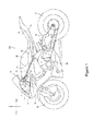
- Figure 1 is a left side view of the motorcycle 100 according to the embodiment.
- the front, back, left, and right refer to these positions as viewed from a rider seated on a seat 19 of the motorcycle 100.
- the arrow F indicates a forward direction of the motorcycle 100
- the arrow B indicates a backward direction of the motorcycle 100.
- the arrow R indicates a rightward direction of the motorcycle 100
- the arrow L indicates a leftward direction of the motorcycle 100.
- the arrow U indicates an upward direction of the motorcycle 100.
- the motorcycle 100 includes a vehicle body frame 10, a power unit 18, a front wheel 26, a rear wheel 27, and an aluminum fuel tank 30.
- the aluminum fuel tank 30 will be simply referred to as the "fuel tank 30" in some cases.
- the 'aluminum fuel tank' includes aluminum based fuel tanks, which may be formed from aluminum, or aluminum alloy, for example.
- the vehicle body frame 10 includes a head pipe 11, tank frames 12, rear frames 13, and rear arms 14.
- the head pipe 11 is provided at a front part of the motorcycle 100.
- the tank frames 12 are formed as a pair of left and right tank frames.
- the tank frames 12 extend rearward from the head pipe 11.
- the left and right tank frames 12 each have a part curved downward.
- the curved parts of the tank frames 12 are connected with left and right rear frames 13, respectively.
- the rear arms 14 are connected to rear ends of the tank frames 12.
- the head pipe 11 has a steering shaft 17 rotatably inserted therein.
- a handle 16 is connected to an upper part of the steering shaft 17.
- a front fork 15 is attached to the steering shaft 17 through a bracket (not shown).
- the front wheel 26 is supported rotatably at a lower end of the front fork 15. The front wheel 26 rotates to the left and right as the handle 16 is operated.
- the rear wheel 27 is supported rotatably at rear ends of the rear arms 14.
- the rear wheel 27 rotates as motive power from the power unit 18 is transmitted thereto.
- the fuel tank 30 is attached to the tank frames 12 and the rear frames 13.
- the seat 19 is disposed behind the fuel tank 30.
- a front part of the seat 19 covers a part of a rear part of the fuel tank 30.
- a front cowl 21 is provided ahead or forwardly of the handle 16.
- a cover 22 is provided behind the handle 16.
- a rear part of the cover 22 covers a part of a front part of the fuel tank 30.
- a pair of left and right side covers 23 is provided under the cover 22.
- the side covers 23 are attached to the tank frames 12 and the rear frames 13.
- the side covers 23 cover a part of a lower part of the fuel tank 30 in a side view of the motorcycle 100.
- the seat 19, the cover 22, and the side covers 23 cover the rear part, the front part, and the lower parts of the side surfaces of the fuel tank 30 to surround them. Therefore, the part of the fuel tank 30 covered by the seat 19, the cover 22, and the side covers 23 is not visible in the outer appearance of the motorcycle 100 in a side view and a plan view.
- FIG 2 is a perspective view of first and second panels 41 and 61 that form the fuel tank 30.
- Figure 3 is a plan view of the fuel tank 30.
- Figure 4 is a left side view of the fuel tank 30.
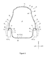
- Figure 5 is a rear sectional view taken along line A-A in Figure 4 .
- top-bottom, front-back, and left-right directions of the fuel tank 30 refer to these directions when the fuel tank 30 is provided in the motorcycle 100.
- the first panel 41 forms an upper part of the fuel tank 30.
- the second panel 61 forms a lower part of the fuel tank 30.
- the first panel 41 will be described first.
- the first panel 41 includes a first panel main body 42 and a first flange 43.
- the first panel main body 42 includes an upper surface 51 and a pair of side surfaces 52.
- the upper surface 51 forms an upper part of the first panel main body 42 from the front part to the rear part.
- the pair of side surfaces 52 forms a side part of the first panel main body 42 from the front part to the rear part.
- the side surfaces 52 are formed continuously with the upper surface 51.
- the side surfaces 52 are opposed in the left-right direction.
- the first flange 43 is formed continuously with an end of the first panel main body 42.
- the first flange 43 is formed to surround the first panel main body 42.
- the width of the first flange 43 or the distance from an arbitrary edge of the first flange 43 to an edge of the first panel main body 42 is for example from 3 mm to 10 mm.
- the first flange 43 has a width of 5 mm.
- at least part or all of a junction between the first flange 43 and the first panel main body 42 may be associated with a change in slope or surface shape or function.
- the first flange 43 is formed to combine the first panel 41 with the second panel 61.
- the first panel main body 42 has a stepped part 57.
- the stepped part 57 is formed entirely around the first panel main body 42.
- the position of the surface of the first panel main body 42 changes stepwise by one step.
- the amount of change in the position of the surface at the stepped part 57 is for example in a range from 2 mm to 5 mm.
- the position of the surface of the part ahead of the stepped part 57 is 3 mm to 4 mm lower stepwise in the downward direction than the level of the surface of the part behind the stepped part 57 in the vicinity of the stepped part 57.
- the stepped part 57 is formed to reduce the step between the first panel 41 and the seat 19, the cover 22, and the side covers 23 when the fuel tank 30 is provided in the motorcycle 100, and the seat 19, the cover 22, and the side covers 23 are placed on the rear part, front part, and lower parts of the side surfaces of the fuel tank 30, respectively.
- the stepped part 57 defines a boundary between the part of the first panel 41 covered with the seat 19, the cover 22, and the side covers 23 and the part not covered with these components and visible in the outer appearance of the motorcycle 100 while the fuel tank 30 is provided in the motorcycle 100.
- the part of the first panel main body 42 nearer to the edge than the stepped part 57 and the first flange 43 are covered with the seat 19, the cover 22, and the side covers 23 while the fuel tank 30 is provided in the motorcycle 100.
- the part of the first panel main body 42 surrounded by the stepped part 57 corresponds to the part that is not covered with the seat 19, the cover 22, and the side covers 23 and visible in the outer appearance of the motorcycle 100 while the fuel tank 30 is provided in the motorcycle 100.
- the upper surface 51 of the first panel 41 has an opening 46.
- a fuel feed portion (not shown) is attached to the opening 46.
- the fuel feed portion may include a fuel inlet and a cap that closes/opens the fuel inlet.
- the second panel 61 includes a second panel main body 62 and a second flange 63.
- the second panel main body 62 includes a base part 71 and a front wall 72.
- the base part 71 has a bottom part 73, a front part 74, a rear part 75, and a pair of side parts 76.
- the front wall 72 is formed continuously with the front part 74 of the base part 71.
- the second flange 63 is formed continuously with the edge of the second panel main body 62.
- the second flange 63 is formed to entirely surround the second panel main body 62.
- the width of the second flange 63 in other words, the distance from an arbitrary edge of the second flange 63 to an edge of the second panel main body 62 is for example from 3 mm to 10 mm.
- at least part or all of a junction between the second flange 63 and the second panel main body 52 may be associated with a change in slope or surface shape.
- the second flange 63 has a width of 5 mm.
- the second flange 63 is formed to combine the second panel 61 with the first panel 41.
- the second panel 61 includes attachment portions 79, 81, and 82.
- the attachment portions 79, 81, and 82 are used to secure the fuel tank 30 to the rear frames 13 and the tank frames 12.
- the second flange 63 is not formed in the area where the attachment portions 81 and 82 are formed.
- An opening 66 is formed at the bottom part 73 of the second panel 61.
- a support (not shown) is attached to the opening 66.
- the support supports a fuel pump (not shown) disposed in the fuel tank 30.
- the first and second panels 41 and 61 are produced by press-molding sheet metal of an aluminum-based material.
- the press-molded, first and second panels 41 and 61 are combined with each other and put together by welding the first and second flanges 43 and 63 together around the entire periphery.
- the second flange 63 is not formed in the area where the attachment portions 81 and 82 are formed, and therefore the first flange 43 is welded to the attachment portions 81 and 82 in that area.
- the fuel tank 30 will be described.
- the pair of left and right tank frames 12 and the pair of left and right rear frames 13 are indicated by virtual lines.
- the virtual lines show the positional relation between the fuel tank 30 and the tank frames 12 and the rear frames 13 while the fuel tank 30 is attached to the tank frames 12 and the rear frames 13.
- the first panel 41 that forms the fuel tank 30 has a greater width in the left and right direction at the front part than at the rear part in a plan view.
- the distance between the side surfaces 52 of the first panel 41 in the left-right direction gradually decreases from the front part to the rear part of the first panel 41 in a plan view.
- the fuel tank 30 is attached to extend between the pair of left and right tank frames 12 and the pair of left and right rear frames 13.
- the first and second panels 41 and 61 are connected by a joint 32 and a weld part 33.
- the joint 32 is formed by welding the first and second flanges 43 and 63 together entirely around the first and second panels 41 and 61.
- the weld part 33 is formed by welding the first flange 43 to the attachment portions 81 and 82.
- the stepped part 57 is visible at the front and rear parts of the first panel main body 42.
- the part of the front part ahead of the stepped part 57 is covered with the cover 22 while the tank 30 is provided in the motorcycle 100.
- the part of the rear part behind the stepped part 57 is covered with the seat 19.
- the part of the first panel main body 42 behind the stepped part 57 provided at the front part and the part of the first panel main body 42 ahead of the stepped part 57 provided at the rear part are not covered with the cover 22 and the seat 19 and therefore visible in the outer appearance of the motorcycle 100.
- the upper surface 51 of the first panel 41 curves upward. More specifically, a middle part 511 positioned between a front end and a rear end of the first panel 41 is the highest. The height of the upper surface 51 gradually increases in the up-down direction from the front end to the middle part 511 and gradually decreases from the middle part 511 to the rear end.
- the middle part 431 in the front-back direction curves to project downward in a side view. More specifically, the first flange 43 is inclined obliquely downward from the front part to the middle part 431 and obliquely upward from the middle part 431 to the rear part.
- the fuel tank 30 is attached so that the first flange 43 does not interfere with the tank frames 12 and the rear frames 13.
- the stepped part 57 extends downward from the upper part at the front part of the side surface 52 and upward from the lower part at the rear part.
- the stepped part curves upward at the middle part of the side surface 52.
- the cover 22 is placed on the part ahead of and above a connection portion 57A between the stepped part 57 that extends downward from the upper part at the front part of the side surface 52 and the stepped part 57 that is curved upward at the middle part of the side surface 52.
- the seat 19 is placed on the part behind and above a connection portion 57B between the stepped part 57 that extends upward from the lower part at the rear part of the side surface 52 and the stepped part 57 that curves upward at the middle part of the side surface 52.
- the side cover 23 is placed on the part positioned below the stepped part 57 that curves upward at the middle part of the side surface 52.
- the first and second panels 41 and 61 form a space 31 that stores fuel inside the fuel tank 30.
- the first panel 41 defines an upper part of the space 31 that stores fuel.
- the second panel 61 defines a lower part of the space 31 that stores fuel.
- An inner surface 44 of the first panel 41 and an inner surface 64 of the second panel 61 face the space 31 that stores fuel.
- An outer surface 45 of the first panel 41 and an outer surface 65 of the second panel 61 face the outside of the fuel tank 30.
- the base part 71 of the second panel 61 is provided in a space between the left and right tank frames 12 and the left and right rear frames 13.
- a connection portion 77 is formed at each of upper parts of the pair of side parts 76 of the second panel 61.
- the connection portion 77 is formed to curve toward the outside of the fuel tank 30 and downward with respect to the side part 76 of the base part 71.
- the connection portion 77 corresponds to the side surface 52 of the first panel 41. More specifically, the connection portion 77 corresponds to the lower part of the side surface 52 in shape and size in the left-right direction.
- the side cover 23 is provided on the left of the left joint 32 and the side cover 23 is provided on the right of the right joint 32.
- the part of the lower part of the side surfaces 52 of the first panel 41 having the largest distance in the left-right direction corresponds to the positions of the outer surfaces of the tank frames 12 and the rear frame 13 in the left-right direction. More specifically, there is only a narrow step in the left-right direction between the part of the lower part of the side surface 52 of the first panel 41 having the largest distance in the left-right direction and the outer surfaces of the tank frames 12 and the rear frames 13 in the left-right direction. Therefore, when the side covers 23 are attached to the tank frames 12 and the rear frames 13, the step between the side surface 52 of the first panel 41 and the side cover 23 can be reduced.
- FIG. 6 is a plan view of the first panel 41.
- Figure 7 is a left side view of the first panel 41.
- Figure 8 is a rear sectional view taken along line B-B in Figure 7 .
- first region A1 the region in which the distance between the pair of side surfaces 52 in the left-right direction gradually decreases from the front part to the rear part of the first panel 41.
- second region A2 the region in which the height of the upper surface 51 in the up-down direction gradually decreases from the front part to the rear part of the first panel 41.
- a ridge 55 is formed at the side surface 52 of the first panel main body 42.
- the ridge 55 is positioned at a boundary between the upper surface 51 and the side surface 52 of the first panel main body 42.
- the outer surface 45 of the first panel 41 is raised.
- the ridge 55 extends in the front-back direction of the first panel main body 42. A rear part of the ridge 55 is inclined downward.
- the side surface 52 of the first panel main body 42 has a recess 58.
- the recess 58 is a curved surface formed by a recessed portion of the outer surface 45 of the first panel 41.
- the recess 58 is formed in a region surrounded by the ridge 55 and the stepped part 57.
- the recess 58 extends backward from the middle part of the first panel main body 42 in a side view.
- the recess 58 extending backward in the side view means that the recess 58 has a width in the up-down direction and is formed backward from the middle part of the side surface 52.
- the first flange 43 is formed continuously with an edge of the first panel main body 42.
- the first flange 43 has a first front flange 43A, a first rear flange 43B, and a first side flange 43C.
- the first front flange 43A, the first rear flange 43B, and the first side flange 43C are continuous and formed to surround the first panel main body 42.
- the first flange 43 has such a shape that the second flange 63 has an excess part 78 when the first and second panels 41 and 61 are combined with each other (see Figures 16 and 17 ).
- the excess part 78 is the edge of the second flange 63 that projects beyond the edge of the first flange 43.
- the first front flange 43A is formed continuously with a front end of the upper surface 51.
- the first front flange 43A extends forward from the front end of the upper surface 51 in a side view.
- a lower end of the first front flange 43A is continuous with the first side flange 43C.
- the first rear flange 43B is formed continuously with a rear end of the upper surface 51.
- the first rear flange 43B extends backward from the rear end of the upper surface 51 in a side view.
- a lower end of the first rear flange 43B is continuous with the first side flange 43C.
- the first side flange 43C is formed continuously with a lower end of the side surface 52.
- the first side flange 43C has a part inclined obliquely downward from the front part to the middle part 431 and a part inclined obliquely upward from the middle part 431 to the rear part in a side view. More specifically, in the first side flange 43C, the middle part 431 is curved to project downward.
- the first front flange 43A is formed continuously with the front end of the upper surface 51.
- the first front flange 43A extends in the left-right direction along the front end of the upper surface 51 in a plan view.
- the right and left ends of the first front flange 43A are continuous with the first side flange 43C.
- the first rear flange 43B is formed continuously with the rear end of the upper surface 51.
- the first rear flange 43B extends in the left-right direction along the rear end of the upper surface 51 in a plan view.
- the right and left ends of the first rear flange 43B are continuous with the first side flange 43C.
- the side surface 52 has a convex surface 54A, a convex surface 54B, and a concave surface 53A.
- the convex surface refers to a curved surface formed by a raised part of the outer surface 45 of the first panel 41 in a rear sectional view.
- the concave surface refers to a curved surface formed by a recessed portion of the outer surface 45 of the first panel 41 in a rear sectional view.
- the concave surface 53A is formed between the convex surfaces 54A and 54B in a rear sectional view.
- the concave surface 53A connects the convex surfaces 54A and 54B.
- the first panel main body 42 has a concave surface 53C.
- the concave surface 53C is formed above the convex surface 54A in a rear sectional view.
- the concave surface 53C forms a part of the upper surface 51 of the first panel main body 42.
- the ridge 55 connects the concave surface 53C and the convex surface 54A.
- the ridge 55 is positioned at a boundary between the upper surface 51 and the side surface 52 of the first panel main body 42 in a rear sectional view.
- a recess 58 is formed by a part of the convex surface 54A, a part of the convex surface 54B, and the concave surface 53A. More specifically, the concave surface 53A is formed in a recessed position with respect to a virtual line 58A connecting the apex of the convex surface 54A and the apex of the convex surface 54B in a rear sectional view.
- the first side flange 43C is formed continuously with the lower end of the side surface 52.
- the first side flange 43C formed on the left of the first panel 41 extends obliquely leftward and downward.
- the opening angle D1 formed between the virtual line V1 and the left first side flange 43C is set from 3° to 60°.
- the opening angle D1 is preferably set from 20° to 40°.
- the first side flange 43C formed on the right of the first panel 41 extends obliquely rightward and downward.
- the opening angle D2 formed between the virtual line V2 and the right first side flange 43C is set from 3° to 60°.
- the opening angle D2 is preferably set from 20° to 40°.
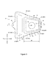
- Figure 9 is a plan view of the second panel 61.
- Figure 10 is a left side view of the second panel 61.
- Figure 11 is a side sectional view taken along line C-C in Figure 9 .
- Figure 12 is a rear sectional view taken along line D-D in Figure 10 .
- the second panel 61 includes the second panel main body 62 and the second flange 63.
- the second panel main body 62 includes the base part 71 and the front wall 72.
- the region in the front-back direction where the base part 71 is formed is a third region A3.
- connection portions 77 are provided at the pair of side parts 76 that form the base part 71.
- the left connection portion 77 has a width in the left-right direction and extends in the front-back direction.
- the right connection portion 77 has a width in the left-right direction and extends in the front-back direction.
- the second flange 63 is formed continuously with the edge of the second panel main body 62.
- the second flange 63 has a second front flange 63A, a second rear flange 63B, and a second side flange 63C.
- the second front flange 63A, the second rear flange 63B, and the second side flange 63C are formed continuously to surround the second panel main body 62.
- the second front flange 63A is formed continuously with a front end of the front wall 72.
- the second front flange 63A extends forward from the front end of the front wall 72 in a plan view.
- the second front flange 63A is not formed at the attachment portion 82.
- the left and right ends of the second front flange 63A are continuous with the second side flanges 63C.
- the second rear flange 63B is formed continuously with a rear end of the base part 71.
- the second rear flange 63B extends backward from the rear end of the base part 71 in a plan view.
- the left and right ends of the second rear flange 63B are continuous with the second side flanges 63C.
- the second side flange 63C is formed continuously with the front wall 72 and the left and right ends of the base part 71. In the third region A3, the second side flange 63C is formed continuously with the connection portion 77 of the base part 71. Note that in the third region A3, the second side flange 63C is formed downward and therefore its width appears narrow in a plan view.
- connection portion 77 is formed at the pair of side parts 76 that form the base part 71.
- the front wall 72 is formed continuously with the front part 74 of the base part 71.
- the second front flange 63A is formed continuously with the front end of the front wall 72.
- the second front flange 63A extends forward from the front end of the front wall 72 in a side view.
- the second rear flange 63B is formed continuously with the rear end of the base part 71.
- the second rear flange 63B extends backward from the rear end of the base part 71 in a side view.
- the second side flange 63C is formed continuously with the lower end of the front wall 72 and the lower end of the connection portion 77 of the base part 71.
- the second side flange 63C is curved so that its middle part 631 between the front part and the rear part projects downward.
- the second side flange 63C is not formed at the attachment portion 81.
- the left and right ends of the front wall 72 project ahead of the middle part of the front wall 72 in the left-right direction in a side sectional view. More specifically, at the inner surface 64 of the front wall 72, the middle part in the left-right direction projects behind both ends in the left-right direction.
- connection portions 77 are formed at the upper parts of the pair of side parts 76 that form the base part 71.
- connection portions 77 are curved outward from the side parts 76 of the base part 71. Being curved outward refers to the state in which the left connection portion 77 is curved to the left, so that the end of the connection portion 77 extends obliquely leftward and downward. It also refers to the state in which the right connection portion 77 is curved to the right, so that the end of the connection portion 77 extends obliquely rightward and downward.
- the second side flange 63C is formed continuously with the end of the curved connection portion 77.
- the second side flange 63C Since the second side flange 63C is formed at the end of the curved connection portion 77, the second side flange 63C has an angle with respect to the side part 76.
- the angle formed by the outer surface 65 of the side part 76 and the outer surface 65 of the second side flange 63C is a third opening angle D3.
- the third opening angle D3 is set from 3° to 60° corresponding to the opening angles D1 and D2 of the first side flange 43C formed at the first panel 41.
- the opening angle D3 is preferably set from 20° to 40°.
- the radius of curvature R of the connection portion 77 that connects the second panel main body 62 and the second flange 63 is set from 6 mm to 12 mm. More specifically, the radius of curvature R is the radius of curvature of the outer surface 65 at the part of the connection portion 77 curved outward with respect to the side part 76 of the base part 71.
- the manufacturing method includes a first panel forming step (a first step), a second panel forming step (a second step), a combining step (a third step), and a welding step (a fourth step).
- the first panel 41 described above is formed.
- the first panel 41 is formed by press-working a sheet of an aluminum-based material. More specifically, the first panel main body 42 and the first flange 43 are formed by press-working. Specific shapes of the first panel main body 42 and the first flange 43 are as described above.
- the first flange 43 is formed so that the edge of the second flange 63 has the excess part 78 that projects beyond the edge of the first flange 43 while the first and second panels 41 and 61 are combined with each other ( Figures 16 and 17 ).
- the first panel 41 according to the embodiment is formed by press-working a single sheet of an aluminum-based material.
- a sheet of Al (pure aluminum)or aluminum alloy such as an Al-Mg-based alloy, or an Al-Si-Mg-based alloy is preferably used for forming the first panel 41 in consideration of strength and workability.
- the first panel 41 preferably has a reduced sheet thickness in order to reduce the weight of the fuel tank 30.
- the thickness of the first panel 41 is determined in consideration of workability and strength required for the fuel tank 30.
- the above-described second panel 61 is formed.
- the second panel 61 is formed by press-working a sheet of an aluminum-based material. More specifically, the second panel main body 62 and the second flange 63 are formed by press-working. Specific shapes of the second panel main body 62 and the second flange 63 are as described above.
- the second flange 63 is formed to have the excess part 78 ( Figures 16 and 17 ) when the first and second panels 41 and 61 are combined with each other.
- Sheet metal of Al pure aluminum
- an aluminum alloy such as an Al-Mg-based alloy, or an Al-Si-Mg-based alloy is preferably used for forming the second panel 61 in consideration of strength and workability similarly to the first panel 41.
- the second panel 61 preferably has a reduced sheet thickness in order to reduce the weight of the fuel tank 30.
- the sheet thickness of the second panel 61 is determined in consideration of workability and strength required for the fuel tank 30.
- the opening angle D3 of the second flange 63 with respect to the second panel main body 62 is set in a range from 20° to 40°. More specifically, the angle of the curved part of the connection portion 77 is set so that the opening angle D3 of the second flange 63 with respect to the second panel main body 62 is set in a range from 20° to 40°.
- the radius of curvature R of the connection portion 77 that connects the second panel main body 62 and the second flange 63 is set in a range from 6 mm to 12 mm.
- the second panel 61 may be formed by press-working a single sheet of metal or by putting together a number of press-worked members.
- the base part 71 and the front wall 72 that form the second panel 61 may be formed separately by press-working.
- the base part 71 and the front wall 72 obtained by separate press-working are joined by welding means to form the second panel 61.
- the base part 71 and the front wall 72 may be welded by arc welding means such as MIG welding or laser welding means.
- the second panel 61 may be separated into three or more parts and formed, and the parts may be put together to form the second panel 61.
- Figure 13 is a left side view showing how the second panel 61 is provided on the first panel 41 in the combining step.
- Figure 14 is a rear sectional view taken along line E-E in Figure 13 .
- Figure 15 is a left side view showing how the second panel 61 is provided on the first panel 41 in the combining step.
- Figure 16 is an enlarged rear sectional view taken along line F-F in Figure 15 .
- Figure 17 is an enlarged rear sectional view taken along line G-G in Figure 15 .
- the first and second flanges 43 and 63 are opposed and the first and second panels 41 and 61 are combined with each other.
- the first flange 43 of the first panel 41 and the second flange 63 of the second panel 61 are opposed. More specifically, the first surface 47 of the first flange 43 is continuous with the inner surface 44 of the first panel main body 42 is opposed to the second surface 67 of the second flange 63 continuous with the inner surface 64 of the second panel main body 62.
- the second panel 61 is placed on the first panel 41 and the first and second panels 41 and 61 are combined with each other. While the first and second panels 41 and 61 are combined with each other, the first and second panels 41 and 61 are arranged so that the excess part 78 of the edge of the second flange 63 projects beyond the edge of the first flange 43 at the entire periphery. Note that the excess part 78 is not formed at the attachment portions 81 and 82 where the second flange 63 is not formed.
- the first side flange 43C and the second side flange 63C are combined with each other.
- the excess part 78 corresponds to the edge of the second side flange 63C that projects beyond the edge of the first side flange 43C.
- the first side flange 43C is combined with the second side flange 63C in the region other than the third region.
- the excess part 78 corresponds to the part of the edge of the second side flange 63C that projects beyond the edge of the first side flange 43C.
- the first front flange 43A is combined with the second front flange 63A.
- the excess part 78 corresponds to the part of the edge of the second front flange 63A that projects beyond the edge of the first front flange 43A.
- the first rear flange 43B is combined with the second rear flange 63B.
- the excess part 78 corresponds to the part of the edge of the second rear flange 63B that projects beyond the edge of the first rear flange 43B.
- Figure 18 is an enlarged rear sectional view showing a positional relation between a part taken along line F-F in Figure 15 and a torch T in the welding step.
- Figure 19 is an enlarged rear sectional view showing a positional relation between a part taken along line G-G in Figure 15 and the torch T in the welding step.
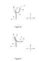
- Figure 20 is an enlarged rear sectional view showing the part taken along line F-F in Figure 15 after welding in the welding step.
- Figure 21 is an enlarged rear sectional view showing the part taken along line G-G in Figure 15 after welding in the welding step.
- the edges of the first and second flanges 43 and 63 are welded together.
- the torch T is provided on the side of the first flange 43 with respect to a virtual plane P defined by extending the second flange 63.
- the torch T is provided on the side of the first flange 43 with respect to the virtual plane P, so that the edge of the first flange 43 and the edge of the second flange 63 can be welded together appropriately even when the excess part 78 is formed.
- the second panel 61 is thinner than the first panel 41.
- the thinner second flange 63 melts more easily than the first flange 43. Therefore, when the edges of the first and second flanges 43 and 63 are welded together, the excess part 78 of the second flange 63 melts faster than the edge of the first flange 43, and a weld bead 90 forms at the edges of the first and second flanges 43 and 63.
- the excess part 78 no longer exists where the weld bead 90 forms.
- the weld bead 90 forms the joint 32.
- the second panel 61 is provided on the first panel 41 and therefore when the first and second flanges 43 and 63 are welded together, the weld bead 90 is likely to form at the top edges of the first and second flanges 43 and 63 by gravity.
- first and second flanges 43 and 63 may be secured provisionally.
- the first and second flanges 43 and 63 may be secured provisionally by forming members for provisional securing in advance at the first and second flanges 43 and 63 and the members may be welded together to provisionally secure the first and second flanges 43 and 63.
- the members for provisional securing are removed.
- the first and second flanges 43 and 63 may be provisionally secured directly to each other.
- the method of manufacturing the fuel tank 30 may include the first panel forming step (first step), the second forming step (second step), the combining step (third step), and the welding step (fourth step).
- first panel forming step a sheet of an aluminum-based material is formed into the first panel 41.
- the first panel forming step includes forming the first flange 43 to be combined with the first panel main body 42 and the second panel 61.
- second panel forming step a sheet of an aluminum-based material is formed into the second panel 61 that is thinner than the first panel 41.
- the second panel forming step includes forming the second flange 63 to be combined with the second panel main body 62 and the first panel 41.
- the first and second flanges 43 and 63 are opposed, and the first panel 41 and the second panel 61 are combined with each other so that the excess part 78 of the edge of the second flange 63 projects beyond the edge of the first flange 43.
- the edge of the first flange 43 and the edge of the second flange 63 are welded together.
- correction to reduce a gap generated between the first and second flanges 43 and 63 can be carried out if any by pinching and deforming the first and second flanges 43 and 63. More specifically, the first and second flanges 43 and 63 are pinched from the outside using a jig or the like to deform, so that a gap generated between the first and second flanges 43 and 63 can be reduced. Therefore, an allowance may be provided in dimensional management of the first and second flanges 43 and 63 in the gap direction while the welding accuracy can be improved.
- the second flange 63 has the excess part 78 that projects beyond the edge of the first flange 43.
- the second flange 63 is formed to have the excess part 78 with respect to the first flange 43. Therefore, even if there is a dimensional error in the first and second flanges 43 and 63, the positional relation in which the edge of the second flange 63 projects beyond the edge of the first flange 43 is easily maintained while the first and second panels 41 and 61 are combined. More specifically, if there is a dimensional error in the first and second flanges 43 and 63, a reversed positional relation in which the edge of the first flange 43 projects beyond the edge of the second flange 63 is unlikely.
- the first and second flanges 43 and 63 may be welded together while allowing dimensional errors in the first and second flanges 43 and 63, so that an allowance is provided in dimensional management of the edges of the first and second flanges 43 and 63 in the projecting direction while the welding accuracy can be improved.
- the second panel 61 is thinner than the first panel 41 and the thinner second flange 63 more easily melts than the first flange 43 when the edges of the first and second flanges 43 and 63 are welded together. Therefore, the excess part 78 of the second flange 63 melts faster than the first flange 43 when the edges of the first and second flanges 43 and 63 are welded together. As a result, the weld bead 90 formed from the excess part 78 forms at the edges of the first and second flanges 43 and 63, and the first flange 43 and the second flanges 63 are put together.
- the first surface 47 of the first flange 43 continuous with the inner surface 44 of the first panel main body 42 is opposed to the second surface 67 of the second flange 63 continuous with the inner surface 64 of the second panel main body 62.
- the opening angle D3 of the second flange 63 with respect to the second panel main body 62 is set in a range from 20° to 40°.
- the opening angle D3 of the second flange 63 with respect to the second panel main body 62 is set in a range from 20° to 40°. Therefore, the fuel tank 30 may have a sufficient capacity while a space for operation to correct the gap between the first and second panels 41 and 61 and correct welding may be provided.
- opening angles D1 and D2 of the first flange 43 and the opening degree D3 of the second flange 63 may be set to the same angle, so that a gap is unlikely to form between the first and second flanges 43 and 63 when the first and second flanges 43 and 63 are combined.
- the opening angles D1 and D2 of the first flange 43 may be smaller than the opening angle D3 of the second flange 63, so that a gap is unlikely to form between the first flange 43 and the second flange 63 when the first and second flanges 43 and 63 are combined.
- connection portion 77 as the connecting part between the second panel main body 62 and the second flange 63 has a radius of curvature from 6 mm to 12 mm.
- the first and second flanges 43 and 63 are extended in the horizontal direction, it would increase the operability or correction would be easier in welding. If the width of the fuel tank cannot be increased, the fuel tank cannot have a sufficient capacity. Conversely, if the first and second flanges 43 and 63 are extended downward, it would lower the operability and correction would not be easier in welding but the fuel tank can have a sufficient capacity.
- the radius of curvature of the connecting part between the second panel main body 62 and the second flange 63 is set from 6 mm to 12 mm. Therefore, the fuel tank 30 may have a sufficient capacity while a space for operation to correct a gap between the first and second panels 41 and 61 and correct welding may be provided.
- the second panel 61 is provided on the first panel 41.
- the second panel 61 is provided on the first panel 41 and the panels are welded together in this state.
- the weld bead 90 easily forms at the edges of the first and second flanges 43 and 63 by gravity during welding, so that the fuel tank 30 may easily improve its airtightness.
- the torch T is provided on the side of the first flange 43 with respect to the virtual plane P defined by extending the second flange 63.
- the arrangement of the torch T makes it easier to aim the edges of the first and second flanges 43 and 63 with the torch T.
- MIG welding means or laser welding means is used.
- the MIG welding or laser welding means is suitable for welding aluminum, and therefore the welding can be carried out with high accuracy.
- the second panel 61 is thinner than the first panel 41. Since the welding accuracy can be improved, the fuel tank 30 with improved airtightness can be provided.
- the fuel tank 30 according to the embodiment has the weld bead 90 at the joint 32 between the edges of the first and second flanges 43 and 63, and therefore the fuel tank 30 with improved airtightness can be provided.
- a straddled vehicle 100 including the fuel tank 30 having reduced weight according to the embodiment can therefore have high traveling performance.
- the method of manufacturing an aluminum fuel tank, the aluminum fuel tank, and the straddled vehicle according to the invention are not limited to those according to the embodiment described above.
- the first panel 41 forms the upper part of the fuel tank 30, and the second panel 61 forms the lower part of the fuel tank 30.
- the first and second panels 41 and 61 need only be members that form the fuel tank 30. More specifically, it is only necessary that the first and second panels 41 and 61 having different thicknesses are welded together and form at least a part of the fuel tank 30.
- the first panel 41 may form the lower part of the fuel tank 30 and the second panel 61 may form the upper part of the fuel tank 30.
- the first panel 41 formed in the first panel forming step and the second panel 61 formed in the second panel forming step do not have to be formed in this order and the second panel 61 may be formed first or the panels may be formed simultaneously.
- the shape of the fuel tank 30 is not limited to the shape according to the embodiment.
- the tank may have an outer shape different from the shown shape.
- the position of the first and second flanges 43 and 63 to form the joint 32 of the first and second panels 41 and 61 may be in a different position from the above for example in consideration of the design of a straddled vehicle or the layout of components.
- the straddled vehicle is the touring motorcycle 100, but the straddled vehicle may be a motorcycle other than the touring motorcycle or a three-wheeled or four-wheeled straddled vehicle.
- straddled vehicle or motor vehicle used herein, and as used in the art, is meant to include the following terms also used in the art:
- references to aluminum-based, aluminum and aluminum alloys can also be written as aluminium-based, aluminium and aluminium alloys respectively.
Landscapes
- Engineering & Computer Science (AREA)
- Physics & Mathematics (AREA)
- Plasma & Fusion (AREA)
- Mechanical Engineering (AREA)
- Optics & Photonics (AREA)
- Cooling, Air Intake And Gas Exhaust, And Fuel Tank Arrangements In Propulsion Units (AREA)
Abstract
Description
- The present invention relates to a method of manufacturing an aluminum fuel tank, an aluminum fuel tank, and a straddled vehicle or a straddle-type or saddle-ride vehicle. The invention more particularly relates to a method of manufacturing a fuel tank formed using a sheet metal of an aluminum-based material, a fuel tank formed using sheet metal of an aluminum-based material, and a straddled vehicle having an aluminum fuel tank.
- A fuel tank is for example provided in a straddled vehicle. An example of the straddled vehicle is a motorcycle.
- Iron has been known as a typical material for a fuel tank. In order to produce a lightweight fuel tank, an aluminum-based material (e.g. aluminum or an aluminum alloy) is used as a material for a fuel tank in some cases. In the following description, the aluminum-based material will be simply referred to as aluminum.
- A fuel tank disclosed by
JP 2006-168713 A JP 2006-168713 A - In the conventional fuel tank described above, however, it is difficult to weld the upper member and the lower member together. One reason for the difficulty is that welding aluminum itself is difficult, and another reason is that the dimensions of the upper and lower members must be managed strictly in order to keep sufficient welding accuracy between the upper and lower members.
- When the upper member and the lower member are placed on each other in order to weld these members together, a gap may be generated at parts to be welded because of a dimensional error. If the gap is large, it would be hard to achieve high accuracy in welding the upper member and the lower member together.
- If a gap is generated at parts to be welded, welding may be carried out while the gap is corrected. For example, the upper member may be pressed against the lower member to narrow the gap during welding. However, it would not be easy to correct the gap because the pressure may deform the lower member.
- Alternatively, the parts to be welded may be pinched to reduce the gap during welding. However, the parts to be welded must be pinched both from the inner and outer sides using a jig while the upper and lower members are placed on each other. While the upper and lower members are placed on each other, it would be difficult to insert the jig inside. Therefore, it would not be easy to weld while the parts to be welded are pinched to reduce the gap.
- As described above, in the conventional fuel tank, it is be difficult to correct a gap generated between the parts of the upper and lower members to be welded and high welding accuracy cannot be achieved. Therefore, strict dimensional management must be carried out to reduce the gap between the upper member and the lower member.
- When the members having different thicknesses are welded together, the thinner member may melt faster than the thicker member. If the thinner member melts to excess, a weld bead may not form in an intended position. For example, as disclosed by
JP 2006-168713 A Figure 17 , a dimensional error in a position for welding an end of the upper member and an outer surface of the lower member may cause an error in an overlapping position between the upper member and the lower member. When welding is carried out in this state, the end of the thinner upper member cannot be welded correctly, the upper member may melt to excess, and a weld bead may not form in an intended position. Therefore, strict dimensional management must be performed so that the error in the overlapping position between the upper and lower members is reduced. - An object of at least one embodiment of at least one aspect of the invention is to provide a method of manufacturing an aluminum based fuel tank that can provide an allowance in dimensional management of members that form the fuel tank while improving welding accuracy, an aluminum fuel tank manufactured by such a method, and a straddled vehicle having such an aluminum fuel tank.
- It is an object of at least one embodiment of at least one aspect of the present invention to obviate or at least mitigate one or more problems or disadvantages in the prior art.
- Various aspects of the present invention are defined in the independent claims. Some preferred features are defined in the dependent claims.
- According to a first aspect of the present invention is a method of manufacturing a fuel tank, such as an aluminum-based or aluminium-based fuel tank. The fuel tank may be a fuel tank for a straddled vehicle, such as a saddle-pride vehicle or a straddle-type vehicle. The method of manufacturing may include first to fourth steps. Optionally as a first step, a first panel that forms a space for storing fuel may be provided or formed, e.g. using a sheet of an aluminum-based material. Optionally as a second step, a second panel that forms the space, and which may have a smaller thickness or sheet thickness than the first panel,may be provided or formed, e.g. using a sheet of an aluminum-based material. The first step may include a first sub step. Optionally as the first sub step of the first step and/or in the forming of the first panel, a first panel main body for storing fuel and/or a first flange to be combined with the second panel may be formed. The second step may include a first sub step. Optionally as the first sub step of the second step and/or in the forming of the second panel, a second panel main body for storing fuel and a second flange to be combined with the first panel may be formed. Optionally as the third step, the first and second panels may be combined with each other, e.g. so that the first and second flanges are opposed and an edge of the second flange may have an excess part that projects beyond an edge of the first flange. Optionally as the fourth step, the edge of the first flange and the edge of the second flange may be welded together.
- By the method of manufacturing a fuel-tank, such as an aluminum fuel tank, as described above, the first and second flanges may be opposed and the edge of the first flange and the edge of the second flange may be welded together to produce a fuel tank. If a gap is generated between the first and second flanges as the flanges are opposed, correction to reduce the gap between the first and second flanges may be carried out. More specifically, the opposed first and second flanges may be pinched from the outside using a jig or the like, so that the gap between the first and second flanges may be reduced. Therefore, an allowance may be provided in dimensional management of the first and second flanges in the direction of the gap while the welding accuracy may be improved.
- The second flange may have the excess part that projects beyond the edge of the first flange. The second flange may be formed to have the excess part with respect to the first flange. The positional relation in which the edge of the second flange may project beyond the edge of the first flange while the first and second panels are combined, may likely be maintained if there is a dimensional error in the first and second flanges. More specifically, if there is a dimensional error in the first and second flanges, a reversed positional relation in which the edge of the first flange projects beyond the edge of the second flange may be unlikely. Therefore, a dimensional error may be allowed in the first and second flanges in welding, and an allowance may be provided in dimensional management of the edges of the first and second flanges in the projecting direction while the welding accuracy may be improved.
- Moreover, the second panel may be thinner than the first panel, and the thinner second flange may more easily melt than the first flange when the edges of the first and second flanges are welded together. Therefore, when the edges of the first and second flanges are welded together, the excess part of the second flange may melt faster than the first flange. As a result, a weld bead with little or no excess part may form at the edges of the first and second flanges, and the first and second flanges may be put together.
- In the third step and/or in the combining of the first and second panels, a first surface of the first flange, which may be continuous with an inner surface of the first panel main body, and a second surface of the second flange, which may be continuous with an inner surface of the second panel main body, may be opposed.
- In the first sub step of the second step and/or in the forming of the second panel main body and the second flange, an opening angle of the second flange with respect to the second panel main body may be in a range from 3° to 60°, e.g. from 20° to 40°.
- In the first sub-step of the first step and/or in the forming the first panel main body and the first flange, an opening angle formed between a vertical virtual line in a rear sectional view through a part where the first flange and the first panel main body part are connected and the left first side flange may be in a range from 3° to 60°, e.g. from 20° to 40°.
- The opening angle of the second flange with respect to the second panel main body may correspond or be equal to the opening angle formed between a vertical virtual line in a rear sectional view through a part where the first flange and the first panel main body part are connected.
- In the first sub step of the second step and/or in the forming of the second panel main body and the second flange, a connection part between the second panel main body and the second flange may have a radius of curvature in a range from 6 mm to 12 mm.
- In the third step and/or in the combining of the first and second panels, the second panel may be provided on the first panel.
- In the fourth step and/or as part of the welding, when the excess part is welded, a welding torch may be provided on a side of the first flange with respect to a virtual plane defined by extending the second flange.
- In the fourth step and/or as part of the welding, arc welding or laser welding may be used.
- According to a second aspect of the present invention is a fuel tank, such as an aluminum-based or aluminium-based fuel tank, e.g. an aluminum or aluminum alloy fuel tank, which may be manufactured by the method of manufacturing according to the first aspect.
- The fuel tank may comprise a weld bead, which may be located at the edges of the first and second flanges.
- The fuel tank may comprise a first panel, which may be formed from an aluminum-based material. The fuel tank may comprise a second panel, which may be formed from an aluminum-based material. The second panel may have a smaller or lower thickness, e.g. sheet thickness, than the first panel. The first panel may be or comprise an upper or upmost panel. The second panel may be or comprise a lower or lowermost panel. The first and/or second panels may at least partially define a space for storing fuel. The first and/or second panels may be formed from respective sheets of an aluminum-based material, e.g. aluminum and/or an aluminum alloy.
- The first panel may comprise a first panel main body and/or a first flange. The first panel main body may comprise an upper surface and/or at least a pair of side surfaces. The upper surface may form an upper part of the first panel main body, and may extend from a front part to the rear part thereof. The pair of side surfaces may form a side part of the first panel main body, and may extend from the front part to the rear part thereof. The side surfaces may be formed continuously with the upper surface. The side surfaces may be opposed in the left-right direction. The first flange may be formed continuously with an end of the first panel main body. The first flange may be formed to surround the first panel main body.
- The second panel may comprise a second panel main body and/or a second flange. The second panel main body may comprise a base part and/or a front wall. The base part may have a bottom part, a front part, a rear part, and/or at least a pair of side parts. The front wall may be formed continuously with the front part of the base part.
- The second flange may be formed continuously with the edge of the second panel main body. The second flange may be formed to entirely surround the second panel main body.
- The first and/or second flange may be formed to combine the first panel with the second panel.
- The first panel may have a greater width in the left-right direction at the front part than at the rear part in a plan view.
- According to a third aspect of the present invention is a straddled vehicle, e.g. a saddle-ride or straddle-type vehicle. The vehicle may comprise a fuel tank, such as an aluminum-based or aluminium-based fuel tank, according to the second aspect.
- The straddled vehicle may comprise a vehicle body frame, a power unit, a front wheel, and/or a rear wheel.
- The vehicle body frame may comprise a head pipe, tank frames, rear frames and/or rear arms. The head pipe may be provided at a front part of the straddled vehicle. The tank frames may be formed as a pair of left and right tank frames. The tank frames may extend rearward from the head pipe. In a side view of the straddled vehicle, the left and right tank frames may each have a part curved downward. The curved parts of the tank frames may be connected with left and right rear frames, respectively. The rear arms may be connected to rear ends of the tank frames.
- The fuel tank may be attached to the tank frames and/or the rear frames. In a side view of the straddled vehicle, the seat may be disposed behind the fuel tank. A front part of the seat may cover a part of a rear part of the fuel tank. A front cowl may be provided ahead or forwardly of the handle. A cover may be provided behind the handle. A rear part of the cover may cover a part of a front part of the fuel tank. A pair of left and right side covers may be provided under the cover. The side covers may be attached to the tank frames and/or the rear frames. The side covers may cover a part of a lower part of the fuel tank in a side view of the motorcycle.
- The seat, the cover, and the side covers may cover the rear part, the front part, and the lower parts of the side surfaces of the fuel tank, e.g. to surround them. Therefore, a part of the fuel tank covered by the seat, the cover, and the side covers may not visible in the outer appearance of the motorcycle in a side view and a plan view.
- It will be appreciated that features analogous to those described in relation to any of the above aspects may be individually and separably or in combination applicable to any of the other aspects.
- Apparatus features produced by, analogous to, or configured to implement, those described above in relation to a method and method features analogous to the use and fabrication of those described above in relation to an apparatus are also intended to fall within the scope of the present invention.
- An embodiment of the present invention will now be described, by way of example only, with reference to the accompanying drawings, which are:
- Figure 1
- a left side view of a motorcycle according to an embodiment of the present invention;
- Figure 2
- a perspective view of first and second panels that form an aluminum fuel tank according to the embodiment;
- Figure 3
- a plan view of the aluminum fuel tank;
- Figure 4
- a left side view of the aluminum fuel tank;
- Figure 5
- a rear sectional view taken along line A-A in
Figure 4 ; - Figure 6
- a plan view of the first panel;
- Figure 7
- a left side view of the first panel;
- Figure 8
- a rear sectional view taken along line B-B in
Figure 7 ; - Figure 9
- a plan view of the second panel;
- Figure 10
- a left side view of the second panel;
- Figure 11
- a side sectional view taken along line C-C in
Figure 9 ; - Figure 12
- a rear sectional view taken along line D-D in
Figure 10 ; - Figure 13
- a left side view showing how the second panel is placed on the first panel in a third step of a method of manufacturing the aluminum fuel tank according to the embodiment;
- Figure 14
- a rear sectional view taken along line E-E in
Figure 13 ; - Figure 15
- a left side view showing how the second panel is placed on the first panel in a combining step corresponding to the third step of the method of manufacturing the fuel tank;
- Figure 16
- an enlarged rear sectional view taken along line F-F in
Figure 15 ; - Figure 17
- an enlarged rear sectional view taken along line G-G in
Figure 15 ; - Figure 18
- an enlarged rear sectional view showing a positional relation between a part taken along line F-F in
Figure 15 and a torch T in a welding step corresponding to a fourth step of the method of manufacturing the fuel tank; - Figure 19
- an enlarged rear sectional view showing a positional relation between a part taken along line G-G in
Figure 15 and the torch T in the welding step; - Figure 20
- an enlarged rear sectional view showing a state of the part taken along line F-F in
Figure 15 after welding in the welding step; and - Figure 21
- an enlarged rear sectional view of the part taken along line G-G in
Figure 15 after welding in the welding step. - A method of manufacturing an aluminum or aluminium fuel tank, an aluminum or aluminium fuel tank, and a straddled vehicle according to an embodiment of the invention will now be described in conjunction with the accompanying drawings. In the description, the straddled vehicle refers to a two-wheeled vehicle, a three-wheeled vehicle, or a four-wheeled vehicle including a power unit. A sports type motorcycle will be described as an example of the straddled vehicle according to the embodiment. The same or corresponding portions in the drawings are designated by the same reference characters and their description will not be repeated.
-
Figure 1 is a left side view of themotorcycle 100 according to the embodiment. In the following description, the front, back, left, and right refer to these positions as viewed from a rider seated on aseat 19 of themotorcycle 100. In the drawings, the arrow F indicates a forward direction of themotorcycle 100, and the arrow B indicates a backward direction of themotorcycle 100. The arrow R indicates a rightward direction of themotorcycle 100, and the arrow L indicates a leftward direction of themotorcycle 100. The arrow U indicates an upward direction of themotorcycle 100. - The
motorcycle 100 includes avehicle body frame 10, apower unit 18, afront wheel 26, arear wheel 27, and analuminum fuel tank 30. Hereinafter, thealuminum fuel tank 30 will be simply referred to as the "fuel tank 30" in some cases. In addition, the 'aluminum fuel tank' includes aluminum based fuel tanks, which may be formed from aluminum, or aluminum alloy, for example. - The
vehicle body frame 10 includes a head pipe 11, tank frames 12, rear frames 13, andrear arms 14. The head pipe 11 is provided at a front part of themotorcycle 100. The tank frames 12 are formed as a pair of left and right tank frames. The tank frames 12 extend rearward from the head pipe 11. In a side view of themotorcycle 100, the left and right tank frames 12 each have a part curved downward. The curved parts of the tank frames 12 are connected with left and right rear frames 13, respectively. Therear arms 14 are connected to rear ends of the tank frames 12. - The head pipe 11 has a steering
shaft 17 rotatably inserted therein. Ahandle 16 is connected to an upper part of the steeringshaft 17. Afront fork 15 is attached to the steeringshaft 17 through a bracket (not shown). Thefront wheel 26 is supported rotatably at a lower end of thefront fork 15. Thefront wheel 26 rotates to the left and right as thehandle 16 is operated. - The
rear wheel 27 is supported rotatably at rear ends of therear arms 14. Therear wheel 27 rotates as motive power from thepower unit 18 is transmitted thereto. - The
fuel tank 30 is attached to the tank frames 12 and the rear frames 13. In a side view of themotorcycle 100, theseat 19 is disposed behind thefuel tank 30. A front part of theseat 19 covers a part of a rear part of thefuel tank 30. - A
front cowl 21 is provided ahead or forwardly of thehandle 16. Acover 22 is provided behind thehandle 16. A rear part of thecover 22 covers a part of a front part of thefuel tank 30. A pair of left and right side covers 23 is provided under thecover 22. The side covers 23 are attached to the tank frames 12 and the rear frames 13. The side covers 23 cover a part of a lower part of thefuel tank 30 in a side view of themotorcycle 100. - As described above, the
seat 19, thecover 22, and the side covers 23 cover the rear part, the front part, and the lower parts of the side surfaces of thefuel tank 30 to surround them. Therefore, the part of thefuel tank 30 covered by theseat 19, thecover 22, and the side covers 23 is not visible in the outer appearance of themotorcycle 100 in a side view and a plan view. - The
fuel tank 30 will now be described.Figure 2 is a perspective view of first andsecond panels fuel tank 30.Figure 3 is a plan view of thefuel tank 30.Figure 4 is a left side view of thefuel tank 30.Figure 5 is a rear sectional view taken along line A-A inFigure 4 . According to the embodiment, top-bottom, front-back, and left-right directions of thefuel tank 30 refer to these directions when thefuel tank 30 is provided in themotorcycle 100. - General structures of the first and
second panels fuel tank 30 will be described. According to the embodiment, thefirst panel 41 forms an upper part of thefuel tank 30. Thesecond panel 61 forms a lower part of thefuel tank 30. Thefirst panel 41 will be described first. As shown inFigure 2 , thefirst panel 41 includes a first panelmain body 42 and afirst flange 43. The first panelmain body 42 includes anupper surface 51 and a pair of side surfaces 52. Theupper surface 51 forms an upper part of the first panelmain body 42 from the front part to the rear part. The pair of side surfaces 52 forms a side part of the first panelmain body 42 from the front part to the rear part. The side surfaces 52 are formed continuously with theupper surface 51. The side surfaces 52 are opposed in the left-right direction. - The
first flange 43 is formed continuously with an end of the first panelmain body 42. Thefirst flange 43 is formed to surround the first panelmain body 42. The width of thefirst flange 43 or the distance from an arbitrary edge of thefirst flange 43 to an edge of the first panelmain body 42 is for example from 3 mm to 10 mm. According to the embodiment, thefirst flange 43 has a width of 5 mm. Optionally, at least part or all of a junction between thefirst flange 43 and the first panelmain body 42 may be associated with a change in slope or surface shape or function. Thefirst flange 43 is formed to combine thefirst panel 41 with thesecond panel 61. - The first panel
main body 42 has a steppedpart 57. The steppedpart 57 is formed entirely around the first panelmain body 42. At the steppedpart 57, the position of the surface of the first panelmain body 42 changes stepwise by one step. The amount of change in the position of the surface at the steppedpart 57 is for example in a range from 2 mm to 5 mm. For example, at a front part of theupper surface 51, the position of the surface of the part ahead of the steppedpart 57 is 3 mm to 4 mm lower stepwise in the downward direction than the level of the surface of the part behind the steppedpart 57 in the vicinity of the steppedpart 57. The steppedpart 57 is formed to reduce the step between thefirst panel 41 and theseat 19, thecover 22, and the side covers 23 when thefuel tank 30 is provided in themotorcycle 100, and theseat 19, thecover 22, and the side covers 23 are placed on the rear part, front part, and lower parts of the side surfaces of thefuel tank 30, respectively. Stated differently, the steppedpart 57 defines a boundary between the part of thefirst panel 41 covered with theseat 19, thecover 22, and the side covers 23 and the part not covered with these components and visible in the outer appearance of themotorcycle 100 while thefuel tank 30 is provided in themotorcycle 100. More specifically, the part of the first panelmain body 42 nearer to the edge than the steppedpart 57 and thefirst flange 43 are covered with theseat 19, thecover 22, and the side covers 23 while thefuel tank 30 is provided in themotorcycle 100. The part of the first panelmain body 42 surrounded by the steppedpart 57 corresponds to the part that is not covered with theseat 19, thecover 22, and the side covers 23 and visible in the outer appearance of themotorcycle 100 while thefuel tank 30 is provided in themotorcycle 100. - The
upper surface 51 of thefirst panel 41 has anopening 46. A fuel feed portion (not shown) is attached to theopening 46. The fuel feed portion may include a fuel inlet and a cap that closes/opens the fuel inlet. - The
second panel 61 will now be described. As shown inFigure 2 , thesecond panel 61 includes a second panelmain body 62 and asecond flange 63. The second panelmain body 62 includes abase part 71 and afront wall 72. Thebase part 71 has abottom part 73, afront part 74, arear part 75, and a pair ofside parts 76. Thefront wall 72 is formed continuously with thefront part 74 of thebase part 71. - The
second flange 63 is formed continuously with the edge of the second panelmain body 62. Thesecond flange 63 is formed to entirely surround the second panelmain body 62. The width of thesecond flange 63, in other words, the distance from an arbitrary edge of thesecond flange 63 to an edge of the second panelmain body 62 is for example from 3 mm to 10 mm. Optionally, at least part or all of a junction between thesecond flange 63 and the second panelmain body 52 may be associated with a change in slope or surface shape. According to the embodiment, thesecond flange 63 has a width of 5 mm. Thesecond flange 63 is formed to combine thesecond panel 61 with thefirst panel 41. - The
second panel 61 includesattachment portions attachment portions fuel tank 30 to the rear frames 13 and the tank frames 12. Thesecond flange 63 is not formed in the area where theattachment portions - An
opening 66 is formed at thebottom part 73 of thesecond panel 61. A support (not shown) is attached to theopening 66. The support supports a fuel pump (not shown) disposed in thefuel tank 30. - The first and
second panels second panels second flanges second flange 63 is not formed in the area where theattachment portions first flange 43 is welded to theattachment portions - Referring to
Figures 3, 4 , and5 , thefuel tank 30 will be described. InFigures 3, 4 , and5 , the pair of left and right tank frames 12 and the pair of left and right rear frames 13 are indicated by virtual lines. The virtual lines show the positional relation between thefuel tank 30 and the tank frames 12 and the rear frames 13 while thefuel tank 30 is attached to the tank frames 12 and the rear frames 13. - As shown in
Figure 3 , thefirst panel 41 that forms thefuel tank 30 has a greater width in the left and right direction at the front part than at the rear part in a plan view. The distance between the side surfaces 52 of thefirst panel 41 in the left-right direction gradually decreases from the front part to the rear part of thefirst panel 41 in a plan view. Thefuel tank 30 is attached to extend between the pair of left and right tank frames 12 and the pair of left and right rear frames 13. - The first and
second panels weld part 33. The joint 32 is formed by welding the first andsecond flanges second panels weld part 33 is formed by welding thefirst flange 43 to theattachment portions - In a plan view, the stepped
part 57 is visible at the front and rear parts of the first panelmain body 42. The part of the front part ahead of the steppedpart 57 is covered with thecover 22 while thetank 30 is provided in themotorcycle 100. The part of the rear part behind the steppedpart 57 is covered with theseat 19. The part of the first panelmain body 42 behind the steppedpart 57 provided at the front part and the part of the first panelmain body 42 ahead of the steppedpart 57 provided at the rear part are not covered with thecover 22 and theseat 19 and therefore visible in the outer appearance of themotorcycle 100. - As shown in
Figure 4 , in a side view, theupper surface 51 of thefirst panel 41 curves upward. More specifically, amiddle part 511 positioned between a front end and a rear end of thefirst panel 41 is the highest. The height of theupper surface 51 gradually increases in the up-down direction from the front end to themiddle part 511 and gradually decreases from themiddle part 511 to the rear end. - In the
first flange 43 of thefirst panel 41, themiddle part 431 in the front-back direction curves to project downward in a side view. More specifically, thefirst flange 43 is inclined obliquely downward from the front part to themiddle part 431 and obliquely upward from themiddle part 431 to the rear part. Thefuel tank 30 is attached so that thefirst flange 43 does not interfere with the tank frames 12 and the rear frames 13. - The stepped
part 57 extends downward from the upper part at the front part of theside surface 52 and upward from the lower part at the rear part. The stepped part curves upward at the middle part of theside surface 52. Thecover 22 is placed on the part ahead of and above aconnection portion 57A between the steppedpart 57 that extends downward from the upper part at the front part of theside surface 52 and the steppedpart 57 that is curved upward at the middle part of theside surface 52. Theseat 19 is placed on the part behind and above aconnection portion 57B between the steppedpart 57 that extends upward from the lower part at the rear part of theside surface 52 and the steppedpart 57 that curves upward at the middle part of theside surface 52. The side cover 23 is placed on the part positioned below the steppedpart 57 that curves upward at the middle part of theside surface 52. - As shown in
Figure 5 , the first andsecond panels space 31 that stores fuel inside thefuel tank 30. Thefirst panel 41 defines an upper part of thespace 31 that stores fuel. Thesecond panel 61 defines a lower part of thespace 31 that stores fuel. Aninner surface 44 of thefirst panel 41 and aninner surface 64 of thesecond panel 61 face thespace 31 that stores fuel. Anouter surface 45 of thefirst panel 41 and anouter surface 65 of thesecond panel 61 face the outside of thefuel tank 30. - The
base part 71 of thesecond panel 61 is provided in a space between the left and right tank frames 12 and the left and right rear frames 13. Aconnection portion 77 is formed at each of upper parts of the pair ofside parts 76 of thesecond panel 61. In a sectional view, theconnection portion 77 is formed to curve toward the outside of thefuel tank 30 and downward with respect to theside part 76 of thebase part 71. Theconnection portion 77 corresponds to theside surface 52 of thefirst panel 41. More specifically, theconnection portion 77 corresponds to the lower part of theside surface 52 in shape and size in the left-right direction. In a sectional view, theside cover 23 is provided on the left of the left joint 32 and theside cover 23 is provided on the right of the right joint 32. - In a rear sectional view, the part of the lower part of the side surfaces 52 of the
first panel 41 having the largest distance in the left-right direction corresponds to the positions of the outer surfaces of the tank frames 12 and therear frame 13 in the left-right direction. More specifically, there is only a narrow step in the left-right direction between the part of the lower part of theside surface 52 of thefirst panel 41 having the largest distance in the left-right direction and the outer surfaces of the tank frames 12 and the rear frames 13 in the left-right direction. Therefore, when the side covers 23 are attached to the tank frames 12 and the rear frames 13, the step between theside surface 52 of thefirst panel 41 and theside cover 23 can be reduced. - The first and
second panels first panel 41 will be described first.Figure 6 is a plan view of thefirst panel 41. -
Figure 7 is a left side view of thefirst panel 41.Figure 8 is a rear sectional view taken along line B-B inFigure 7 . As shown inFigure 6 , in a plan view, the region in which the distance between the pair of side surfaces 52 in the left-right direction gradually decreases from the front part to the rear part of thefirst panel 41 is a first region A1. As shown inFigure 7 , in a side view, the region in which the height of theupper surface 51 in the up-down direction gradually decreases from the front part to the rear part of thefirst panel 41 is a second region A2. - As shown in
Figure 7 , aridge 55 is formed at theside surface 52 of the first panelmain body 42. Theridge 55 is positioned at a boundary between theupper surface 51 and theside surface 52 of the first panelmain body 42. At theridge 55, theouter surface 45 of thefirst panel 41 is raised. Theridge 55 extends in the front-back direction of the first panelmain body 42. A rear part of theridge 55 is inclined downward. - The
side surface 52 of the first panelmain body 42 has arecess 58. Therecess 58 is a curved surface formed by a recessed portion of theouter surface 45 of thefirst panel 41. Therecess 58 is formed in a region surrounded by theridge 55 and the steppedpart 57. Therecess 58 extends backward from the middle part of the first panelmain body 42 in a side view. Therecess 58 extending backward in the side view means that therecess 58 has a width in the up-down direction and is formed backward from the middle part of theside surface 52. - The
first flange 43 is formed continuously with an edge of the first panelmain body 42. Thefirst flange 43 has a firstfront flange 43A, a first rear flange 43B, and afirst side flange 43C. The firstfront flange 43A, the first rear flange 43B, and thefirst side flange 43C are continuous and formed to surround the first panelmain body 42. Thefirst flange 43 has such a shape that thesecond flange 63 has anexcess part 78 when the first andsecond panels Figures 16 and 17 ). Theexcess part 78 is the edge of thesecond flange 63 that projects beyond the edge of thefirst flange 43. - The first
front flange 43A is formed continuously with a front end of theupper surface 51. The firstfront flange 43A extends forward from the front end of theupper surface 51 in a side view. A lower end of the firstfront flange 43A is continuous with thefirst side flange 43C. - The first rear flange 43B is formed continuously with a rear end of the
upper surface 51. The first rear flange 43B extends backward from the rear end of theupper surface 51 in a side view. A lower end of the first rear flange 43B is continuous with thefirst side flange 43C. - The
first side flange 43C is formed continuously with a lower end of theside surface 52. Thefirst side flange 43C has a part inclined obliquely downward from the front part to themiddle part 431 and a part inclined obliquely upward from themiddle part 431 to the rear part in a side view. More specifically, in thefirst side flange 43C, themiddle part 431 is curved to project downward. - As shown in
Figure 6 , the firstfront flange 43A is formed continuously with the front end of theupper surface 51. The firstfront flange 43A extends in the left-right direction along the front end of theupper surface 51 in a plan view. The right and left ends of the firstfront flange 43A are continuous with thefirst side flange 43C. - The first rear flange 43B is formed continuously with the rear end of the
upper surface 51. The first rear flange 43B extends in the left-right direction along the rear end of theupper surface 51 in a plan view. The right and left ends of the first rear flange 43B are continuous with thefirst side flange 43C. - As shown in
Figure 8 , theside surface 52 has aconvex surface 54A, aconvex surface 54B, and aconcave surface 53A. The convex surface refers to a curved surface formed by a raised part of theouter surface 45 of thefirst panel 41 in a rear sectional view. The concave surface refers to a curved surface formed by a recessed portion of theouter surface 45 of thefirst panel 41 in a rear sectional view. - The
concave surface 53A is formed between theconvex surfaces concave surface 53A connects theconvex surfaces - The first panel
main body 42 has aconcave surface 53C. Theconcave surface 53C is formed above theconvex surface 54A in a rear sectional view. Theconcave surface 53C forms a part of theupper surface 51 of the first panelmain body 42. Theridge 55 connects theconcave surface 53C and theconvex surface 54A. Theridge 55 is positioned at a boundary between theupper surface 51 and theside surface 52 of the first panelmain body 42 in a rear sectional view. - A
recess 58 is formed by a part of theconvex surface 54A, a part of theconvex surface 54B, and theconcave surface 53A. More specifically, theconcave surface 53A is formed in a recessed position with respect to avirtual line 58A connecting the apex of theconvex surface 54A and the apex of theconvex surface 54B in a rear sectional view. - The
first side flange 43C is formed continuously with the lower end of theside surface 52. Thefirst side flange 43C formed on the left of thefirst panel 41 extends obliquely leftward and downward. In a rear sectional view, if a vertical virtual line through the part where thefirst side flange 43C and theside surface 52 are connected is a virtual line V1, the opening angle D1 formed between the virtual line V1 and the leftfirst side flange 43C is set from 3° to 60°. The opening angle D1 is preferably set from 20° to 40°. - Similarly, the
first side flange 43C formed on the right of thefirst panel 41 extends obliquely rightward and downward. In a rear sectional view, if a vertical virtual line through the part where thefirst side flange 43C and theside surface 52 are connected is a virtual line V2, the opening angle D2 formed between the virtual line V2 and the rightfirst side flange 43C is set from 3° to 60°. The opening angle D2 is preferably set from 20° to 40°. - The
second panel 61 will now be described.Figure 9 is a plan view of thesecond panel 61.Figure 10 is a left side view of thesecond panel 61.Figure 11 is a side sectional view taken along line C-C inFigure 9 .Figure 12 is a rear sectional view taken along line D-D inFigure 10 . - As shown in
Figure 9 , thesecond panel 61 includes the second panelmain body 62 and thesecond flange 63. The second panelmain body 62 includes thebase part 71 and thefront wall 72. In a plan view, the region in the front-back direction where thebase part 71 is formed is a third region A3. - In the third region A3, the
connection portions 77 are provided at the pair ofside parts 76 that form thebase part 71. Theleft connection portion 77 has a width in the left-right direction and extends in the front-back direction. Theright connection portion 77 has a width in the left-right direction and extends in the front-back direction. - The
second flange 63 is formed continuously with the edge of the second panelmain body 62. Thesecond flange 63 has a secondfront flange 63A, a secondrear flange 63B, and asecond side flange 63C. The secondfront flange 63A, the secondrear flange 63B, and thesecond side flange 63C are formed continuously to surround the second panelmain body 62. - The second
front flange 63A is formed continuously with a front end of thefront wall 72. The secondfront flange 63A extends forward from the front end of thefront wall 72 in a plan view. The secondfront flange 63A is not formed at theattachment portion 82. The left and right ends of the secondfront flange 63A are continuous with thesecond side flanges 63C. - The second
rear flange 63B is formed continuously with a rear end of thebase part 71. The secondrear flange 63B extends backward from the rear end of thebase part 71 in a plan view. The left and right ends of the secondrear flange 63B are continuous with thesecond side flanges 63C. - The
second side flange 63C is formed continuously with thefront wall 72 and the left and right ends of thebase part 71. In the third region A3, thesecond side flange 63C is formed continuously with theconnection portion 77 of thebase part 71. Note that in the third region A3, thesecond side flange 63C is formed downward and therefore its width appears narrow in a plan view. - As shown in
Figure 10 , in the third region A3, theconnection portion 77 is formed at the pair ofside parts 76 that form thebase part 71. - The
front wall 72 is formed continuously with thefront part 74 of thebase part 71. The secondfront flange 63A is formed continuously with the front end of thefront wall 72. The secondfront flange 63A extends forward from the front end of thefront wall 72 in a side view. - The second
rear flange 63B is formed continuously with the rear end of thebase part 71. The secondrear flange 63B extends backward from the rear end of thebase part 71 in a side view. - The
second side flange 63C is formed continuously with the lower end of thefront wall 72 and the lower end of theconnection portion 77 of thebase part 71. Thesecond side flange 63C is curved so that itsmiddle part 631 between the front part and the rear part projects downward. Thesecond side flange 63C is not formed at theattachment portion 81. - As shown in
Figure 11 , the left and right ends of thefront wall 72 project ahead of the middle part of thefront wall 72 in the left-right direction in a side sectional view. More specifically, at theinner surface 64 of thefront wall 72, the middle part in the left-right direction projects behind both ends in the left-right direction. - As shown in
Figure 12 , theconnection portions 77 are formed at the upper parts of the pair ofside parts 76 that form thebase part 71. - The
connection portions 77 are curved outward from theside parts 76 of thebase part 71. Being curved outward refers to the state in which theleft connection portion 77 is curved to the left, so that the end of theconnection portion 77 extends obliquely leftward and downward. It also refers to the state in which theright connection portion 77 is curved to the right, so that the end of theconnection portion 77 extends obliquely rightward and downward. Thesecond side flange 63C is formed continuously with the end of thecurved connection portion 77. - Since the
second side flange 63C is formed at the end of thecurved connection portion 77, thesecond side flange 63C has an angle with respect to theside part 76. The angle formed by theouter surface 65 of theside part 76 and theouter surface 65 of thesecond side flange 63C is a third opening angle D3. The third opening angle D3 is set from 3° to 60° corresponding to the opening angles D1 and D2 of thefirst side flange 43C formed at thefirst panel 41. The opening angle D3 is preferably set from 20° to 40°. - The radius of curvature R of the
connection portion 77 that connects the second panelmain body 62 and thesecond flange 63 is set from 6 mm to 12 mm. More specifically, the radius of curvature R is the radius of curvature of theouter surface 65 at the part of theconnection portion 77 curved outward with respect to theside part 76 of thebase part 71. - A method of manufacturing the
fuel tank 30 will now be described. The manufacturing method includes a first panel forming step (a first step), a second panel forming step (a second step), a combining step (a third step), and a welding step (a fourth step). - In the first panel forming step, the
first panel 41 described above is formed. Thefirst panel 41 is formed by press-working a sheet of an aluminum-based material. More specifically, the first panelmain body 42 and thefirst flange 43 are formed by press-working. Specific shapes of the first panelmain body 42 and thefirst flange 43 are as described above. Thefirst flange 43 is formed so that the edge of thesecond flange 63 has theexcess part 78 that projects beyond the edge of thefirst flange 43 while the first andsecond panels Figures 16 and 17 ). Thefirst panel 41 according to the embodiment is formed by press-working a single sheet of an aluminum-based material. - A sheet of Al (pure aluminum)or aluminum alloy, such as an Al-Mg-based alloy, or an Al-Si-Mg-based alloy is preferably used for forming the
first panel 41 in consideration of strength and workability. - The
first panel 41 preferably has a reduced sheet thickness in order to reduce the weight of thefuel tank 30. The thickness of thefirst panel 41 is determined in consideration of workability and strength required for thefuel tank 30. - In the second panel forming step, the above-described
second panel 61 is formed. Thesecond panel 61 is formed by press-working a sheet of an aluminum-based material. More specifically, the second panelmain body 62 and thesecond flange 63 are formed by press-working. Specific shapes of the second panelmain body 62 and thesecond flange 63 are as described above. Thesecond flange 63 is formed to have the excess part 78 (Figures 16 and 17 ) when the first andsecond panels - Sheet metal of Al (pure aluminum) or an aluminum alloy, such as an Al-Mg-based alloy, or an Al-Si-Mg-based alloy is preferably used for forming the
second panel 61 in consideration of strength and workability similarly to thefirst panel 41. - The
second panel 61 preferably has a reduced sheet thickness in order to reduce the weight of thefuel tank 30. The sheet thickness of thesecond panel 61 is determined in consideration of workability and strength required for thefuel tank 30. - As shown in
Figure 12 , when the second panelmain body 62 is formed, the opening angle D3 of thesecond flange 63 with respect to the second panelmain body 62 is set in a range from 20° to 40°. More specifically, the angle of the curved part of theconnection portion 77 is set so that the opening angle D3 of thesecond flange 63 with respect to the second panelmain body 62 is set in a range from 20° to 40°. - As shown in
Figure 12 , when the second panelmain body 62 is formed, the radius of curvature R of theconnection portion 77 that connects the second panelmain body 62 and thesecond flange 63 is set in a range from 6 mm to 12 mm. - The
second panel 61 may be formed by press-working a single sheet of metal or by putting together a number of press-worked members. For example, thebase part 71 and thefront wall 72 that form thesecond panel 61 may be formed separately by press-working. Thebase part 71 and thefront wall 72 obtained by separate press-working are joined by welding means to form thesecond panel 61. Thebase part 71 and thefront wall 72 may be welded by arc welding means such as MIG welding or laser welding means. Thesecond panel 61 may be separated into three or more parts and formed, and the parts may be put together to form thesecond panel 61. -
Figure 13 is a left side view showing how thesecond panel 61 is provided on thefirst panel 41 in the combining step.Figure 14 is a rear sectional view taken along line E-E inFigure 13 .Figure 15 is a left side view showing how thesecond panel 61 is provided on thefirst panel 41 in the combining step.Figure 16 is an enlarged rear sectional view taken along line F-F inFigure 15 .Figure 17 is an enlarged rear sectional view taken along line G-G inFigure 15 . - In the combining step, the first and
second flanges second panels - As shown in
Figure 13 , when thefirst panel 41 and thesecond panel 61 are combined with each other, thesecond panel 61 is placed over thefirst panel 41. - As shown in
Figure 14 , while thesecond panel 61 is placed over thefirst panel 41, thefirst flange 43 of thefirst panel 41 and thesecond flange 63 of thesecond panel 61 are opposed. More specifically, thefirst surface 47 of thefirst flange 43 is continuous with theinner surface 44 of the first panelmain body 42 is opposed to thesecond surface 67 of thesecond flange 63 continuous with theinner surface 64 of the second panelmain body 62. - As shown in
Figure 15 , thesecond panel 61 is placed on thefirst panel 41 and the first andsecond panels second panels second panels excess part 78 of the edge of thesecond flange 63 projects beyond the edge of thefirst flange 43 at the entire periphery. Note that theexcess part 78 is not formed at theattachment portions second flange 63 is not formed. - As shown in
Figure 16 , in the third region A3, thefirst side flange 43C and thesecond side flange 63C are combined with each other. Theexcess part 78 corresponds to the edge of thesecond side flange 63C that projects beyond the edge of thefirst side flange 43C. - As shown in
Figure 17 , thefirst side flange 43C is combined with thesecond side flange 63C in the region other than the third region. Theexcess part 78 corresponds to the part of the edge of thesecond side flange 63C that projects beyond the edge of thefirst side flange 43C. - Although not shown, the first
front flange 43A is combined with the secondfront flange 63A. Theexcess part 78 corresponds to the part of the edge of the secondfront flange 63A that projects beyond the edge of the firstfront flange 43A. The first rear flange 43B is combined with the secondrear flange 63B. Theexcess part 78 corresponds to the part of the edge of the secondrear flange 63B that projects beyond the edge of the first rear flange 43B. -
Figure 18 is an enlarged rear sectional view showing a positional relation between a part taken along line F-F inFigure 15 and a torch T in the welding step.Figure 19 is an enlarged rear sectional view showing a positional relation between a part taken along line G-G inFigure 15 and the torch T in the welding step.Figure 20 is an enlarged rear sectional view showing the part taken along line F-F inFigure 15 after welding in the welding step.Figure 21 is an enlarged rear sectional view showing the part taken along line G-G inFigure 15 after welding in the welding step. - In the welding step, the edges of the first and
second flanges Figures 18 and 19 , in the welding step, when theexcess part 78 is welded, the torch T is provided on the side of thefirst flange 43 with respect to a virtual plane P defined by extending thesecond flange 63. The torch T is provided on the side of thefirst flange 43 with respect to the virtual plane P, so that the edge of thefirst flange 43 and the edge of thesecond flange 63 can be welded together appropriately even when theexcess part 78 is formed. In contrast, for example inFigure 19 , when the torch T is provided on the side of thesecond flange 63 with respect to the virtual plane P, arc from the torch T to thefirst flange 43 is blocked by thesecond flange 63, which makes it difficult to appropriately weld the edge of thefirst flange 43 and the edge of thesecond flange 63 together. Note that MIG welding means or laser welding means is preferably employed for welding. - As shown in
Figures 20 and 21 , according to the embodiment, thesecond panel 61 is thinner than thefirst panel 41. When the edge of thefirst flange 43 and the edge of thesecond flange 63 are welded together, the thinnersecond flange 63 melts more easily than thefirst flange 43. Therefore, when the edges of the first andsecond flanges excess part 78 of thesecond flange 63 melts faster than the edge of thefirst flange 43, and aweld bead 90 forms at the edges of the first andsecond flanges excess part 78 no longer exists where theweld bead 90 forms. Theweld bead 90 forms the joint 32. - Note that the
second panel 61 is provided on thefirst panel 41 and therefore when the first andsecond flanges weld bead 90 is likely to form at the top edges of the first andsecond flanges - Before the first and
second flanges second flanges second flanges second flanges second flanges second flanges second flanges - The method of manufacturing the
fuel tank 30 according to the embodiment described above may include the first panel forming step (first step), the second forming step (second step), the combining step (third step), and the welding step (fourth step). In the first panel forming step, a sheet of an aluminum-based material is formed into thefirst panel 41. The first panel forming step includes forming thefirst flange 43 to be combined with the first panelmain body 42 and thesecond panel 61. In the second panel forming step, a sheet of an aluminum-based material is formed into thesecond panel 61 that is thinner than thefirst panel 41. The second panel forming step includes forming thesecond flange 63 to be combined with the second panelmain body 62 and thefirst panel 41. In the combining step, the first andsecond flanges first panel 41 and thesecond panel 61 are combined with each other so that theexcess part 78 of the edge of thesecond flange 63 projects beyond the edge of thefirst flange 43. In the welding step, the edge of thefirst flange 43 and the edge of thesecond flange 63 are welded together. - According to the embodiment, when the first and
second flanges second flanges second flanges second flanges second flanges second flanges - Moreover, according to the embodiment, the
second flange 63 has theexcess part 78 that projects beyond the edge of thefirst flange 43. Thesecond flange 63 is formed to have theexcess part 78 with respect to thefirst flange 43. Therefore, even if there is a dimensional error in the first andsecond flanges second flange 63 projects beyond the edge of thefirst flange 43 is easily maintained while the first andsecond panels second flanges first flange 43 projects beyond the edge of thesecond flange 63 is unlikely. Therefore, the first andsecond flanges second flanges second flanges - Furthermore, the
second panel 61 is thinner than thefirst panel 41 and the thinnersecond flange 63 more easily melts than thefirst flange 43 when the edges of the first andsecond flanges excess part 78 of thesecond flange 63 melts faster than thefirst flange 43 when the edges of the first andsecond flanges weld bead 90 formed from theexcess part 78 forms at the edges of the first andsecond flanges first flange 43 and thesecond flanges 63 are put together. - By the method of manufacturing the
fuel tank 30 according to the embodiment, in the combining step, thefirst surface 47 of thefirst flange 43 continuous with theinner surface 44 of the first panelmain body 42 is opposed to thesecond surface 67 of thesecond flange 63 continuous with theinner surface 64 of the second panelmain body 62. - According to the embodiment, if a gap is generated between the first and
second flanges second flanges second flanges - By the method of manufacturing the
fuel tank 30 according to the embodiment, in the second panel forming step, the opening angle D3 of thesecond flange 63 with respect to the second panelmain body 62 is set in a range from 20° to 40°. - If the first and
second flanges second flanges second flange 63 with respect to the second panelmain body 62 is set in a range from 20° to 40°. Therefore, thefuel tank 30 may have a sufficient capacity while a space for operation to correct the gap between the first andsecond panels - Note that opening angles D1 and D2 of the
first flange 43 and the opening degree D3 of thesecond flange 63 may be set to the same angle, so that a gap is unlikely to form between the first andsecond flanges second flanges first flange 43 may be smaller than the opening angle D3 of thesecond flange 63, so that a gap is unlikely to form between thefirst flange 43 and thesecond flange 63 when the first andsecond flanges - By the method of manufacturing the
fuel tank 30 according to the embodiment, in the second panel forming step, theconnection portion 77 as the connecting part between the second panelmain body 62 and thesecond flange 63 has a radius of curvature from 6 mm to 12 mm. - If the first and
second flanges second flanges main body 62 and thesecond flange 63 is set from 6 mm to 12 mm. Therefore, thefuel tank 30 may have a sufficient capacity while a space for operation to correct a gap between the first andsecond panels - By the method of manufacturing the
fuel tank 30 according to the embodiment, in the combining step, thesecond panel 61 is provided on thefirst panel 41. - According to the embodiment, the
second panel 61 is provided on thefirst panel 41 and the panels are welded together in this state. In this way, theweld bead 90 easily forms at the edges of the first andsecond flanges fuel tank 30 may easily improve its airtightness. - By the method of manufacturing the
fuel tank 30 according to the embodiment, when theexcess part 78 is welded in the welding step, the torch T is provided on the side of thefirst flange 43 with respect to the virtual plane P defined by extending thesecond flange 63. - According to the embodiment, the arrangement of the torch T makes it easier to aim the edges of the first and
second flanges - By the method of manufacturing the
fuel tank 30 according to the embodiment, in the welding step, MIG welding means or laser welding means is used. - According to the embodiment, the MIG welding or laser welding means is suitable for welding aluminum, and therefore the welding can be carried out with high accuracy.
- In the
fuel tank 30 manufactured by the method of manufacturing a fuel tank according to the embodiment, thesecond panel 61 is thinner than thefirst panel 41. Since the welding accuracy can be improved, thefuel tank 30 with improved airtightness can be provided. - The
fuel tank 30 according to the embodiment has theweld bead 90 at the joint 32 between the edges of the first andsecond flanges fuel tank 30 with improved airtightness can be provided. - A straddled
vehicle 100 including thefuel tank 30 having reduced weight according to the embodiment can therefore have high traveling performance. - The method of manufacturing an aluminum fuel tank, the aluminum fuel tank, and the straddled vehicle according to the invention are not limited to those according to the embodiment described above. For example, according to the embodiment, the
first panel 41 forms the upper part of thefuel tank 30, and thesecond panel 61 forms the lower part of thefuel tank 30. But the invention is not limited to the arrangement. The first andsecond panels fuel tank 30. More specifically, it is only necessary that the first andsecond panels fuel tank 30. For example, thefirst panel 41 may form the lower part of thefuel tank 30 and thesecond panel 61 may form the upper part of thefuel tank 30. - The
first panel 41 formed in the first panel forming step and thesecond panel 61 formed in the second panel forming step do not have to be formed in this order and thesecond panel 61 may be formed first or the panels may be formed simultaneously. - The shape of the
fuel tank 30 is not limited to the shape according to the embodiment. The tank may have an outer shape different from the shown shape. For example, the position of the first andsecond flanges second panels - According to the above-described embodiment, the straddled vehicle is the touring
motorcycle 100, but the straddled vehicle may be a motorcycle other than the touring motorcycle or a three-wheeled or four-wheeled straddled vehicle. - The embodiment of the present invention has been described but the same is only exemplary illustration of how the present invention is carried out. Therefore, the invention is not limited by the description of the embodiments and modifications may be made to the above-described embodiments without departing the scope of the invention.
- It will be appreciated that the term straddled vehicle or motor vehicle used herein, and as used in the art, is meant to include the following terms also used in the art:
- straddle-type vehicle, saddle-ride type vehicle or motor vehicle, saddle-straddling type vehicle or motor vehicle, and includes: motorcycles and motorbikes as well as motor tricycles and All Terrain Vehicles (ATVs), scooters, mopeds and snowmobiles.
- . It will be appreciated that references to aluminum-based, aluminum and aluminum alloys can also be written as aluminium-based, aluminium and aluminium alloys respectively.
Claims (11)
- A method of manufacturing an aluminum-based or aluminium-based fuel tank (30), comprising:a first step of forming a first panel (41) that forms a space for storing fuel using a sheet of an aluminum-based material;a second step of forming a second panel (61) that forms the space and has a smaller sheet thickness than the first panel (41)using a sheet of an aluminum-based material,the first step comprising a first sub step of forming a first panel main body (42) for storing fuel and a first flange (43) to be combined with the second panel (61),the second step comprising a first sub step of forming a second panel main body (62) for storing fuel and a second flange (63) to be combined with the first panel (41);a third step of combining the first and second panels (41,61) with each other so that the first and second flanges (43,63) are opposed and an edge of the second flange (63) has an excess part (78) that projects beyond an edge of the first flange (43); anda fourth step of welding the edge of the first flange (43) and the edge of the second flange (63) together.
- The method of manufacturing an aluminum fuel tank (30) according to claim 1, wherein in the third step, a first surface (47) of the first flange (43) continuous with an inner surface (44) of the first panel main body (42) and a second surface (67) of the second flange (63) continuous with an inner surface (64) of the second panel main body (62) are opposed.
- The method of manufacturing an aluminum fuel tank (30) according to claim 1 or 2, wherein in the first sub step of the second step, an opening angle (D3) of the second flange (63) with respect to the second panel main body (62) is set in a range from 3° to 60°.
- The method of manufacturing an aluminum fuel tank (30) according to any one of claims 1 to 3, wherein in the first sub step of the second step, a connection part (77) between the second panel main body (62) and the second flange (63) has a radius of curvature (R) set in a range from 6 mm to 12 mm.
- The method of manufacturing an aluminum fuel tank (30) according to any one of claims 1 to 4, wherein in the third step, the second panel (61) is provided on the first panel (41).
- The method of manufacturing an aluminum fuel tank (30) according to any one of claims 1 to 5, wherein in the fourth step, when the excess part (78) is welded, a welding torch (T) is provided on a side of the first flange (43) with respect to a virtual plane (P) defined by extending the second flange (63).
- The method of manufacturing an aluminum fuel tank (30) according to any one of claims 1 to 6, wherein in the fourth step, arc welding is used.
- The method of manufacturing an aluminum fuel tank (30) according to any one of claims 1 to 6, wherein in the fourth step, laser welding is used.
- An aluminum fuel tank (30) manufactured by the method of manufacturing an aluminum-based or aluminium-based fuel tank (30) according to any one of claims 1 to 8.
- The aluminum fuel tank (30) according to claim 9, further comprising a weld bead (90) at the edges of the first and second flanges (43,63).
- A straddled vehicle (100) comprising an aluminum or aluminium fuel tank (30) according to claim 9 or 10.
Applications Claiming Priority (1)
| Application Number | Priority Date | Filing Date | Title |
|---|---|---|---|
| JP2014202783A JP2016068880A (en) | 2014-10-01 | 2014-10-01 | Manufacturing method of fuel tank made of aluminum, fuel tank made of aluminum and saddle-riding vehicle |
Publications (2)
| Publication Number | Publication Date |
|---|---|
| EP3002074A1 true EP3002074A1 (en) | 2016-04-06 |
| EP3002074B1 EP3002074B1 (en) | 2017-07-19 |
Family
ID=54147018
Family Applications (1)
| Application Number | Title | Priority Date | Filing Date |
|---|---|---|---|
| EP15185128.4A Active EP3002074B1 (en) | 2014-10-01 | 2015-09-14 | Method of manufacturing an aluminum fuel tank, an aluminum fuel tank and a straddled vehicle |
Country Status (2)
| Country | Link |
|---|---|
| EP (1) | EP3002074B1 (en) |
| JP (1) | JP2016068880A (en) |
Cited By (1)
| Publication number | Priority date | Publication date | Assignee | Title |
|---|---|---|---|---|
| EP3461729A1 (en) * | 2017-09-29 | 2019-04-03 | Honda Motor Co., Ltd. | Fuel tank and method of manufacturing |
Citations (4)
| Publication number | Priority date | Publication date | Assignee | Title |
|---|---|---|---|---|
| US3245143A (en) * | 1961-09-25 | 1966-04-12 | Csf | Method of producing a vacuum-tight joint of relatively thin parts |
| EP1659054A2 (en) * | 2004-11-19 | 2006-05-24 | Yamaha Hatsudoki Kabushiki Kaisha | Motorcycle fuel tank |
| JP2006159240A (en) * | 2004-12-07 | 2006-06-22 | Toyota Motor Corp | High energy density beam welded product, high energy density beam welding method, welding method, welding auxiliary device |
| JP2006168713A (en) | 2004-11-19 | 2006-06-29 | Yamaha Motor Co Ltd | Fuel tank for saddle-ride type vehicles |
-
2014
- 2014-10-01 JP JP2014202783A patent/JP2016068880A/en active Pending
-
2015
- 2015-09-14 EP EP15185128.4A patent/EP3002074B1/en active Active
Patent Citations (4)
| Publication number | Priority date | Publication date | Assignee | Title |
|---|---|---|---|---|
| US3245143A (en) * | 1961-09-25 | 1966-04-12 | Csf | Method of producing a vacuum-tight joint of relatively thin parts |
| EP1659054A2 (en) * | 2004-11-19 | 2006-05-24 | Yamaha Hatsudoki Kabushiki Kaisha | Motorcycle fuel tank |
| JP2006168713A (en) | 2004-11-19 | 2006-06-29 | Yamaha Motor Co Ltd | Fuel tank for saddle-ride type vehicles |
| JP2006159240A (en) * | 2004-12-07 | 2006-06-22 | Toyota Motor Corp | High energy density beam welded product, high energy density beam welding method, welding method, welding auxiliary device |
Cited By (2)
| Publication number | Priority date | Publication date | Assignee | Title |
|---|---|---|---|---|
| EP3461729A1 (en) * | 2017-09-29 | 2019-04-03 | Honda Motor Co., Ltd. | Fuel tank and method of manufacturing |
| US11084548B2 (en) | 2017-09-29 | 2021-08-10 | Honda Motor Co., Ltd. | Fuel tank, method of manufacturing fuel tank, and saddle riding vehicle |
Also Published As
| Publication number | Publication date |
|---|---|
| JP2016068880A (en) | 2016-05-09 |
| EP3002074B1 (en) | 2017-07-19 |
Similar Documents
| Publication | Publication Date | Title |
|---|---|---|
| JP6679535B2 (en) | Saddle type vehicle | |
| US8272656B2 (en) | Frame structure of a vehicle | |
| US9260058B2 (en) | Saddle-ride type vehicle | |
| EP1659054B1 (en) | Motorcycle fuel tank | |
| EP3059149B1 (en) | Front structure of straddle-type vehicle | |
| JP6099694B2 (en) | Saddle riding | |
| EP3002074B1 (en) | Method of manufacturing an aluminum fuel tank, an aluminum fuel tank and a straddled vehicle | |
| JP2012136161A (en) | Saddle riding vehicle | |
| EP3514046A1 (en) | Body frame for two-wheeled motor vehicle | |
| EP3002193B1 (en) | Straddle type vehicle | |
| TWI615310B (en) | Fuel tank of straddle type vehicle | |
| JP6231929B2 (en) | Saddle-type vehicle frame | |
| JP6190304B2 (en) | Body frame of saddle riding type vehicle | |
| JP6164967B2 (en) | Body frame for saddle-ride type vehicles | |
| JPWO2020031450A1 (en) | Saddle-type vehicle | |
| EP2077218A2 (en) | Front fender and motorcycle | |
| EP3002192B1 (en) | Straddled vehicle | |
| CN107054533A (en) | The vehicle body frame structure of motorcycle | |
| EP2711277B1 (en) | Frame structure for saddle-riding type automotive vehicle | |
| JP6651554B2 (en) | Body frame for motorcycles | |
| JP6566529B2 (en) | Body frame structure for saddle-ride type vehicles | |
| TW201938440A (en) | Handle assembly for straddled vehicles and straddled vehicle | |
| EP3305639A1 (en) | Straddled vehicle | |
| JP7390575B2 (en) | Frame for electric bicycle and electric bicycle | |
| JP2019055694A (en) | Saddle riding |
Legal Events
| Date | Code | Title | Description |
|---|---|---|---|
| PUAI | Public reference made under article 153(3) epc to a published international application that has entered the european phase |
Free format text: ORIGINAL CODE: 0009012 |
|
| 17P | Request for examination filed |
Effective date: 20150914 |
|
| AK | Designated contracting states |
Kind code of ref document: A1 Designated state(s): AL AT BE BG CH CY CZ DE DK EE ES FI FR GB GR HR HU IE IS IT LI LT LU LV MC MK MT NL NO PL PT RO RS SE SI SK SM TR |
|
| AX | Request for extension of the european patent |
Extension state: BA ME |
|
| 17Q | First examination report despatched |
Effective date: 20160725 |
|
| STAA | Information on the status of an ep patent application or granted ep patent |
Free format text: STATUS: EXAMINATION IS IN PROGRESS |
|
| GRAP | Despatch of communication of intention to grant a patent |
Free format text: ORIGINAL CODE: EPIDOSNIGR1 |
|
| STAA | Information on the status of an ep patent application or granted ep patent |
Free format text: STATUS: GRANT OF PATENT IS INTENDED |
|
| INTG | Intention to grant announced |
Effective date: 20170327 |
|
| GRAS | Grant fee paid |
Free format text: ORIGINAL CODE: EPIDOSNIGR3 |
|
| GRAA | (expected) grant |
Free format text: ORIGINAL CODE: 0009210 |
|
| STAA | Information on the status of an ep patent application or granted ep patent |
Free format text: STATUS: THE PATENT HAS BEEN GRANTED |
|
| AK | Designated contracting states |
Kind code of ref document: B1 Designated state(s): AL AT BE BG CH CY CZ DE DK EE ES FI FR GB GR HR HU IE IS IT LI LT LU LV MC MK MT NL NO PL PT RO RS SE SI SK SM TR |
|
| REG | Reference to a national code |
Ref country code: GB Ref legal event code: FG4D |
|
| REG | Reference to a national code |
Ref country code: CH Ref legal event code: EP |
|
| REG | Reference to a national code |
Ref country code: IE Ref legal event code: FG4D |
|
| REG | Reference to a national code |
Ref country code: FR Ref legal event code: PLFP Year of fee payment: 3 |
|
| REG | Reference to a national code |
Ref country code: AT Ref legal event code: REF Ref document number: 909914 Country of ref document: AT Kind code of ref document: T Effective date: 20170815 |
|
| REG | Reference to a national code |
Ref country code: DE Ref legal event code: R096 Ref document number: 602015003623 Country of ref document: DE |
|
| REG | Reference to a national code |
Ref country code: NL Ref legal event code: MP Effective date: 20170719 |
|
| REG | Reference to a national code |
Ref country code: LT Ref legal event code: MG4D |
|
| REG | Reference to a national code |
Ref country code: AT Ref legal event code: MK05 Ref document number: 909914 Country of ref document: AT Kind code of ref document: T Effective date: 20170719 |
|
| PG25 | Lapsed in a contracting state [announced via postgrant information from national office to epo] |
Ref country code: NO Free format text: LAPSE BECAUSE OF FAILURE TO SUBMIT A TRANSLATION OF THE DESCRIPTION OR TO PAY THE FEE WITHIN THE PRESCRIBED TIME-LIMIT Effective date: 20171019 Ref country code: NL Free format text: LAPSE BECAUSE OF FAILURE TO SUBMIT A TRANSLATION OF THE DESCRIPTION OR TO PAY THE FEE WITHIN THE PRESCRIBED TIME-LIMIT Effective date: 20170719 Ref country code: SE Free format text: LAPSE BECAUSE OF FAILURE TO SUBMIT A TRANSLATION OF THE DESCRIPTION OR TO PAY THE FEE WITHIN THE PRESCRIBED TIME-LIMIT Effective date: 20170719 Ref country code: HR Free format text: LAPSE BECAUSE OF FAILURE TO SUBMIT A TRANSLATION OF THE DESCRIPTION OR TO PAY THE FEE WITHIN THE PRESCRIBED TIME-LIMIT Effective date: 20170719 Ref country code: FI Free format text: LAPSE BECAUSE OF FAILURE TO SUBMIT A TRANSLATION OF THE DESCRIPTION OR TO PAY THE FEE WITHIN THE PRESCRIBED TIME-LIMIT Effective date: 20170719 Ref country code: AT Free format text: LAPSE BECAUSE OF FAILURE TO SUBMIT A TRANSLATION OF THE DESCRIPTION OR TO PAY THE FEE WITHIN THE PRESCRIBED TIME-LIMIT Effective date: 20170719 Ref country code: LT Free format text: LAPSE BECAUSE OF FAILURE TO SUBMIT A TRANSLATION OF THE DESCRIPTION OR TO PAY THE FEE WITHIN THE PRESCRIBED TIME-LIMIT Effective date: 20170719 |
|
| PG25 | Lapsed in a contracting state [announced via postgrant information from national office to epo] |
Ref country code: ES Free format text: LAPSE BECAUSE OF FAILURE TO SUBMIT A TRANSLATION OF THE DESCRIPTION OR TO PAY THE FEE WITHIN THE PRESCRIBED TIME-LIMIT Effective date: 20170719 Ref country code: LV Free format text: LAPSE BECAUSE OF FAILURE TO SUBMIT A TRANSLATION OF THE DESCRIPTION OR TO PAY THE FEE WITHIN THE PRESCRIBED TIME-LIMIT Effective date: 20170719 Ref country code: PL Free format text: LAPSE BECAUSE OF FAILURE TO SUBMIT A TRANSLATION OF THE DESCRIPTION OR TO PAY THE FEE WITHIN THE PRESCRIBED TIME-LIMIT Effective date: 20170719 Ref country code: BG Free format text: LAPSE BECAUSE OF FAILURE TO SUBMIT A TRANSLATION OF THE DESCRIPTION OR TO PAY THE FEE WITHIN THE PRESCRIBED TIME-LIMIT Effective date: 20171019 Ref country code: RS Free format text: LAPSE BECAUSE OF FAILURE TO SUBMIT A TRANSLATION OF THE DESCRIPTION OR TO PAY THE FEE WITHIN THE PRESCRIBED TIME-LIMIT Effective date: 20170719 Ref country code: IS Free format text: LAPSE BECAUSE OF FAILURE TO SUBMIT A TRANSLATION OF THE DESCRIPTION OR TO PAY THE FEE WITHIN THE PRESCRIBED TIME-LIMIT Effective date: 20171119 Ref country code: GR Free format text: LAPSE BECAUSE OF FAILURE TO SUBMIT A TRANSLATION OF THE DESCRIPTION OR TO PAY THE FEE WITHIN THE PRESCRIBED TIME-LIMIT Effective date: 20171020 |
|
| REG | Reference to a national code |
Ref country code: DE Ref legal event code: R097 Ref document number: 602015003623 Country of ref document: DE |
|
| PG25 | Lapsed in a contracting state [announced via postgrant information from national office to epo] |
Ref country code: CZ Free format text: LAPSE BECAUSE OF FAILURE TO SUBMIT A TRANSLATION OF THE DESCRIPTION OR TO PAY THE FEE WITHIN THE PRESCRIBED TIME-LIMIT Effective date: 20170719 Ref country code: RO Free format text: LAPSE BECAUSE OF FAILURE TO SUBMIT A TRANSLATION OF THE DESCRIPTION OR TO PAY THE FEE WITHIN THE PRESCRIBED TIME-LIMIT Effective date: 20170719 Ref country code: DK Free format text: LAPSE BECAUSE OF FAILURE TO SUBMIT A TRANSLATION OF THE DESCRIPTION OR TO PAY THE FEE WITHIN THE PRESCRIBED TIME-LIMIT Effective date: 20170719 |
|
| PLBE | No opposition filed within time limit |
Free format text: ORIGINAL CODE: 0009261 |
|
| STAA | Information on the status of an ep patent application or granted ep patent |
Free format text: STATUS: NO OPPOSITION FILED WITHIN TIME LIMIT |
|
| PG25 | Lapsed in a contracting state [announced via postgrant information from national office to epo] |
Ref country code: SK Free format text: LAPSE BECAUSE OF FAILURE TO SUBMIT A TRANSLATION OF THE DESCRIPTION OR TO PAY THE FEE WITHIN THE PRESCRIBED TIME-LIMIT Effective date: 20170719 Ref country code: SM Free format text: LAPSE BECAUSE OF FAILURE TO SUBMIT A TRANSLATION OF THE DESCRIPTION OR TO PAY THE FEE WITHIN THE PRESCRIBED TIME-LIMIT Effective date: 20170719 Ref country code: EE Free format text: LAPSE BECAUSE OF FAILURE TO SUBMIT A TRANSLATION OF THE DESCRIPTION OR TO PAY THE FEE WITHIN THE PRESCRIBED TIME-LIMIT Effective date: 20170719 Ref country code: MC Free format text: LAPSE BECAUSE OF FAILURE TO SUBMIT A TRANSLATION OF THE DESCRIPTION OR TO PAY THE FEE WITHIN THE PRESCRIBED TIME-LIMIT Effective date: 20170719 |
|
| 26N | No opposition filed |
Effective date: 20180420 |
|
| REG | Reference to a national code |
Ref country code: IE Ref legal event code: MM4A |
|
| REG | Reference to a national code |
Ref country code: BE Ref legal event code: MM Effective date: 20170930 |
|
| PG25 | Lapsed in a contracting state [announced via postgrant information from national office to epo] |
Ref country code: LU Free format text: LAPSE BECAUSE OF NON-PAYMENT OF DUE FEES Effective date: 20170914 |
|
| PG25 | Lapsed in a contracting state [announced via postgrant information from national office to epo] |
Ref country code: IE Free format text: LAPSE BECAUSE OF NON-PAYMENT OF DUE FEES Effective date: 20170914 |
|
| PG25 | Lapsed in a contracting state [announced via postgrant information from national office to epo] |
Ref country code: SI Free format text: LAPSE BECAUSE OF FAILURE TO SUBMIT A TRANSLATION OF THE DESCRIPTION OR TO PAY THE FEE WITHIN THE PRESCRIBED TIME-LIMIT Effective date: 20170719 Ref country code: BE Free format text: LAPSE BECAUSE OF NON-PAYMENT OF DUE FEES Effective date: 20170930 |
|
| REG | Reference to a national code |
Ref country code: FR Ref legal event code: PLFP Year of fee payment: 4 |
|
| PG25 | Lapsed in a contracting state [announced via postgrant information from national office to epo] |
Ref country code: MT Free format text: LAPSE BECAUSE OF NON-PAYMENT OF DUE FEES Effective date: 20170914 |
|
| REG | Reference to a national code |
Ref country code: CH Ref legal event code: PL |
|
| PG25 | Lapsed in a contracting state [announced via postgrant information from national office to epo] |
Ref country code: HU Free format text: LAPSE BECAUSE OF FAILURE TO SUBMIT A TRANSLATION OF THE DESCRIPTION OR TO PAY THE FEE WITHIN THE PRESCRIBED TIME-LIMIT; INVALID AB INITIO Effective date: 20150914 |
|
| PG25 | Lapsed in a contracting state [announced via postgrant information from national office to epo] |
Ref country code: LI Free format text: LAPSE BECAUSE OF NON-PAYMENT OF DUE FEES Effective date: 20180930 Ref country code: CH Free format text: LAPSE BECAUSE OF NON-PAYMENT OF DUE FEES Effective date: 20180930 |
|
| PG25 | Lapsed in a contracting state [announced via postgrant information from national office to epo] |
Ref country code: CY Free format text: LAPSE BECAUSE OF FAILURE TO SUBMIT A TRANSLATION OF THE DESCRIPTION OR TO PAY THE FEE WITHIN THE PRESCRIBED TIME-LIMIT Effective date: 20170719 |
|
| PG25 | Lapsed in a contracting state [announced via postgrant information from national office to epo] |
Ref country code: MK Free format text: LAPSE BECAUSE OF FAILURE TO SUBMIT A TRANSLATION OF THE DESCRIPTION OR TO PAY THE FEE WITHIN THE PRESCRIBED TIME-LIMIT Effective date: 20170719 |
|
| PG25 | Lapsed in a contracting state [announced via postgrant information from national office to epo] |
Ref country code: TR Free format text: LAPSE BECAUSE OF FAILURE TO SUBMIT A TRANSLATION OF THE DESCRIPTION OR TO PAY THE FEE WITHIN THE PRESCRIBED TIME-LIMIT Effective date: 20170719 |
|
| PG25 | Lapsed in a contracting state [announced via postgrant information from national office to epo] |
Ref country code: PT Free format text: LAPSE BECAUSE OF FAILURE TO SUBMIT A TRANSLATION OF THE DESCRIPTION OR TO PAY THE FEE WITHIN THE PRESCRIBED TIME-LIMIT Effective date: 20170719 |
|
| PG25 | Lapsed in a contracting state [announced via postgrant information from national office to epo] |
Ref country code: AL Free format text: LAPSE BECAUSE OF FAILURE TO SUBMIT A TRANSLATION OF THE DESCRIPTION OR TO PAY THE FEE WITHIN THE PRESCRIBED TIME-LIMIT Effective date: 20170719 |
|
| GBPC | Gb: european patent ceased through non-payment of renewal fee |
Effective date: 20190914 |
|
| PG25 | Lapsed in a contracting state [announced via postgrant information from national office to epo] |
Ref country code: GB Free format text: LAPSE BECAUSE OF NON-PAYMENT OF DUE FEES Effective date: 20190914 |
|
| P01 | Opt-out of the competence of the unified patent court (upc) registered |
Effective date: 20230527 |
|
| PGFP | Annual fee paid to national office [announced via postgrant information from national office to epo] |
Ref country code: DE Payment date: 20250919 Year of fee payment: 11 |
|
| PGFP | Annual fee paid to national office [announced via postgrant information from national office to epo] |
Ref country code: IT Payment date: 20250923 Year of fee payment: 11 |
|
| PGFP | Annual fee paid to national office [announced via postgrant information from national office to epo] |
Ref country code: FR Payment date: 20250922 Year of fee payment: 11 |