EP3001635B1 - Method, device and system for controlling access of user terminal - Google Patents
Method, device and system for controlling access of user terminal Download PDFInfo
- Publication number
- EP3001635B1 EP3001635B1 EP14822073.4A EP14822073A EP3001635B1 EP 3001635 B1 EP3001635 B1 EP 3001635B1 EP 14822073 A EP14822073 A EP 14822073A EP 3001635 B1 EP3001635 B1 EP 3001635B1
- Authority
- EP
- European Patent Office
- Prior art keywords
- user terminal
- switching node
- access
- interface
- mac address
- Prior art date
- Legal status (The legal status is an assumption and is not a legal conclusion. Google has not performed a legal analysis and makes no representation as to the accuracy of the status listed.)
- Active
Links
- 238000000034 method Methods 0.000 title claims description 50
- 230000002776 aggregation Effects 0.000 claims description 128
- 238000004220 aggregation Methods 0.000 claims description 128
- 230000006870 function Effects 0.000 claims description 21
- 230000005540 biological transmission Effects 0.000 description 86
- 241000465502 Tobacco latent virus Species 0.000 description 52
- 230000015654 memory Effects 0.000 description 31
- 238000010586 diagram Methods 0.000 description 28
- 239000000203 mixture Substances 0.000 description 13
- 230000008569 process Effects 0.000 description 8
- 101100059544 Arabidopsis thaliana CDC5 gene Proteins 0.000 description 7
- 101150115300 MAC1 gene Proteins 0.000 description 7
- 238000004590 computer program Methods 0.000 description 7
- 238000004891 communication Methods 0.000 description 5
- 230000003139 buffering effect Effects 0.000 description 4
- 230000004044 response Effects 0.000 description 3
- RYGMFSIKBFXOCR-UHFFFAOYSA-N Copper Chemical compound [Cu] RYGMFSIKBFXOCR-UHFFFAOYSA-N 0.000 description 2
- 239000000835 fiber Substances 0.000 description 2
- 238000012986 modification Methods 0.000 description 2
- 230000004048 modification Effects 0.000 description 2
- 230000003287 optical effect Effects 0.000 description 2
- 239000000872 buffer Substances 0.000 description 1
- 238000005516 engineering process Methods 0.000 description 1
- 230000008520 organization Effects 0.000 description 1
Images


Classifications
-
- H—ELECTRICITY
- H04—ELECTRIC COMMUNICATION TECHNIQUE
- H04L—TRANSMISSION OF DIGITAL INFORMATION, e.g. TELEGRAPHIC COMMUNICATION
- H04L63/00—Network architectures or network communication protocols for network security
- H04L63/08—Network architectures or network communication protocols for network security for authentication of entities
- H04L63/0876—Network architectures or network communication protocols for network security for authentication of entities based on the identity of the terminal or configuration, e.g. MAC address, hardware or software configuration or device fingerprint
-
- H—ELECTRICITY
- H04—ELECTRIC COMMUNICATION TECHNIQUE
- H04L—TRANSMISSION OF DIGITAL INFORMATION, e.g. TELEGRAPHIC COMMUNICATION
- H04L63/00—Network architectures or network communication protocols for network security
- H04L63/10—Network architectures or network communication protocols for network security for controlling access to devices or network resources
- H04L63/102—Entity profiles
-
- H—ELECTRICITY
- H04—ELECTRIC COMMUNICATION TECHNIQUE
- H04L—TRANSMISSION OF DIGITAL INFORMATION, e.g. TELEGRAPHIC COMMUNICATION
- H04L67/00—Network arrangements or protocols for supporting network services or applications
- H04L67/14—Session management
- H04L67/141—Setup of application sessions
-
- H—ELECTRICITY
- H04—ELECTRIC COMMUNICATION TECHNIQUE
- H04W—WIRELESS COMMUNICATION NETWORKS
- H04W12/00—Security arrangements; Authentication; Protecting privacy or anonymity
- H04W12/06—Authentication
-
- H—ELECTRICITY
- H04—ELECTRIC COMMUNICATION TECHNIQUE
- H04W—WIRELESS COMMUNICATION NETWORKS
- H04W12/00—Security arrangements; Authentication; Protecting privacy or anonymity
- H04W12/08—Access security
-
- H—ELECTRICITY
- H04—ELECTRIC COMMUNICATION TECHNIQUE
- H04L—TRANSMISSION OF DIGITAL INFORMATION, e.g. TELEGRAPHIC COMMUNICATION
- H04L2101/00—Indexing scheme associated with group H04L61/00
- H04L2101/60—Types of network addresses
- H04L2101/618—Details of network addresses
- H04L2101/622—Layer-2 addresses, e.g. medium access control [MAC] addresses
-
- H—ELECTRICITY
- H04—ELECTRIC COMMUNICATION TECHNIQUE
- H04W—WIRELESS COMMUNICATION NETWORKS
- H04W12/00—Security arrangements; Authentication; Protecting privacy or anonymity
- H04W12/60—Context-dependent security
- H04W12/69—Identity-dependent
- H04W12/71—Hardware identity
Definitions
- the present invention relates to the field of communications technologies, and in particular, to a method, an apparatus, and a system for controlling access of a user terminal.
- a campus network (English: campus network, CAN for short) generally refers to a network of a campus or an intranet (English: intranet) of an enterprise, and a main feature of the campus network is that a router, a network switch, and the like disposed on the campus network are managed by a management organization (for example, an owner of the campus network).
- a management organization for example, an owner of the campus network.
- the campus network includes at least one user terminal and at least one network switch.
- a network switch that is located on a user terminal side and is directly connected to a user terminal may be called an access switch or an access switching node.
- a network switch that is located on a network side and is connected to an access switching node may be called an aggregation switch or an aggregation switching node.
- Each interface on an access switching node may not be connected to any user terminal, or may be connected to at least one user terminal. If a user terminal is connected to an access switching node, the user terminal may be connected to the access switching node in a wired manner.
- An interface on the other side of the access switching node is connected to an aggregation switching node, to implement packet transmission.
- authentication needs to be implemented before packet transmission to check whether the user terminal is allowed to access the campus network for packet transmission.
- the user terminal can send a packet to the access switching node only when the user terminal is allowed to access the campus network for packet transmission.
- an access switching node implements authentication to check whether a user terminal is allowed to access a campus network for packet transmission, that is, the access switching node implements authentication on access of the user terminal, and determines, according to an authentication result, whether the user terminal is allowed to access the campus network for packet transmission.
- the network architecture of the campus network shown in FIG. 1 is used as an example, where a user terminal 1 and a user terminal 2 are connected to an access switching node 1 in a wired manner, a user terminal 3 is connected to an access switching node 2 in a wired manner, and both the access switching node 1 and the access switching node 2 are connected to an aggregation switching node.
- the access switching node 1 implements authentication to check whether the user terminal 1 and the user terminal 2 are allowed to access the campus network
- the access switching node 2 implements authentication to check whether the user terminal 3 is allowed to access the campus network.
- the user terminal 1, the user terminal 2, or the user terminal 3 can access the network for packet transmission only in a case in which the authentication succeeds.
- each access switching nodes in a system needs to implement access authentication on a user terminal connected to the access switching node.
- complexity of the network architecture used in the first manner is relatively high.
- a second manner an aggregation switching node implements authentication on access of a user terminal.
- the aggregation switching node implements authentication on any user terminal in the system that is connected to an access switching node. If the authentication succeeds, the aggregation switching node allows all user terminals that are connected to the access switching node to access the network. That is, in this manner, after the access authentication implemented by the aggregation switching node on any user terminal connected to the access switching node succeeds, another user terminal connected to the access switching node does not require access authentication but is directly connected to the network for packet transmission by using the access switching node. In a case in which the second manner is used, control over a single user terminal cannot be implemented, and security is poor.
- an implementation manner of a common method for controlling access of a user terminal is relatively complex or security is relatively poor.
- CN 101 980 496 A discloses an authentication method involving access port information.
- the access port information is used to generate MAC leaning information.
- Cheswick ET AL "Firewalls and Internet Sercurity - 2nd Edition" in: “USA”, 1 January 2003, Addison Wesley, XP055253011 , discloses VPN tunnels between devices.
- the present invention provides a method, an apparatus, and a system for controlling access of a user terminal, which can improve network security in a case in which an implementation procedure of access authentication implemented on a user terminal is simplified.
- a method for controlling access of a user terminal includes: receiving, by a controller, an authentication packet sent by an access switching node through an established data tunnel; obtaining, by the controller, a MAC address in a source MAC address field of the authentication packet; after access authentication implemented on a user terminal corresponding to the obtained MAC address succeeds, determining, from a maintained correspondence between a MAC address of a user terminal and an interface identifier, an interface identifier corresponding to the MAC address of the successfully-authenticated user terminal, where the interface identifier is an interface identifier of an interface on the access switching node connected to the user terminal; and sending, by the controller, the determined interface identifier to the access switching node through a control tunnel established between the controller and the access switching node, and instructing the access switching node to enable the interface corresponding to the interface identifier.
- the correspondence between a MAC address of a user terminal and an interface identifier is determined in the following manner: receiving, by the controller, the MAC address of the user terminal sent by the access switching node through the control tunnel, and the interface identifier of the interface on the access switching node connected to the user terminal, where the MAC address of the user terminal and the interface identifier of the interface on the access switching node connected to the user terminal are obtained by the access switching node when the user terminal establishes a connection with the interface on the access switching node, and sends a packet through the connected interface; and establishing a correspondence between the MAC address of the user terminal and the interface identifier according to the received MAC address of the user terminal and the received interface identifier.
- a method for controlling access of a user terminal includes: when a media access control MAC learning function is disabled, receiving, by an access switching node, an authentication packet sent by a user terminal that is connected to an interface on the access switching node; obtaining, by the access switching node, an interface identifier of the interface connected to the user terminal that sends the authentication packet, and obtaining a MAC address of the user terminal from the received authentication packet; sending, by the access switching node, the obtained MAC address of the user terminal and the obtained interface identifier to a controller through an established control tunnel, so that the controller maintains a correspondence between the received MAC address of the user terminal and the received interface identifier; receiving, by the access switching node, the interface identifier sent by the controller through the control tunnel, where the interface identifier is an interface identifier that is determined from the correspondence between the MAC address of the user terminal and the interface identifier after the controller successfully implements access authentication on the user terminal corresponding to the MAC address
- the method further includes: receiving, by the access switching node, an access permission that is of the user terminal corresponding to the MAC address and is sent by the controller through the control tunnel; and the enabling, by the access switching node according to the received interface identifier, the interface corresponding to the interface identifier includes: configuring or modifying, according to a received access permission sent by an aggregation switching node, the access permission of the interface that is on the access switching node and corresponding to the interface identifier, to control the user terminal, which is connected to the interface, to access a network according to the access permission.
- the obtaining, by the access switching node, an interface identifier of the interface connected to the user terminal that sends the authentication packet, and obtaining a MAC address of the user terminal from the received authentication packet includes: determining, by the access switching node by using a signal processor that is capable of performing a processing function according to program code, the interface identifier of the interface connected to the user terminal that sends the authentication packet, and transmitting the received authentication packet to the signal processor of the access switching node; and obtaining, by the signal processor from a source MAC address field of the authentication packet, the MAC address of the user terminal that sends the authentication packet.
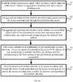
- an apparatus for controlling access of a user terminal includes: a receiving module, configured to: receive an authentication packet sent through an established data tunnel, and transmit the received authentication packet to an obtaining module; the obtaining module, configured to: obtain the authentication packet transmitted by the receiving module, obtain a MAC address in a source MAC address field of the authentication packet, and transmit the obtained MAC address to an authentication module; the authentication module, configured to: receive the MAC address transmitted by the obtaining module, implement access authentication on a user terminal corresponding to the MAC address, and transmit a result of authentication success to a determining module; the determining module, configured to: obtain the result of authentication success transmitted by the authentication module; determine, from a maintained a correspondence between a MAC address of a user terminal and an interface identifier, an interface identifier corresponding to the MAC address of the successfully-authenticated user terminal, where the interface identifier is an interface identifier of an interface on an access switching node connected to the user terminal; and transmit the interface identifier
- the receiving module is further configured to: receive the MAC address of the user terminal sent by the access switching node through the control tunnel, and the interface identifier of the interface on the access switching node connected to the user terminal, where the MAC address of the user terminal and the interface identifier of the interface on the access switching node connected to the user terminal are obtained by the access switching node when the user terminal establishes a connection with the interface on the access switching node, and sends a packet through the connected interface; and transmit the received MAC address and the received interface identifier to an establishing module; and the apparatus further includes the establishing module, configured to: obtain the MAC address and the interface identifier that are transmitted by the receiving module, and establish a correspondence between the MAC address of the user terminal and the interface identifier according to the received MAC address of the user terminal and the received interface identifier.
- an apparatus for controlling access of a user terminal includes: a receiving module, configured to: when a media access control MAC learning function is disabled, receive an authentication packet sent by a user terminal that is connected to an interface on the access switching node, and transmit the authentication packet to an obtaining module; the obtaining module, configured to: receive the authentication packet transmitted by the receiving module, obtain an interface identifier of the interface connected to the user terminal that sends the authentication packet, obtain a MAC address of the user terminal from the received authentication packet, and transmit the interface identifier and the MAC address to a sending module; the sending module, configured to: receive the interface identifier and the MAC address that are transmitted by the obtaining module, and send the obtained MAC address of the user terminal and the obtained interface identifier to a controller through a control tunnel established between the controller and the access switching node, so that the controller maintains a correspondence between the received MAC address of the user terminal and the received interface identifier, where the receiving module is further configured to: receive
- the receiving module is further configured to: receive an access permission that is of the user terminal corresponding to the MAC address and is sent by the controller through the control tunnel, and transmit the access permission to the control module; and the control module is specifically configured to: obtain the access permission transmitted by the receiving module, and configure or modify, according to a received access permission sent by an aggregation switching node, the access permission of the interface that is on the access switching node and corresponding to the interface identifier, to control the user terminal, which is connected to the interface, to access a network according to the access permission.
- the obtaining module specifically includes a signal processor, and is configured to: determine the interface identifier of the interface connected to the user terminal that sends the authentication packet, and obtain the authentication packet transmitted by the receiving module; and the signal processor obtains, from a source MAC address field of the authentication packet, the MAC address of the user terminal that sends the authentication packet.
- an interface identifier corresponding to a MAC address of the successfully-authenticated user terminal is determined from an obtained correspondence between a MAC address of a user terminal and an interface identifier, the determined interface identifier is sent to an access switching node through a control tunnel established between the controller and the access switching node, and the access switching node is instructed to enable an interface corresponding to the interface identifier.
- an interface identifier corresponding to a MAC address of the successfully-authenticated user terminal is determined from an obtained correspondence between a MAC address of a user terminal and an interface identifier, the determined interface identifier is sent to an access switching node through a control tunnel established between the controller and the access switching node, and the access switching node is instructed to enable an interface corresponding to the interface identifier.
- access networks and network access permissions of user terminals can be controlled in a centralized manner, a system architecture is relatively simple and is easy to be implemented, and network security can be further improved.
- the technical solutions provided in the embodiments of the present invention may be implemented by using a controller.
- the controller may be disposed on a network as an independent network device, or may be integrated, as an integrated module, into an aggregation switching node disposed on a network, and details are described in the following respectively.
- Embodiment 1 of the present invention provides a system for controlling access of a user terminal.
- a controller is integrated into an aggregation switching node as an integrated module, to implement technical solutions provided in Embodiment 1 of the present invention.
- the system includes at least one access switching node and at least one aggregation switching node, where each access switching node of the at least one access switching node is connected to one aggregation switching node of the at least one aggregation switching node.
- Any access switching node of the at least one access switching node may be connected to at least one user terminal in a wired manner, or may not be connected to any user terminal, that is, an interface used to connect to a user terminal is in an idle state.
- a packet transmission tunnel is established between an aggregation switching node and an access switching node.
- the packet transmission tunnel between the aggregation switching node and the access switching node may be established according to a preset proprietary protocol or by extending a standard protocol.
- the standard protocol may be the Control And Provisioning of Wireless Access Points (English: Control And Provisioning of Wireless Access Points, CAPWAP for short) protocol.
- CAPWAP Control And Provisioning of Wireless Access Points
- the packet transmission tunnel that is established based on the extended CAPWAP protocol includes a control tunnel for transmitting a control packet and a data tunnel for transmitting a data packet.
- the CAPWAP protocol is a standard protocol applied to a wireless communication environment.
- the CAPWAP protocol is applied to a scenario of interworking between an access control (English: access control, AC for short) node and a wireless access point (English: access point, AP for short).
- the wireless communication environment based on the CAPWAP protocol includes a wireless AP, a network switch, an AC, and a user terminal.
- the wireless AP is connected to at least one user terminal in a wireless manner.
- the packet transmission tunnel for transmitting a packet in a wireless manner is established between the wireless AP and the AC based on the CAPWAP protocol.
- the control tunnel established between the wireless AP and the AC by using the CAPWAP protocol is used to exchange a control packet between the AC and the wireless AP
- the data tunnel established between the wireless AP and the AC by using the CAPWAP protocol is used to carry a data packet sent by a user terminal.
- the data packet transmitted through the data tunnel and the control packet transmitted through the control tunnel may be transmitted in an unencrypted manner.
- the Datagram Transport Layer Security (English: Datagram Transport Layer Security, DTLS) protocol may also be used for encryption, to improve security of the data packet transmitted through the data tunnel and that of the control packet transmitted through the control tunnel.
- that the DTLS protocol is used to encrypt the data packet transmitted through the data tunnel and the control packet transmitted through the control tunnel is used as an example, to further describe structural composition of the data packet and that of the control packet.
- the schematic structural diagram of composition of the data packet transmitted through the data tunnel established by using the CAPWAP protocol is shown in FIG. 3b .
- the data packet includes an IP address header (IP Hdr shown in the diagram), a User Datagram Protocol (English: User Datagram Protocol, UDP for short) header (UDP Hdr shown in the diagram), a DTLS header (DTLS Hdr shown in the diagram), a CAPWAP packet header (CAPWAP Hdr shown in the diagram), and a wireless payload (English: wireless payload), where the wireless payload is used to carry data.
- the CAPWAP Hdr includes a field identifier, a field offset, an optional wireless MAC address field, or other optional wireless information.
- FIG. 3d is a schematic structural diagram of composition of a CAPWAP control packet transmitted through the control tunnel.
- the CAPWAP control packet includes an IP address header (IP Hdr shown in the diagram), a UDP header (UDP Hdr shown in the diagram), a DTLS header (DTLS Hdr shown in the diagram), a CAPWAP packet header (CAPWAP Hdr shown in the diagram), a control header (English: Control Header) field used to carry a function of the control packet, and a message element (English: Message Element) field used to carry content of the control packet.
- the content of the control packet may be called control information.
- the control information carried in the message element field may be type-length-values (English: type-length-value, TLV for short) of different types, where T is a type of the control information, L is a length of the control information, and V is a value of the control information.
- T is a type of the control information
- L is a length of the control information
- V is a value of the control information.
- the value of the control information in the TLV may be extended, that is, in a TLV, multiple extended TLVs may be further included in the value V of the control information, and these extended TLVs may be called level-2 TLVs.
- the TLV is used to perform content extension on the control information.
- a manner of adding a level-2 TLV to the message element in which the value of T is 37 is used to perform content extension on the control message.
- the message element in which the value of T is 37 may be called a No. 37 message element, where a standard format of the No. 37 message element is shown in Table 1.
- values of the vendor identifier field are not the same for different device manufacturers.
- a value 2011 is used as an example for detailed description in the technical solutions provided in this embodiment of the present invention, and the example is still used in the following description.
- the standard format of the No. 37 message element is extended, and an extended format of the message element is shown in Table 2.
- Table 2 Type of message element: 37, information defined by a device vendor, 2 bytes Length of message element: 2 bytes Vendor identifier: a value of 2011, 4 bytes Type 1 of level-2 TLV: 2 bytes Length 1 of level-2 TLV: 2 bytes Content 1 of level-2 TLV: enlarged Type 2 of level-2 TLV: 2 bytes Length 2 of level-2 TLV: 2 bytes Content 2 of level-2 TLV: enlarged >
- the packet transmission tunnel that is established based on the extended CAPWAP protocol includes a control tunnel for transmitting control information and a data tunnel for transmitting data information.
- the transmission tunnel is established between the aggregation switching node and the access switching node based on the extended CAPWAP protocol. That the access switching node is connected to at least one user terminal is used as an example for detailed description.
- the access switching node controls data forwarding of all interfaces.
- the access switching node After a user terminal is connected to an interface on the access switching node, the access switching node obtains an interface identifier of the interface connected to the user terminal, obtains a media access control (English: media access control, MAC for short) address of the user terminal from a received packet sent by the user terminal, and sends the obtained MAC address of the user terminal and the obtained interface identifier to the aggregation switching node through the established packet transmission tunnel.
- the interface identifier of the interface on the access switching node may be preset, or may be a combination form of a device identity of the access switching node and a sequence number (English: sequence number) of the interface.
- interface identifiers of the eight interfaces on the access switching node may be represented as ID1, ID2, ..., and ID8.
- the access switching node may receive a packet sent by the user terminal connected to the interface on the access switching node; determine, by using a signal processor of the access switching node, the interface identifier of the interface connected to the user terminal that sends the packet; extract a source MAC address field of the received packet by using the signal processor, to obtain the MAC address of the user terminal; and send the obtained MAC address of the user terminal and the obtained interface identifier to the aggregation switching node through the control tunnel that is included in the established packet transmission tunnel.
- the signal processor of the access switching node may be a central processing unit (English: central processing unit, CPU for short), a combination of a CPU and a hardware chip, a network processor (English: network processor, NP for short), a combination of a CPU and an NP, or a combination of an NP and a hardware chip.
- CPU central processing unit
- NP network processor
- the aggregation switching node receives the MAC address of the user terminal and the interface identifier of the interface on the access switching node connected to the user terminal, where the MAC address of the user terminal and the interface identifier are sent by the access switching node through the packet transmission tunnel; and maintains a correspondence between the MAC address of the user terminal and the interface identifier according to the received MAC address of the user terminal and the received interface identifier.
- the correspondence between the MAC address of the user terminal and the interface identifier that is maintained by the aggregation switching node may be stored in a buffering manner. The correspondence is stored within a period of time; after access authentication implemented on the user terminal is complete, the maintained correspondence between the MAC address of the user terminal and the interface identifier may be deleted.
- the access switching node has a MAC learning (English: MAC learning) function.
- MAC learning allows a network switch to learn a MAC address of another device on a network, to identify an interface from which a packet whose destination address is the MAC address is sent.
- the aggregation switching node implements control on access of the user terminal, if the MAC learning function of the access switching node is not disabled, the user terminal can access, without being authenticated, a network by using the access switching node. In this case, access of the user terminal cannot be controlled.
- the MAC learning function of the access switching node is disabled.
- the user terminal In a case in which the MAC learning function is disabled, the user terminal cannot directly access a network, and the access switching node cannot find, according to the MAC address of the user terminal, the interface identifier of the interface connected to the user terminal. Therefore, in this embodiment of the present invention, the correspondence between the MAC address of the user terminal and the interface identifier is maintained by the aggregation switching node.
- the access switching node can determine, by using a signal processor of the access switching node such as a CPU or an NP and in a software manner, the interface identifier of the interface that receives the packet, successfully learn the MAC address of the user terminal from the packet sent by the user terminal, and further implement control on access of the user terminal by using the learned MAC address of the user terminal.
- a signal processor of the access switching node such as a CPU or an NP
- the interface identifier of the interface that receives the packet, successfully learn the MAC address of the user terminal from the packet sent by the user terminal, and further implement control on access of the user terminal by using the learned MAC address of the user terminal.
- the access switching node receives the packet sent by the user terminal that is connected to the interface on the access switching node in a wired manner; encapsulates the packet based on the protocol for establishing the packet transmission tunnel; and then forwards the encapsulated packet to the aggregation switching node based on the established packet transmission tunnel. For example, the access switching node encapsulates, based on the CAPWAP protocol, the received packet sent by the user terminal, and then sends the encapsulated packet to the aggregation switching node.
- the aggregation switching node receives the packet that is sent by the user terminal and forwarded by the access switching node, decapsulates the received packet, and implements, according to the decapsulated packet, access authentication on the user terminal that sends the packet. For example, when the aggregation switching node receives the packet that is encapsulated based on the CAPWAP protocol and is transmitted through the packet transmission tunnel established based on the CAPWAP protocol, the aggregation switching node also decapsulates the received packet based on the CAPWAP protocol, and implements, according to the decapsulated packet, authentication on the user terminal that sends the packet.
- the aggregation switching node After successfully implementing the access authentication on the user terminal, the aggregation switching node determines, from the maintained correspondence between the MAC address of the user terminal and the interface identifier of the interface on the access switching node connected to the user terminal, the interface identifier corresponding to the MAC address of the successfully-authenticated user terminal, and sends the determined interface identifier to the access switching node.
- the aggregation switching node may further determine an access permission of the user terminal, and send the determined access permission of the user terminal to the access switching node together with the determined interface identifier.
- the access permission may be one or more of the following access permissions:
- the access switching node receives the interface identifier sent by the aggregation switching node, determines, according to the received interface identifier, the interface that is on the access switching node and corresponding to the interface identifier, and implements control on access of the user terminal by controlling the determined interface.
- the foregoing step may include that the access switching node may enable, according to the interface identifier sent by the aggregation switching node, the interface corresponding to the received interface identifier, and allows the user terminal, which is connected to the interface, to access a network.
- the access switching node determines, according to the received interface identifier, the interface that is on the access switching node and corresponding to the interface identifier, and implements control on access of the user terminal by controlling the determined interface; or may configure or modify, according to the received access permission sent by the aggregation switching node, an access permission of the interface that is on the access switching node and corresponding to the interface identifier, to control the user terminal, which is connected to the interface, to access a network according to the access permission.
- the packet sent by the user terminal may be an Institute of Electrical and Electronics Engineers (English: Institute of Electrical and Electronics Engineers, IEEE for short) 802.1x packet, or another type of packet such as an Address Resolution Protocol (English: Address Resolution Protocol, ARP for short) packet or a Dynamic Host Configuration Protocol (English: Dynamic Host Configuration Protocol, DHCP for short) packet.
- IEEE 802.1x packet uses an IEEE 802.1x packet as an example to describe in detail the technical solutions provided in Embodiment 1 of the present invention.
- Access authentication on the user terminal is implemented based on the IEEE 802.1x packet sent by the user terminal.
- the packet transmission tunnel that includes the control tunnel and the data tunnel is established, based on the extended CAPWAP protocol, between the aggregation switching node and the access switching node.
- the packet transmission tunnel that is established, based on the CAPWAP protocol, between the aggregation switching node and the access switching node includes the control tunnel and the data tunnel.
- the access switching node sends attribute information of the access switching node to the aggregation switching node through the established control tunnel.
- the attribute information of the access switching node includes an identifier of the access switching node, for example, a MAC address of the access switching node, which may be represented as switch MAC.
- the attribute information of the access switching node may further include version information of firmware of the access switching node, which may be represented as TYPE_SWITCH_VERSION.
- the attribute information may be implemented by extending the No. 37 message element among message elements in the CAPWAP control packet. The extended No.
- a message element field in the control packet transmitted through the control tunnel is used to carry control information, where the message element may be TLVs of different types.
- the TLV is used to perform content extension on the control information.
- a manner of adding a level-2 TLV to the message element in which the value of T is 37 is used to perform content extension on the control message.
- the message element in which the value of T is 37 may be called a No. 37 message element, where a standard format of the No. 37 message element is shown in the foregoing Table 1.
- the aggregation switching node maintains a correspondence between the packet transmission tunnel, which is established based on the CAPWAP protocol, and an identifier of the access switching node such as Switch MAC.
- the aggregation switching node may maintain a correspondence between the packet transmission tunnel 1 and Switch 23.
- the access switching node whose identifier is Switch 23 sends a packet to the aggregation switching node through the established packet transmission tunnel subsequently, and when the aggregation switching node processes or responds to the packet, the aggregation switching node may determine, from the maintained correspondence between the packet transmission tunnel 1 and Switch 23, a device that sends the packet through the packet transmission channel, and a packet transmission channel through which response information is transmitted to the access switching node.
- content included in the No. 37 message element in the extended CAPWAP control packet of the access switching node may be shown in Table 3.
- the aggregation switching node For the packet transmission tunnel that is established based on the CAPWAP protocol, the aggregation switching node sets a manner of authenticating each access switching node to IEEE 802.1x-based authentication. Exemplarily, the aggregation switching node may further set a manner of authenticating an interface on each access switching node to IEEE 802.1x-based authentication.
- the access switching node When a connection is established between the user terminal and the interface on the access switching node, the access switching node receives the 802.1x packet sent by the user terminal, obtains the interface identifier of the interface connected to the user terminal that sends the 802.1x packet, and obtains the MAC address of the user terminal from the received 802. 1x packet sent by the user terminal.
- the access switching node sends the obtained MAC address of the user terminal and the obtained interface identifier to the aggregation switching node through the packet transmission tunnel established based on the CAPWAP protocol.
- the packet transmission tunnel that is established based on the CAPWAP protocol includes the control tunnel and the data tunnel, where the control tunnel may be used to transmit the CAPWAP control packet, and the data tunnel may be used to transmit the CAPWAP data packet. Therefore, the access switching node may send the obtained MAC address of the user terminal and the obtained interface identifier to the aggregation switching node through the control tunnel.
- the access switching node may send, based on an extended level-2 TLV, the obtained MAC address of the user terminal and the obtained interface identifier to the aggregation switching node, where the extended level-2 TLV is shown in Table 4.
- USER_MAC shown in Table 4 is the MAC address of the user terminal, and interface index is the interface identifier.
- Type of message element 37, 2 bytes Length of message element: 2 bytes Vendor identifier: a value of 2011, 4 bytes Type 1 of level-2 TLV: TYPE_USER_MAC, 2 bytes Length 1 of level-2 TLV: 0x06, 2 bytes Content 1 of level-2 TLV: USER MAC Type 2 of level-2 TLV: TYPE_USER_SWITCH_IF, 2 bytes Length 2 of level-2 TLV: 0x04, 2 bytes Content 2 of level-2 TLV: interface index
- the access switching node captures, on the interface of the access switching node, the IEEE 802.1x packet sent by the user terminal, sends the captured IEEE 802.1x packet to the aggregation switching node through the packet transmission channel established based on the CAPWAP protocol.
- the packet transmission tunnel that is established based on the CAPWAP protocol includes the control tunnel and the data tunnel, where the control tunnel may be used to transmit the CAPWAP control packet, and the data tunnel may be used to transmit the CAPWAP data packet.
- the access switching node may send the encapsulated IEEE 802.1x packet to the aggregation switching node through the data tunnel.
- the aggregation switching node receives the MAC address of the user terminal and the interface identifier, and maintains the correspondence between the MAC address of the user terminal and the interface identifier.
- a MAC address of the user terminal and an interface identifier that is a MAC address and an interface number of the access switching node, are used as an example for detailed description.
- a user terminal 1 and an access switching node 1 shown in FIG. 2 are used as an example for detailed description. It is assumed that an identifier of the user terminal 1 is UE MAC1, an identifier of the access switching node 1 is AP MAC1, and the access switching node 1 provides a total of eight access interfaces numbered from 1 to 8. If the user terminal 1 is connected to the second interface, the interface identifier of the interface is AP MAC1-2.
- the access switching node 1 When the user terminal 1 is connected to the access switching node 1, the user terminal 1 sends a packet, and the access switching node obtains the interface identifier AP MAC1-2 of the interface connected to the user terminal 1.
- the access switching node 1 captures the packet sent by the user terminal 1, uses a signal processor of the access switching node 1 to analyze the captured packet, to obtain the identifier UE MAC1 of the user terminal 1 in the packet, and sends the obtained UE MAC1 and AP MAC1-2 to the aggregation switching node through the control tunnel by extending the No. 37 message element in the CAPWAP control packet.
- the identifier of the terminal and the interface identifier that are received by the aggregation switching node are respectively UE MAC1 and AP MAC1-2 is used as an example for detained description.
- the aggregation switching node receives UE MAC1 and AP MAC1-2 that are sent by the access switching node, and establishes and buffers a correspondence between UE MAC1 and AP MAC1-2.
- the access switching node receives the IEEE 802.1x packet sent by the user terminal, encapsulates the received IEEE 802.1x packet based on the CAPWAP protocol, and then sends the encapsulated packet to the aggregation switching node through the data tunnel.
- the aggregation switching node receives the IEEE 802.1x packet encapsulated based on the CAPWAP protocol, decapsulates the received IEEE 802.1x packet that is encapsulated based on the CAPWAP protocol, and implements access authentication according to the decapsulated IEEE 802.1x packet.
- the aggregation switching node may further limit permission information of the user terminal. After authentication succeeds, the aggregation switching node determines the access permission of the user terminal.
- the aggregation switching node determines, from the maintained correspondence between the MAC address of the user terminal and the interface identifier of the interface on the access switching node connected to the user terminal, an interface identifier corresponding to the MAC address of the successfully-authenticated user terminal, and sends the determined interface identifier to the access switching node.
- the aggregation switching node may further send the determined access permission of the user terminal to the access switching node together with the determined interface identifier.
- the extended level-2 TLV may be shown in Table 5.
- USER VLAN is used to indicate a VLAN that can be accessed by the user terminal;
- a Rule field is used to indicate the access permission of the user terminal.
- the access switching node may further control, according to the received access permission delivered by the aggregation switching node, the interface corresponding to the interface identifier, to implement control on the access permission of the user terminal.
- the aggregation switching node that has a packet forwarding function is used as an example for detailed description.
- the controller disposed independently in the system may be further used to implement the technical solutions to control access of the user terminal.
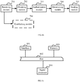
- a system architecture shown in FIG. 4 includes at least one controller (English: controller) that is disposed independently, at least one access switching node, and at least one packet forwarding device.
- the packet forwarding device may be an aggregation switching node.
- the controller may be directly connected to the aggregation switching node, or may be connected to the aggregation switching node by using a router that is disposed.
- Each access switching node of the at least one access switching node is connected to one aggregation switching node of the at least one aggregation switching node.
- Any access switching node of the at least one access switching node may be connected to at least one user terminal in a wired manner, or may not be connected to any user terminal, that is, an interface used to connect to a user terminal is in an idle state.
- a packet transmission tunnel is established between the controller and the access switching node.
- the packet transmission tunnel between the controller and the access switching node may be established according to a preset proprietary protocol or by extending a standard protocol.
- the standard protocol may be the CAPWAP protocol.
- that a packet transmission tunnel is established by extending the CAPWAP protocol is used as an example for detailed description.
- the packet transmission tunnel that is established based on the extended CAPWAP protocol includes a control tunnel for transmitting control information and a data tunnel for transmitting data information.
- the access switching node After the packet transmission tunnel is established based on the CAPWAP protocol, when a user terminal is connected to an interface on the access switching node and sends a packet, the access switching node obtains an interface identifier of the interface that receives the packet, that is, an interface identifier of the interface connected to the user terminal that sends the packet; obtains a MAC address of the user terminal from the received packet; and sends the obtained MAC address of the user terminal and the obtained interface identifier to the controller through the established packet transmission tunnel.
- the interface identifier of the interface on the access switching node may be preset, or may be a combination form of a device identity of the access switching node and a sequence number of the interface.
- the access switching node may receive a packet sent by the user terminal connected to the interface on the access switching node; determine, by using a signal processor of the access switching node, the interface identifier of the interface connected to the user terminal that sends the packet; extract a source MAC address field of the received packet by using the signal processor, to obtain the MAC address of the user terminal; and send the obtained MAC address of the user terminal and the obtained interface identifier to the aggregation switching node through the control tunnel that is included in the established packet transmission tunnel.
- the signal processor of the access switching node may be a CPU, a combination of a CPU and a hardware chip, an NP, a combination of a CPU and an NP, or a combination of an NP and a hardware chip.
- the controller receives the MAC address of the user terminal and the interface identifier of the interface on the access switching node connected to the user terminal, where the MAC address of the user terminal and the interface identifier are sent by the access switching node through the packet transmission tunnel; and maintains a correspondence between the MAC address of the user terminal and the interface identifier according to the received MAC address of the user terminal and the received interface identifier.
- the correspondence between the MAC address of the user terminal and the interface identifier that is maintained by the controller may be stored in a buffering manner. The correspondence is stored within a period of time; after access authentication implemented on the user terminal is complete, the maintained correspondence between the MAC address of the user terminal and the interface identifier may be deleted.
- the access switching node receives the packet sent by the user terminal that is connected to the interface on the access switching node in a wired manner; encapsulates the packet based on the protocol that is used to establish the packet transmission tunnel; and then forwards the encapsulated packet to the controller through the established packet transmission tunnel.
- the access switching node encapsulates, based on the CAPWAP protocol, the received packet that is sent by the user terminal, and then sends the encapsulated packet to the controller.
- the controller receives the packet that is sent by the user terminal and forwarded by the access switching node, decapsulates the received packet, and implements, according to the decapsulated packet, access authentication on the user terminal that sends the packet. For example, when the controller receives the packet that is encapsulated based on the CAPWAP protocol and is transmitted through the packet transmission tunnel established based on the CAPWAP protocol, the controller also decapsulates the received packet based on the CAPWAP protocol, and implements, according to the decapsulated packet, authentication on the user terminal that sends the packet.
- the controller After successfully implementing the access authentication on the user terminal, the controller determines, from the maintained correspondence between the MAC address of the user terminal and the interface identifier of the interface on the access switching node connected to the user terminal, the interface identifier corresponding to the MAC address of the successfully-authenticated user terminal, and sends the determined interface identifier to the access switching node.
- the controller may further determine an access permission of the user terminal, and send the determined access permission of the user terminal to the access switching node together with the determined interface identifier.
- the access permission may be one or more of the following access permissions:
- the access switching node When receiving the interface identifier sent by the controller, the access switching node determines, according to the received interface identifier, the interface that is on the access switching node and corresponding to the interface identifier, and implements control on access of the user terminal by controlling the determined interface.
- the foregoing step may include that the access switching node may enable, according to the interface identifier sent by the aggregation switching node, the interface corresponding to the received interface identifier, and allows the user terminal, which is connected to the interface, to access a network.
- the access switching node may further determine, according to the received interface identifier, the interface that is on the access switching node and corresponding to the interface identifier, and implement control on access of the user terminal by controlling the determined interface; or may configure or modify, according to the received access permission sent by the aggregation switching node, an access permission of the interface that is on the access switching node and corresponding to the interface identifier, to control the user terminal, which is connected to the interface, to access a network according to the access permission.
- the packet sent by the user terminal may be an IEEE 802.1x packet, or another type of packet such as an ARP packet or a DHCP packet.
- Embodiment 2 of the present invention provides a method for controlling access of a user terminal. As shown in FIG. 5 , a specific processing procedure of the method is as follows:
- the packet transmission tunnel between the aggregation switching node and the access switching node may be established according to a preset proprietary protocol or by extending a standard protocol.
- the standard protocol may be the CAPWAP protocol.
- that a packet transmission tunnel is established by extending the CAPWAP protocol is used as an example for detailed description.
- the packet transmission tunnel that is established based on the extended CAPWAP protocol includes a control tunnel for transmitting control information and a data tunnel for transmitting data information.
- Step 52 The access switching node obtains a MAC address of a user terminal connected to an interface on the access switching node and an interface identifier of the interface connected to the user terminal.
- the user terminal is connected to the interface on the access switching node in a wired manner, and sends a packet.
- the access switching node When the user terminal is connected to the interface on the access switching node and sends a packet, the access switching node obtains the interface identifier of the interface connected to the user terminal, captures the packet sent by the user terminal, obtains the MAC address of the user terminal from the captured packet, and sends the obtained MAC address of the user terminal and the obtained interface identifier to the aggregation switching node through the established packet transmission tunnel.
- the interface identifier of the interface on the access switching node may be preset, or may be a combination form of a device identity of the access switching node and a sequence number of the interface.
- the access switching node may receive a packet sent by the user terminal connected to the interface on the access switching node; determine, by using a signal processor of the access switching node, the interface identifier of the interface connected to the user terminal that sends the packet; extract a source MAC address field of the received packet by using the signal processor, to obtain the MAC address of the user terminal; and send the obtained MAC address of the user terminal and the obtained interface identifier to the aggregation switching node through the control tunnel that is included in the established packet transmission tunnel.
- the signal processor of the access switching node may be a CPU, a combination of a CPU and a hardware chip, an NP, a combination of a CPU and an NP, or a combination of an NP and a hardware chip.
- the packet that is sent by the user terminal and captured by the access switching node may include an IEEE 802.1x packet, an ARP packet, or a DHCP packet.
- Step 53 The access switching node sends the obtained interface identifier and the obtained MAC address of the user terminal to the aggregation switching node through the established packet transmission tunnel.
- the packet transmission tunnel that is established based on the CAPWAP protocol includes the control tunnel and the data tunnel, where the control tunnel may be used to transmit a control packet, and the data tunnel may be used to transmit a data packet. Therefore, the access switching node may send the obtained MAC address of the user terminal and the obtained interface identifier to the aggregation switching node through the control tunnel. The access switching node may send, based on an extended level-2 TLV, the obtained MAC address of the user terminal and the obtained interface identifier to the aggregation switching node.
- the extended level-2 TLV is described in the foregoing Table 4.
- Step 54 The aggregation switching node receives the MAC address of the user terminal and the interface identifier that are sent by the access switching node, and maintains a correspondence between the MAC address of the user terminal and the interface identifier.
- the correspondence between the MAC address of the user terminal and the interface identifier that is maintained by the aggregation switching node may be stored in a buffering manner.
- the correspondence is stored within a period of time; after access authentication implemented on the user terminal is complete, the maintained correspondence between the MAC address of the user terminal and the interface identifier may be deleted.
- Step 55 The access switching node captures, on the interface of the access switching node, a packet sent by the user terminal, and sends the captured packet to the aggregation switching node through the packet transmission channel established based on the CAPWAP protocol.
- the packet transmission tunnel that is established based on the CAPWAP protocol includes the control tunnel and the data tunnel, where the control tunnel may be used to transmit a control packet, and the data tunnel may be used to transmit a data packet.
- the access switching node may encapsulate the captured packet based on the CAPWAP protocol, and then send the encapsulated packet to the aggregation switching node through the data tunnel.
- Step 56 The aggregation switching node receives the packet that is sent through the packet transmission tunnel, decapsulates the received packet, obtains the MAC address of the user terminal, and implements access authentication on the user terminal.
- the aggregation switching node receives the packet encapsulated based on the CAPWAP protocol, decapsulates the received packet that is encapsulated based on the CAPWAP protocol, and implements access authentication according to the decapsulated packet.
- Step 57 After authentication succeeds, the aggregation switching node determines, from the maintained correspondence between the MAC address of the user terminal and the interface identifier of the interface on the access switching node connected to the user terminal, the interface identifier corresponding to the MAC address of the successfully-authenticated user terminal, and sends the determined interface identifier to the user terminal.
- the aggregation switching node may further determine an access permission of the user terminal, and send the determined access permission of the user terminal to the access switching node together with the determined interface identifier.
- An authentication success message sent by the aggregation switching node to the access switching node may include information such as the MAC address of the user terminal, the interface identifier, and the access permission of the user terminal, and the information may be sent to the access switching node by using the extended level-2 TLV.
- the extended level-2 TLV may be described in the foregoing Table 5.
- Step 58 The access switching node receives the interface identifier sent by the aggregation switching node, enables the interface corresponding to the interface identifier, and implements control on access of the user terminal by controlling the determined interface.
- the access switching node may enable, according to the interface identifier sent by the aggregation switching node, the interface corresponding to the received interface identifier, and allow the user terminal, which is connected to the interface, to access a network for packet transmission.
- the access switching node may further receive the access permission that is corresponding to the user terminal and is sent by the aggregation switching node; and control, by controlling the interface connected to the user terminal, the user terminal to access a network according to the received access permission.
- the packet sent by the user terminal may be an IEEE 802.1x packet, or another type of packet such as an ARP packet or a DHCP packet.
- an embodiment of the present invention provides a method for controlling access of a user terminal.
- a specific processing procedure of the method is as follows:
- the aggregation switching node may establish the packet transmission tunnel with the access switching node based on a proprietary protocol or based on extension of a standard protocol.
- the packet transmission tunnel is established between the controller and the access switching node based on extension of the CAPWAP protocol.
- the aggregation switching node maintains a correspondence between the established packet transmission tunnel and the access switching node. For example, it is assumed that the identifier of the access switching node is Switch 23, after a packet transmission tunnel 1 is established between the aggregation switching node and the access switching node whose identifier is Switch 23, the aggregation switching node may maintain a correspondence between the packet transmission tunnel 1 and Switch 23.
- the aggregation switching node may determine, from the maintained correspondence between the packet transmission tunnel 1 and Switch 23, a device that sends the packet, a packet transmission channel through which the packet is sent, an access switching node to which the packet shall be transmitted, and a packet transmission channel through which response information shall be transmitted.
- Step 62 The aggregation switching node receives an authentication packet sent by the access switching node through the established data tunnel.
- the packet sent by the access switching node is a packet that is sent by the user terminal connected to an interface on the access switching node and is captured on the interface by the access switching node.
- the captured packet is sent to the aggregation switching node after being encapsulated based on the CAPWAP protocol.
- the packet captured by the access switching node may be an 802.1x packet, an ARP packet, or a DHCP packet.
- Step 63 The aggregation switching node obtains a MAC address in a source MAC address field of the authentication packet, and implements access authentication on a user terminal corresponding to the obtained MAC address.
- Step 64 After the access authentication implemented on the user terminal succeeds, determine, from a maintained correspondence between a MAC address of a user terminal and an interface identifier, an interface identifier corresponding to the MAC address of the successfully-authenticated user terminal.
- a correspondence between a MAC address of a user terminal and an interface identifier of the access switching node connected to the user terminal may be determined in the following manner: receiving the MAC address of the user terminal that is sent by the access switching node through the control tunnel, and the interface identifier of the interface on the access switching node connected to the user terminal, where the MAC address of the user terminal and the interface identifier of the interface on the access switching node connected to the user terminal are obtained by the access switching node when the user terminal establishes a connection with the interface on the access switching node, and sends a packet through the connected interface; and establishing a correspondence between the MAC address of the user terminal and the interface identifier according to the received MAC address of the user terminal and the received interface identifier.
- the correspondence between the MAC address of the user terminal and the interface identifier that is maintained by the aggregation switching node may be stored in a buffering manner.
- the correspondence is stored within a period of time; after the access authentication implemented on the user terminal is complete, the correspondence between the MAC address of the user terminal and the interface identifier may be deleted.
- the correspondence between a MAC address of a user terminal and an interface identifier refer to the detailed description in Embodiment 1 and Embodiment 2, and details are not described in Embodiment 3 of the present invention again.
- Step 65 Send the determined interface identifier to the access switching node through the control tunnel established between the controller and the access switching node, and instruct the access switching node to enable the interface corresponding to the interface identifier.
- the access authentication implemented on the user terminal may further include determining an access permission of the user terminal.
- the aggregation switching node sends the determined access permission of the user terminal to the access switching node through the control tunnel, to instruct the access switching node to control, according to the access permission, the user terminal to pass through the interface identifier.
- Embodiment 3 of the present invention further provides an apparatus for controlling access of a user terminal.
- the apparatus includes:
- the foregoing receiving module 701 is further configured to: receive the MAC address of the user terminal sent by the access switching node through the control tunnel, and the interface identifier of the interface on the access switching node connected to the user terminal, where the MAC address of the user terminal and the interface identifier of the interface on the access switching node connected to the user terminal are obtained by the access switching node when the user terminal establishes a connection with the interface on the access switching node, and sends a packet through the connected interface; and transmit the received MAC address and the received interface identifier to an establishing module 706.
- the apparatus further includes the establishing module 706, configured to: obtain the MAC address and the interface identifier that are transmitted by the receiving module 705, and establish a correspondence between the MAC address of the user terminal and the interface identifier according to the received MAC address of the user terminal and the received interface identifier.
- Embodiment 3 of the present invention further provides a network switch.
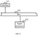
- the network switch includes: an interface 801, a memory 803, and a signal processor 804.
- the interface 801 is configured to: receive an authentication packet sent through an established data tunnel, and transmit the received authentication packet to the signal processor 804 through a bus 802.
- the interface 801 may be one or more of the following: a network interface controller (English: network interface controller, NIC for short) that provides a wired interface, for example, an Ethernet NIC that may provide a copper wire interface and/or a fiber interface; a NIC that provides a wireless interface, for example, a wireless local area network (English: wireless local area network, WLAN for short) NIC.
- a network interface controller English: network interface controller, NIC for short
- NIC network interface controller
- NIC wireless local area network
- WLAN wireless local area network
- the memory 803 is configured to: store program code, and store a correspondence between a MAC address of a user terminal and an interface identifier, and transmit the stored program code to the signal processor 804 through the bus 802.
- the memory 803 may be a volatile memory (English: volatile memory), for example, a random-access memory (English: random-access memory, RAM for short); or a non-volatile memory (English: non-volatile memory), for example, a flash memory (English: flash memory), a hard disk drive (English: hard disk drive, HDD for short) or a solid-state drive (English: solid-state drive, SSD for short); or a combination of memories of the foregoing types.
- a volatile memory for example, a random-access memory (English: random-access memory, RAM for short
- a non-volatile memory for example, a flash memory (English: flash memory), a hard disk drive (English: hard disk drive, HDD for short) or a solid-state drive (English: solid-state drive, SSD for short) or a combination of memories of the foregoing types.
- the signal processor 804 is configured to: obtain, by using the bus 802, the program code stored in the memory 803, and execute the following according to the obtained program code: obtaining the MAC address in a source MAC address field of the authentication packet; implementing access authentication on the user terminal corresponding to the MAC address; after the access authentication succeeds, obtaining the correspondence between the MAC address of the user terminal and the interface identifier that is stored in the memory 803; determining, from the obtained correspondence between the MAC address of the user terminal and the interface identifier, an interface identifier corresponding to the MAC address of the successfully-authenticated user terminal, where the interface identifier is an interface identifier of the interface on an access switching node connected to the user terminal; and transmitting the interface identifier to the interface 801 through the bus 802.
- the signal processor 804 may be a central processing unit (English: central processing unit, CPU for short), a combination of a CPU and a hardware chip, a network processor (English: network processor, NP for short), a combination of a CPU and an NP, or a combination of an NP and a hardware chip.
- CPU central processing unit
- NP network processor
- the foregoing hardware chip may be one or a combination of the following chips: an application-specific integrated circuit (English: application-specific integrated circuit, ASIC for short), a field-programmable gate array (English: field-programmable gate array, FPGA for short), and a complex programmable logical device (English: complex programmable logic device, CPLD for short).
- ASIC application-specific integrated circuit
- FPGA field-programmable gate array
- CPLD complex programmable logic device
- the foregoing interface 801 is further configured to: obtain, by using the bus 802, the interface identifier transmitted by the signal processor 804, send the determined interface identifier to the access switching node through a control tunnel established between the controller and the access switching node, and instruct the access switching node to enable the interface corresponding to the interface identifier.
- the foregoing interface 801 is further configured to: receive the MAC address of the user terminal sent by the access switching node through the control tunnel, and the interface identifier of an interface on the access switching node connected to the user terminal, where the MAC address of the user terminal and the interface identifier of the interface on the access switching node connected to the user terminal are obtained by the access switching node when the user terminal establishes a connection with the interface on the access switching node, and sends a packet through the connected interface; and transmit the received MAC address and the received interface identifier to the signal processor 804 through the bus.
- the signal processor 804 is further configured to: obtain, by using the bus 802, the MAC address and the interface identifier that are transmitted by the interface 801; establish a correspondence between the MAC address of the user terminal and the interface identifier according to the received MAC address of the user terminal and the received interface identifier; and transmit the established correspondence between the MAC address and the interface identifier to the memory 803 through the bus 802.
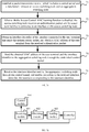
- Embodiment 3 of the present invention provides a method for controlling access of a user terminal.
- a specific processing procedure of the method is as follows:
- the aggregation switching node may establish the packet transmission tunnel with the access switching node based on a proprietary protocol or based on extension of a standard protocol.
- the packet transmission tunnel is established between the controller and the access switching node based on extension of the CAPWAP protocol.
- the aggregation switching node maintains a correspondence between the established packet transmission tunnel and the access switching node. For example, it is assumed that the identifier of the access switching node is Switch 23, after a packet transmission tunnel 1 is established between the aggregation switching node and the access switching node whose identifier is Switch 23, the aggregation switching node may maintain a correspondence between the packet transmission tunnel 1 and Switch 23.
- the aggregation switching node may determine, from the maintained correspondence between the packet transmission tunnel 1 and Switch 23, a device that sends the packet, a packet transmission channel through which the packet is sent, an access switching node to which the packet shall be transmitted, and a packet transmission channel through which response information shall be transmitted.
- Step 72 When a Media Control Access MAC learning function is disabled, the access switching node receives an authentication packet sent by a user terminal that is connected to an interface on the access switching node.
- Step 73 Obtain an interface identifier of the interface connected to the user terminal that sends the authentication packet, and obtain a MAC address of the user terminal from the received authentication packet.
- the access switching node determines, by using a signal processor that is capable of performing a processing function according to program code, the interface identifier of the interface connected to the user terminal that sends the authentication packet, and transmits the received authentication packet to the signal processor of the access switching node; and the signal processor obtains, from a source MAC address field of the authentication packet, the MAC address of the user terminal that sends the authentication packet.
- Step 74 Send the obtained MAC address of the user terminal and the obtained interface identifier to the aggregation switching node through the established control tunnel.
- Step 75 Receive the interface identifier sent by the aggregation switching node through the control tunnel, and enable, according to the received interface identifier, the interface corresponding to the interface identifier.
- the interface identifier is an interface identifier that is determined, after the aggregation switching node successfully implements access authentication on the user terminal, from a maintained correspondence between the MAC address of the user terminal and the interface identifier of the interface on the access switching node connected to the user terminal, and is corresponding to the MAC address of the successfully-authenticated user terminal.
- Embodiment 3 of the present invention further provides an apparatus for controlling access of a user terminal. As shown in FIG. 7b , the apparatus includes:
- the foregoing receiving module 901 is further configured to: receive an access permission that is of the user terminal corresponding to the MAC address and is sent by the controller through the control tunnel, and transmit the access permission to the control module; and the control module 904 is specifically configured to: obtain the access permission transmitted by the receiving module 901, and configure or modify, according to a received access permission sent by an aggregation switching node, the access permission of the interface that is on the access switching node and corresponding to the interface identifier, to control the user terminal, which is connected to the interface, to access a network according to the access permission.
- the foregoing obtaining module 902 specifically includes a signal processor, and is configured to: determine the interface identifier of the interface connected to the user terminal that sends the authentication packet, and obtain the authentication packet transmitted by the receiving module; and the signal processor obtains, from a source MAC address field of the authentication packet, the MAC address of the user terminal that sends the authentication packet.
- Embodiment 3 of the present invention further provides a network switch.
- the network switch includes: an interface 101 and a signal processor 103.
- the interface 101 is configured to: when a media access control MAC learning function is disabled, receive an authentication packet sent by a user terminal that is connected to an interface on the access switching node, and transmit the authentication packet to the signal processor 103 through a bus 102.
- the interface 101 may be one or more of the following: a NIC that provides a wired interface, for example, an Ethernet NIC that may provide a copper wire interface and/or a fiber interface.
- the signal processor 103 is configured to: receive, through the bus 102, the authentication packet transmitted by the interface 101, obtain an interface identifier of the interface connected to the user terminal that sends the authentication packet, obtain a MAC address of the user terminal from the received authentication packet, and transmit the interface identifier and the MAC address to the interface 101 through the bus 102.
- the signal processor 103 may be a CPU, a combination of a CPU and a hardware chip, an NP, a combination of a CPU and an NP, or a combination of an NP and a hardware chip.
- the foregoing hardware chip may be one or a combination of the following chips: ASIC, FPGA, CPLD, and the like.
- a relay may further include a memory, where the memory is configured to store program code.
- the signal processor obtains the stored program code from the memory, and performs corresponding processing according to the obtained program code.
- the memory may be a volatile memory, for example, an random-access memory; or a non-volatile memory, for example, a read-only memory (English: read-only memory, ROM for short), a flash memory, a hard disk drive or a solid-state drive; or a combination of memories of the foregoing types.
- a volatile memory for example, an random-access memory
- a non-volatile memory for example, a read-only memory (English: read-only memory, ROM for short), a flash memory, a hard disk drive or a solid-state drive; or a combination of memories of the foregoing types.
- the foregoing interface 101 is further configured to: receive, through the bus 102, the interface identifier and the MAC address that are transmitted by the signal processor 103, and send the obtained MAC address of the user terminal and the obtained interface identifier to a controller through an established control tunnel, so that the controller maintains a correspondence between the received MAC address of the user terminal and the received interface identifier.
- the foregoing interface 101 is further configured to: receive the interface identifier sent by the controller through the control tunnel, and transmit the interface identifier to the signal processor 103 through the bus 102, where the interface identifier is an interface identifier that is determined from the correspondence between the MAC address of the user terminal and the interface identifier after the controller successfully implements access authentication on the user terminal corresponding to the MAC address, and is corresponding to the MAC address of the successfully-authenticated user terminal.
- the signal processor 103 is configured to: obtain, by using the bus 102, the interface identifier transmitted by the interface 101, and enable, according to the received interface identifier, the interface corresponding to the interface identifier.
- the interface 101 is further configured to: receive an access permission that is of the user terminal corresponding to the MAC address and is sent by the controller through the control tunnel, and transmit the access permission to the signal processor 103 through the bus 102.
- the signal processor 103 is specifically configured to: obtain the access permission transmitted by the interface 101 through the bus 102, and configure or modify, according to a received access permission, the access permission of the interface that is on the access switching node and corresponding to the interface identifier, to control the user terminal, which is connected to the interface, to access a network according to the access permission.
- the foregoing signal processor 103 is configured to: determine the interface identifier of the interface connected to the user terminal that sends the authentication packet, and obtain the authentication packet transmitted by the interface 101; and the signal processor 103 obtains, from a source MAC address field of the authentication packet, the MAC address of the user terminal that sends the authentication packet.
- centralized control on access of user terminals can be implemented on an aggregation switching node, and distributed policy control can be implemented on an access switching node, to control data forwarding functions of user terminals at an access layer while implementing centralized management of the user terminals.
- distributed policy control can be implemented on an access switching node, to control data forwarding functions of user terminals at an access layer while implementing centralized management of the user terminals.
- the embodiments of the present invention may be provided as a method, an apparatus (device), or a computer program product. Therefore, the present invention may use a form of hardware only embodiments, software only embodiments, or embodiments with a combination of software and hardware. Moreover, the present invention may use a form of a computer program product that is implemented on one or more computer-usable storage media (including but not limited to a disk memory, an optical read-only memory, an optical memory, and the like) that include computer-usable program code.
- computer-usable storage media including but not limited to a disk memory, an optical read-only memory, an optical memory, and the like
- These computer program instructions may be provided for a general-purpose computer, a dedicated computer, an embedded processor, or a processor of any other programmable data processing device to generate a machine, so that the instructions executed by a computer or a processor of any other programmable data processing device generate an apparatus for implementing a specified function in one or more procedures in the flowcharts and/or in one or more blocks in the block diagrams.
- These computer program instructions may also be stored in a computer readable memory that can instruct the computer or any other programmable data processing device to work in a specific manner, so that the instructions stored in the computer readable memory generate an artifact that includes an instruction apparatus.
- the instruction apparatus implements a specific function in one or more procedures in the flowcharts and/or in one or more blocks in the block diagrams.
Landscapes
- Engineering & Computer Science (AREA)
- Computer Security & Cryptography (AREA)
- Computer Networks & Wireless Communication (AREA)
- Signal Processing (AREA)
- Computer Hardware Design (AREA)
- Computing Systems (AREA)
- General Engineering & Computer Science (AREA)
- Power Engineering (AREA)
- Small-Scale Networks (AREA)
- Data Exchanges In Wide-Area Networks (AREA)
- Mobile Radio Communication Systems (AREA)
Applications Claiming Priority (2)
| Application Number | Priority Date | Filing Date | Title |
|---|---|---|---|
| CN201310286753.9A CN104283858B (zh) | 2013-07-09 | 2013-07-09 | 控制用户终端接入的方法、装置及系统 |
| PCT/CN2014/081326 WO2015003565A1 (zh) | 2013-07-09 | 2014-07-01 | 控制用户终端接入的方法、装置及系统 |
Publications (3)
| Publication Number | Publication Date |
|---|---|
| EP3001635A1 EP3001635A1 (en) | 2016-03-30 |
| EP3001635A4 EP3001635A4 (en) | 2016-04-06 |
| EP3001635B1 true EP3001635B1 (en) | 2017-06-07 |
Family
ID=52258343
Family Applications (1)
| Application Number | Title | Priority Date | Filing Date |
|---|---|---|---|
| EP14822073.4A Active EP3001635B1 (en) | 2013-07-09 | 2014-07-01 | Method, device and system for controlling access of user terminal |
Country Status (7)
| Country | Link |
|---|---|
| US (1) | US9825950B2 (zh) |
| EP (1) | EP3001635B1 (zh) |
| JP (1) | JP6131484B2 (zh) |
| KR (1) | KR101768512B1 (zh) |
| CN (1) | CN104283858B (zh) |
| ES (1) | ES2634690T3 (zh) |
| WO (1) | WO2015003565A1 (zh) |
Families Citing this family (11)
| Publication number | Priority date | Publication date | Assignee | Title |
|---|---|---|---|---|
| US20180013798A1 (en) * | 2016-07-07 | 2018-01-11 | Cisco Technology, Inc. | Automatic link security |
| CN106131066B (zh) * | 2016-08-26 | 2019-09-17 | 新华三技术有限公司 | 一种认证方法及装置 |
| CN107844690A (zh) * | 2016-09-20 | 2018-03-27 | 深圳市信锐网科技术有限公司 | 一种基于管理员权限对无线控制器的管理方法及装置 |
| CN108123887B (zh) | 2016-11-29 | 2020-01-03 | 新华三技术有限公司 | 一种报文处理方法及装置 |
| CN106953849B (zh) * | 2017-02-28 | 2021-01-12 | 华为技术有限公司 | 一种基于IPv6地址的数据报文匹配方法及装置 |
| US11063988B2 (en) | 2018-02-04 | 2021-07-13 | Portly, Inc. | Scalable layered two-dimensional (2D) telecommunications network architecture |
| US11216424B2 (en) | 2018-06-07 | 2022-01-04 | Spatika Technologies Inc. | Dynamically rendering an application programming interface for internet of things applications |
| US10666718B2 (en) * | 2018-06-07 | 2020-05-26 | Spatika Technologies Inc. | Dynamic data transport between enterprise and business computing systems |
| EP4064617A4 (en) * | 2019-12-25 | 2022-12-07 | Huawei Technologies Co., Ltd. | COMMUNICATION METHOD AND DEVICE |
| US20230015789A1 (en) * | 2021-07-08 | 2023-01-19 | Vmware, Inc. | Aggregation of user authorizations from different providers in a hybrid cloud environment |
| CN114237195A (zh) * | 2021-11-09 | 2022-03-25 | 岚图汽车科技有限公司 | 一种obd排放诊断方法及相关设备 |
Family Cites Families (26)
| Publication number | Priority date | Publication date | Assignee | Title |
|---|---|---|---|---|
| JP3474548B2 (ja) * | 2001-04-09 | 2003-12-08 | アライドテレシス株式会社 | 集合建築物 |
| JP2005252717A (ja) * | 2004-03-04 | 2005-09-15 | Hitachi Ltd | ネットワーク管理方法及びネットワーク管理サーバ |
| JP4920878B2 (ja) * | 2004-07-14 | 2012-04-18 | 日本電気株式会社 | 認証システム、ネットワーク集線装置及びそれらに用いる認証方法並びにそのプログラム |
| JP2006067057A (ja) * | 2004-08-25 | 2006-03-09 | Furukawa Electric Co Ltd:The | ネットワーク機器、Radiusクライアント、有線LAN認証システム、認証パケット透過方法、制御プログラム、記録媒体及びサプリカント |
| US20070071016A1 (en) * | 2005-09-29 | 2007-03-29 | Avaya Technology Corp. | Communicating station-originated data to a target access point via a distribution system |
| JP4714111B2 (ja) * | 2006-08-29 | 2011-06-29 | 株式会社日立製作所 | 管理計算機、計算機システム及びスイッチ |
| US20080072047A1 (en) * | 2006-09-20 | 2008-03-20 | Futurewei Technologies, Inc. | Method and system for capwap intra-domain authentication using 802.11r |
| US8104072B2 (en) * | 2006-10-26 | 2012-01-24 | Cisco Technology, Inc. | Apparatus and methods for authenticating voice and data devices on the same port |
| JP2008278134A (ja) * | 2007-04-27 | 2008-11-13 | Chuden Cti Co Ltd | ネットワーク制御装置、ネットワーク制御方法及びコンピュータプログラム |
| CN101217575B (zh) * | 2008-01-18 | 2010-07-28 | 杭州华三通信技术有限公司 | 一种在用户终端认证过程中分配ip地址的方法及装置 |
| FR2930100B1 (fr) * | 2008-04-09 | 2010-05-07 | Canon Kk | Procede d'etablissement d'un chemin de communication dans un reseau etendu de communication, tetes de tunnel,produit programme d'ordinateur et moyen de stockage correspondants |
| CN101621802B (zh) * | 2009-08-13 | 2012-02-08 | 杭州华三通信技术有限公司 | 一种无线网络中的入口认证方法、系统和装置 |
| CN102209319B (zh) * | 2010-03-30 | 2014-02-26 | 杭州华三通信技术有限公司 | 提高mesh网络中的接入控制器控制效率的方法及接入控制器 |
| JP5350333B2 (ja) | 2010-06-28 | 2013-11-27 | アラクサラネットワークス株式会社 | パケット中継装置及びネットワークシステム |
| CN101909059B (zh) * | 2010-07-30 | 2014-07-30 | 北京星网锐捷网络技术有限公司 | 删除残留客户端信息的方法、系统及认证服务器 |
| JP5364671B2 (ja) * | 2010-10-04 | 2013-12-11 | アラクサラネットワークス株式会社 | ネットワーク認証における端末接続状態管理 |
| CN101980496A (zh) * | 2010-10-13 | 2011-02-23 | 华为数字技术有限公司 | 报文处理方法和系统、交换机和接入服务器设备 |
| KR101504173B1 (ko) * | 2011-09-16 | 2015-03-23 | 주식회사 케이티 | AC와 AP의 연동 기반의 WiFi 로밍에서의 과금 처리 방법 및 장치 |
| US9667485B2 (en) * | 2011-10-04 | 2017-05-30 | Juniper Networks, Inc. | Methods and apparatus for a self-organized layer-2 enterprise network architecture |
| US9407457B2 (en) * | 2011-10-04 | 2016-08-02 | Juniper Networks, Inc. | Apparatuses for a wired/wireless network architecture |
| KR102006512B1 (ko) * | 2011-11-04 | 2019-08-01 | 텔레폰악티에볼라겟엘엠에릭슨(펍) | 피디엔 접속을 확립하고 또한 사용하기 위한 방법 및 장치 |
| CN102572830B (zh) * | 2012-01-19 | 2015-07-08 | 华为技术有限公司 | 终端接入认证的方法及用户端设备 |
| CN102647715A (zh) * | 2012-03-27 | 2012-08-22 | 华为技术有限公司 | 一种传递eap认证目的mac地址的方法 |
| EP3531738B1 (en) * | 2012-09-28 | 2021-06-02 | Juniper Networks, Inc. | Methods and apparatus for controlling wireless access points |
| US9231820B2 (en) * | 2012-09-28 | 2016-01-05 | Juniper Networks, Inc. | Methods and apparatus for controlling wireless access points |
| CN103118064A (zh) * | 2012-11-22 | 2013-05-22 | 杭州华三通信技术有限公司 | 一种Portal集中认证的方法和装置 |
-
2013
- 2013-07-09 CN CN201310286753.9A patent/CN104283858B/zh active Active
-
2014
- 2014-07-01 KR KR1020167001224A patent/KR101768512B1/ko active IP Right Grant
- 2014-07-01 WO PCT/CN2014/081326 patent/WO2015003565A1/zh active Application Filing
- 2014-07-01 EP EP14822073.4A patent/EP3001635B1/en active Active
- 2014-07-01 ES ES14822073.4T patent/ES2634690T3/es active Active
- 2014-07-01 JP JP2016524665A patent/JP6131484B2/ja active Active
-
2016
- 2016-01-08 US US14/991,555 patent/US9825950B2/en active Active
Also Published As
| Publication number | Publication date |
|---|---|
| JP6131484B2 (ja) | 2017-05-24 |
| EP3001635A4 (en) | 2016-04-06 |
| WO2015003565A1 (zh) | 2015-01-15 |
| KR101768512B1 (ko) | 2017-08-17 |
| US9825950B2 (en) | 2017-11-21 |
| US20160127368A1 (en) | 2016-05-05 |
| ES2634690T3 (es) | 2017-09-28 |
| KR20160020547A (ko) | 2016-02-23 |
| JP2016525748A (ja) | 2016-08-25 |
| EP3001635A1 (en) | 2016-03-30 |
| CN104283858A (zh) | 2015-01-14 |
| CN104283858B (zh) | 2018-02-13 |
Similar Documents
| Publication | Publication Date | Title |
|---|---|---|
| EP3001635B1 (en) | Method, device and system for controlling access of user terminal | |
| US10122574B2 (en) | Methods and apparatus for a common control protocol for wired and wireless nodes | |
| JP6884818B2 (ja) | Vxlan実装方法、ネットワークデバイス、および通信システム | |
| US20170279675A1 (en) | Methods and apparatus for a self-organized layer-2 enterprise network architecture | |
| US20090113073A1 (en) | Remote access system and its ip address assigning method | |
| CN108028793A (zh) | 用于蜂窝接入网络中本地桥接通信的装置、系统和方法 | |
| CN107547325B (zh) | 报文转发方法及装置 | |
| CN113645174B (zh) | Vxlan接入认证方法以及vtep设备 | |
| CN109906625B (zh) | 无线局域网上的安全链路层连接的方法 | |
| EP2945345B1 (en) | Method and apparatus for configuring packet forwarding manner | |
| US20190124055A1 (en) | Ethernet security system and method | |
| CN109041275B (zh) | 数据传输方法、装置及无线接入点 | |
| CN113098856B (zh) | 一种透明模式下的虚拟专用网络vpn实现方法及安全设备 | |
| Csivre et al. | Configuring IPsec-Based Security for Virtualized Networks |
Legal Events
| Date | Code | Title | Description |
|---|---|---|---|
| PUAI | Public reference made under article 153(3) epc to a published international application that has entered the european phase |
Free format text: ORIGINAL CODE: 0009012 |
|
| 17P | Request for examination filed |
Effective date: 20151223 |
|
| AK | Designated contracting states |
Kind code of ref document: A1 Designated state(s): AL AT BE BG CH CY CZ DE DK EE ES FI FR GB GR HR HU IE IS IT LI LT LU LV MC MK MT NL NO PL PT RO RS SE SI SK SM TR |
|
| AX | Request for extension of the european patent |
Extension state: BA ME |
|
| A4 | Supplementary search report drawn up and despatched |
Effective date: 20160303 |
|
| RIC1 | Information provided on ipc code assigned before grant |
Ipc: H04W 12/06 20090101ALI20160226BHEP Ipc: H04W 12/08 20090101ALI20160226BHEP Ipc: H04L 29/06 20060101AFI20160226BHEP |
|
| DAX | Request for extension of the european patent (deleted) | ||
| RIC1 | Information provided on ipc code assigned before grant |
Ipc: H04W 12/06 20090101ALI20161110BHEP Ipc: H04W 12/08 20090101ALI20161110BHEP Ipc: H04L 29/08 20060101ALI20161110BHEP Ipc: H04L 29/12 20060101ALI20161110BHEP Ipc: H04L 29/06 20060101AFI20161110BHEP |
|
| GRAP | Despatch of communication of intention to grant a patent |
Free format text: ORIGINAL CODE: EPIDOSNIGR1 |
|
| STAA | Information on the status of an ep patent application or granted ep patent |
Free format text: STATUS: GRANT OF PATENT IS INTENDED |
|
| INTG | Intention to grant announced |
Effective date: 20161219 |
|
| GRAS | Grant fee paid |
Free format text: ORIGINAL CODE: EPIDOSNIGR3 |
|
| AK | Designated contracting states |
Kind code of ref document: B1 Designated state(s): AL AT BE BG CH CY CZ DE DK EE ES FI FR GB GR HR HU IE IS IT LI LT LU LV MC MK MT NL NO PL PT RO RS SE SI SK SM TR |
|
| REG | Reference to a national code |
Ref country code: GB Ref legal event code: FG4D |
|
| GRAA | (expected) grant |
Free format text: ORIGINAL CODE: 0009210 |
|
| REG | Reference to a national code |
Ref country code: CH Ref legal event code: EP Ref country code: AT Ref legal event code: REF Ref document number: 899971 Country of ref document: AT Kind code of ref document: T Effective date: 20170615 |
|
| STAA | Information on the status of an ep patent application or granted ep patent |
Free format text: STATUS: THE PATENT HAS BEEN GRANTED |
|
| REG | Reference to a national code |
Ref country code: IE Ref legal event code: FG4D |
|
| REG | Reference to a national code |
Ref country code: FR Ref legal event code: PLFP Year of fee payment: 4 |
|
| REG | Reference to a national code |
Ref country code: DE Ref legal event code: R096 Ref document number: 602014010625 Country of ref document: DE |
|
| REG | Reference to a national code |
Ref country code: ES Ref legal event code: FG2A Ref document number: 2634690 Country of ref document: ES Kind code of ref document: T3 Effective date: 20170928 |
|
| REG | Reference to a national code |
Ref country code: NL Ref legal event code: MP Effective date: 20170607 |
|
| REG | Reference to a national code |
Ref country code: LT Ref legal event code: MG4D |
|
| PG25 | Lapsed in a contracting state [announced via postgrant information from national office to epo] |
Ref country code: HR Free format text: LAPSE BECAUSE OF FAILURE TO SUBMIT A TRANSLATION OF THE DESCRIPTION OR TO PAY THE FEE WITHIN THE PRESCRIBED TIME-LIMIT Effective date: 20170607 Ref country code: FI Free format text: LAPSE BECAUSE OF FAILURE TO SUBMIT A TRANSLATION OF THE DESCRIPTION OR TO PAY THE FEE WITHIN THE PRESCRIBED TIME-LIMIT Effective date: 20170607 Ref country code: LT Free format text: LAPSE BECAUSE OF FAILURE TO SUBMIT A TRANSLATION OF THE DESCRIPTION OR TO PAY THE FEE WITHIN THE PRESCRIBED TIME-LIMIT Effective date: 20170607 Ref country code: NO Free format text: LAPSE BECAUSE OF FAILURE TO SUBMIT A TRANSLATION OF THE DESCRIPTION OR TO PAY THE FEE WITHIN THE PRESCRIBED TIME-LIMIT Effective date: 20170907 Ref country code: GR Free format text: LAPSE BECAUSE OF FAILURE TO SUBMIT A TRANSLATION OF THE DESCRIPTION OR TO PAY THE FEE WITHIN THE PRESCRIBED TIME-LIMIT Effective date: 20170908 |
|
| REG | Reference to a national code |
Ref country code: AT Ref legal event code: MK05 Ref document number: 899971 Country of ref document: AT Kind code of ref document: T Effective date: 20170607 |
|
| PG25 | Lapsed in a contracting state [announced via postgrant information from national office to epo] |
Ref country code: NL Free format text: LAPSE BECAUSE OF FAILURE TO SUBMIT A TRANSLATION OF THE DESCRIPTION OR TO PAY THE FEE WITHIN THE PRESCRIBED TIME-LIMIT Effective date: 20170607 Ref country code: BG Free format text: LAPSE BECAUSE OF FAILURE TO SUBMIT A TRANSLATION OF THE DESCRIPTION OR TO PAY THE FEE WITHIN THE PRESCRIBED TIME-LIMIT Effective date: 20170907 Ref country code: SE Free format text: LAPSE BECAUSE OF FAILURE TO SUBMIT A TRANSLATION OF THE DESCRIPTION OR TO PAY THE FEE WITHIN THE PRESCRIBED TIME-LIMIT Effective date: 20170607 Ref country code: RS Free format text: LAPSE BECAUSE OF FAILURE TO SUBMIT A TRANSLATION OF THE DESCRIPTION OR TO PAY THE FEE WITHIN THE PRESCRIBED TIME-LIMIT Effective date: 20170607 Ref country code: LV Free format text: LAPSE BECAUSE OF FAILURE TO SUBMIT A TRANSLATION OF THE DESCRIPTION OR TO PAY THE FEE WITHIN THE PRESCRIBED TIME-LIMIT Effective date: 20170607 |
|
| PG25 | Lapsed in a contracting state [announced via postgrant information from national office to epo] |
Ref country code: SK Free format text: LAPSE BECAUSE OF FAILURE TO SUBMIT A TRANSLATION OF THE DESCRIPTION OR TO PAY THE FEE WITHIN THE PRESCRIBED TIME-LIMIT Effective date: 20170607 Ref country code: EE Free format text: LAPSE BECAUSE OF FAILURE TO SUBMIT A TRANSLATION OF THE DESCRIPTION OR TO PAY THE FEE WITHIN THE PRESCRIBED TIME-LIMIT Effective date: 20170607 Ref country code: CZ Free format text: LAPSE BECAUSE OF FAILURE TO SUBMIT A TRANSLATION OF THE DESCRIPTION OR TO PAY THE FEE WITHIN THE PRESCRIBED TIME-LIMIT Effective date: 20170607 Ref country code: AT Free format text: LAPSE BECAUSE OF FAILURE TO SUBMIT A TRANSLATION OF THE DESCRIPTION OR TO PAY THE FEE WITHIN THE PRESCRIBED TIME-LIMIT Effective date: 20170607 Ref country code: RO Free format text: LAPSE BECAUSE OF FAILURE TO SUBMIT A TRANSLATION OF THE DESCRIPTION OR TO PAY THE FEE WITHIN THE PRESCRIBED TIME-LIMIT Effective date: 20170607 |
|
| PG25 | Lapsed in a contracting state [announced via postgrant information from national office to epo] |
Ref country code: SM Free format text: LAPSE BECAUSE OF FAILURE TO SUBMIT A TRANSLATION OF THE DESCRIPTION OR TO PAY THE FEE WITHIN THE PRESCRIBED TIME-LIMIT Effective date: 20170607 Ref country code: PL Free format text: LAPSE BECAUSE OF FAILURE TO SUBMIT A TRANSLATION OF THE DESCRIPTION OR TO PAY THE FEE WITHIN THE PRESCRIBED TIME-LIMIT Effective date: 20170607 Ref country code: IS Free format text: LAPSE BECAUSE OF FAILURE TO SUBMIT A TRANSLATION OF THE DESCRIPTION OR TO PAY THE FEE WITHIN THE PRESCRIBED TIME-LIMIT Effective date: 20171007 |
|
| REG | Reference to a national code |
Ref country code: CH Ref legal event code: PL |
|
| REG | Reference to a national code |
Ref country code: DE Ref legal event code: R097 Ref document number: 602014010625 Country of ref document: DE |
|
| PG25 | Lapsed in a contracting state [announced via postgrant information from national office to epo] |
Ref country code: MC Free format text: LAPSE BECAUSE OF FAILURE TO SUBMIT A TRANSLATION OF THE DESCRIPTION OR TO PAY THE FEE WITHIN THE PRESCRIBED TIME-LIMIT Effective date: 20170607 |
|
| PLBE | No opposition filed within time limit |
Free format text: ORIGINAL CODE: 0009261 |
|
| STAA | Information on the status of an ep patent application or granted ep patent |
Free format text: STATUS: NO OPPOSITION FILED WITHIN TIME LIMIT |
|
| REG | Reference to a national code |
Ref country code: IE Ref legal event code: MM4A |
|
| PG25 | Lapsed in a contracting state [announced via postgrant information from national office to epo] |
Ref country code: IE Free format text: LAPSE BECAUSE OF NON-PAYMENT OF DUE FEES Effective date: 20170701 Ref country code: DK Free format text: LAPSE BECAUSE OF FAILURE TO SUBMIT A TRANSLATION OF THE DESCRIPTION OR TO PAY THE FEE WITHIN THE PRESCRIBED TIME-LIMIT Effective date: 20170607 Ref country code: LI Free format text: LAPSE BECAUSE OF NON-PAYMENT OF DUE FEES Effective date: 20170731 Ref country code: CH Free format text: LAPSE BECAUSE OF NON-PAYMENT OF DUE FEES Effective date: 20170731 |
|
| REG | Reference to a national code |
Ref country code: BE Ref legal event code: MM Effective date: 20170731 |
|
| 26N | No opposition filed |
Effective date: 20180308 |
|
| PG25 | Lapsed in a contracting state [announced via postgrant information from national office to epo] |
Ref country code: SI Free format text: LAPSE BECAUSE OF FAILURE TO SUBMIT A TRANSLATION OF THE DESCRIPTION OR TO PAY THE FEE WITHIN THE PRESCRIBED TIME-LIMIT Effective date: 20170607 |
|
| REG | Reference to a national code |
Ref country code: FR Ref legal event code: PLFP Year of fee payment: 5 |
|
| PG25 | Lapsed in a contracting state [announced via postgrant information from national office to epo] |
Ref country code: LU Free format text: LAPSE BECAUSE OF NON-PAYMENT OF DUE FEES Effective date: 20170701 |
|
| PG25 | Lapsed in a contracting state [announced via postgrant information from national office to epo] |
Ref country code: BE Free format text: LAPSE BECAUSE OF NON-PAYMENT OF DUE FEES Effective date: 20170731 |
|
| PG25 | Lapsed in a contracting state [announced via postgrant information from national office to epo] |
Ref country code: MT Free format text: LAPSE BECAUSE OF NON-PAYMENT OF DUE FEES Effective date: 20170701 |
|
| PG25 | Lapsed in a contracting state [announced via postgrant information from national office to epo] |
Ref country code: HU Free format text: LAPSE BECAUSE OF FAILURE TO SUBMIT A TRANSLATION OF THE DESCRIPTION OR TO PAY THE FEE WITHIN THE PRESCRIBED TIME-LIMIT; INVALID AB INITIO Effective date: 20140701 |
|
| PG25 | Lapsed in a contracting state [announced via postgrant information from national office to epo] |
Ref country code: CY Free format text: LAPSE BECAUSE OF FAILURE TO SUBMIT A TRANSLATION OF THE DESCRIPTION OR TO PAY THE FEE WITHIN THE PRESCRIBED TIME-LIMIT Effective date: 20170607 |
|
| PG25 | Lapsed in a contracting state [announced via postgrant information from national office to epo] |
Ref country code: MK Free format text: LAPSE BECAUSE OF FAILURE TO SUBMIT A TRANSLATION OF THE DESCRIPTION OR TO PAY THE FEE WITHIN THE PRESCRIBED TIME-LIMIT Effective date: 20170607 |
|
| PG25 | Lapsed in a contracting state [announced via postgrant information from national office to epo] |
Ref country code: TR Free format text: LAPSE BECAUSE OF FAILURE TO SUBMIT A TRANSLATION OF THE DESCRIPTION OR TO PAY THE FEE WITHIN THE PRESCRIBED TIME-LIMIT Effective date: 20170607 |
|
| PG25 | Lapsed in a contracting state [announced via postgrant information from national office to epo] |
Ref country code: PT Free format text: LAPSE BECAUSE OF FAILURE TO SUBMIT A TRANSLATION OF THE DESCRIPTION OR TO PAY THE FEE WITHIN THE PRESCRIBED TIME-LIMIT Effective date: 20170607 |
|
| PG25 | Lapsed in a contracting state [announced via postgrant information from national office to epo] |
Ref country code: AL Free format text: LAPSE BECAUSE OF FAILURE TO SUBMIT A TRANSLATION OF THE DESCRIPTION OR TO PAY THE FEE WITHIN THE PRESCRIBED TIME-LIMIT Effective date: 20170607 |
|
| REG | Reference to a national code |
Ref country code: DE Ref legal event code: R079 Ref document number: 602014010625 Country of ref document: DE Free format text: PREVIOUS MAIN CLASS: H04L0029060000 Ipc: H04L0065000000 |
|
| PGFP | Annual fee paid to national office [announced via postgrant information from national office to epo] |
Ref country code: IT Payment date: 20230612 Year of fee payment: 10 Ref country code: FR Payment date: 20230620 Year of fee payment: 10 |
|
| PGFP | Annual fee paid to national office [announced via postgrant information from national office to epo] |
Ref country code: GB Payment date: 20230601 Year of fee payment: 10 Ref country code: ES Payment date: 20230810 Year of fee payment: 10 |
|
| PGFP | Annual fee paid to national office [announced via postgrant information from national office to epo] |
Ref country code: DE Payment date: 20230531 Year of fee payment: 10 |