EP3001512A1 - Plug connector - Google Patents
Plug connector Download PDFInfo
- Publication number
- EP3001512A1 EP3001512A1 EP15020171.3A EP15020171A EP3001512A1 EP 3001512 A1 EP3001512 A1 EP 3001512A1 EP 15020171 A EP15020171 A EP 15020171A EP 3001512 A1 EP3001512 A1 EP 3001512A1
- Authority
- EP
- European Patent Office
- Prior art keywords
- retainer
- shell
- cable
- engaging
- tube
- Prior art date
- Legal status (The legal status is an assumption and is not a legal conclusion. Google has not performed a legal analysis and makes no representation as to the accuracy of the status listed.)
- Granted
Links
Images



Classifications
-
- H—ELECTRICITY
- H01—ELECTRIC ELEMENTS
- H01R—ELECTRICALLY-CONDUCTIVE CONNECTIONS; STRUCTURAL ASSOCIATIONS OF A PLURALITY OF MUTUALLY-INSULATED ELECTRICAL CONNECTING ELEMENTS; COUPLING DEVICES; CURRENT COLLECTORS
- H01R13/00—Details of coupling devices of the kinds covered by groups H01R12/70 or H01R24/00 - H01R33/00
- H01R13/648—Protective earth or shield arrangements on coupling devices, e.g. anti-static shielding
- H01R13/658—High frequency shielding arrangements, e.g. against EMI [Electro-Magnetic Interference] or EMP [Electro-Magnetic Pulse]
- H01R13/6581—Shield structure
-
- H—ELECTRICITY
- H01—ELECTRIC ELEMENTS
- H01R—ELECTRICALLY-CONDUCTIVE CONNECTIONS; STRUCTURAL ASSOCIATIONS OF A PLURALITY OF MUTUALLY-INSULATED ELECTRICAL CONNECTING ELEMENTS; COUPLING DEVICES; CURRENT COLLECTORS
- H01R13/00—Details of coupling devices of the kinds covered by groups H01R12/70 or H01R24/00 - H01R33/00
- H01R13/58—Means for relieving strain on wire connection, e.g. cord grip, for avoiding loosening of connections between wires and terminals within a coupling device terminating a cable
- H01R13/582—Means for relieving strain on wire connection, e.g. cord grip, for avoiding loosening of connections between wires and terminals within a coupling device terminating a cable the cable being clamped between assembled parts of the housing
-
- H—ELECTRICITY
- H01—ELECTRIC ELEMENTS
- H01R—ELECTRICALLY-CONDUCTIVE CONNECTIONS; STRUCTURAL ASSOCIATIONS OF A PLURALITY OF MUTUALLY-INSULATED ELECTRICAL CONNECTING ELEMENTS; COUPLING DEVICES; CURRENT COLLECTORS
- H01R13/00—Details of coupling devices of the kinds covered by groups H01R12/70 or H01R24/00 - H01R33/00
- H01R13/648—Protective earth or shield arrangements on coupling devices, e.g. anti-static shielding
- H01R13/658—High frequency shielding arrangements, e.g. against EMI [Electro-Magnetic Interference] or EMP [Electro-Magnetic Pulse]
- H01R13/6591—Specific features or arrangements of connection of shield to conductive members
- H01R13/6592—Specific features or arrangements of connection of shield to conductive members the conductive member being a shielded cable
- H01R13/6593—Specific features or arrangements of connection of shield to conductive members the conductive member being a shielded cable the shield being composed of different pieces
-
- G—PHYSICS
- G02—OPTICS
- G02B—OPTICAL ELEMENTS, SYSTEMS OR APPARATUS
- G02B6/00—Light guides; Structural details of arrangements comprising light guides and other optical elements, e.g. couplings
- G02B6/24—Coupling light guides
- G02B6/42—Coupling light guides with opto-electronic elements
- G02B6/4201—Packages, e.g. shape, construction, internal or external details
- G02B6/4274—Electrical aspects
- G02B6/4284—Electrical aspects of optical modules with disconnectable electrical connectors
Definitions
- the invention relates to plug connectors.
- a conventional plug connector is disclosed in Japanese Unexamined Patent Publication No. 09-199230 .
- the plug connector includes a housing, a plurality of terminals, a cable, and a shield case.
- the housing is made of an insulating resin.
- the terminals are held at intervals in the housing.
- the cable has a plurality of signal wires. An end portion of each signal wire protrudes from an end portion of the cable.
- the core wire at the end portion of each signal wire is soldered to one of the terminals.
- the shield case includes first and second shells and a retainer.
- the first and second shells are each a half tube and combined together to form a tube.
- the combined first and second shells houses the housing and the end portions of the signal wires.
- the retainer is a metal plate contiguous with the rear end of the first shell. The retainer curves in a tuboid shape along the outer periphery of the cable and is crimped so as to retain the end portion of the
- the cable may be moved in a direction including a component of the connecting direction of the plug connector.
- the cable moved in this manner applies a load only on the area where the retainer retaining the cable is connected to the first shell.
- the conventional plug connector has a low durability.
- the invention provides a plug connector with an improved durability.
- a plug connector of the invention includes a connecting member, a cable, and a shield case.
- the cable includes a signal transmission part connected to the connecting member.
- the shield case includes first and second shells and a first retainer. The first and second shells are combined together in a first direction so as to form a tube at least partially covering the connecting member and the signal transmission part.
- the first shell has an end face on one side of a second direction.
- the second direction is orthogonal to the first direction.
- the first retainer is a tube or half tube for retaining the cable.
- the first retainer is provided on the second shell so as to be located on the one side of the second direction relative to the end face of the first shell and in contact with at least a part of the end face of the first shell.
- the plug connector of this aspect has an improved durability for the following reasons.
- the first retainer is in contact with at least a part of the end face of the first shell. Accordingly, a load caused by moving the cable is also shared by the first shell.
- the first shell may include a half tube extending in the second direction.
- the half tube of the first shell may include the end face, which may include a first part on one side of the first direction, a second part on one side of a third direction, and a third part on the other side of the third direction.
- the third direction may be orthogonal to the first direction and the second direction.
- the second shell may be a half tube or plate to be combined with the half tube of the first shell.
- the first retainer may be in contact with at least one of the first part, the second part, or the third part.
- the plug connector of this aspect has an improved durability as detailed below.
- the first retainer In a case (1) where the cable in the connected state is moved (pried) in a direction including components of the other side of the second direction and one side of the first direction, the first retainer is in contact with the first part of the end face of the first shell. Therefore, a load caused by moving the cable is also shared by the first retainer and the first shell.
- the first retainer In a case (2) where the cable in the connected state is moved (pried) in a direction including components of the other side of the second direction and one side of the third direction in the connected state, the first retainer is in contact with the second part of the end face of the first shell. Therefore, a load caused by moving the cable is also shared by the first retainer and the first shell.
- the shield case may further include an engaging arm extending in the second direction from one of the first and second shells and a first engaging hole in the other one of the first and second shells.
- the first engaging hole may be configured to engage the engaging arm.
- the plug connector of this aspect has a further improved durability and an improved tensile strength. This is because the engaging arm engages with the first engaging hole.
- the engaging arm may be provided as a pair of engaging arms extending from one of the first and second shells so as to be opposed to each other in the third direction.
- the first engaging hole may be provided as a pair of first engaging holes in the other one of the first and second shells.
- the first engaging holes may be opposed to each other in the third direction.
- the engaging arms may be configured to engage in the respective first engaging holes from outside of the other shell.
- the plug connector of this aspect includes further improved durability and tensile strength. This is because the pair of engaging arms engages with the pair of first engaging holes.
- the shield case may further include a second engaging hole in one of the first and second shells and an engaging projection on the other one of the first and second shells.
- the engaging projection may be configured to engage in the second engaging hole.
- the plug connector of this aspect includes further improved durability and tensile strength. This is because the engaging projection engages with the second engaging hole.
- the second engaging holes may be provided as a pair of second engaging holes in one of the first and second shells.
- the second engaging holes may be opposed to each other in the third direction.
- the engaging projection may be provided as a pair of engaging projections on the other one of the first and second shells.
- the engaging projections may be opposed to each other in the third direction and configured to engage in the respective second engaging holes from the inside of the one shell.
- the plug connector of this aspect includes further improved durability and tensile strength. This is because the pair of engaging projections engages with the pair of second engaging holes.
- the shield case may further include a second retainer being a tube or half tube for retaining the cable.
- the second retainer may be provided in the first shell so as to be located on the one side of the second direction relative to the end face of the first shell.
- the plug connector of this aspect has further improved durability and tensile strength. This is because the cable is retained by the second retainer as well as the first retainer retains the cable.
- the first retainer may retain the cable over the second retainer.
- the plug connector of this aspect includes further improved durability and tensile strength. This is because the second retainer retains the cable and the first retainer also retains the cable over the second retainer.
- the plug connector of any one of the above aspects may further include a gasket of ring shape.
- the cable may be inserted through and in intimate contact with the gasket.
- the shield case may further include a third retainer being a tube or half tube for retaining the gasket.
- the third retainer may be coupled to the first shell so as to be located on the one side of the second direction relative to the end face of the first shell.
- the plug connector of this aspect has further improved durability and tensile strength. This is because the third retainer retains the gasket in intimate contact with the cable.
- the third retainer may be located on the one side of the second direction relative to the second retainer, not relative to the first shell.
- the plug connector of this aspect has further improved durability and tensile strength. This is because not only the cable is retained by the first and the second retainer, but also the gasket in intimate contact with the cable is retained by the third retainer.
- the connector of any one of the above aspects may further include a housing having an insulating property and holding the connecting member.
- the first and second shells may at least partially cover the connecting member, the housing, and the signal transmission part.
- a plug connector (hereinafter referred to as a plug P) in an embodiment of the invention will be described with reference to Fig. 1A to Fig. 6B .
- the plug P includes a plurality of terminals 100 (connecting member), a housing 200, a cable 300, a molded member 400, a gasket 500, a spacer 600, a shield case 700, and a case (not shown). These constituents of the plug P will be described below in detail.
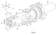
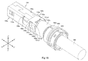
- the Z-Z' direction indicated in Fig. 1A to Fig. 2A and Fig. 2C to Fig. 2D is the direction in which first and second shells 700a, 700b (to be described) of the shield case 700 are combined together.
- the Z-Z' direction corresponds to the "first direction,” the Z direction to the "one side of the first direction,” and the Z' direction to the "other side of the first direction” in the claims.
- the Y-Y' direction indicated in Fig. 1A to Fig. 2C is the lengthwise direction of the first and second shells 700a, 700b of the shield case 700 and also the direction in which the plug P is connected to a receptacle connector (not shown, hereinafter referred to as a "receptacle").
- the Y-Y' direction is orthogonal to the Z-Z' direction.
- the Y-Y' direction corresponds to the "second direction,” the Y' direction to the "one side of the second direction,” and the Y direction to the "other side of the second direction” in the claims.
- the X-X' direction indicated in Fig. 1A to Fig. 1B , Fig. 2B and Fig. 2D is the width direction of the first and second shells 700a, 700b of the shield case 700.
- the X-X' direction is orthogonal to the Z-Z' direction and the Y-Y' direction (crosses the Z-Z' direction and the Y-Y' direction at right angles).
- the X-X' direction corresponds to the "third direction,” the X direction to the "one side of the third direction,” and the X' direction to the "other side of the third direction” in the claims.
- the housing 200 is made of an insulating resin.
- the housing 200 includes a middle portion 210, a distal portion 220, a basal portion 230, a plurality of receiving holes 240a, and a plurality of receiving holes 240b.
- the middle portion 210 is a block of rectangular cuboid shape.
- the distal portion 220 is a block of rectangular cuboid shape, extending in the Y direction from the Y-direction end face of the middle portion 210.
- the distal portion 220 is smaller in the Z-Z' direction and in the X-X' direction than the middle portion 210.
- the distal portion 220 serves as the connecting part of the plug P to fit in a connecting hole of the receptacle.
- the receiving holes 240a are spaced from each other in the X-X' direction and extend in the Y-Y' direction in the Z-direction portion of the middle portion 210 and the distal portion 220.
- the receiving holes 240b are spaced from each other in the X-X' direction and extend in the Y-Y' direction in the Z' direction portion of the middle portion 210 and the distal portion 220. As best illustrated in Fig. 2A , the receiving holes 240a, 240b extend in the Y-Y' direction through the middle portion 210 and the distal portion 220.
- the basal portion 230 is a rectangular plate extending in the Y' direction from the Y'-direction face of the middle portion 210.
- the basal portion 230 is smaller in the Z-Z' direction than the middle portion 210 and also smaller than the distal portion 220 and is as large in the X-X' direction as the middle portion 210.
- the basal portion 230 includes a pair of connecting grooves 231a, a pair of connecting grooves 231b, a pair of press-fit holes 232a, and a pair of press-fit holes 232b.
- the connecting grooves 231a are provided in the Z-direction face of the basal portion 230 and are spaced from each other in the X-X' direction.
- the connecting grooves 231 a extend in the Y-Y' direction, open at its Z-direction and Y'-direction sides, and communicate with the respective receiving holes 240a.
- the connecting grooves 231b are provided in the Z'-direction face of the basal portion 230 and are spaced from each other in the X-X' direction.
- the connecting grooves 231b extend in the Y-Y' direction, open at its Z'-direction and Y'-direction sides, and communicate with the respective receiving holes 240b.
- the press-fit holes 232a are provided on the Z' direction side relative to the connecting grooves 231a of the basal portion 230.
- the press-fit holes 232a extend in the Y-Y' direction and open at its Y'-direction side.
- the press-fit holes 232a communicate with the respective receiving holes 240a and the respective connecting grooves 231a.
- the press-fit hole 232a is larger in the X-X' direction than the connecting groove 231a.
- the press-fit holes 232b are provided on the Z-direction side relative to the connecting grooves 231b of the basal portion 230.
- the press-fit holes 232b extend in the Y-Y' direction and open at its Y'-direction side.
- the press-fit holes 232b communicate with the respective receiving holes 240b and the respective connecting grooves 231b.
- the press-fit hole 232b is larger in the X-X' direction than the connecting groove 231b.
- each terminal 100 is formed of a metal plate.
- Each terminal 100 includes a middle portion 110, a pair of contact portions 120, and a connecting portion 130.
- the middle portion 110 is a plate curved to form a circular tube.
- the contact portions 120 are plates of half-tube shape extending in the Y direction from the respective Y-direction end faces of the middle portions 110 and being opposed to each other in the X-X' direction.
- the connecting portion 130 is a generally rectangular flat plate extending in the Y' direction from the Y'-direction end face of the middle portion 110.
- the connecting portion 130 is slightly larger in the X-X' direction than any press-fit hole 232a or 232b of the housing 200.
- the middle portions 110 and the contact portions 120 are received in the respective receiving holes 240a of the housing 200, and the connecting portions 130 are press-fitted in the respective press-fit holes 232a of the housing 200.
- the middle portions 110 and the contact portions 120 are received in the respective receiving holes 240b of the housing 200, and the connecting portions 130 of the terminals are press-fitted in the respective press-fit holes 232b of the housing 200.
- the two terminals 100 and the other two terminals 100 are symmetrically arranged in the Z-Z' direction.
- pins of the receptacle are inserted through the receiving holes 240a, 240b and then inserted between the contact portions 120 of the terminals 100. This brings the contact portions 120 respectively into elastic contact with the pins of the receptacle. This establishes connection between the plug P and the receptacle.
- the cable 300 includes a plurality of signal wires 310 (signal transmission part), an optional shield conductor (not shown), and an outer insulator 320.
- the signal wires 310 each include a core wire 311 and an inner insulator 312.
- the inner insulator 312 is a tuboid insulator covering the core wire 311.
- the shield conductor when present, is a tuboid conductor surrounding all the signal wires 310.
- the outer insulator 320 is a tuboid insulator covering the shield conductor if present, and covering the signal wires 310 if no shield conductor is present.
- the outer insulator 320 and the shield conductor are cut off at their Y-direction end portions to allow the signal wires 310 to protrude in the Y direction from the outer insulator 320 and the shield conductor. These protruding portions will be hereinafter referred to as protruding portions of the signal wires 310.
- the Y-direction end portions of the inner insulators 312 are cut off to allow the core wires 311 to protrude in the Y direction.
- These protruding portions will be hereinafter referred to as protruding portions of the core wires 311.
- the protruding portions of the core wires 311 are received in the respective connecting grooves 231a of the housing 200 and soldered to the respective connecting portions 130 of the two terminals 100 on the Z-direction side (see Fig. 2A ).
- the protruding portions of the core wires 311 are received in the respective connecting grooves 231b of the housing 200 and soldered to the respective connecting portions 130 of the two terminals 100 on the Z'-direction side (see Fig. 2A ).
- details of the sectional view of the cable 300 are not depicted in Fig. 2A to Fig. 2D .
- the molded member 400 is an insulating resin molded article and fixed to the basal portion 230 of the housing 200.
- the basal portion 230 of the housing 200, the connecting portions 130 of the terminals 100, and the protruding portions of the signal wires 310 of the cable 300 are embedded in the molded member 400.
- the molded member 400 is in intimate contact with the basal portion 230 of the housing 200, the connecting portions 130 of the terminals 100, and the protruding portions of the signal wires 310 of the cable 300.
- the gasket 500 is a ring-shaped elastic body made of silicone rubber or the like material.
- the gasket 500 has an inner diameter that is slightly smaller than the outer diameter of the outer insulator 320 of the cable 300.
- the cable 300 is received through the gasket 500, so that the gasket 500 is in intimate contact with the outer insulator 320 of the cable 300.
- the gasket 500 is provided with a ring-shaped fitting recess 510 along its outer peripheral face.
- the spacer 600 is a circular tube made of an insulating resin.
- the spacer 600 has an inner diameter that is larger than the outer diameter of the outer insulator 320 of the cable 300.
- the cable 300 is received through the spacer 600.
- the spacer 600 is located on the Y' direction side relative to the gasket 500.
- a plurality of engaging projections 610 are provided at intervals circumferentially along the outer peripheral face of the spacer 600.
- the outer peripheral face of the spacer 600 is also provided with a guide protrusion 620 in an area thereof between two adjacent engaging projections 610.
- the shield case 700 includes a first shell 700a, a second shell 700b, a first retainer 700c, a second retainer 700d, a third retainer 700e, and a coupling portion 700f.
- the first shell 700a, the second retainer 700d, the third retainer 700e, and the coupling portion 700f are formed of a single metal plate.
- the second shell 700b and the first retainer 700c are formed of a single metal plate.
- the first shell 700a includes a tube 710a, a half tube 720a, a pair of engaging holes 730a (first engaging hole), a pair of engaging projections 740a, a pair of legs 750a, and a coupling portion 760a.
- the half tube 720a is a half of a rectangular tube, extending in the Y-Y' direction and opening at its Z'-direction side.
- the half tube 720a includes a Z-direction-side plate, an X-direction-side lateral plate, an X'-direction-side lateral plate, and a Y'-direction end face 721 a.
- the X-direction-side lateral plate extends in the Z' direction from the X-direction end of the Z-direction-side plate.
- the X'-direction-side lateral plate extends in the Z' direction from the X'-direction end of the Z-direction-side plate.
- the distance in the X-X' direction between the inner faces of these lateral plates is substantially equal to the X-X' direction dimension of the molded member 400.
- the half tube 720a fits over the portion of the molded member 400 other than the portion fixed to the basal portion 230 (see Fig. 2A to Fig. 2C ).
- the Z-direction-side plate, the X-direction-side lateral plate, and the X'-direction-side lateral plate of the half tube 720a have respective Y'-direction end faces, which constitute the Y'-direction end face 721 a of the half tube 720a.
- the end face 721a includes a first part 721a1, a second part 721a2, and a third part 721a3.
- the first part 721a1 is the Z-direction-side part of the end face 721a, i.e. the Y'-direction end of the Z-direction-side plate.
- the second part 721a2 is the X-direction-side part of the end face 721a, i.e.
- the third part 721a3 is the X'-direction-side part of the end face 721a, i.e. the Y'-direction end of the X'-direction-side lateral plate.
- the tube 710a is a rectangular tube extending from the half tube 720a in the Y direction.
- the tube 710a has an inner shape corresponds to the outer shape of the middle portion 210 of the housing 200.
- the tube 710a houses the distal portion 220 of the housing 200 with a clearance therebetween.
- the tube 710a also fits over the middle portion 210 of the housing 200, the basal portion 230 of the housing 200, and the portion of the molded member 400 fixed to the basal portion 230 (see Fig. 2A to Fig. 2C ).
- the tube 710a includes a Z-direction-side top plate, a Z'-direction-side bottom plate, an X-direction-side lateral plate, and an X'-direction-side lateral plate.
- the X-direction-side lateral plate joins the X-direction end of the top plate to the X-direction end of the bottom plate.
- the X'-direction-side lateral plate joins the X'-direction end of the top plate to the X'-direction end of the bottom plate.
- the engaging holes 730a are slits, one of which extends in the X-direction end portion of the bottom plate and the Z'-direction-side portion of the X-direction-side lateral plate of the tube 710a.
- the other slit extends in the X'-direction end portion of the bottom plate and the Z'-direction-side portion of the X'-direction-side lateral plate of the tube 710a.
- the engaging holes 730a are opposed to each other in the X-X' direction.
- the engaging projections 740a are plate-like portions of the lateral plates of the half tube 720a that are cut and bend outward.
- the engaging projections 740a are opposed to each other in the X-X' direction.
- the legs 750a are projections protruding from the Z'-direction ends of the lateral plates of the half tube 720a.
- the coupling portion 760a is centrally provided on the Y'-direction end of the Z-direction-side plate of the half tube 720a.
- the coupling portion 760a is a plate extending in the Y-Y' direction.
- the second retainer 700d is a plate contiguous with the coupling portion 760a of the first shell 700a and is located on the Y' direction side relative to the end face 721 a of the half tube 720a.
- the second retainer 700d curves in a circular tube shape along the outer periphery of the cable 300 to form a circular tube.
- the second retainer 700d retains the cable 300 so as to be in contact with the shield conductor (see Fig. 2A to Fig. 2D ). In other words, the cable 300 is received in and retained by the second retainer 700d.
- the third retainer 700e is a plate joined to the second retainer 700d by the coupling portion 700f so as to be on the Y' direction side relative to the second retainer 700d.
- the third retainer 700e curves in a circular tube shape along the ring-shaped bottom of the fitting recess 510 of the gasket 500 to form a circular tube.
- the third retainer 700e fits in the fitting recess 510 of the gasket 500 so as to retain the gasket 500 (see Fig. 2A to Fig. 2C ).
- the coupling portion 700f is a plate that joins the top portion of the second retainer 700d to the top portion of the third retainer 700e.
- the second shell 700b is a half tube to be combined with the half tube 720a of the first shell 700a in the Z-Z' direction.
- the second shell 700b includes a shell body 710b, a coupling portion 720b, a pair of engaging holes 730b (second engaging hole), a pair of engaging holes 740b, and a pair of engaging arms 750b.
- the shell body 710b is a half tube or channel section.
- the shell body 710b includes a Z'-direction-side plate, an X-direction-side lateral plate, and an X'-direction-side lateral plate.
- the X-direction-side lateral plate extends in the Z direction from the X-direction end of the Z'-direction-side plate.
- the X'-direction-side lateral plate extends in the Z direction from the X'-direction end of the Z'-direction-side plate.
- the distance in the X-X' direction between the inner faces of these lateral side plates is substantially equal to the X-X' direction distance between the outer faces of the lateral plates of the half tube 720a of the first shell 700a.
- the lateral plates of the shell body 710b are in contact with the outer faces of the lateral plates of the half tube 720a, and the Z'-direction-side plate of the shell body 710b closes the opening on Z'-direction side of the half tube 720a, so that the shell body 710b is combined with the half tube 720a of the first shell 700a in the Z-Z' direction.
- the first and second shells 700a, 700b as combined constitute a tube to cover the terminals 100, the housing 200, the protruding portions of the signal wires 310 of the cable 300, and the molded member 400.
- the axial direction of the tube is the Y-Y' direction. In the illustrated embodiment the tube is of square cross-section when seen in the Y' direction, but may be of any suitable polygonal or curved shape.
- the engaging holes 730b are through holes respectively made in the lateral plates of the shell body 710b and opposed to each other in the X-X' direction.
- the engaging holes 730b are of shapes corresponding to the respective outer shapes of the engaging projections 740a of the first shell 700a.
- the engaging projections 740a engage with the respective engaging holes 730b from the inside of the shell body 710b.
- the engaging holes 740b are through holes in the lateral plates of the shell body 710b, on the Z'-direction side relative to the engaging holes 730b.
- the engaging holes 740b generally extend in the Z-Z' direction and extends a little further to the X- and X'- direction end portions of the Z'-direction-side plate of the shell body 710b.
- the engaging holes 740b each has a Y-Y' direction dimension substantially equal to or slightly larger than the Y-Y' direction dimension of each leg 750a of the first shell 700a.
- the legs 750a engage in the respective engaging
- the engaging arms 750b are plates extending in the Y direction from the respective lateral plates of the shell body 710b so as to be opposed to each other in the X-X' direction.
- the engaging arms 750b are bent inwards at their free ends on the Y-direction-side. The free ends of the engaging arms 750b engage in the respective engaging holes 730a of the first shell 700a from the outside of the first shell 700a.
- the coupling portion 720b is centrally provided on the Y'-direction end of the Z'-direction-side plate of the shell body 710b.
- the coupling portion 720b is a plate extending in the Y-Y' direction.
- the first retainer 700c is a plate contiguous with the coupling portion 720b of the second shell 700b and located on the Y' direction side relative to the end face 721 a of the first shell 700a.
- the first retainer 700c curves in a circular tube shape along the outer face of the second retainer 700d to form a circular tube.
- the first retainer 700c retains the second retainer 700d, i.e. retains the cable 300 over the second retainer 700d.
- the first retainer 700c has an inner diameter such as to allow the first retainer 700c to contact with the first part 721a1, the second part 721a2, and the third part 721a3 of the end face 721 a of the first shell 700a.
- the first retainer 700c is in contact with the first part 721a1, the second part 721 a2, and the third part 721 a3 of the end face 721a of the first shell 700a.
- the first retainer 700c by way of the contact with the second retainer 700d, is electrically connected to the shield conductor of the cable 300.
- the case is made of an insulating resin.
- the case has a housing hole to house the terminals 100, the housing 200, the Y-direction end portion of the cable 300, the molded member 400, the gasket 500, the spacer 600, and the shield case 700.
- An inner wall of the housing hole of the case has a guide recess corresponding to the guide protrusion 620 of the spacer 600.
- the guide recess extends in the Y-Y' direction.
- the inner wall of the housing hole also has engaging recesses at positions corresponding to the engaging projections 610 of the spacer 600. The engaging recesses engage with the engaging projections 610 so as to fix the spacer 600 to the case.
- the plug P configured as described above may be assembled in the following steps. First, the terminals 100 and the housing 200 are prepared. The contact portions 120 and the middle portions 110 of the terminals 100 are inserted into the receiving holes 240a, 240b of the housing 200 from the Y'-direction side. Then, the contact portions 120 and the middle portions 110 of the terminals 100 are housed in the receiving holes 240a, 240b, and the connecting portions 130 are press-fitted into the connecting grooves 231a, 231b of the housing 200. The terminals 100 are thus held in the housing 200.
- the cable 300 and the spacer 600 are also prepared.
- the Y-direction end portion of the cable 300 is inserted through the spacer 600.
- the gasket 500 is prepared, and the Y-direction end of the cable 300 is inserted through the gasket 500.
- the gasket 500 now fittingly engages over the cable 300 and is located on the Y-direction side relative to the spacer 600.
- the protruding portions of the core wires 311 of the signal wires 310 of the cable 300 are inserted into the respective connecting grooves 231a, 231b of the housing 200 and brought into contact with the connecting portions 130 of the terminals 100. Then, the protruding portions of the core wires 311 are soldered to the respective connecting portions 130.
- the basal portion 230 of the housing 200 and the protruding portions of the signal wires 310 of the cable 300 are placed into a mold (not shown). Resin material is injected into the mold, and the hardened resin becomes the molded member 400. The basal portion 230 and the protruding portions of the signal wires 310 of the cable 300 are thus insert molded in the molded member 400, and the molded member 400 is fixed to the basal portion 230.
- first shell 700a Also prepared are the first shell 700a, the second retainer 700d, the third retainer 700e, and the coupling portion 700f by stamping a single metal plate.
- the second retainer 700d and the third retainer 700e are planar and not shaped in a circular tube.
- the housing 200 and the molded member 400 are inserted into the first shell 700a, resulting in the following arrangements 1) to 3):
- the second retainer 700d is curved into a circular tube shape along the outer periphery of the cable 300.
- the second retainer 700d is then crimped so as to retain the cable 300.
- the second retainer 700d is also brought into contact with and electrically connected to the shield conductor of the cable 300 (if present).
- the third retainer 700e is curved into a circular tube shape along the bottom of the fitting recess 510 of the gasket 500.
- the third retainer 700e is then crimped so as to retain the gasket 500.
- the second shell 700b and the first retainer 700c are also prepared by stamping a single metal plate.
- first retainer 700c is planar and not shaped in a circular tube.
- the second shell 700b is combined with the first shell 700a in the Z-Z' direction.
- the second shell 700b is now placed over the half tube 720a of the first shell 700a and closes the opening of the half tube 720a.
- the attachment of the second shell 700b to the first shell 700a results in following arrangements 1) to 3):
- the first retainer 700c is curved into a circular tube shape along the outer circumference of the second retainer 700d.
- the first retainer 700c is then crimped and thereby retains the second retainer 700d.
- the first retainer 700c retains the cable 300 over the second retainer 700d.
- the first retainer 700c is also brought into contact with the first part 721a1, the second part 721 a2, and the third part 721 a3 of the Y'-direction end face 721 a of the first shell 700a.
- the case is also prepared, into the housing hole of which are received the terminals 100, the housing 200, the Y-direction end portion of the cable 300, the molded member 400, the gasket 500, the spacer 600, and the shield case 700.
- the spacer 600 is fixed to the case.
- the plug P is now completely assembled.
- the plug P has at least the following technical features and effects.
- the plug P has an improved durability of for the following reasons.
- a load caused by moving the cable 300 is also shared by the first shell 700a and the first retainer 700c. This is because the first retainer 700c retaining the cable 300 is in contact with the first part 721a1, the second part 721a2, and the third part 721a3 of the Y'-direction end face 721 a of the first shell 700a.
- first retainer 700c retaining the cable 300 is in contact with the second part 721a2 on X-direction side of the end face 721 a of the first shell 700a.
- a load caused by moving the cable 300 is also shared by the first shell 700a and the first retainer 700c. This is because the first retainer 700c retaining the cable 300 is in contact with third part 721a3 on the X'-direction side of the end face 721a of the first shell 700a.
- the engaging arms 750b of the second shell 700b engage with the engaging holes 730a of the first shell 700a from the outside
- the engaging projections 740a of the first shell 700a engage with the engaging holes 730b of the second shell 700b from the inside
- the legs 750a of the first shell 700a engage with the engaging holes 740b of the second shell 700b. Since the first and second shells 700a, 700b are thus fixed to each other, the load caused by moving the cable 300 in any of the cases (1) to (4) described above can be also shared by the first and second shells 700a, 700b. Further, the cable 300 is retained by the second retainer 700d, and the gasket 500 fitting over the cable 300 is retained by the third retainer 700e. Accordingly, the load caused by moving the cable 300 in any of the cases (1) to (4) described above can be also shared by the second retainer 700d and the third retainer 700e.
- the plug P has an improved tensile strength for the following reasons.
- the cable 300 is retained by the first retainer 700c and the second retainer 700d, and the gasket 500 fitting over the cable 300 is retained by the third retainer 700e.
- the first and second shells 700a, 700b are fixed to each other as described above.
- the crimping work of the first retainer 700c can be facilitated.
- the load caused by moving the cable 300 is also shared by the first and second shells 700a, 700b, the first retainer 700c, the second retainer 700d, and the third retainer 700e. Therefore, there is no need to take measures to bear the load, such as increasing the thickness of the first retainer 700c and the coupling portion 720b. Accordingly, the first retainer 700c can be manually crimped. As is obvious, the first retainer 700c may be crimped with a crimping device.
- the cable 300 is unlikely to slide in the Y direction relative to the first and second retainers 700c, 700d.
- the plug connector P was designed such that the first retainer and the Y'-direction end of the first shell are arranged with a gap therebetween, by moving the cable 300 as in one of the cases (1) to (4) described above and reversely moving it, the first retainer would repeatedly move with respect to the first shell in the Y-Y' direction, which may cause the cable held by the first retainer to slide in the Y-Y' direction relative to the first retainer.
- the plug connector P is actually designed such that the first retainer 700c is in contact with the Y'-direction end face 721 a of the first shell 700a as described above. It is therefore possible to prevent the first retainer 700c from moving the Y direction with respect to the first shell 700a, making it unlikely that the cable 300 will slide in the Y direction relative to the first and second retainers 700c, 700d.
- the plug connector of the invention is not limited to the embodiment described above but may be modified in any manner within the scope of the claims. Specific modifications will be described in detail below.
- the cable of the invention may any cable including the signal transmission part.
- the cable may be a cable with at least one core wire, such as a coaxial cable.
- the cable may be an optical fiber cable, which includes at least one optical fiber serving as the signal transmission part.
- the connecting member of the invention may be any member connectable to the cable of any one of the above aspects.
- the connecting member may be a terminal or terminals, a circuit board, or a photoelectric conversion device or devices.
- the terminal(s) may be connected directly to the core wire(s) of the cable of any one of the above aspects.
- the circuit board includes at least one first electrode for connection with the protruding portions of the core wires of the signal wires of the cable.
- the circuit board may include a second electrode or electrodes connectable to a terminal or terminals of the receptacle connector.
- the circuit board may include a terminal or terminals connectable to a terminal or terminals or a pin or pins of a receptacle connector.
- the photoelectric conversion device(s) is mounted on a circuit board and optically coupled to an optical fiber or fibers of an optical fiber cable.
- the photoelectric conversion device converts optical signals transmitted via an optical fiber into electric signals and outputs the signals to a transmission path of the circuit board, and/or converts electric signals transmitted via a transmission path of the board into optical signals and outputs them to an optical fiber.
- the housing of the invention may be omitted.
- the housing of the invention may be any insulating housing adapted to hold at least the connecting member of any one of the above aspects.
- the housing may be a molded resin in which the connecting member of any one of the above aspects is insert-molded.
- the molded member, the gasket, and/or the spacer of the invention may be omitted.
- the gasket of the invention may be any ring-shaped elastic body adapted to receive and make intimate contact with the cable of any one of the above aspects.
- the shield case of the invention may be modified in any manner as long as it includes the first and second shells and the first retainer in the embodiment or of any one of the following aspects.
- the first and second shells of the invention may be modified in any manner as long as they can be combined together in the first direction to form a tube at least partially covering the connecting member and the signal transmission part of any one of the above aspects, and as long as the first shell includes an end face on the one side of the second direction orthogonal to the first direction.
- the first shell of the invention may be a plate extending in the second direction, generally shaped in a flat shape or in a U shape, V shape, or arc shape in sectional view, and including an end face on one side of the second direction.
- the first shell of the invention may alternatively be a half tube (half circular tube or half polygonal tube) extending in the second direction and having an end face on the one side of the second direction.
- the first shell of the invention may alternatively include a half tube (half circular tube or half polygonal tube) and a tube (circular tube or polygonal tube), both of which extend in the second direction and one of which has an end face on the one side of the second direction.
- the half tube and the tube may be different in the dimension in the first direction and/or the dimension in the third direction crossing the first and second directions.
- the end face on the one side of the second direction of any one of the above aspects may have a first part on the one side of the first direction, a second part on one side of the third direction, and a third part on the other side of the third direction.
- the second shell of the invention may be a plate extending in the second direction, generally shaped in a flat shape or in a V shape, or arc shape in sectional view, and adapted to be combined with the first shell in the first direction to close the opening of the half tube of the first shell so that the first and second shells form a tube.
- the second shell of the invention may alternatively be a half tube (half circular tube or half polygonal tube) extending in the second direction.
- the half tube of the second shell may be combined with the above-described plate of the first shell in the first direction to close the opening of the half tube of the second shell so that the first and second shells form a tube.
- the half tube of the second shell may alternatively be combined with the half tube of the first shell in the first direction so that the first and second shells form a tube.
- the first retainer of the invention may be any tube (circular tube or polygonal tube) or half tube (half circular tube or half polygonal tube) for retaining the cable, the first retainer being provided on the second shell of any one of the above aspects so as to be located on the one side of the second direction relative to the end face of the first shell and in contact with at least a part of the end face of the first shell.
- the first retainer may directly retain the cable.
- the first retainer may be in contact with at least one of the first part, the second part, and the third part of the end face on the one side of the second direction of the first shell of any one of the above aspects.
- the shield case of the invention may have no or at least one engaging arm and may have no or at least one first engaging hole.
- the at least one engaging arm if provided, may be any arm extending in the second direction from one of the first and second shells of any one of the above aspects.
- the at least one first engaging hole of the invention if provided, may be any hole in the other one of the first and second shells for engaging the associated engaging arm(s).
- the engaging arm(s) of any one of the above aspects may engage with the first engaging hole(s) of any one of the above aspects from the outside or inside of the other shell.
- the shield case of the invention may have no or at least one second engaging hole and may have no or at least one engaging projection.
- the at least one second engaging hole if provided, may be any hole in one of the first and second shells of any one of the above aspects.
- the at least one engaging projection if provided, may be any projection on the other one of the first and second shells of any one of the above aspects and can engage with the associated second engaging hole(s).
- the engaging projection(s) of any one of the above aspects may engage with the second engaging hole(s) of any one of the above aspects from the inside or outside of the one shell.
- the third engaging hole and/or the leg of the shield case of the invention may be omitted.
- the second retainer of the shield case of the invention may be omitted.
- the second retainer may be any tube (circular tube or polygonal tube) or half tube (half circular tube or half polygonal tube) for retaining the cable, the second retainer being provided on the half tube of the first shell of any one of the above aspects so as to be located on the one side of the second direction relative to the end face of the first shell.
- the second retainer may be located on the one side of the second direction relative to the first retainer so as to allow both the first and second retainers to directly retain the cable.
- the second retainer may retain the first retainer that directly retains the cable.
- the third retainer of the shield case of the invention may be omitted.
- the third retainer may be any tube (circular tube or polygonal tube) or half tube (half circular tube or half polygonal tube) for retaining the gasket of any one of the above aspects.
- the third retainer further has one of the following configurations: (1) The third retainer may be coupled to the first shell of any one of the above aspects and located on the one side of the second direction relative to the end face on the one side of the second direction of the first shell. In this case, the second retainer can be omitted. (2) Alternatively, the third retainer may be coupled to the second retainer and located on the one side of the second direction relative to the second retainer.
- the plug connectors in the embodiments and variants thereof are described above by way of examples only.
- the materials, shapes, dimensions, numbers, arrangements, and other configurations of the constituents of the plug connectors may be modified in any manner if they can perform similar functions.
- the configurations of the embodiments and the variants described above may be combined in any possible manner.
- the first direction of the invention may be any direction in which to combine the first and second shells of any one of the above aspects.
- the second direction of the invention may be any direction orthogonal to the first direction.
- the third direction of the invention may be any direction crossing the first direction and the second direction.
Landscapes
- Details Of Connecting Devices For Male And Female Coupling (AREA)
Abstract
Description
- The invention relates to plug connectors.
- A conventional plug connector is disclosed in Japanese Unexamined Patent Publication No.
09-199230 - In the state where the above conventional plug connector is connected to a receptacle connector, the cable may be moved in a direction including a component of the connecting direction of the plug connector. The cable moved in this manner applies a load only on the area where the retainer retaining the cable is connected to the first shell. As a result, the conventional plug connector has a low durability.
- In the above circumstances, the invention provides a plug connector with an improved durability.
- To solve the above problem, a plug connector of the invention includes a connecting member, a cable, and a shield case. The cable includes a signal transmission part connected to the connecting member. The shield case includes first and second shells and a first retainer. The first and second shells are combined together in a first direction so as to form a tube at least partially covering the connecting member and the signal transmission part. The first shell has an end face on one side of a second direction. The second direction is orthogonal to the first direction. The first retainer is a tube or half tube for retaining the cable. The first retainer is provided on the second shell so as to be located on the one side of the second direction relative to the end face of the first shell and in contact with at least a part of the end face of the first shell.
- The plug connector of this aspect has an improved durability for the following reasons. When the cable is moved (pried) in a direction including a component of the other side of the second direction in a state where the plug connector is connected to the receptacle connector in the second direction (hereinafter referred to as a "connected state"), the first retainer is in contact with at least a part of the end face of the first shell. Accordingly, a load caused by moving the cable is also shared by the first shell.
- The first shell may include a half tube extending in the second direction. The half tube of the first shell may include the end face, which may include a first part on one side of the first direction, a second part on one side of a third direction, and a third part on the other side of the third direction. The third direction may be orthogonal to the first direction and the second direction. The second shell may be a half tube or plate to be combined with the half tube of the first shell. The first retainer may be in contact with at least one of the first part, the second part, or the third part.
- The plug connector of this aspect has an improved durability as detailed below. In a case (1) where the cable in the connected state is moved (pried) in a direction including components of the other side of the second direction and one side of the first direction, the first retainer is in contact with the first part of the end face of the first shell. Therefore, a load caused by moving the cable is also shared by the first retainer and the first shell. In a case (2) where the cable in the connected state is moved (pried) in a direction including components of the other side of the second direction and one side of the third direction in the connected state, the first retainer is in contact with the second part of the end face of the first shell. Therefore, a load caused by moving the cable is also shared by the first retainer and the first shell. In a case (3) where the cable in the connected state is moved (pried) in a direction including components of the other side of the second direction and the other side of the third direction, the first retainer is in contact with the third part of the end face of the first shell. Therefore, a load caused by moving the cable is also shared by the first retainer and the first shell.
- The shield case may further include an engaging arm extending in the second direction from one of the first and second shells and a first engaging hole in the other one of the first and second shells. The first engaging hole may be configured to engage the engaging arm.
- The plug connector of this aspect has a further improved durability and an improved tensile strength. This is because the engaging arm engages with the first engaging hole.
- The engaging arm may be provided as a pair of engaging arms extending from one of the first and second shells so as to be opposed to each other in the third direction. The first engaging hole may be provided as a pair of first engaging holes in the other one of the first and second shells. The first engaging holes may be opposed to each other in the third direction. The engaging arms may be configured to engage in the respective first engaging holes from outside of the other shell.
- The plug connector of this aspect includes further improved durability and tensile strength. This is because the pair of engaging arms engages with the pair of first engaging holes.
- The shield case may further include a second engaging hole in one of the first and second shells and an engaging projection on the other one of the first and second shells. The engaging projection may be configured to engage in the second engaging hole.
- The plug connector of this aspect includes further improved durability and tensile strength. This is because the engaging projection engages with the second engaging hole.
- The second engaging holes may be provided as a pair of second engaging holes in one of the first and second shells. The second engaging holes may be opposed to each other in the third direction. The engaging projection may be provided as a pair of engaging projections on the other one of the first and second shells. The engaging projections may be opposed to each other in the third direction and configured to engage in the respective second engaging holes from the inside of the one shell.
- The plug connector of this aspect includes further improved durability and tensile strength. This is because the pair of engaging projections engages with the pair of second engaging holes.
- The shield case may further include a second retainer being a tube or half tube for retaining the cable. The second retainer may be provided in the first shell so as to be located on the one side of the second direction relative to the end face of the first shell.
- The plug connector of this aspect has further improved durability and tensile strength. This is because the cable is retained by the second retainer as well as the first retainer retains the cable.
- The first retainer may retain the cable over the second retainer.
- The plug connector of this aspect includes further improved durability and tensile strength. This is because the second retainer retains the cable and the first retainer also retains the cable over the second retainer.
- The plug connector of any one of the above aspects may further include a gasket of ring shape. The cable may be inserted through and in intimate contact with the gasket. The shield case may further include a third retainer being a tube or half tube for retaining the gasket. The third retainer may be coupled to the first shell so as to be located on the one side of the second direction relative to the end face of the first shell.
- The plug connector of this aspect has further improved durability and tensile strength. This is because the third retainer retains the gasket in intimate contact with the cable.
- The third retainer may be located on the one side of the second direction relative to the second retainer, not relative to the first shell.
- The plug connector of this aspect has further improved durability and tensile strength. This is because not only the cable is retained by the first and the second retainer, but also the gasket in intimate contact with the cable is retained by the third retainer.
- The connector of any one of the above aspects may further include a housing having an insulating property and holding the connecting member. The first and second shells may at least partially cover the connecting member, the housing, and the signal transmission part.
-
-
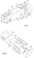
Fig. 1A is a front, top, left side perspective view of a connector in an embodiment of the invention, with a case omitted; -
Fig. 1B is a back, bottom, right side perspective view of the connector with the case omitted; -
Fig. 2A is a sectional view of the connector taken along 2A-2A inFig. 1A , with the internal structure of the cable omitted; -
Fig. 2B is a sectional view of the connector taken along 2B-2B inFig. 1A , with the internal structure of the cable being omitted; -
Fig. 2C is a sectional view of the connector taken along 2C-2C inFig. 1A , with the internal structure of the cable being omitted; -
Fig. 2D is a sectional view of the connector taken along 2D-2D inFig. 1A , with the internal structure of the cable being omitted; -
Fig. 3 is a front, top, left side perspective view of a housing, a molded member, a cable, a gasket, and a spacer of the connector, with the molded member illustrated as an see-through element; -
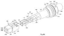
Fig. 4A is an exploded perspective view of the housing, terminals, and the cable of the connector as viewed from front, top, and left side; -
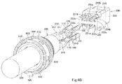
Fig. 4B is an exploded perspective view of the housing, the terminals, and the cable of the connector as viewed from back, bottom, and left side; -
Fig. 5A is a front, top, left side perspective view of a first shell, a second retainer, a third retainer, and a coupling portion of a shield case of the connector; -
Fig. 5B is a back, bottom, right side perspective view of the first shell, the second retainer, the third retainer, and the coupling portion of the shield case of the connector; -
Fig. 6A is a front, top, left side perspective view of a second shell and a first retainer of the shield case of the connector; and -
Fig. 6B is a back, bottom, right side perspective view of the second shell and the first retainer of the shield case of the connector. - In the brief description of the drawings above and the description of embodiments which follows, relative spatial terms such as "upper", "lower", "top", "bottom", "left", "right", "front", "rear", etc., are used for the convenience of the skilled reader and refer to the orientation of the plug connector and its constituent parts as depicted in the drawings. No limitation is intended by use of these terms, either in use of the invention, during its manufacture, shipment, custody, or sale, or during assembly of its constituent parts or when incorporated into or combined with other apparatus.
- A plug connector (hereinafter referred to as a plug P) in an embodiment of the invention will be described with reference to
Fig. 1A to Fig. 6B . The plug P includes a plurality of terminals 100 (connecting member), ahousing 200, acable 300, a moldedmember 400, agasket 500, aspacer 600, ashield case 700, and a case (not shown). These constituents of the plug P will be described below in detail. The Z-Z' direction indicated inFig. 1A to Fig. 2A andFig. 2C to Fig. 2D is the direction in which first andsecond shells shield case 700 are combined together. The Z-Z' direction corresponds to the "first direction," the Z direction to the "one side of the first direction," and the Z' direction to the "other side of the first direction" in the claims. The Y-Y' direction indicated inFig. 1A to Fig. 2C is the lengthwise direction of the first andsecond shells shield case 700 and also the direction in which the plug P is connected to a receptacle connector (not shown, hereinafter referred to as a "receptacle"). The Y-Y' direction is orthogonal to the Z-Z' direction. The Y-Y' direction corresponds to the "second direction," the Y' direction to the "one side of the second direction," and the Y direction to the "other side of the second direction" in the claims. The X-X' direction indicated inFig. 1A to Fig. 1B ,Fig. 2B andFig. 2D is the width direction of the first andsecond shells shield case 700. The X-X' direction is orthogonal to the Z-Z' direction and the Y-Y' direction (crosses the Z-Z' direction and the Y-Y' direction at right angles). The X-X' direction corresponds to the "third direction," the X direction to the "one side of the third direction," and the X' direction to the "other side of the third direction" in the claims. - As best illustrated in
Fig. 3 to Fig. 4B , thehousing 200 is made of an insulating resin. Thehousing 200 includes amiddle portion 210, adistal portion 220, abasal portion 230, a plurality of receivingholes 240a, and a plurality of receivingholes 240b. - The
middle portion 210 is a block of rectangular cuboid shape. Thedistal portion 220 is a block of rectangular cuboid shape, extending in the Y direction from the Y-direction end face of themiddle portion 210. Thedistal portion 220 is smaller in the Z-Z' direction and in the X-X' direction than themiddle portion 210. Thedistal portion 220 serves as the connecting part of the plug P to fit in a connecting hole of the receptacle. The receivingholes 240a are spaced from each other in the X-X' direction and extend in the Y-Y' direction in the Z-direction portion of themiddle portion 210 and thedistal portion 220. The receivingholes 240b are spaced from each other in the X-X' direction and extend in the Y-Y' direction in the Z' direction portion of themiddle portion 210 and thedistal portion 220. As best illustrated inFig. 2A , the receivingholes middle portion 210 and thedistal portion 220. - As illustrated in
Fig. 3 to Fig. 4B , thebasal portion 230 is a rectangular plate extending in the Y' direction from the Y'-direction face of themiddle portion 210. Thebasal portion 230 is smaller in the Z-Z' direction than themiddle portion 210 and also smaller than thedistal portion 220 and is as large in the X-X' direction as themiddle portion 210. Thebasal portion 230 includes a pair of connectinggrooves 231a, a pair of connectinggrooves 231b, a pair of press-fit holes 232a, and a pair of press-fit holes 232b. - As best illustrated in
Fig. 4B , the connectinggrooves 231a are provided in the Z-direction face of thebasal portion 230 and are spaced from each other in the X-X' direction. The connectinggrooves 231 a extend in the Y-Y' direction, open at its Z-direction and Y'-direction sides, and communicate with the respective receivingholes 240a. The connectinggrooves 231b are provided in the Z'-direction face of thebasal portion 230 and are spaced from each other in the X-X' direction. The connectinggrooves 231b extend in the Y-Y' direction, open at its Z'-direction and Y'-direction sides, and communicate with the respective receivingholes 240b. - The press-
fit holes 232a are provided on the Z' direction side relative to the connectinggrooves 231a of thebasal portion 230. The press-fit holes 232a extend in the Y-Y' direction and open at its Y'-direction side. The press-fit holes 232a communicate with the respective receivingholes 240a and the respective connectinggrooves 231a. The press-fit hole 232a is larger in the X-X' direction than the connectinggroove 231a. The press-fit holes 232b are provided on the Z-direction side relative to the connectinggrooves 231b of thebasal portion 230. The press-fit holes 232b extend in the Y-Y' direction and open at its Y'-direction side. The press-fit holes 232b communicate with the respective receivingholes 240b and the respective connectinggrooves 231b. The press-fit hole 232b is larger in the X-X' direction than the connectinggroove 231b. - As best illustrated in
Fig. 4A to Fig. 4B , each terminal 100 is formed of a metal plate. Each terminal 100 includes amiddle portion 110, a pair ofcontact portions 120, and a connectingportion 130. Themiddle portion 110 is a plate curved to form a circular tube. Thecontact portions 120 are plates of half-tube shape extending in the Y direction from the respective Y-direction end faces of themiddle portions 110 and being opposed to each other in the X-X' direction. The connectingportion 130 is a generally rectangular flat plate extending in the Y' direction from the Y'-direction end face of themiddle portion 110. The connectingportion 130 is slightly larger in the X-X' direction than any press-fit hole housing 200. - With regard to two of the four
terminals 100, themiddle portions 110 and thecontact portions 120 are received in the respective receivingholes 240a of thehousing 200, and the connectingportions 130 are press-fitted in the respective press-fit holes 232a of thehousing 200. With regard to the other twoterminals 100, themiddle portions 110 and thecontact portions 120 are received in the respective receivingholes 240b of thehousing 200, and the connectingportions 130 of the terminals are press-fitted in the respective press-fit holes 232b of thehousing 200. The twoterminals 100 and the other twoterminals 100 are symmetrically arranged in the Z-Z' direction. - In use, when the
distal portion 220 of thehousing 200 is connected into the connecting hole of the receptacle, pins of the receptacle are inserted through the receivingholes contact portions 120 of theterminals 100. This brings thecontact portions 120 respectively into elastic contact with the pins of the receptacle. This establishes connection between the plug P and the receptacle. - As best illustrated in
Fig. 4A andFig. 4B , thecable 300 includes a plurality of signal wires 310 (signal transmission part), an optional shield conductor (not shown), and anouter insulator 320. Thesignal wires 310 each include acore wire 311 and aninner insulator 312. Theinner insulator 312 is a tuboid insulator covering thecore wire 311. The shield conductor, when present, is a tuboid conductor surrounding all thesignal wires 310. Theouter insulator 320 is a tuboid insulator covering the shield conductor if present, and covering thesignal wires 310 if no shield conductor is present. Theouter insulator 320 and the shield conductor are cut off at their Y-direction end portions to allow thesignal wires 310 to protrude in the Y direction from theouter insulator 320 and the shield conductor. These protruding portions will be hereinafter referred to as protruding portions of thesignal wires 310. In the protruding portions of thesignal wires 310, the Y-direction end portions of theinner insulators 312 are cut off to allow thecore wires 311 to protrude in the Y direction. These protruding portions will be hereinafter referred to as protruding portions of thecore wires 311. With regard to two of thesignal wires 310, the protruding portions of thecore wires 311 are received in the respective connectinggrooves 231a of thehousing 200 and soldered to the respective connectingportions 130 of the twoterminals 100 on the Z-direction side (seeFig. 2A ). With regard to the other twosignal wires 310, the protruding portions of thecore wires 311 are received in the respective connectinggrooves 231b of thehousing 200 and soldered to the respective connectingportions 130 of the twoterminals 100 on the Z'-direction side (seeFig. 2A ). For convenience of illustration, details of the sectional view of thecable 300 are not depicted inFig. 2A to Fig. 2D . - The molded
member 400 is an insulating resin molded article and fixed to thebasal portion 230 of thehousing 200. Thebasal portion 230 of thehousing 200, the connectingportions 130 of theterminals 100, and the protruding portions of thesignal wires 310 of thecable 300 are embedded in the moldedmember 400. In other words, the moldedmember 400 is in intimate contact with thebasal portion 230 of thehousing 200, the connectingportions 130 of theterminals 100, and the protruding portions of thesignal wires 310 of thecable 300. - The
gasket 500 is a ring-shaped elastic body made of silicone rubber or the like material. Thegasket 500 has an inner diameter that is slightly smaller than the outer diameter of theouter insulator 320 of thecable 300. Thecable 300 is received through thegasket 500, so that thegasket 500 is in intimate contact with theouter insulator 320 of thecable 300. Thegasket 500 is provided with a ring-shapedfitting recess 510 along its outer peripheral face. - The
spacer 600 is a circular tube made of an insulating resin. Thespacer 600 has an inner diameter that is larger than the outer diameter of theouter insulator 320 of thecable 300. Thecable 300 is received through thespacer 600. Thespacer 600 is located on the Y' direction side relative to thegasket 500. A plurality of engagingprojections 610 are provided at intervals circumferentially along the outer peripheral face of thespacer 600. The outer peripheral face of thespacer 600 is also provided with aguide protrusion 620 in an area thereof between two adjacentengaging projections 610. - The
shield case 700 includes afirst shell 700a, asecond shell 700b, afirst retainer 700c, asecond retainer 700d, athird retainer 700e, and acoupling portion 700f. Thefirst shell 700a, thesecond retainer 700d, thethird retainer 700e, and thecoupling portion 700f are formed of a single metal plate. Thesecond shell 700b and thefirst retainer 700c are formed of a single metal plate. - As best illustrated in
Fig. 5A and Fig. 5B , thefirst shell 700a includes atube 710a, ahalf tube 720a, a pair of engagingholes 730a (first engaging hole), a pair of engagingprojections 740a, a pair oflegs 750a, and acoupling portion 760a. - The
half tube 720a is a half of a rectangular tube, extending in the Y-Y' direction and opening at its Z'-direction side. Thehalf tube 720a includes a Z-direction-side plate, an X-direction-side lateral plate, an X'-direction-side lateral plate, and a Y'-direction end face 721 a. The X-direction-side lateral plate extends in the Z' direction from the X-direction end of the Z-direction-side plate. The X'-direction-side lateral plate extends in the Z' direction from the X'-direction end of the Z-direction-side plate. The distance in the X-X' direction between the inner faces of these lateral plates is substantially equal to the X-X' direction dimension of the moldedmember 400. Thehalf tube 720a fits over the portion of the moldedmember 400 other than the portion fixed to the basal portion 230 (seeFig. 2A to Fig. 2C ). - The Z-direction-side plate, the X-direction-side lateral plate, and the X'-direction-side lateral plate of the
half tube 720a have respective Y'-direction end faces, which constitute the Y'-direction end face 721 a of thehalf tube 720a. Theend face 721a includes a first part 721a1, a second part 721a2, and a third part 721a3. The first part 721a1 is the Z-direction-side part of theend face 721a, i.e. the Y'-direction end of the Z-direction-side plate. The second part 721a2 is the X-direction-side part of theend face 721a, i.e. the Y'-direction end of the X-direction-side lateral plate. The third part 721a3 is the X'-direction-side part of theend face 721a, i.e. the Y'-direction end of the X'-direction-side lateral plate. - The
tube 710a is a rectangular tube extending from thehalf tube 720a in the Y direction. Thetube 710a has an inner shape corresponds to the outer shape of themiddle portion 210 of thehousing 200. Thetube 710a houses thedistal portion 220 of thehousing 200 with a clearance therebetween. Thetube 710a also fits over themiddle portion 210 of thehousing 200, thebasal portion 230 of thehousing 200, and the portion of the moldedmember 400 fixed to the basal portion 230 (seeFig. 2A to Fig. 2C ). - The
tube 710a includes a Z-direction-side top plate, a Z'-direction-side bottom plate, an X-direction-side lateral plate, and an X'-direction-side lateral plate. The X-direction-side lateral plate joins the X-direction end of the top plate to the X-direction end of the bottom plate. The X'-direction-side lateral plate joins the X'-direction end of the top plate to the X'-direction end of the bottom plate. - The engaging
holes 730a are slits, one of which extends in the X-direction end portion of the bottom plate and the Z'-direction-side portion of the X-direction-side lateral plate of thetube 710a. The other slit extends in the X'-direction end portion of the bottom plate and the Z'-direction-side portion of the X'-direction-side lateral plate of thetube 710a. The engagingholes 730a are opposed to each other in the X-X' direction. - The engaging
projections 740a are plate-like portions of the lateral plates of thehalf tube 720a that are cut and bend outward. The engagingprojections 740a are opposed to each other in the X-X' direction. Thelegs 750a are projections protruding from the Z'-direction ends of the lateral plates of thehalf tube 720a. Thecoupling portion 760a is centrally provided on the Y'-direction end of the Z-direction-side plate of thehalf tube 720a. Thecoupling portion 760a is a plate extending in the Y-Y' direction. - The
second retainer 700d is a plate contiguous with thecoupling portion 760a of thefirst shell 700a and is located on the Y' direction side relative to theend face 721 a of thehalf tube 720a. Thesecond retainer 700d curves in a circular tube shape along the outer periphery of thecable 300 to form a circular tube. Thesecond retainer 700d retains thecable 300 so as to be in contact with the shield conductor (seeFig. 2A to Fig. 2D ). In other words, thecable 300 is received in and retained by thesecond retainer 700d. - The
third retainer 700e is a plate joined to thesecond retainer 700d by thecoupling portion 700f so as to be on the Y' direction side relative to thesecond retainer 700d. Thethird retainer 700e curves in a circular tube shape along the ring-shaped bottom of thefitting recess 510 of thegasket 500 to form a circular tube. Thethird retainer 700e fits in thefitting recess 510 of thegasket 500 so as to retain the gasket 500 (seeFig. 2A to Fig. 2C ). Thecoupling portion 700f is a plate that joins the top portion of thesecond retainer 700d to the top portion of thethird retainer 700e. - As best illustrated in
Fig. 6A and Fig. 6B , thesecond shell 700b is a half tube to be combined with thehalf tube 720a of thefirst shell 700a in the Z-Z' direction. Thesecond shell 700b includes ashell body 710b, acoupling portion 720b, a pair of engagingholes 730b (second engaging hole), a pair of engagingholes 740b, and a pair of engagingarms 750b. - The
shell body 710b is a half tube or channel section. Theshell body 710b includes a Z'-direction-side plate, an X-direction-side lateral plate, and an X'-direction-side lateral plate. The X-direction-side lateral plate extends in the Z direction from the X-direction end of the Z'-direction-side plate. The X'-direction-side lateral plate extends in the Z direction from the X'-direction end of the Z'-direction-side plate. The distance in the X-X' direction between the inner faces of these lateral side plates is substantially equal to the X-X' direction distance between the outer faces of the lateral plates of thehalf tube 720a of thefirst shell 700a. The lateral plates of theshell body 710b are in contact with the outer faces of the lateral plates of thehalf tube 720a, and the Z'-direction-side plate of theshell body 710b closes the opening on Z'-direction side of thehalf tube 720a, so that theshell body 710b is combined with thehalf tube 720a of thefirst shell 700a in the Z-Z' direction. The first andsecond shells terminals 100, thehousing 200, the protruding portions of thesignal wires 310 of thecable 300, and the moldedmember 400. The axial direction of the tube is the Y-Y' direction. In the illustrated embodiment the tube is of square cross-section when seen in the Y' direction, but may be of any suitable polygonal or curved shape. - The engaging
holes 730b are through holes respectively made in the lateral plates of theshell body 710b and opposed to each other in the X-X' direction. The engagingholes 730b are of shapes corresponding to the respective outer shapes of the engagingprojections 740a of thefirst shell 700a. The engagingprojections 740a engage with the respective engagingholes 730b from the inside of theshell body 710b. The engagingholes 740b are through holes in the lateral plates of theshell body 710b, on the Z'-direction side relative to the engagingholes 730b. The engagingholes 740b generally extend in the Z-Z' direction and extends a little further to the X- and X'- direction end portions of the Z'-direction-side plate of theshell body 710b. The engagingholes 740b each has a Y-Y' direction dimension substantially equal to or slightly larger than the Y-Y' direction dimension of eachleg 750a of thefirst shell 700a. Thelegs 750a engage in the respective engagingholes 740b. - The engaging
arms 750b are plates extending in the Y direction from the respective lateral plates of theshell body 710b so as to be opposed to each other in the X-X' direction. The engagingarms 750b are bent inwards at their free ends on the Y-direction-side. The free ends of the engagingarms 750b engage in the respective engagingholes 730a of thefirst shell 700a from the outside of thefirst shell 700a. - The
coupling portion 720b is centrally provided on the Y'-direction end of the Z'-direction-side plate of theshell body 710b. Thecoupling portion 720b is a plate extending in the Y-Y' direction. - The
first retainer 700c is a plate contiguous with thecoupling portion 720b of thesecond shell 700b and located on the Y' direction side relative to theend face 721 a of thefirst shell 700a. Thefirst retainer 700c curves in a circular tube shape along the outer face of thesecond retainer 700d to form a circular tube. Thefirst retainer 700c retains thesecond retainer 700d, i.e. retains thecable 300 over thesecond retainer 700d. Thefirst retainer 700c has an inner diameter such as to allow thefirst retainer 700c to contact with the first part 721a1, the second part 721a2, and the third part 721a3 of theend face 721 a of thefirst shell 700a. Accordingly, thefirst retainer 700c is in contact with the first part 721a1, the second part 721 a2, and the third part 721 a3 of theend face 721a of thefirst shell 700a. Thefirst retainer 700c, by way of the contact with thesecond retainer 700d, is electrically connected to the shield conductor of thecable 300. - The case is made of an insulating resin. The case has a housing hole to house the
terminals 100, thehousing 200, the Y-direction end portion of thecable 300, the moldedmember 400, thegasket 500, thespacer 600, and theshield case 700. An inner wall of the housing hole of the case has a guide recess corresponding to theguide protrusion 620 of thespacer 600. The guide recess extends in the Y-Y' direction. The inner wall of the housing hole also has engaging recesses at positions corresponding to the engagingprojections 610 of thespacer 600. The engaging recesses engage with the engagingprojections 610 so as to fix thespacer 600 to the case. - The plug P configured as described above may be assembled in the following steps. First, the
terminals 100 and thehousing 200 are prepared. Thecontact portions 120 and themiddle portions 110 of theterminals 100 are inserted into the receivingholes housing 200 from the Y'-direction side. Then, thecontact portions 120 and themiddle portions 110 of theterminals 100 are housed in the receivingholes portions 130 are press-fitted into the connectinggrooves housing 200. Theterminals 100 are thus held in thehousing 200. - The
cable 300 and thespacer 600 are also prepared. The Y-direction end portion of thecable 300 is inserted through thespacer 600. Thegasket 500 is prepared, and the Y-direction end of thecable 300 is inserted through thegasket 500. Thegasket 500 now fittingly engages over thecable 300 and is located on the Y-direction side relative to thespacer 600. - After that, the protruding portions of the
core wires 311 of thesignal wires 310 of thecable 300 are inserted into the respective connectinggrooves housing 200 and brought into contact with the connectingportions 130 of theterminals 100. Then, the protruding portions of thecore wires 311 are soldered to the respective connectingportions 130. Next, thebasal portion 230 of thehousing 200 and the protruding portions of thesignal wires 310 of thecable 300 are placed into a mold (not shown). Resin material is injected into the mold, and the hardened resin becomes the moldedmember 400. Thebasal portion 230 and the protruding portions of thesignal wires 310 of thecable 300 are thus insert molded in the moldedmember 400, and the moldedmember 400 is fixed to thebasal portion 230. - Also prepared are the
first shell 700a, thesecond retainer 700d, thethird retainer 700e, and thecoupling portion 700f by stamping a single metal plate. At this stage, thesecond retainer 700d and thethird retainer 700e are planar and not shaped in a circular tube. Thehousing 200 and the moldedmember 400 are inserted into thefirst shell 700a, resulting in the following arrangements 1) to 3): - 1) The
distal portion 220 of thehousing 200 is disposed in thetube 710a of thefirst shell 700a with a clearance therebetween. - 2) The
middle portion 210 and thebasal portion 230 of thehousing 200, and the portion of the moldedmember 400 fixed to thebasal portion 230 are fitted into thetube 710a. - 3) The remaining portion of the molded
member 400 is covered with thehalf tube 720a of thefirst shell 700a. - Next, the
second retainer 700d is curved into a circular tube shape along the outer periphery of thecable 300. Thesecond retainer 700d is then crimped so as to retain thecable 300. Thesecond retainer 700d is also brought into contact with and electrically connected to the shield conductor of the cable 300 (if present). Then, thethird retainer 700e is curved into a circular tube shape along the bottom of thefitting recess 510 of thegasket 500. Thethird retainer 700e is then crimped so as to retain thegasket 500. - The
second shell 700b and thefirst retainer 700c are also prepared by stamping a single metal plate. At this stage,first retainer 700c is planar and not shaped in a circular tube. Thesecond shell 700b is combined with thefirst shell 700a in the Z-Z' direction. Thesecond shell 700b is now placed over thehalf tube 720a of thefirst shell 700a and closes the opening of thehalf tube 720a. The attachment of thesecond shell 700b to thefirst shell 700a results in following arrangements 1) to 3): - 1) The engaging
arms 750b of thesecond shell 700b are inserted into and engaged with the respective engagingholes 730a of thefirst shell 700a from the Z' direction side. - 2) The engaging
projections 740a of thefirst shell 700a are inserted into and engaged with the respective engagingholes 730b of thesecond shell 700b. - 3) The
legs 750a of thefirst shell 700a are inserted into and engaged with the respective engagingholes 740b of thesecond shell 700b. - Next, the
first retainer 700c is curved into a circular tube shape along the outer circumference of thesecond retainer 700d. Thefirst retainer 700c is then crimped and thereby retains thesecond retainer 700d. In other words, thefirst retainer 700c retains thecable 300 over thesecond retainer 700d. Thefirst retainer 700c is also brought into contact with the first part 721a1, the second part 721 a2, and the third part 721 a3 of the Y'-direction end face 721 a of thefirst shell 700a. The case is also prepared, into the housing hole of which are received theterminals 100, thehousing 200, the Y-direction end portion of thecable 300, the moldedmember 400, thegasket 500, thespacer 600, and theshield case 700. Thespacer 600 is fixed to the case. The plug P is now completely assembled. - The plug P has at least the following technical features and effects. First, the plug P has an improved durability of for the following reasons. In a case (1) where the
cable 300 is moved (pried) in the Y direction in a state where the plug P is connected to the receptacle (hereinafter referred to as a "connected state"), a load caused by moving thecable 300 is also shared by thefirst shell 700a and thefirst retainer 700c. This is because thefirst retainer 700c retaining thecable 300 is in contact with the first part 721a1, the second part 721a2, and the third part 721a3 of the Y'-direction end face 721 a of thefirst shell 700a. In a case (2) where thecable 300 in the connected state is moved (pried) in a direction including components of the Y and Z directions, a load caused by moving thecable 300 is also shared by thefirst shell 700a and thefirst retainer 700c. This is because thefirst retainer 700c retaining thecable 300 is in contact with the first part 721a1 on the Z-direction side of theend face 721 a of thefirst shell 700a. In a case (3) where thecable 300 in the connected state is moved (pried) in a direction including components of the Y and X directions, a load caused by moving thecable 300 is also shared by thefirst shell 700a and thefirst retainer 700c. This is because thefirst retainer 700c retaining thecable 300 is in contact with the second part 721a2 on X-direction side of theend face 721 a of thefirst shell 700a. In a case (4) where thecable 300 in the connected state is moved (pried) in a direction including components of the Y and X' directions, a load caused by moving thecable 300 is also shared by thefirst shell 700a and thefirst retainer 700c. This is because thefirst retainer 700c retaining thecable 300 is in contact with third part 721a3 on the X'-direction side of theend face 721a of thefirst shell 700a. Moreover, the engagingarms 750b of thesecond shell 700b engage with the engagingholes 730a of thefirst shell 700a from the outside, the engagingprojections 740a of thefirst shell 700a engage with the engagingholes 730b of thesecond shell 700b from the inside, and thelegs 750a of thefirst shell 700a engage with the engagingholes 740b of thesecond shell 700b. Since the first andsecond shells cable 300 in any of the cases (1) to (4) described above can be also shared by the first andsecond shells cable 300 is retained by thesecond retainer 700d, and thegasket 500 fitting over thecable 300 is retained by thethird retainer 700e. Accordingly, the load caused by moving thecable 300 in any of the cases (1) to (4) described above can be also shared by thesecond retainer 700d and thethird retainer 700e. - Second, the plug P has an improved tensile strength for the following reasons. The
cable 300 is retained by thefirst retainer 700c and thesecond retainer 700d, and thegasket 500 fitting over thecable 300 is retained by thethird retainer 700e. Moreover, the first andsecond shells - Third, the crimping work of the
first retainer 700c can be facilitated. As described above, the load caused by moving thecable 300 is also shared by the first andsecond shells first retainer 700c, thesecond retainer 700d, and thethird retainer 700e. Therefore, there is no need to take measures to bear the load, such as increasing the thickness of thefirst retainer 700c and thecoupling portion 720b. Accordingly, thefirst retainer 700c can be manually crimped. As is obvious, thefirst retainer 700c may be crimped with a crimping device. - Fourth, the
cable 300 is unlikely to slide in the Y direction relative to the first andsecond retainers cable 300 as in one of the cases (1) to (4) described above and reversely moving it, the first retainer would repeatedly move with respect to the first shell in the Y-Y' direction, which may cause the cable held by the first retainer to slide in the Y-Y' direction relative to the first retainer. However, the plug connector P is actually designed such that thefirst retainer 700c is in contact with the Y'-direction end face 721 a of thefirst shell 700a as described above. It is therefore possible to prevent thefirst retainer 700c from moving the Y direction with respect to thefirst shell 700a, making it unlikely that thecable 300 will slide in the Y direction relative to the first andsecond retainers - The plug connector of the invention is not limited to the embodiment described above but may be modified in any manner within the scope of the claims. Specific modifications will be described in detail below.
- The cable of the invention may any cable including the signal transmission part. For example, the cable may be a cable with at least one core wire, such as a coaxial cable. The cable may be an optical fiber cable, which includes at least one optical fiber serving as the signal transmission part.
- The connecting member of the invention may be any member connectable to the cable of any one of the above aspects. For example, the connecting member may be a terminal or terminals, a circuit board, or a photoelectric conversion device or devices. The terminal(s) may be connected directly to the core wire(s) of the cable of any one of the above aspects. The circuit board includes at least one first electrode for connection with the protruding portions of the core wires of the signal wires of the cable. The circuit board may include a second electrode or electrodes connectable to a terminal or terminals of the receptacle connector. The circuit board may include a terminal or terminals connectable to a terminal or terminals or a pin or pins of a receptacle connector. The photoelectric conversion device(s) is mounted on a circuit board and optically coupled to an optical fiber or fibers of an optical fiber cable. The photoelectric conversion device converts optical signals transmitted via an optical fiber into electric signals and outputs the signals to a transmission path of the circuit board, and/or converts electric signals transmitted via a transmission path of the board into optical signals and outputs them to an optical fiber.
- The housing of the invention may be omitted. The housing of the invention may be any insulating housing adapted to hold at least the connecting member of any one of the above aspects. For example, the housing may be a molded resin in which the connecting member of any one of the above aspects is insert-molded.
- The molded member, the gasket, and/or the spacer of the invention may be omitted. The gasket of the invention may be any ring-shaped elastic body adapted to receive and make intimate contact with the cable of any one of the above aspects.
- The shield case of the invention may be modified in any manner as long as it includes the first and second shells and the first retainer in the embodiment or of any one of the following aspects. The first and second shells of the invention may be modified in any manner as long as they can be combined together in the first direction to form a tube at least partially covering the connecting member and the signal transmission part of any one of the above aspects, and as long as the first shell includes an end face on the one side of the second direction orthogonal to the first direction.
- For example, the first shell of the invention may be a plate extending in the second direction, generally shaped in a flat shape or in a U shape, V shape, or arc shape in sectional view, and including an end face on one side of the second direction. The first shell of the invention may alternatively be a half tube (half circular tube or half polygonal tube) extending in the second direction and having an end face on the one side of the second direction. The first shell of the invention may alternatively include a half tube (half circular tube or half polygonal tube) and a tube (circular tube or polygonal tube), both of which extend in the second direction and one of which has an end face on the one side of the second direction. The half tube and the tube may be different in the dimension in the first direction and/or the dimension in the third direction crossing the first and second directions. The end face on the one side of the second direction of any one of the above aspects may have a first part on the one side of the first direction, a second part on one side of the third direction, and a third part on the other side of the third direction.
- The second shell of the invention may be a plate extending in the second direction, generally shaped in a flat shape or in a V shape, or arc shape in sectional view, and adapted to be combined with the first shell in the first direction to close the opening of the half tube of the first shell so that the first and second shells form a tube. The second shell of the invention may alternatively be a half tube (half circular tube or half polygonal tube) extending in the second direction. The half tube of the second shell may be combined with the above-described plate of the first shell in the first direction to close the opening of the half tube of the second shell so that the first and second shells form a tube. The half tube of the second shell may alternatively be combined with the half tube of the first shell in the first direction so that the first and second shells form a tube.
- The first retainer of the invention may be any tube (circular tube or polygonal tube) or half tube (half circular tube or half polygonal tube) for retaining the cable, the first retainer being provided on the second shell of any one of the above aspects so as to be located on the one side of the second direction relative to the end face of the first shell and in contact with at least a part of the end face of the first shell. For example, the first retainer may directly retain the cable. The first retainer may be in contact with at least one of the first part, the second part, and the third part of the end face on the one side of the second direction of the first shell of any one of the above aspects.
- The shield case of the invention may have no or at least one engaging arm and may have no or at least one first engaging hole. The at least one engaging arm, if provided, may be any arm extending in the second direction from one of the first and second shells of any one of the above aspects. The at least one first engaging hole of the invention , if provided, may be any hole in the other one of the first and second shells for engaging the associated engaging arm(s). For example, the engaging arm(s) of any one of the above aspects may engage with the first engaging hole(s) of any one of the above aspects from the outside or inside of the other shell.
- The shield case of the invention may have no or at least one second engaging hole and may have no or at least one engaging projection. The at least one second engaging hole, if provided, may be any hole in one of the first and second shells of any one of the above aspects. The at least one engaging projection, if provided, may be any projection on the other one of the first and second shells of any one of the above aspects and can engage with the associated second engaging hole(s). For example, the engaging projection(s) of any one of the above aspects may engage with the second engaging hole(s) of any one of the above aspects from the inside or outside of the one shell. The third engaging hole and/or the leg of the shield case of the invention may be omitted.
- The second retainer of the shield case of the invention may be omitted. If provided, the second retainer may be any tube (circular tube or polygonal tube) or half tube (half circular tube or half polygonal tube) for retaining the cable, the second retainer being provided on the half tube of the first shell of any one of the above aspects so as to be located on the one side of the second direction relative to the end face of the first shell. For example, the second retainer may be located on the one side of the second direction relative to the first retainer so as to allow both the first and second retainers to directly retain the cable. Alternatively, the second retainer may retain the first retainer that directly retains the cable.
- The third retainer of the shield case of the invention may be omitted. If provided, the third retainer may be any tube (circular tube or polygonal tube) or half tube (half circular tube or half polygonal tube) for retaining the gasket of any one of the above aspects. The third retainer further has one of the following configurations: (1) The third retainer may be coupled to the first shell of any one of the above aspects and located on the one side of the second direction relative to the end face on the one side of the second direction of the first shell. In this case, the second retainer can be omitted. (2) Alternatively, the third retainer may be coupled to the second retainer and located on the one side of the second direction relative to the second retainer.
- It should be appreciated that the plug connectors in the embodiments and variants thereof are described above by way of examples only. The materials, shapes, dimensions, numbers, arrangements, and other configurations of the constituents of the plug connectors may be modified in any manner if they can perform similar functions. The configurations of the embodiments and the variants described above may be combined in any possible manner. The first direction of the invention may be any direction in which to combine the first and second shells of any one of the above aspects. The second direction of the invention may be any direction orthogonal to the first direction. The third direction of the invention may be any direction crossing the first direction and the second direction.
-
- P: plug (plug connector)
- 100: terminal (connecting member)
- 110: middle portion
- 120: contact portion
- 130: connecting portion
- 200: housing
- 210: middle portion
- 220: distal portion
- 230: basal portion
- 231a: connecting groove
- 231b: connecting groove
- 232a: press-fit hole
- 232b: press-fit hole
- 240a: receiving hole
- 240b: receiving hole
- 300: cable
- 310: signal wire (signal transmission part)
- 311: core wire
- 312: inner insulator
- 320: outer insulator
- 310: signal wire (signal transmission part)
- 400: molded member
- 500: gasket
- 510: fitting recess
- 600: spacer
- 610: engaging projection
- 620: guide projection
- 700: shield case
- 700a: first shell
- 710a: tube
- 720a: half tube
- 721 a: end face (end face on one side of second direction)
- 721a1: first part
- 721 a2: second part
- 721 a3 : third part
- 730a: engaging hole (first engaging hole)
- 740a: engaging projection
- 750a: leg
- 760a: coupling portion
- 700b: second shell
- 710b: shell body
- 720b: coupling portion
- 730b: engaging hole (second engaging hole)
- 740b: engaging hole
- 750b: engaging arm
- 700c: first retainer
- 700d: second retainer
- 700e: third retainer
- 700f: coupling portion.
- 700a: first shell
- 100: terminal (connecting member)
Claims (11)
- A plug connector (P) comprising:a connecting member (100);a cable (300) including a signal transmission part (310), the signal transmission part being connected to the connecting member; anda shield case (700) including:first (700a) and second (700b) shells, combined together in a first direction (Z-Z') so as to form a tube at least partially covering the connecting member and the signal transmission part, the first shell having an end face (721 a) on one side (Y') of a second direction (Y-Y'), the second direction being orthogonal to the first direction, anda first retainer (700c) being a tube or half tube for retaining the cable, the first retainer being provided on the second shell so as to be located on the one side of the second direction relative to the end face of the first shell and in contact with at least a part of the end face of the first shell.
- The plug connector (P) according to claim 1, wherein
the first shell (700a) includes a half tube (720a) extending in the second direction (Y-Y'),
the half tube of the first shell includes said end face (721a), the end face including:a first part (721a1) on one side (Z) of the first direction (Z-Z');a second part (721a2) on one side (X) of a third direction (X-X'), the third direction being orthogonal to the first direction and the second direction; anda third part (721a3) on the other side (X') of the third direction,the second shell (700b) is a half tube (710b) or plate to be combined with the half tube of the first shell, and
the first retainer (700c) is in contact with at least one of the first part (721a1), the second part (721a2), and the third part (721a3) of the end face (721 a). - The plug connector (P) according to claim 1 or 2, wherein the shield case (700) further includes:an engaging arm (750b) extending in the second direction (Y-Y') from one of the first (700a) and second (700b) shells, anda first engaging hole (730a) in the other one of the first and second shells, the first engaging hole being configured to engage the engaging arm.
- The plug connector (P) according to claim 2, wherein
the shield case (700) further includes:a pair of engaging arms (750b) extending in the second direction (Y-Y') from one of the first (700a) and second (700b) shells so as to be opposed to each other in the third direction (X-X'), anda pair of first engaging holes (730a) in the other one of the first and second shells, the first engaging holes being opposed to each other in the third direction, andthe engaging arms are configured to engage in the respective first engaging holes from outside of the other shell. - The plug connector (P) according to any one of claims 1 to 4, wherein the shield case (700) further includes:a second engaging hole (730b) in one of the first (700a) and second (700b) shells; andan engaging projection (740a) on the other one of the first and second shells, the engaging projection being configured to engage in the second engaging hole.
- The plug connector (P) according to claim 2 or 4, wherein the shield case (700) further includes:a pair of second engaging holes (730b) in one of the first (700a) and second (700b) shells, the second engaging holes being opposed to each other in the third direction (X-X'); anda pair of engaging projections (740a) on the other one of the first and second shells, the engaging projections being opposed to each other in the third direction and configured to engage in the respective second engaging holes from the inside of the one shell.
- The plug connector (P) according to any one of claims 1 to 6, wherein the shield case (700) further includes a second retainer (700d) being a tube or half tube for retaining the cable (300), the second retainer being provided in the first shell (700a) so as to be located on the one side (Y') of the second direction (Y-Y') relative to the end face (721 a) of the first shell (700a).
- The plug connector (P) according to claim 7, wherein
the first retainer (700c) surrounds the cable (300) and the second retainer (700d). - The plug connector (P) according to any one of claims 1 to 8, further comprising a gasket (500) of ring shape, wherein
the gasket is adapted to closely surround the cable (300), and
the shield case (700) further includes a third retainer (700e) for retaining the gasket, the third retainer being coupled to the first shell (700a) so as to be located on the one side (Y') of the second direction (Y-Y') relative to the end face (721 a) of the first shell (700a). - The plug connector (P) according to claim 7 or 8, further comprising a gasket (500) of ring shape, wherein
the gasket is adapted to closely surround the cable (300), and
the shield case (700) further includes a third retainer (700e) for retaining the gasket, the third retainer being coupled to the second retainer (700d) so as to be located on the one side (Y') of the second direction (Y-Y') relative to the second retainer. - The plug connector (P) according to any one of claims 1 to 10, further comprising a housing (200) having an insulating property and holding the connecting member (100),
wherein the first (700a) and second (700b) shells at least partially cover the connecting member, the housing, and the signal transmission part (310).
Applications Claiming Priority (1)
| Application Number | Priority Date | Filing Date | Title |
|---|---|---|---|
| JP2014198874A JP6276157B2 (en) | 2014-09-29 | 2014-09-29 | Plug connector |
Publications (2)
| Publication Number | Publication Date |
|---|---|
| EP3001512A1 true EP3001512A1 (en) | 2016-03-30 |
| EP3001512B1 EP3001512B1 (en) | 2018-01-31 |
Family
ID=54198921
Family Applications (1)
| Application Number | Title | Priority Date | Filing Date |
|---|---|---|---|
| EP15020171.3A Not-in-force EP3001512B1 (en) | 2014-09-29 | 2015-09-23 | Plug connector |
Country Status (5)
| Country | Link |
|---|---|
| US (1) | US9673568B2 (en) |
| EP (1) | EP3001512B1 (en) |
| JP (1) | JP6276157B2 (en) |
| CN (1) | CN105470719B (en) |
| TW (1) | TWI669861B (en) |
Cited By (1)
| Publication number | Priority date | Publication date | Assignee | Title |
|---|---|---|---|---|
| EP4254681A1 (en) | 2022-03-31 | 2023-10-04 | Yamaichi Electronics Deutschland GmbH | Round plug connector and method for producing a round plug connector |
Families Citing this family (12)
| Publication number | Priority date | Publication date | Assignee | Title |
|---|---|---|---|---|
| JP2016072067A (en) * | 2014-09-30 | 2016-05-09 | ホシデン株式会社 | connector |
| JP6750525B2 (en) * | 2017-02-02 | 2020-09-02 | 株式会社オートネットワーク技術研究所 | Shield connector and male shield terminal |
| JP6745043B2 (en) * | 2017-02-03 | 2020-08-26 | 株式会社オートネットワーク技術研究所 | Shield terminal |
| EP3396793B1 (en) * | 2017-04-28 | 2020-08-26 | Rosenberger Hochfrequenztechnik GmbH & Co. KG | Contact body for a connector |
| JP6943175B2 (en) * | 2017-12-26 | 2021-09-29 | 住友電装株式会社 | Terminal fittings and connectors |
| JP7051634B2 (en) * | 2018-07-30 | 2022-04-11 | ホシデン株式会社 | connector |
| CN111002850A (en) * | 2018-10-04 | 2020-04-14 | 松下知识产权经营株式会社 | Power Supply and Plug Retainer |
| JP7047753B2 (en) * | 2018-12-28 | 2022-04-05 | 株式会社オートネットワーク技術研究所 | Connector and connector structure |
| JP2020166953A (en) * | 2019-03-28 | 2020-10-08 | 住友電装株式会社 | connector |
| JP7169525B2 (en) * | 2019-08-09 | 2022-11-11 | 株式会社オートネットワーク技術研究所 | connector |
| EP3787132B1 (en) * | 2019-08-27 | 2024-06-26 | TE Connectivity Germany GmbH | Connector shielding with a circumferential retention element and method for manufacturing thereof |
| US12272916B2 (en) * | 2021-01-27 | 2025-04-08 | Michael Williams | Prong separator tool for truck trailer light receptacle pins |
Citations (5)
| Publication number | Priority date | Publication date | Assignee | Title |
|---|---|---|---|---|
| JPH09199230A (en) | 1995-12-29 | 1997-07-31 | Molex Inc | Plug type electric connector and manufacture thereof |
| US20080260334A1 (en) * | 2006-10-02 | 2008-10-23 | Matsushita Electric Works, Ltd. | Plug-socket connector apparatus for optical fiber termination |
| US20100151731A1 (en) * | 2008-12-11 | 2010-06-17 | Hon Hai Precision Industry Co., Ltd. | Cable connector assembly with an improved shell |
| US20110201228A1 (en) * | 2008-10-24 | 2011-08-18 | Weidmueller Interface Gmbh & Co. Kg | Plug connector with adapter |
| EP2393167A2 (en) * | 2010-06-01 | 2011-12-07 | Hosiden Corporation | Connector |
Family Cites Families (17)
| Publication number | Priority date | Publication date | Assignee | Title |
|---|---|---|---|---|
| US5158481A (en) * | 1991-09-27 | 1992-10-27 | Amp Incorporated | Shielded electrical connector with torsioned shield interconnect |
| US5725395A (en) * | 1996-08-12 | 1998-03-10 | Lee; Su-Lan Yang | Universal serial bus connector |
| JP3365549B2 (en) * | 1998-11-19 | 2003-01-14 | 住友電装株式会社 | Shield terminal |
| FR2803228B1 (en) * | 2000-01-03 | 2002-02-08 | Novatec Sa Soc | COLLECTIVE FILLING DEVICE OF BORGNATED CAVITIES |
| JP2001351723A (en) * | 2000-06-09 | 2001-12-21 | Auto Network Gijutsu Kenkyusho:Kk | Connector structure |
| TW519323U (en) * | 2002-01-22 | 2003-01-21 | Shu-Lan Yangli | Connector |
| JP2003297493A (en) * | 2002-04-05 | 2003-10-17 | Auto Network Gijutsu Kenkyusho:Kk | Coaxial connector |
| JP2005149789A (en) * | 2003-11-12 | 2005-06-09 | Yazaki Corp | Connector and connector manufacturing method |
| JP2005203217A (en) * | 2004-01-15 | 2005-07-28 | Auto Network Gijutsu Kenkyusho:Kk | Shield connector |
| JP4052595B2 (en) * | 2004-07-20 | 2008-02-27 | 日本航空電子工業株式会社 | Connector shield structure |
| JP4278674B2 (en) * | 2006-10-17 | 2009-06-17 | ヒロセ電機株式会社 | Electrical connector |
| CN201374440Y (en) * | 2009-01-23 | 2009-12-30 | 东莞莫仕连接器有限公司 | Cable connector |
| CN201430236Y (en) * | 2009-04-16 | 2010-03-24 | 富士康(昆山)电脑接插件有限公司 | Cable connector component |
| CN201829704U (en) * | 2010-09-15 | 2011-05-11 | 富士康(昆山)电脑接插件有限公司 | Electric connector component |
| JP5771094B2 (en) * | 2011-08-25 | 2015-08-26 | 矢崎総業株式会社 | Shield connector |
| CN203225389U (en) * | 2013-04-12 | 2013-10-02 | 富士康(昆山)电脑接插件有限公司 | Electric connector assembly |
| TWM519323U (en) * | 2015-12-16 | 2016-03-21 | 晨州塑膠工業股份有限公司 | Semiconductor carrier that can reduce floating phenomenon |
-
2014
- 2014-09-29 JP JP2014198874A patent/JP6276157B2/en active Active
-
2015
- 2015-06-26 TW TW104120737A patent/TWI669861B/en not_active IP Right Cessation
- 2015-09-22 US US14/861,052 patent/US9673568B2/en not_active Expired - Fee Related
- 2015-09-23 EP EP15020171.3A patent/EP3001512B1/en not_active Not-in-force
- 2015-09-23 CN CN201510612166.3A patent/CN105470719B/en not_active Expired - Fee Related
Patent Citations (5)
| Publication number | Priority date | Publication date | Assignee | Title |
|---|---|---|---|---|
| JPH09199230A (en) | 1995-12-29 | 1997-07-31 | Molex Inc | Plug type electric connector and manufacture thereof |
| US20080260334A1 (en) * | 2006-10-02 | 2008-10-23 | Matsushita Electric Works, Ltd. | Plug-socket connector apparatus for optical fiber termination |
| US20110201228A1 (en) * | 2008-10-24 | 2011-08-18 | Weidmueller Interface Gmbh & Co. Kg | Plug connector with adapter |
| US20100151731A1 (en) * | 2008-12-11 | 2010-06-17 | Hon Hai Precision Industry Co., Ltd. | Cable connector assembly with an improved shell |
| EP2393167A2 (en) * | 2010-06-01 | 2011-12-07 | Hosiden Corporation | Connector |
Cited By (1)
| Publication number | Priority date | Publication date | Assignee | Title |
|---|---|---|---|---|
| EP4254681A1 (en) | 2022-03-31 | 2023-10-04 | Yamaichi Electronics Deutschland GmbH | Round plug connector and method for producing a round plug connector |
Also Published As
| Publication number | Publication date |
|---|---|
| CN105470719A (en) | 2016-04-06 |
| TW201622262A (en) | 2016-06-16 |
| US20160093983A1 (en) | 2016-03-31 |
| JP6276157B2 (en) | 2018-02-07 |
| CN105470719B (en) | 2019-04-05 |
| TWI669861B (en) | 2019-08-21 |
| JP2016072019A (en) | 2016-05-09 |
| EP3001512B1 (en) | 2018-01-31 |
| US9673568B2 (en) | 2017-06-06 |
Similar Documents
| Publication | Publication Date | Title |
|---|---|---|
| EP3001512B1 (en) | Plug connector | |
| US9444167B2 (en) | Terminal and terminal manufacturing method | |
| EP3605740B1 (en) | Electrical connector | |
| KR101561777B1 (en) | Electrical cable connector shield with positive retention locking feature | |
| US11978982B2 (en) | Contact carrier and plug connector for a shielded hybrid contact assembly | |
| JP2018032622A (en) | Coaxial connector assembly | |
| KR20120027190A (en) | Coaxial connector with inner shielding arrangement and method of assembling one | |
| CN105075032B (en) | Adapter | |
| JP6259517B2 (en) | System with multiple plug-in connectors and multiple plug-in connectors | |
| JP2012129103A (en) | Coaxial connector | |
| KR20130011430A (en) | Shield connector | |
| KR20160030136A (en) | Plug-in connector | |
| JP2020518099A (en) | Assembly for connector member with contact insert and grounding element | |
| JP2022153116A (en) | Electric connector | |
| US10020618B2 (en) | Shield case and connector provided with same | |
| US9437937B2 (en) | Terminal and connector having the same | |
| WO2014091552A1 (en) | Plug and cord equipped with plug | |
| JP7070711B2 (en) | Positioning structure of insulating member in L-shaped coaxial connector | |
| JP7282449B2 (en) | plugs and receptacles | |
| CN108539481B (en) | jack | |
| JP2018010720A (en) | Electrical connector | |
| JP4230418B2 (en) | connector | |
| JP2011198593A (en) | Plug connector | |
| JPWO2018221110A1 (en) | L-shaped coaxial connector and L-shaped coaxial connector with coaxial cable | |
| CN105006676A (en) | Connector |
Legal Events
| Date | Code | Title | Description |
|---|---|---|---|
| PUAI | Public reference made under article 153(3) epc to a published international application that has entered the european phase |
Free format text: ORIGINAL CODE: 0009012 |
|
| AK | Designated contracting states |
Kind code of ref document: A1 Designated state(s): AL AT BE BG CH CY CZ DE DK EE ES FI FR GB GR HR HU IE IS IT LI LT LU LV MC MK MT NL NO PL PT RO RS SE SI SK SM TR |
|
| AX | Request for extension of the european patent |
Extension state: BA ME |
|
| 17P | Request for examination filed |
Effective date: 20160912 |
|
| RBV | Designated contracting states (corrected) |
Designated state(s): AL AT BE BG CH CY CZ DE DK EE ES FI FR GB GR HR HU IE IS IT LI LT LU LV MC MK MT NL NO PL PT RO RS SE SI SK SM TR |
|
| 17Q | First examination report despatched |
Effective date: 20170131 |
|
| GRAP | Despatch of communication of intention to grant a patent |
Free format text: ORIGINAL CODE: EPIDOSNIGR1 |
|
| RIC1 | Information provided on ipc code assigned before grant |
Ipc: H01R 13/6593 20110101ALI20170824BHEP Ipc: H01R 13/58 20060101AFI20170824BHEP Ipc: G02B 6/42 20060101ALN20170824BHEP |
|
| INTG | Intention to grant announced |
Effective date: 20170919 |
|
| GRAS | Grant fee paid |
Free format text: ORIGINAL CODE: EPIDOSNIGR3 |
|
| GRAA | (expected) grant |
Free format text: ORIGINAL CODE: 0009210 |
|
| AK | Designated contracting states |
Kind code of ref document: B1 Designated state(s): AL AT BE BG CH CY CZ DE DK EE ES FI FR GB GR HR HU IE IS IT LI LT LU LV MC MK MT NL NO PL PT RO RS SE SI SK SM TR |
|
| REG | Reference to a national code |
Ref country code: GB Ref legal event code: FG4D Ref country code: CH Ref legal event code: EP |
|
| REG | Reference to a national code |
Ref country code: AT Ref legal event code: REF Ref document number: 968156 Country of ref document: AT Kind code of ref document: T Effective date: 20180215 |
|
| REG | Reference to a national code |
Ref country code: IE Ref legal event code: FG4D |
|
| REG | Reference to a national code |
Ref country code: DE Ref legal event code: R096 Ref document number: 602015007639 Country of ref document: DE |
|
| REG | Reference to a national code |
Ref country code: NL Ref legal event code: MP Effective date: 20180131 |
|
| REG | Reference to a national code |
Ref country code: LT Ref legal event code: MG4D |
|
| REG | Reference to a national code |
Ref country code: AT Ref legal event code: MK05 Ref document number: 968156 Country of ref document: AT Kind code of ref document: T Effective date: 20180131 |
|
| PG25 | Lapsed in a contracting state [announced via postgrant information from national office to epo] |
Ref country code: FI Free format text: LAPSE BECAUSE OF FAILURE TO SUBMIT A TRANSLATION OF THE DESCRIPTION OR TO PAY THE FEE WITHIN THE PRESCRIBED TIME-LIMIT Effective date: 20180131 Ref country code: LT Free format text: LAPSE BECAUSE OF FAILURE TO SUBMIT A TRANSLATION OF THE DESCRIPTION OR TO PAY THE FEE WITHIN THE PRESCRIBED TIME-LIMIT Effective date: 20180131 Ref country code: NO Free format text: LAPSE BECAUSE OF FAILURE TO SUBMIT A TRANSLATION OF THE DESCRIPTION OR TO PAY THE FEE WITHIN THE PRESCRIBED TIME-LIMIT Effective date: 20180430 Ref country code: HR Free format text: LAPSE BECAUSE OF FAILURE TO SUBMIT A TRANSLATION OF THE DESCRIPTION OR TO PAY THE FEE WITHIN THE PRESCRIBED TIME-LIMIT Effective date: 20180131 Ref country code: ES Free format text: LAPSE BECAUSE OF FAILURE TO SUBMIT A TRANSLATION OF THE DESCRIPTION OR TO PAY THE FEE WITHIN THE PRESCRIBED TIME-LIMIT Effective date: 20180131 Ref country code: NL Free format text: LAPSE BECAUSE OF FAILURE TO SUBMIT A TRANSLATION OF THE DESCRIPTION OR TO PAY THE FEE WITHIN THE PRESCRIBED TIME-LIMIT Effective date: 20180131 |
|
| REG | Reference to a national code |
Ref country code: FR Ref legal event code: PLFP Year of fee payment: 4 |
|
| PG25 | Lapsed in a contracting state [announced via postgrant information from national office to epo] |
Ref country code: GR Free format text: LAPSE BECAUSE OF FAILURE TO SUBMIT A TRANSLATION OF THE DESCRIPTION OR TO PAY THE FEE WITHIN THE PRESCRIBED TIME-LIMIT Effective date: 20180501 Ref country code: IS Free format text: LAPSE BECAUSE OF FAILURE TO SUBMIT A TRANSLATION OF THE DESCRIPTION OR TO PAY THE FEE WITHIN THE PRESCRIBED TIME-LIMIT Effective date: 20180531 Ref country code: PL Free format text: LAPSE BECAUSE OF FAILURE TO SUBMIT A TRANSLATION OF THE DESCRIPTION OR TO PAY THE FEE WITHIN THE PRESCRIBED TIME-LIMIT Effective date: 20180131 Ref country code: BG Free format text: LAPSE BECAUSE OF FAILURE TO SUBMIT A TRANSLATION OF THE DESCRIPTION OR TO PAY THE FEE WITHIN THE PRESCRIBED TIME-LIMIT Effective date: 20180430 Ref country code: LV Free format text: LAPSE BECAUSE OF FAILURE TO SUBMIT A TRANSLATION OF THE DESCRIPTION OR TO PAY THE FEE WITHIN THE PRESCRIBED TIME-LIMIT Effective date: 20180131 Ref country code: SE Free format text: LAPSE BECAUSE OF FAILURE TO SUBMIT A TRANSLATION OF THE DESCRIPTION OR TO PAY THE FEE WITHIN THE PRESCRIBED TIME-LIMIT Effective date: 20180131 Ref country code: RS Free format text: LAPSE BECAUSE OF FAILURE TO SUBMIT A TRANSLATION OF THE DESCRIPTION OR TO PAY THE FEE WITHIN THE PRESCRIBED TIME-LIMIT Effective date: 20180131 Ref country code: AT Free format text: LAPSE BECAUSE OF FAILURE TO SUBMIT A TRANSLATION OF THE DESCRIPTION OR TO PAY THE FEE WITHIN THE PRESCRIBED TIME-LIMIT Effective date: 20180131 |
|
| PG25 | Lapsed in a contracting state [announced via postgrant information from national office to epo] |
Ref country code: EE Free format text: LAPSE BECAUSE OF FAILURE TO SUBMIT A TRANSLATION OF THE DESCRIPTION OR TO PAY THE FEE WITHIN THE PRESCRIBED TIME-LIMIT Effective date: 20180131 Ref country code: AL Free format text: LAPSE BECAUSE OF FAILURE TO SUBMIT A TRANSLATION OF THE DESCRIPTION OR TO PAY THE FEE WITHIN THE PRESCRIBED TIME-LIMIT Effective date: 20180131 Ref country code: IT Free format text: LAPSE BECAUSE OF FAILURE TO SUBMIT A TRANSLATION OF THE DESCRIPTION OR TO PAY THE FEE WITHIN THE PRESCRIBED TIME-LIMIT Effective date: 20180131 Ref country code: RO Free format text: LAPSE BECAUSE OF FAILURE TO SUBMIT A TRANSLATION OF THE DESCRIPTION OR TO PAY THE FEE WITHIN THE PRESCRIBED TIME-LIMIT Effective date: 20180131 |
|
| REG | Reference to a national code |
Ref country code: DE Ref legal event code: R097 Ref document number: 602015007639 Country of ref document: DE |
|
| PG25 | Lapsed in a contracting state [announced via postgrant information from national office to epo] |
Ref country code: CZ Free format text: LAPSE BECAUSE OF FAILURE TO SUBMIT A TRANSLATION OF THE DESCRIPTION OR TO PAY THE FEE WITHIN THE PRESCRIBED TIME-LIMIT Effective date: 20180131 Ref country code: SM Free format text: LAPSE BECAUSE OF FAILURE TO SUBMIT A TRANSLATION OF THE DESCRIPTION OR TO PAY THE FEE WITHIN THE PRESCRIBED TIME-LIMIT Effective date: 20180131 Ref country code: SK Free format text: LAPSE BECAUSE OF FAILURE TO SUBMIT A TRANSLATION OF THE DESCRIPTION OR TO PAY THE FEE WITHIN THE PRESCRIBED TIME-LIMIT Effective date: 20180131 Ref country code: DK Free format text: LAPSE BECAUSE OF FAILURE TO SUBMIT A TRANSLATION OF THE DESCRIPTION OR TO PAY THE FEE WITHIN THE PRESCRIBED TIME-LIMIT Effective date: 20180131 |
|
| PLBE | No opposition filed within time limit |
Free format text: ORIGINAL CODE: 0009261 |
|
| STAA | Information on the status of an ep patent application or granted ep patent |
Free format text: STATUS: NO OPPOSITION FILED WITHIN TIME LIMIT |
|
| 26N | No opposition filed |
Effective date: 20181102 |
|
| PG25 | Lapsed in a contracting state [announced via postgrant information from national office to epo] |
Ref country code: SI Free format text: LAPSE BECAUSE OF FAILURE TO SUBMIT A TRANSLATION OF THE DESCRIPTION OR TO PAY THE FEE WITHIN THE PRESCRIBED TIME-LIMIT Effective date: 20180131 |
|
| PG25 | Lapsed in a contracting state [announced via postgrant information from national office to epo] |
Ref country code: MC Free format text: LAPSE BECAUSE OF FAILURE TO SUBMIT A TRANSLATION OF THE DESCRIPTION OR TO PAY THE FEE WITHIN THE PRESCRIBED TIME-LIMIT Effective date: 20180131 |
|
| REG | Reference to a national code |
Ref country code: CH Ref legal event code: PL |
|
| REG | Reference to a national code |
Ref country code: BE Ref legal event code: MM Effective date: 20180930 |
|
| REG | Reference to a national code |
Ref country code: IE Ref legal event code: MM4A |
|
| PG25 | Lapsed in a contracting state [announced via postgrant information from national office to epo] |
Ref country code: LU Free format text: LAPSE BECAUSE OF NON-PAYMENT OF DUE FEES Effective date: 20180923 |
|
| PG25 | Lapsed in a contracting state [announced via postgrant information from national office to epo] |
Ref country code: IE Free format text: LAPSE BECAUSE OF NON-PAYMENT OF DUE FEES Effective date: 20180923 |
|
| PG25 | Lapsed in a contracting state [announced via postgrant information from national office to epo] |
Ref country code: CH Free format text: LAPSE BECAUSE OF NON-PAYMENT OF DUE FEES Effective date: 20180930 Ref country code: LI Free format text: LAPSE BECAUSE OF NON-PAYMENT OF DUE FEES Effective date: 20180930 Ref country code: BE Free format text: LAPSE BECAUSE OF NON-PAYMENT OF DUE FEES Effective date: 20180930 |
|
| PG25 | Lapsed in a contracting state [announced via postgrant information from national office to epo] |
Ref country code: MT Free format text: LAPSE BECAUSE OF NON-PAYMENT OF DUE FEES Effective date: 20180923 |
|
| PG25 | Lapsed in a contracting state [announced via postgrant information from national office to epo] |
Ref country code: TR Free format text: LAPSE BECAUSE OF FAILURE TO SUBMIT A TRANSLATION OF THE DESCRIPTION OR TO PAY THE FEE WITHIN THE PRESCRIBED TIME-LIMIT Effective date: 20180131 |
|
| PG25 | Lapsed in a contracting state [announced via postgrant information from national office to epo] |
Ref country code: PT Free format text: LAPSE BECAUSE OF FAILURE TO SUBMIT A TRANSLATION OF THE DESCRIPTION OR TO PAY THE FEE WITHIN THE PRESCRIBED TIME-LIMIT Effective date: 20180131 |
|
| PG25 | Lapsed in a contracting state [announced via postgrant information from national office to epo] |
Ref country code: CY Free format text: LAPSE BECAUSE OF FAILURE TO SUBMIT A TRANSLATION OF THE DESCRIPTION OR TO PAY THE FEE WITHIN THE PRESCRIBED TIME-LIMIT Effective date: 20180131 Ref country code: HU Free format text: LAPSE BECAUSE OF FAILURE TO SUBMIT A TRANSLATION OF THE DESCRIPTION OR TO PAY THE FEE WITHIN THE PRESCRIBED TIME-LIMIT; INVALID AB INITIO Effective date: 20150923 Ref country code: MK Free format text: LAPSE BECAUSE OF NON-PAYMENT OF DUE FEES Effective date: 20180131 |
|
| PGFP | Annual fee paid to national office [announced via postgrant information from national office to epo] |
Ref country code: GB Payment date: 20230803 Year of fee payment: 9 |
|
| PGFP | Annual fee paid to national office [announced via postgrant information from national office to epo] |
Ref country code: FR Payment date: 20230808 Year of fee payment: 9 Ref country code: DE Payment date: 20230802 Year of fee payment: 9 |
|
| REG | Reference to a national code |
Ref country code: DE Ref legal event code: R119 Ref document number: 602015007639 Country of ref document: DE |
|
| GBPC | Gb: european patent ceased through non-payment of renewal fee |
Effective date: 20240923 |
|
| PG25 | Lapsed in a contracting state [announced via postgrant information from national office to epo] |
Ref country code: DE Free format text: LAPSE BECAUSE OF NON-PAYMENT OF DUE FEES Effective date: 20250401 |
|
| PG25 | Lapsed in a contracting state [announced via postgrant information from national office to epo] |
Ref country code: GB Free format text: LAPSE BECAUSE OF NON-PAYMENT OF DUE FEES Effective date: 20240923 |
|
| PG25 | Lapsed in a contracting state [announced via postgrant information from national office to epo] |
Ref country code: FR Free format text: LAPSE BECAUSE OF NON-PAYMENT OF DUE FEES Effective date: 20240930 |