EP3001178A1 - Joined structure and method for detecting joined state - Google Patents
Joined structure and method for detecting joined state Download PDFInfo
- Publication number
- EP3001178A1 EP3001178A1 EP14797172.5A EP14797172A EP3001178A1 EP 3001178 A1 EP3001178 A1 EP 3001178A1 EP 14797172 A EP14797172 A EP 14797172A EP 3001178 A1 EP3001178 A1 EP 3001178A1
- Authority
- EP
- European Patent Office
- Prior art keywords
- optical fiber
- adhesive
- pressure
- bonding
- laminates
- Prior art date
- Legal status (The legal status is an assumption and is not a legal conclusion. Google has not performed a legal analysis and makes no representation as to the accuracy of the status listed.)
- Granted
Links
Images




Classifications
-
- B—PERFORMING OPERATIONS; TRANSPORTING
- B32—LAYERED PRODUCTS
- B32B—LAYERED PRODUCTS, i.e. PRODUCTS BUILT-UP OF STRATA OF FLAT OR NON-FLAT, e.g. CELLULAR OR HONEYCOMB, FORM
- B32B3/00—Layered products comprising a layer with external or internal discontinuities or unevennesses, or a layer of non-planar shape; Layered products comprising a layer having particular features of form
- B32B3/02—Layered products comprising a layer with external or internal discontinuities or unevennesses, or a layer of non-planar shape; Layered products comprising a layer having particular features of form characterised by features of form at particular places, e.g. in edge regions
- B32B3/08—Layered products comprising a layer with external or internal discontinuities or unevennesses, or a layer of non-planar shape; Layered products comprising a layer having particular features of form characterised by features of form at particular places, e.g. in edge regions characterised by added members at particular parts
-
- B—PERFORMING OPERATIONS; TRANSPORTING
- B32—LAYERED PRODUCTS
- B32B—LAYERED PRODUCTS, i.e. PRODUCTS BUILT-UP OF STRATA OF FLAT OR NON-FLAT, e.g. CELLULAR OR HONEYCOMB, FORM
- B32B5/00—Layered products characterised by the non- homogeneity or physical structure, i.e. comprising a fibrous, filamentary, particulate or foam layer; Layered products characterised by having a layer differing constitutionally or physically in different parts
- B32B5/22—Layered products characterised by the non- homogeneity or physical structure, i.e. comprising a fibrous, filamentary, particulate or foam layer; Layered products characterised by having a layer differing constitutionally or physically in different parts characterised by the presence of two or more layers which are next to each other and are fibrous, filamentary, formed of particles or foamed
- B32B5/24—Layered products characterised by the non- homogeneity or physical structure, i.e. comprising a fibrous, filamentary, particulate or foam layer; Layered products characterised by having a layer differing constitutionally or physically in different parts characterised by the presence of two or more layers which are next to each other and are fibrous, filamentary, formed of particles or foamed one layer being a fibrous or filamentary layer
- B32B5/26—Layered products characterised by the non- homogeneity or physical structure, i.e. comprising a fibrous, filamentary, particulate or foam layer; Layered products characterised by having a layer differing constitutionally or physically in different parts characterised by the presence of two or more layers which are next to each other and are fibrous, filamentary, formed of particles or foamed one layer being a fibrous or filamentary layer another layer next to it also being fibrous or filamentary
-
- B—PERFORMING OPERATIONS; TRANSPORTING
- B32—LAYERED PRODUCTS
- B32B—LAYERED PRODUCTS, i.e. PRODUCTS BUILT-UP OF STRATA OF FLAT OR NON-FLAT, e.g. CELLULAR OR HONEYCOMB, FORM
- B32B7/00—Layered products characterised by the relation between layers; Layered products characterised by the relative orientation of features between layers, or by the relative values of a measurable parameter between layers, i.e. products comprising layers having different physical, chemical or physicochemical properties; Layered products characterised by the interconnection of layers
- B32B7/04—Interconnection of layers
- B32B7/12—Interconnection of layers using interposed adhesives or interposed materials with bonding properties
-
- G—PHYSICS
- G01—MEASURING; TESTING
- G01D—MEASURING NOT SPECIALLY ADAPTED FOR A SPECIFIC VARIABLE; ARRANGEMENTS FOR MEASURING TWO OR MORE VARIABLES NOT COVERED IN A SINGLE OTHER SUBCLASS; TARIFF METERING APPARATUS; MEASURING OR TESTING NOT OTHERWISE PROVIDED FOR
- G01D5/00—Mechanical means for transferring the output of a sensing member; Means for converting the output of a sensing member to another variable where the form or nature of the sensing member does not constrain the means for converting; Transducers not specially adapted for a specific variable
- G01D5/26—Mechanical means for transferring the output of a sensing member; Means for converting the output of a sensing member to another variable where the form or nature of the sensing member does not constrain the means for converting; Transducers not specially adapted for a specific variable characterised by optical transfer means, i.e. using infrared, visible, or ultraviolet light
- G01D5/32—Mechanical means for transferring the output of a sensing member; Means for converting the output of a sensing member to another variable where the form or nature of the sensing member does not constrain the means for converting; Transducers not specially adapted for a specific variable characterised by optical transfer means, i.e. using infrared, visible, or ultraviolet light with attenuation or whole or partial obturation of beams of light
- G01D5/34—Mechanical means for transferring the output of a sensing member; Means for converting the output of a sensing member to another variable where the form or nature of the sensing member does not constrain the means for converting; Transducers not specially adapted for a specific variable characterised by optical transfer means, i.e. using infrared, visible, or ultraviolet light with attenuation or whole or partial obturation of beams of light the beams of light being detected by photocells
- G01D5/353—Mechanical means for transferring the output of a sensing member; Means for converting the output of a sensing member to another variable where the form or nature of the sensing member does not constrain the means for converting; Transducers not specially adapted for a specific variable characterised by optical transfer means, i.e. using infrared, visible, or ultraviolet light with attenuation or whole or partial obturation of beams of light the beams of light being detected by photocells influencing the transmission properties of an optical fibre
- G01D5/35338—Mechanical means for transferring the output of a sensing member; Means for converting the output of a sensing member to another variable where the form or nature of the sensing member does not constrain the means for converting; Transducers not specially adapted for a specific variable characterised by optical transfer means, i.e. using infrared, visible, or ultraviolet light with attenuation or whole or partial obturation of beams of light the beams of light being detected by photocells influencing the transmission properties of an optical fibre using other arrangements than interferometer arrangements
-
- G—PHYSICS
- G01—MEASURING; TESTING
- G01D—MEASURING NOT SPECIALLY ADAPTED FOR A SPECIFIC VARIABLE; ARRANGEMENTS FOR MEASURING TWO OR MORE VARIABLES NOT COVERED IN A SINGLE OTHER SUBCLASS; TARIFF METERING APPARATUS; MEASURING OR TESTING NOT OTHERWISE PROVIDED FOR
- G01D5/00—Mechanical means for transferring the output of a sensing member; Means for converting the output of a sensing member to another variable where the form or nature of the sensing member does not constrain the means for converting; Transducers not specially adapted for a specific variable
- G01D5/26—Mechanical means for transferring the output of a sensing member; Means for converting the output of a sensing member to another variable where the form or nature of the sensing member does not constrain the means for converting; Transducers not specially adapted for a specific variable characterised by optical transfer means, i.e. using infrared, visible, or ultraviolet light
- G01D5/32—Mechanical means for transferring the output of a sensing member; Means for converting the output of a sensing member to another variable where the form or nature of the sensing member does not constrain the means for converting; Transducers not specially adapted for a specific variable characterised by optical transfer means, i.e. using infrared, visible, or ultraviolet light with attenuation or whole or partial obturation of beams of light
- G01D5/34—Mechanical means for transferring the output of a sensing member; Means for converting the output of a sensing member to another variable where the form or nature of the sensing member does not constrain the means for converting; Transducers not specially adapted for a specific variable characterised by optical transfer means, i.e. using infrared, visible, or ultraviolet light with attenuation or whole or partial obturation of beams of light the beams of light being detected by photocells
- G01D5/353—Mechanical means for transferring the output of a sensing member; Means for converting the output of a sensing member to another variable where the form or nature of the sensing member does not constrain the means for converting; Transducers not specially adapted for a specific variable characterised by optical transfer means, i.e. using infrared, visible, or ultraviolet light with attenuation or whole or partial obturation of beams of light the beams of light being detected by photocells influencing the transmission properties of an optical fibre
- G01D5/35338—Mechanical means for transferring the output of a sensing member; Means for converting the output of a sensing member to another variable where the form or nature of the sensing member does not constrain the means for converting; Transducers not specially adapted for a specific variable characterised by optical transfer means, i.e. using infrared, visible, or ultraviolet light with attenuation or whole or partial obturation of beams of light the beams of light being detected by photocells influencing the transmission properties of an optical fibre using other arrangements than interferometer arrangements
- G01D5/35341—Sensor working in transmission
- G01D5/35351—Sensor working in transmission using other means to detect the measured quantity
-
- G—PHYSICS
- G01—MEASURING; TESTING
- G01L—MEASURING FORCE, STRESS, TORQUE, WORK, MECHANICAL POWER, MECHANICAL EFFICIENCY, OR FLUID PRESSURE
- G01L11/00—Measuring steady or quasi-steady pressure of a fluid or a fluent solid material by means not provided for in group G01L7/00 or G01L9/00
- G01L11/02—Measuring steady or quasi-steady pressure of a fluid or a fluent solid material by means not provided for in group G01L7/00 or G01L9/00 by optical means
- G01L11/025—Measuring steady or quasi-steady pressure of a fluid or a fluent solid material by means not provided for in group G01L7/00 or G01L9/00 by optical means using a pressure-sensitive optical fibre
-
- B—PERFORMING OPERATIONS; TRANSPORTING
- B32—LAYERED PRODUCTS
- B32B—LAYERED PRODUCTS, i.e. PRODUCTS BUILT-UP OF STRATA OF FLAT OR NON-FLAT, e.g. CELLULAR OR HONEYCOMB, FORM
- B32B2262/00—Composition or structural features of fibres which form a fibrous or filamentary layer or are present as additives
- B32B2262/10—Inorganic fibres
- B32B2262/106—Carbon fibres, e.g. graphite fibres
-
- B—PERFORMING OPERATIONS; TRANSPORTING
- B32—LAYERED PRODUCTS
- B32B—LAYERED PRODUCTS, i.e. PRODUCTS BUILT-UP OF STRATA OF FLAT OR NON-FLAT, e.g. CELLULAR OR HONEYCOMB, FORM
- B32B2307/00—Properties of the layers or laminate
- B32B2307/40—Properties of the layers or laminate having particular optical properties
- B32B2307/42—Polarizing, birefringent, filtering
-
- B—PERFORMING OPERATIONS; TRANSPORTING
- B32—LAYERED PRODUCTS
- B32B—LAYERED PRODUCTS, i.e. PRODUCTS BUILT-UP OF STRATA OF FLAT OR NON-FLAT, e.g. CELLULAR OR HONEYCOMB, FORM
- B32B2605/00—Vehicles
-
- B—PERFORMING OPERATIONS; TRANSPORTING
- B32—LAYERED PRODUCTS
- B32B—LAYERED PRODUCTS, i.e. PRODUCTS BUILT-UP OF STRATA OF FLAT OR NON-FLAT, e.g. CELLULAR OR HONEYCOMB, FORM
- B32B2605/00—Vehicles
- B32B2605/18—Aircraft
-
- G—PHYSICS
- G01—MEASURING; TESTING
- G01N—INVESTIGATING OR ANALYSING MATERIALS BY DETERMINING THEIR CHEMICAL OR PHYSICAL PROPERTIES
- G01N21/00—Investigating or analysing materials by the use of optical means, i.e. using sub-millimetre waves, infrared, visible or ultraviolet light
- G01N21/17—Systems in which incident light is modified in accordance with the properties of the material investigated
- G01N21/21—Polarisation-affecting properties
- G01N21/23—Bi-refringence
-
- G—PHYSICS
- G01—MEASURING; TESTING
- G01N—INVESTIGATING OR ANALYSING MATERIALS BY DETERMINING THEIR CHEMICAL OR PHYSICAL PROPERTIES
- G01N21/00—Investigating or analysing materials by the use of optical means, i.e. using sub-millimetre waves, infrared, visible or ultraviolet light
- G01N21/17—Systems in which incident light is modified in accordance with the properties of the material investigated
- G01N21/25—Colour; Spectral properties, i.e. comparison of effect of material on the light at two or more different wavelengths or wavelength bands
-
- G—PHYSICS
- G01—MEASURING; TESTING
- G01N—INVESTIGATING OR ANALYSING MATERIALS BY DETERMINING THEIR CHEMICAL OR PHYSICAL PROPERTIES
- G01N2201/00—Features of devices classified in G01N21/00
- G01N2201/08—Optical fibres; light guides
- G01N2201/088—Using a sensor fibre
Definitions
- This invention relates to bonded structures and bonding-condition detecting methods.
- members such as carbon fiber composite materials are joined together by using fasteners such as rivets or bolts.
- ultrasonic testing Although it is possible to detect the occurrence of a void in an adhesive layer or a defect such as detachment of a member, it is not possible to evaluate the strength of bonding. This is because the strength of bonding depends on factors such as a pressure applied to members during bonding but it is not possible to inspect the pressure in ultrasonic testing. Furthermore, ultrasonic testing requires time and labor and also requires a certified inspector.
- the members are carbon fiber composite materials
- the members are bonded together during autoclave shaping.
- autoclave shaping although the pressure in the autoclave and the pressure in the bag are measured, the pressure at the bonding region itself is not measured.
- the present invention has been made in view of this situation, and it is an object thereof to provide a bonded structure and a bonding-condition detecting method that make it possible to determine whether members are bonded together appropriately.
- a bonded structure and a bonding-condition detecting method according to the present invention employ the following solutions.
- a bonded structure includes a first member, a second member, an adhesive that bonds together the first member and the second member, and an optical fiber sandwiched between the first member and the second member, and the bonding condition between the first member and the second member is detected based on birefringence of the optical fiber.
- the first member and the second member are bonded together by using the adhesive.
- the first member and the second member are bonded together by applying an appropriate pressure with the adhesive sandwiched therebetween.
- the optical fiber sandwiched between the first member and the second member is used to detect the bonding condition between the first member and the second member based on birefringence.
- the light spectrum When a pressure is not applied to the optical fiber, the light spectrum has only one peak.
- the sectional shape of the optical fiber which was originally a circular shape, is deformed to become, for example, an elliptical shape (a flattened circular shape or an elongated circular shape), so that the shape of the light spectrum changes so as to have multiple (e.g., two) peaks. This is birefringence of the optical fiber, and the optical fiber is used as a pressure sensor.
- the first member and the second member are bonded together by appropriately applying a pressure
- a pressure is applied to the optical fiber from both directions associated with the first member and the second member.
- the light spectrum of the optical fiber exhibits multiple peaks due to birefringence.
- the bonding condition between the first member and the second member is detected by using the optical fiber as a pressure sensor as described above.
- the first member and the second member are laminates of carbon fiber composite materials, and the bonding condition between the first member and the second member is detected based on birefringence of the optical fiber in a case where the first member and the second member are bonded together by using a pressurizing device.
- the first member and the second member sandwiching the adhesive and the optical fiber are covered with a bag, the pressure inside the bag is set to less than the atmospheric pressure, and the bonding condition between the first member and the second member is detected based on birefringence of the optical fiber while a pressure is being applied inside the autoclave.
- a solid object is inserted between the optical fiber and at least one of the first member and the second member.
- the solid object is inserted between the optical fiber and the adhesive.
- the solid object is formed by hardening an adhesive of the same kind as the adhesive.
- a bonding-condition detecting method includes a first step of bonding together a first member and a second member by using an adhesive with an optical fiber sandwiched therebetween and a second step of detecting the bonding condition between the first member and the second member based on birefringence of the optical fiber.
- Fig. 1 is an exploded perspective view showing a bonded structure according to the first embodiment.
- bonded members are laminates of carbon fiber composite materials.
- multiple bonded structures 10 are combined for use as structural members of airplanes, automobiles, wind turbines, etc.
- the bonded structure 10 includes a laminate 12A, a laminate 12B, an adhesive 14 that bonds together the laminate 12A and the laminate 12B, and an optical fiber 16 sandwiched between the laminate 12A and the laminate 12B.
- the optical fiber 16 is used as a sensor (optical fiber sensor) for detecting the bonding condition between the laminate 12A and the laminate 12B based on birefringence.
- the optical fiber 16 is a single mode fiber with a cladding diameter of 125 ⁇ m and a circular cross section.
- the adhesive 14 is formed, for example, as a bonding layer. Although there is no particular limitation as to the kind of the adhesive 14, for example, an epoxy-resin-based adhesive can be used.
- planar shapes of the laminates 12A and 12B shown in Fig. 1 are rectangular, this is just an example, and the planar shapes of the laminates 12A and 12B are not limited to rectangular shapes. Furthermore, the shapes of the laminates 12A and 12B need not necessarily be planar shapes.
- the optical fiber 16 shown in Fig. 1 is bent multiple times, and a light input end 16A and a light output end 16B thereof protrude from the same sides of the laminates 12A and 12B.
- the optical fiber 16 need not necessarily be sandwiched in a bent form, and the input end 16A and output end 16B may protrude from different sides of the laminates 12A and 12B.
- light may be input to and output from the same end of the optical fiber 16.
- optical fiber 16 shown in Fig. 1 is sandwiched between the laminate 12A and the laminate 12B so as to be embedded in the adhesive 14, there is no limitation to this form, and the optical fiber 16 need not be embedded in the adhesive 14.
- the input ends 16A and 16B of the optical fiber 16 are individually connected to a measurement and diagnosis unit 22 via connectors 20.
- the measurement and diagnosis unit 22 receives light having a predetermined wavelength from the input end 16A of the optical fiber 16 and detects light that has been transmitted through the optical fiber 16 at the output end 16B to obtain a light spectrum.
- the laminates 12A and 12B are bonded together by applying a pressure to them with the adhesive 14 sandwiched therebetween.
- a pressure is also applied to the optical fiber 16.
- the light spectrum has only one peak, as shown in Fig. 3 .
- the sectional shape of the optical fiber 16 which was originally a circular shape, is deformed to become, for example, an elliptical shape (a flattened circular shape or an elongated circular shape), as shown in Fig. 4 .
- the shape of the light spectrum changes so as to have multiple (e.g., two) peaks. This is birefringence of the optical fiber 16.
- the bonding condition is detected based on birefringence of the optical fiber 16.
- a pressurizing device e.g., an autoclave in the first embodiment
- Figs. 5 and 6 show the results of a test in which unhardened adhesive 14 was sandwiched between the laminates 12A and 12B and the optical fiber 16 was embedded between the adhesive 14 and the laminate 12A and the laminate 12B.
- Fig. 5 is a graph showing changes in the light spectrum of the optical fiber 16 in a process in which the laminates 12A and 12B were covered with a bag having an internal pressure less than the atmospheric pressure (vacuum) and the pressure and temperature inside an autoclave were raised.
- the temperature was raised in the next step. Referring to Fig. 5 , the temperature was higher during temperature rise_2 than during temperature rise_1.
- the adhesive 14 was hardened after the temperature rise, whereby the laminates 12A and 12B were bonded together.
- Fig. 6 shows changes in the light spectrum of the optical fiber 16 in a process in which the laminates 12A and 12B were not covered with a bag and the pressure and temperature inside the autoclave were raised. That is, a hydrostatic pressure was applied to the laminates 12A and 12B.
- the shape of the light spectrum did not substantially change and remained the same before and after applying a pressure inside the autoclave, without the peak dividing into two.
- Figs. 5 and 6 demonstrate that it is preferable for the bonding structure 10 according to the first embodiment to cover the laminates 12A and 12B sandwiching the adhesive 14 and the optical fiber 16 with a bag and then to reduce the pressure inside the bag to less than the atmospheric pressure and to detect the bonding condition of the laminates 12A and 12B based on birefringence of the optical fiber 16 while a pressure is being applied inside the autoclave.
- the bag is vacuum-pumped and is maintained in that state until shaping is finished or is vacuum-pumped and is opened to the atmosphere when the pressure becomes 1 atm or higher. Furthermore, the autoclave is opened to the atmosphere when the adhesive 14 is hardened, cooling is started, and the temperature becomes 60 °C or lower.
- the bag is vacuum-pumped and is then opened to the atmosphere before cooling is started after the adhesive 14 is hardened. Furthermore, the autoclave is opened to the atmosphere before cooling is started after the adhesive 14 is hardened.
- Fig. 7 is an exploded perspective view showing a bonded structure 10 according to the second embodiment.
- Fig. 8 is an exploded vertical sectional view of the bonded structure 10 according to the second embodiment.
- solid elements 30, which are solid objects, are inserted between the optical fiber 16 and at least one of the laminate 12A and the laminate 12B.
- the example shown in Figs. 7 and 8 is a configuration for the purpose of testing, and in order to measure the difference in changes of the shape of the light spectrum depending on the presence or absence of the solid elements 30, which will be described later, an optical fiber 16_1 with no associated inserted solid element 30 and optical fibers 16_2 and 16_3 with associated inserted solid elements 30 are provided. Furthermore, in order to measure the temperature in the vicinity of each of the optical fibers 16, a temperature sensor 32 is disposed for each of the optical fibers 16 on the top face of the laminate 12A. For example, the temperature sensor 32 is a thermocouple.
- a solid element 30 is inserted between the optical fiber 16_2 and the laminate 12B. Furthermore, a solid element 30 is inserted between the optical fiber 16_3 and the adhesive 14.
- the solid elements 30 are made of hardened adhesive, and examples thereof include chemical setting, thermosetting, and thermoplastic adhesives.
- a chemical setting adhesive is an adhesive whose hardening response progresses, for example, when two liquids, namely, a main agent and a hardening agent, are mixed together.
- An example thereof is EA9394 from Henkel.
- thermosetting adhesive is an adhesive whose hardening response progresses when heat is applied to the adhesive from outside.
- An example thereof is FM300-2 from Cytec.
- thermoplastic adhesive is an adhesive whose hardening response progresses when a polymerization reaction occurs due to heat applied to the adhesive and then heat is dissipated.
- PPS resin Poly Phenylene Sulfide Resin
- shims such as unhardened prepregs used to adjust the gaps at the bonding regions may be used.
- the solid elements 30 are formed by hardening an adhesive of the same kind as the adhesive 14 as described above, so that the solid elements 30 and the adhesive 14 are integrated (assimilated) in the bonding process of the bonded structure 10, the solid elements 30 do not become impurities in the bonded structure 10, and the strength in the vicinity of the regions where the solid elements 30 are inserted is not reduced.
- the choice among chemical setting, thermosetting, thermoplastic, and other types of adhesive for use as the solid elements 30 is determined suitably in accordance with the shape of the solid elements 30, the kind of the adhesive 14 used, etc.
- the size of the solid elements 30 is a plate shape of 20 mm ⁇ 5 mm, and their lengthwise direction is aligned with the directions of the optical fibers 16.
- the solid elements 30 need not be inserted in association with the entire optical fibers 16, and it suffices to insert the solid elements 30 in regions associated with sensing portions of the optical fibers 16.
- the shape of the solid elements 30 need not be a rectangular shape and may be a square shape, a polygonal shape other than a rectangular shape, a circular shape, etc.
- the thickness of the solid elements 30 is chosen such that the total thickness of the optical fibers 16 and the solid elements 30 is less than the thickness of the bonding layer formed of the adhesive 14.
- Fig. 9 is a schematic illustration showing the bonding process of the bonded structure 10.
- the laminate 12A, the adhesive 14, the optical fibers 16, and the laminate 12B are stacked in that order ( Fig. 9(a) ).
- the laminated assembly is covered with a bag 40 ( Fig. 9(b) ).
- the interior of the bag 40 is vacuum-pumped to set the internal pressure to less than the atmospheric pressure ( Fig. 9(c) ). This results in a pressure difference of about 1 atm between the interior and exterior of the bag 40.
- a predetermined pressure is applied from the outside of the bag 40 (autoclave pressurization) ( Fig. 9(d) ). This results in a pressure difference exceeding about 1 atm between the interior and exterior of the bag 40.
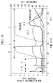
- Fig. 10 is a graph showing changes in the amounts of non-axisymmetric strains of the optical fibers 16_1, 16_2, and 16_3 in the initial pressurizing process.
- the initial pressurizing process refers to the process shown in Figs. 9 (c) and (d) .
- the amounts of non-axisymmetric strains refer to the amounts of strains into elliptical shapes caused by pressurization of the optical fibers 16, obtained based on the shape of the light spectrum.
- the vertical axis represents the pressure difference between the interior and exterior of the bag 40, the temperature, and the amount of non-axisymmetric strain
- the horizontal axis represents time. 0 atm along the vertical axis corresponds to the case where the pressure inside the bag 40 was the atmospheric pressure and a pressure was not applied from the outside.
- Region A in Fig. 10 corresponds to the case where the interior of the bag 40 was vacuum-pumped ( Fig. 9(c) ), and the amounts of non-axisymmetric strains of the optical fibers 16_2 and 16_3 increased when the pressure was changed to 1 atm.
- a peak occurred in the initial stage. The reason is as follows. When a pressure was applied to the optical fiber sensors 16_2 and 16_3, although the amounts of non-axisymmetric strains become maximum in the initial stage, since the optical fiber sensors 16_2 and 16_3 entered the solid elements 30 due to the pressure, the stress applied to the optical fiber sensors 16_2 and 16_3 was alleviated, whereby the amounts of non-axisymmetric strains decreased.
- Region B corresponds to the case where the vacuum interior of the bag 40 was opened, whereby the non-axisymmetric strains of the optical fibers 16_2 and 16_3 were eliminated.
- Region B was provided experimentally in order to measure the non-axisymmetric strains of the optical fibers 16_2 and 16_3, and the above operation is not performed in the actual initial pressurizing process.
- Region C corresponds to the case where the vacuum pumping of the interior of the bag 40 was resumed, in which the amounts of non-axisymmetric strains of the optical fibers 16_2 and 16_3 increased, similarly to region A.
- Region D corresponds to the case where autoclave pressurization was performed ( Fig. 9(d) ), with a maximum pressure of 7 atm.
- the amounts of non-axisymmetric strains of the optical fibers 16_2 and 16_3 increased as the pressure was applied.
- the response of the optical fiber 16_2 was slower than the response of the optical fiber 16_3.
- Region E corresponds to the case where the pressure was removed, at which time the pressure decreased to 1 atm and the non-axisymmetric strains of the optical fibers 16_2 and 16_3 were eliminated. Region E was provided experimentally in order to measure the non-axisymmetric strains of the optical fibers 16_2 and 16_3, and the above operation is not performed in the actual initial pressurizing process.
- Region F corresponds to the case where the autoclave pressurization was resumed, at which time the amounts of non-axisymmetric strains of the optical fibers 16_2 and 16_3 increased, similarly to region D.
- the amounts of non-axisymmetric strains of the optical fibers 16_2 and 16_3 increased as the pressure was applied. However, when heating was started, the adhesive 14 gradually softened, so that the stress applied to the optical fibers 16_2 and 16_3 was alleviated, whereby the amounts of non-axisymmetric strains gradually decreased.
- test results shown in Fig. 10 demonstrate that the sensitivity of the optical fiber 16_3, in association with which the solid element 30 was inserted in the gap with the adhesive 14, was higher than the sensitivity of the optical fiber 16_2, in association with which the solid element 30 was inserted in the gap with the laminate 12B. This is because the solid element 30 inserted in the gap with the adhesive 14 more strongly hinders the associated optical fiber 16 from entering the adhesive 14 compared with the case where the solid element 30 was inserted in the gap with the laminate 12B.
- the solid elements 30 between the optical fibers 16 and the adhesive 14. Accordingly, in the second embodiment, it is possible to more accurately determine whether members are bonded together appropriately even during the bonding process of the bonded structure 10 in which the laminates 12A and 12B have not yet been bonded together or are being bonded together.
- Fig. 11 is a graph showing changes in the amounts of non-axisymmetric strains of the optical fibers 16_1, 16_2, and 16_3 in a heating and cooling process.
- the initial pressurizing process is shown in Figs. 9 (e) and (f) .
- the vertical axis represents the amount of non-axisymmetric strain and the temperature
- the horizontal axis represents time
- the reason for this is as follows. Since the adhesive 14 softened when heated, the optical fiber 16_1 entered the adhesive 14 instead of a stress being applied thereto. On the other hand, the optical fibers 16_2 and 16_3 were hindered from entering the adhesive 14 by the solid elements 30, so that a stress was applied to the optical fibers 16_2 and 16_3, whereby the shapes thereof changed.
- the adhesive 14 further softened as the temperature rose, and the stress applied to the optical fibers 16_2 and 16_3 was alleviated, so that the amounts of non-axisymmetric strains gradually decreased.
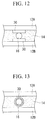
- Fig. 12 is a vertical sectional view showing an example in which solid elements 30 are inserted between the optical fiber 16 and the laminate 12A and the optical fiber 16 and the laminate 12B. In the case of this mode, it is necessary to insert the solid elements 30 such that the optical fiber 16 becomes embedded in the adhesive 14 after the bonded structure 10 is hardened.
- Fig. 13 is a vertical sectional view showing an example where the solid element 30 has a tube shape instead of a plate shape. Also in the case of this mode, it is necessary to insert the solid element 30 such that the optical fiber 16 becomes embedded in the adhesive 14 after the bonded structure 10 is hardened.
- the solid element 30 is inserted between the optical fiber 16 and at least one of the laminate 12A and the laminate 12B.
- the bonded structure 10 Accordingly, with the bonded structure 10 according to the second embodiment, it is possible to determine whether members are bonded together appropriately even when the laminates 12A and 12B have not yet been bonded together or are being bonded together.
- the bonded members are the laminates 12A and 12B of carbon fiber composite materials, without limitation thereto, according to the present invention, for example, the bonded members may be fiber-reinforced resin-based composite materials reinforced with glass fibers, etc. or metallic materials such as aluminum alloys.
Landscapes
- Physics & Mathematics (AREA)
- General Physics & Mathematics (AREA)
- Immunology (AREA)
- Pathology (AREA)
- Chemical & Material Sciences (AREA)
- Analytical Chemistry (AREA)
- Biochemistry (AREA)
- General Health & Medical Sciences (AREA)
- Health & Medical Sciences (AREA)
- Life Sciences & Earth Sciences (AREA)
- Optical Transform (AREA)
- Investigating Or Analysing Materials By Optical Means (AREA)
- Laminated Bodies (AREA)
- Joining Of Glass To Other Materials (AREA)
- Examining Or Testing Airtightness (AREA)
- Lining Or Joining Of Plastics Or The Like (AREA)
- Light Guides In General And Applications Therefor (AREA)
Abstract
Description
- This invention relates to bonded structures and bonding-condition detecting methods.
- Conventionally, carbon fiber composite materials have been used, for example, in airplane structures that require weight reduction.
- As a method of monitoring resin hardening of a carbon fiber composite material, there is a method that uses an optical fiber having a grating sensor provided inside, as described in
Patent Literature 1. - Generally, members such as carbon fiber composite materials are joined together by using fasteners such as rivets or bolts.
- When joining members together, although it is optimal to use an adhesive from the viewpoints of weight reduction, working efficiency, etc., this requires the evaluation of bonding quality. The evaluation of bonding quality is conducted, for example, by way of ultrasonic testing after members are joined together by using an adhesive.
- {PTL 1}
Japanese Translation ofPCT International Application, Publication No. 2000-501176 - With ultrasonic testing, however, although it is possible to detect the occurrence of a void in an adhesive layer or a defect such as detachment of a member, it is not possible to evaluate the strength of bonding. This is because the strength of bonding depends on factors such as a pressure applied to members during bonding but it is not possible to inspect the pressure in ultrasonic testing. Furthermore, ultrasonic testing requires time and labor and also requires a certified inspector.
- Furthermore, in the case where the members are carbon fiber composite materials, for example, the members are bonded together during autoclave shaping. During autoclave shaping, although the pressure in the autoclave and the pressure in the bag are measured, the pressure at the bonding region itself is not measured.
- In consideration of these facts, in the case where members are joined together by bonding, structures are designed with considerable safety margins, or fasters are used for joining instead of adhesive bonding at regions where safety is emphasized.
- The present invention has been made in view of this situation, and it is an object thereof to provide a bonded structure and a bonding-condition detecting method that make it possible to determine whether members are bonded together appropriately.
- In order to solve the problem described above, a bonded structure and a bonding-condition detecting method according to the present invention employ the following solutions.
- A bonded structure according to a first aspect of the present invention includes a first member, a second member, an adhesive that bonds together the first member and the second member, and an optical fiber sandwiched between the first member and the second member, and the bonding condition between the first member and the second member is detected based on birefringence of the optical fiber.
- With this configuration, the first member and the second member are bonded together by using the adhesive. The first member and the second member are bonded together by applying an appropriate pressure with the adhesive sandwiched therebetween. The optical fiber sandwiched between the first member and the second member is used to detect the bonding condition between the first member and the second member based on birefringence.
- When a pressure is not applied to the optical fiber, the light spectrum has only one peak. On the other hand, when a pressure is applied to the optical fiber only from a predetermined direction, the sectional shape of the optical fiber, which was originally a circular shape, is deformed to become, for example, an elliptical shape (a flattened circular shape or an elongated circular shape), so that the shape of the light spectrum changes so as to have multiple (e.g., two) peaks. This is birefringence of the optical fiber, and the optical fiber is used as a pressure sensor.
- That is, when the first member and the second member are bonded together by appropriately applying a pressure, a pressure is applied to the optical fiber from both directions associated with the first member and the second member. Thus, the light spectrum of the optical fiber exhibits multiple peaks due to birefringence. The bonding condition between the first member and the second member is detected by using the optical fiber as a pressure sensor as described above.
- As described above, with this configuration, since the bonding condition between the first member and the second member is detected based on birefringence of the optical fiber, it is possible to determine whether these members are bonded together appropriately.
- In the first aspect, preferably, the first member and the second member are laminates of carbon fiber composite materials, and the bonding condition between the first member and the second member is detected based on birefringence of the optical fiber in a case where the first member and the second member are bonded together by using a pressurizing device.
- With this configuration, it is possible to determine whether members are bonded together appropriately in a case where the laminates of carbon fiber composite materials are bonded together as members.
- In the first aspect, preferably, the first member and the second member sandwiching the adhesive and the optical fiber are covered with a bag, the pressure inside the bag is set to less than the atmospheric pressure, and the bonding condition between the first member and the second member is detected based on birefringence of the optical fiber while a pressure is being applied inside the autoclave.
- With this configuration, it is possible to determine more appropriately whether members are bonded together appropriately in a case where the laminates of carbon fiber composite materials are bonded together as members.
- In the first aspect, preferably, a solid object is inserted between the optical fiber and at least one of the first member and the second member.
- With this configuration, it is possible to determine whether members are bonded together appropriately even when the members have not yet been bonded together or are being bonded together.
- In the first aspect, preferably, the solid object is inserted between the optical fiber and the adhesive.
- With this configuration, it is possible to determine more accurately whether members are bonded together appropriately even when the members have not yet been bonded together or are being bonded together.
- In the first aspect, preferably, the solid object is formed by hardening an adhesive of the same kind as the adhesive.
- With this configuration, since the solid object and the adhesive become integrated in the bonding process of the bonded structure, the solid object does not become an impurity in the bonded structure.
- A bonding-condition detecting method according to a second aspect of the present invention includes a first step of bonding together a first member and a second member by using an adhesive with an optical fiber sandwiched therebetween and a second step of detecting the bonding condition between the first member and the second member based on birefringence of the optical fiber.
- According to the present invention, a superior advantage is afforded in that it is possible to determine whether members are bonded together appropriately.
-
- {
Fig. 1 }
Fig. 1 is an exploded perspective view showing a bonded structure according to a first embodiment of the present invention. - {
Fig. 2 }
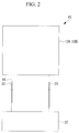
Fig. 2 is a schematic plan view of a measurement and diagnosis unit according to the first embodiment of the present invention. - {
Fig. 3 }
Fig. 3 is a diagram showing the light spectrum in a case where a pressure is not applied to an optical fiber according to the first embodiment of the present invention. - {
Fig. 4 }
Fig. 4 is a diagram showing the light spectrum in a case where a pressure is applied to the optical fiber according to the first embodiment of the present invention. - {
Fig. 5 }
Fig. 5 is a graph showing changes in the shape of the light spectrum of the optical fiber in a process in which the laminates to be bonded according to the first embodiment of the present invention were covered with a bag, the pressure inside the bag was set to less than the atmospheric pressure, and the pressure and temperature inside an autoclave were raised. - {
Fig. 6 }
Fig. 6 is a graph showing changes in the shape of the light spectrum of the optical fiber in a process in which the laminates to be bonded according to the first embodiment of the present invention were not covered with a bag, and the pressure and temperature inside an autoclave were raised. - {
Fig. 7 }
Fig. 7 is an exploded perspective view showing a bonded structure according to a second embodiment of the present invention. - {
Fig. 8 }
Fig. 8 is an exploded vertical sectional view of the bonded structure according to the second embodiment of the present invention. - {
Fig. 9 }
Fig. 9 is a schematic illustration showing a bonding process of the bonded structure according to the second embodiment of the present invention. - {
Fig. 10 }
Fig. 10 is a graph showing changes in the amounts of non-axisymmetric strains of optical fibers in an initial pressurizing process according to the second embodiment of the present invention. - {
Fig. 11 }
Fig. 11 is a graph showing changes in the amounts of non-axisymmetric strains of optical fibers in a heating and cooling process according to the second embodiment of the present invention. - {
Fig. 12 }
Fig. 12 is a vertical sectional view of the bonded structure according to the second embodiment of the present invention. - {
Fig. 13 }
Fig. 13 is a vertical sectional view of the bonded structure according to the second embodiment of the present invention. - Now, an embodiment of a bonded structure and a bonding-condition detecting method according to the present invention will be described with reference to the drawings.
- Here, a first embodiment of the present invention will be described.
-
Fig. 1 is an exploded perspective view showing a bonded structure according to the first embodiment. In the first embodiment, as an example, bonded members are laminates of carbon fiber composite materials. Furthermore, for example, multiple bondedstructures 10 are combined for use as structural members of airplanes, automobiles, wind turbines, etc. - The bonded
structure 10 includes alaminate 12A, a laminate 12B, an adhesive 14 that bonds together the laminate 12A and the laminate 12B, and anoptical fiber 16 sandwiched between the laminate 12A and the laminate 12B. Theoptical fiber 16 is used as a sensor (optical fiber sensor) for detecting the bonding condition between the laminate 12A and the laminate 12B based on birefringence. For example, theoptical fiber 16 is a single mode fiber with a cladding diameter of 125 µm and a circular cross section. - The adhesive 14 is formed, for example, as a bonding layer. Although there is no particular limitation as to the kind of the adhesive 14, for example, an epoxy-resin-based adhesive can be used.
- Before the
laminates - Furthermore, although the planar shapes of the
laminates Fig. 1 are rectangular, this is just an example, and the planar shapes of thelaminates laminates - The
optical fiber 16 shown inFig. 1 is bent multiple times, and alight input end 16A and alight output end 16B thereof protrude from the same sides of thelaminates optical fiber 16 need not necessarily be sandwiched in a bent form, and theinput end 16A andoutput end 16B may protrude from different sides of thelaminates optical fiber 16. - Furthermore, although the
optical fiber 16 shown inFig. 1 is sandwiched between the laminate 12A and the laminate 12B so as to be embedded in the adhesive 14, there is no limitation to this form, and theoptical fiber 16 need not be embedded in the adhesive 14. - Furthermore, as shown in
Fig. 2 , the input ends 16A and 16B of theoptical fiber 16 are individually connected to a measurement anddiagnosis unit 22 viaconnectors 20. The measurement anddiagnosis unit 22 receives light having a predetermined wavelength from theinput end 16A of theoptical fiber 16 and detects light that has been transmitted through theoptical fiber 16 at theoutput end 16B to obtain a light spectrum. - The
laminates laminates optical fiber 16. - When the pressure is not applied to the
optical fiber 16, the light spectrum has only one peak, as shown inFig. 3 . On the other hand, when a pressure is applied to theoptical fiber 16 only from a predetermined direction, the sectional shape of theoptical fiber 16, which was originally a circular shape, is deformed to become, for example, an elliptical shape (a flattened circular shape or an elongated circular shape), as shown inFig. 4 . Thus, the shape of the light spectrum changes so as to have multiple (e.g., two) peaks. This is birefringence of theoptical fiber 16. - That is, when the
laminates optical fiber 16 from both directions associated with thelaminate 12A and the laminate 12B, and the light spectrum of theoptical fiber 16 exhibits multiple peaks due to birefringence. By using theoptical fiber 16 as a pressure sensor as described above, it becomes possible to detect the bonding condition between thelaminates - In the first embodiment, in which bonded members are the
laminates laminates optical fiber 16. Thus, in the first embodiment, it is possible to determine whether members are bonded together appropriately when bonding together thelaminates - Next, test results for the first embodiment will be described by using
Figs. 5 and6 . -
Figs. 5 and6 show the results of a test in which unhardened adhesive 14 was sandwiched between thelaminates optical fiber 16 was embedded between the adhesive 14 and thelaminate 12A and the laminate 12B. -
Fig. 5 is a graph showing changes in the light spectrum of theoptical fiber 16 in a process in which thelaminates - As shown in
Fig. 5 , before a pressure was applied inside the autoclave, only one peak appeared in the light spectrum. While a pressure was being applied, the peak in the light spectrum became lower and divided into two, and after the pressure was applied, two apparent peaks appeared in the light spectrum. The two peaks indicate that the sectional shape of theoptical fiber 16, which was originally a circular shape, was deformed and changed to an elliptical shape due to the pressure applied to theoptical fiber 16, which resulted in birefringence. That is, the peaks indicate that a pressure was applied to thelaminates - In
Fig. 5 , the peak position shifts to the higher frequency side in the process before, during, and after pressurization. This is because the temperature of the bondedstructure 10 rose due to pressurization. - Then, the temperature was raised in the next step. Referring to
Fig. 5 , the temperature was higher during temperature rise_2 than during temperature rise_1. - While the temperature was being raised, the peak of the light spectrum converged back to one. This is because the viscosity of the adhesive 14 decreased due to the temperature rise, so that the non-axisymmetric pressure applied to the
optical fiber 16 only from a predetermined direction decreased, whereby the deformation of the sectional shape of theoptical fiber 16 was alleviated. Even when the pressure applied to theoptical fiber 16 decreased, a pressure required for bonding was maintained at thelaminates - Then, the adhesive 14 was hardened after the temperature rise, whereby the
laminates - On the other hand,
Fig. 6 shows changes in the light spectrum of theoptical fiber 16 in a process in which thelaminates laminates - As shown in
Fig. 6 , the shape of the light spectrum did not substantially change and remained the same before and after applying a pressure inside the autoclave, without the peak dividing into two. - Furthermore, even during the temperature rise, the shape of the light spectrum did not change except that the peak position shifted to the higher frequency side.
- This indicates that, with the hydrostatic pressure, a sufficient pressure required for bonding was not applied to the
laminates - The results shown in
Figs. 5 and6 demonstrate that it is preferable for thebonding structure 10 according to the first embodiment to cover thelaminates optical fiber 16 with a bag and then to reduce the pressure inside the bag to less than the atmospheric pressure and to detect the bonding condition of thelaminates optical fiber 16 while a pressure is being applied inside the autoclave. - In the conventional manufacturing process, the bag is vacuum-pumped and is maintained in that state until shaping is finished or is vacuum-pumped and is opened to the atmosphere when the pressure becomes 1 atm or higher. Furthermore, the autoclave is opened to the atmosphere when the adhesive 14 is hardened, cooling is started, and the temperature becomes 60 °C or lower.
- On the other hand, in the test for the first embodiment, shown in
Fig. 5 , the bag is vacuum-pumped and is then opened to the atmosphere before cooling is started after the adhesive 14 is hardened. Furthermore, the autoclave is opened to the atmosphere before cooling is started after the adhesive 14 is hardened. - Accordingly, a pressure is applied continuously to the
laminates laminates - Furthermore, it was confirmed that when cooling was started with a certain pressure applied, the sectional shape of the
optical fiber 16 again changed to an elliptical shape, which resulted in birefringence. In accordance with this phenomenon, multiple (two) peaks again appeared in the light spectrum. By utilizing this phenomenon, it is possible to combine multiple bondedstructures 10, for example, for use as a structural member of an airplane, and to detect the detachment status between thelaminates laminates optical fiber 16 is alleviated, so that the light spectrum exhibits only one peak. - Now, a second embodiment of the present invention will be described.
-
Fig. 7 is an exploded perspective view showing a bondedstructure 10 according to the second embodiment.Fig. 8 is an exploded vertical sectional view of the bondedstructure 10 according to the second embodiment. - As shown in
Figs. 7 and 8 , in the bondedstructure 10 according to the second embodiment,solid elements 30, which are solid objects, are inserted between theoptical fiber 16 and at least one of the laminate 12A and the laminate 12B. - The example shown in
Figs. 7 and 8 is a configuration for the purpose of testing, and in order to measure the difference in changes of the shape of the light spectrum depending on the presence or absence of thesolid elements 30, which will be described later, an optical fiber 16_1 with no associated insertedsolid element 30 and optical fibers 16_2 and 16_3 with associated insertedsolid elements 30 are provided. Furthermore, in order to measure the temperature in the vicinity of each of theoptical fibers 16, atemperature sensor 32 is disposed for each of theoptical fibers 16 on the top face of thelaminate 12A. For example, thetemperature sensor 32 is a thermocouple. - A
solid element 30 is inserted between the optical fiber 16_2 and the laminate 12B. Furthermore, asolid element 30 is inserted between the optical fiber 16_3 and the adhesive 14. - For example, the
solid elements 30 are made of hardened adhesive, and examples thereof include chemical setting, thermosetting, and thermoplastic adhesives. - A chemical setting adhesive is an adhesive whose hardening response progresses, for example, when two liquids, namely, a main agent and a hardening agent, are mixed together. An example thereof is EA9394 from Henkel.
- A thermosetting adhesive is an adhesive whose hardening response progresses when heat is applied to the adhesive from outside. An example thereof is FM300-2 from Cytec.
- A thermoplastic adhesive is an adhesive whose hardening response progresses when a polymerization reaction occurs due to heat applied to the adhesive and then heat is dissipated. An example thereof is PPS resin (Poly Phenylene Sulfide Resin).
- Furthermore, as the
solid elements 30, shims such as unhardened prepregs used to adjust the gaps at the bonding regions may be used. - In the second embodiment, as an example of the
solid elements 30, an element formed by hardening FM300-2 from Cytec, mentioned above, was used. In the second embodiment, as an example, FM300-2 from Cytec was also used as the adhesive 14. - Since the
solid elements 30 are formed by hardening an adhesive of the same kind as the adhesive 14 as described above, so that thesolid elements 30 and the adhesive 14 are integrated (assimilated) in the bonding process of the bondedstructure 10, thesolid elements 30 do not become impurities in the bondedstructure 10, and the strength in the vicinity of the regions where thesolid elements 30 are inserted is not reduced. - Furthermore, the choice among chemical setting, thermosetting, thermoplastic, and other types of adhesive for use as the
solid elements 30 is determined suitably in accordance with the shape of thesolid elements 30, the kind of the adhesive 14 used, etc. - Furthermore, for example, the size of the
solid elements 30 is a plate shape of 20 mm × 5 mm, and their lengthwise direction is aligned with the directions of theoptical fibers 16. Thesolid elements 30 need not be inserted in association with the entireoptical fibers 16, and it suffices to insert thesolid elements 30 in regions associated with sensing portions of theoptical fibers 16. The shape of thesolid elements 30 need not be a rectangular shape and may be a square shape, a polygonal shape other than a rectangular shape, a circular shape, etc. Furthermore, the thickness of thesolid elements 30 is chosen such that the total thickness of theoptical fibers 16 and thesolid elements 30 is less than the thickness of the bonding layer formed of the adhesive 14. -
Fig. 9 is a schematic illustration showing the bonding process of the bondedstructure 10. - First, to form the bonded
structure 10, thelaminate 12A, the adhesive 14, theoptical fibers 16, and the laminate 12B are stacked in that order (Fig. 9(a) ). - Then, the laminated assembly is covered with a bag 40 (
Fig. 9(b) ). - Then, the interior of the
bag 40 is vacuum-pumped to set the internal pressure to less than the atmospheric pressure (Fig. 9(c) ). This results in a pressure difference of about 1 atm between the interior and exterior of thebag 40. - Then, a predetermined pressure is applied from the outside of the bag 40 (autoclave pressurization) (
Fig. 9(d) ). This results in a pressure difference exceeding about 1 atm between the interior and exterior of thebag 40. - Then, heat is applied at a predetermined temperature from the outside of the bag 40 (autoclave heating) (
Fig. 9(e) ). - Then, after cooling for a predetermined period, the hardening of the adhesive 14 is finished, whereby the bonded
structure 10 is formed (Fig. 9(f) ). -
Fig. 10 is a graph showing changes in the amounts of non-axisymmetric strains of the optical fibers 16_1, 16_2, and 16_3 in the initial pressurizing process. The initial pressurizing process refers to the process shown inFigs. 9 (c) and (d) . The amounts of non-axisymmetric strains refer to the amounts of strains into elliptical shapes caused by pressurization of theoptical fibers 16, obtained based on the shape of the light spectrum. - In
Fig. 10 , the vertical axis represents the pressure difference between the interior and exterior of thebag 40, the temperature, and the amount of non-axisymmetric strain, and the horizontal axis represents time. 0 atm along the vertical axis corresponds to the case where the pressure inside thebag 40 was the atmospheric pressure and a pressure was not applied from the outside. - Furthermore, there were no significant differences among the temperatures measured by the
temperature sensors 30 associated with the optical fibers 16_1, 16_2, and 16_3, and the temperatures changed substantially the same over time. - Region A in
Fig. 10 corresponds to the case where the interior of thebag 40 was vacuum-pumped (Fig. 9(c) ), and the amounts of non-axisymmetric strains of the optical fibers 16_2 and 16_3 increased when the pressure was changed to 1 atm. In the amounts of non-axisymmetric strains in region A, a peak occurred in the initial stage. The reason is as follows. When a pressure was applied to the optical fiber sensors 16_2 and 16_3, although the amounts of non-axisymmetric strains become maximum in the initial stage, since the optical fiber sensors 16_2 and 16_3 entered thesolid elements 30 due to the pressure, the stress applied to the optical fiber sensors 16_2 and 16_3 was alleviated, whereby the amounts of non-axisymmetric strains decreased. - Region B corresponds to the case where the vacuum interior of the
bag 40 was opened, whereby the non-axisymmetric strains of the optical fibers 16_2 and 16_3 were eliminated. Region B was provided experimentally in order to measure the non-axisymmetric strains of the optical fibers 16_2 and 16_3, and the above operation is not performed in the actual initial pressurizing process. - Region C corresponds to the case where the vacuum pumping of the interior of the
bag 40 was resumed, in which the amounts of non-axisymmetric strains of the optical fibers 16_2 and 16_3 increased, similarly to region A. - For both regions A and C, the sensitivity of the optical fiber 16_3, in association with which the
solid element 30 was inserted in the gap with the adhesive 14, was higher than the sensitivity of the optical fiber 16_2, in association with which thesolid element 30 was inserted in the gap with the laminate 12B. - Therefore, it is preferred to insert the
solid elements 30 between theoptical fibers 16 and the adhesive 14. This makes it possible to determine more accurately whether members are bonded together appropriately even during the bonding process of the bondedstructure 10 in which thelaminates - Region D corresponds to the case where autoclave pressurization was performed (
Fig. 9(d) ), with a maximum pressure of 7 atm. The amounts of non-axisymmetric strains of the optical fibers 16_2 and 16_3 increased as the pressure was applied. The response of the optical fiber 16_2 was slower than the response of the optical fiber 16_3. - Region E corresponds to the case where the pressure was removed, at which time the pressure decreased to 1 atm and the non-axisymmetric strains of the optical fibers 16_2 and 16_3 were eliminated. Region E was provided experimentally in order to measure the non-axisymmetric strains of the optical fibers 16_2 and 16_3, and the above operation is not performed in the actual initial pressurizing process.
- Region F corresponds to the case where the autoclave pressurization was resumed, at which time the amounts of non-axisymmetric strains of the optical fibers 16_2 and 16_3 increased, similarly to region D.
- The amounts of non-axisymmetric strains of the optical fibers 16_2 and 16_3 increased as the pressure was applied. However, when heating was started, the adhesive 14 gradually softened, so that the stress applied to the optical fibers 16_2 and 16_3 was alleviated, whereby the amounts of non-axisymmetric strains gradually decreased.
- Changes in the amount of non-axisymmetric strain of the optical fiber 16_1, in association with which no
solid element 30 was inserted, were smaller compared with those of the optical fibers 16_2 and 16_3. - The reason is that, since no
solid element 30 was inserted in association with the optical fiber 16_1, when a pressure was applied, the optical fiber 16_1 entered the adhesive 14 instead of a stress being applied thereto, so that the shape of the optical fiber 16_1 did not change. On the other hand, the optical fibers 16_2 and 16_3, in association with which thesolid elements 30 were inserted, were hindered from entering the adhesive 14 by thesolid elements 30. Thus, a stress was applied to the optical fibers 16_2 and 16_3, and the shapes thereof changed, which resulted in changes in the amounts of non-axisymmetric strains. This made it possible to determine whether members are bonded together appropriately even during the bonding process of the bondedstructure 10. - Furthermore, the test results shown in
Fig. 10 demonstrate that the sensitivity of the optical fiber 16_3, in association with which thesolid element 30 was inserted in the gap with the adhesive 14, was higher than the sensitivity of the optical fiber 16_2, in association with which thesolid element 30 was inserted in the gap with the laminate 12B. This is because thesolid element 30 inserted in the gap with the adhesive 14 more strongly hinders the associatedoptical fiber 16 from entering the adhesive 14 compared with the case where thesolid element 30 was inserted in the gap with the laminate 12B. - Therefore, it is preferred to insert the
solid elements 30 between theoptical fibers 16 and the adhesive 14. Accordingly, in the second embodiment, it is possible to more accurately determine whether members are bonded together appropriately even during the bonding process of the bondedstructure 10 in which thelaminates -
Fig. 11 is a graph showing changes in the amounts of non-axisymmetric strains of the optical fibers 16_1, 16_2, and 16_3 in a heating and cooling process. The initial pressurizing process is shown inFigs. 9 (e) and (f) . - In
Fig. 11 , the vertical axis represents the amount of non-axisymmetric strain and the temperature, and the horizontal axis represents time. - It is to be noted that although the amounts of non-axisymmetric strains of the optical fibers 16_2 and 16_3 increased and decreased even before heating was started (from 0 to just after 100 minutes), the increases and decreases were attributable to large variations in the light spectrum due to vacuum pumping, pressurizing, etc. of the
bag 40, which resulted in incorrect calculation of the non-axisymmetric strains. - As shown in
Fig. 11 , in the early stage of heating, the amounts of non-axisymmetric strains of the optical fibers 16_2 and 16_3 were large. On the other hand, there was no significant change in the amount of non-axisymmetric strain of the optical fiber 16_1. - The reason for this is as follows. Since the adhesive 14 softened when heated, the optical fiber 16_1 entered the adhesive 14 instead of a stress being applied thereto. On the other hand, the optical fibers 16_2 and 16_3 were hindered from entering the adhesive 14 by the
solid elements 30, so that a stress was applied to the optical fibers 16_2 and 16_3, whereby the shapes thereof changed. - However, the adhesive 14 further softened as the temperature rose, and the stress applied to the optical fibers 16_2 and 16_3 was alleviated, so that the amounts of non-axisymmetric strains gradually decreased.
- As for the optical fiber 16_1, in association with which no
solid element 30 was inserted, there was no significant change in the amount of non-axisymmetric strain even when the temperature rose. - When heating was finished, the temperature fell, and cooling was started, the adhesive 14 hardened, and the stress applied to the optical fibers 16_1, 16_2, and 16_3 increased. Accordingly, the amounts of non-axisymmetric strains of the optical fibers 16_1, 16_2, and 16_3 increased.
-
Fig. 12 is a vertical sectional view showing an example in whichsolid elements 30 are inserted between theoptical fiber 16 and thelaminate 12A and theoptical fiber 16 and the laminate 12B. In the case of this mode, it is necessary to insert thesolid elements 30 such that theoptical fiber 16 becomes embedded in the adhesive 14 after the bondedstructure 10 is hardened. -
Fig. 13 is a vertical sectional view showing an example where thesolid element 30 has a tube shape instead of a plate shape. Also in the case of this mode, it is necessary to insert thesolid element 30 such that theoptical fiber 16 becomes embedded in the adhesive 14 after the bondedstructure 10 is hardened. - As described hereinabove, in the bonded
structure 10 according to the second embodiment, thesolid element 30 is inserted between theoptical fiber 16 and at least one of the laminate 12A and the laminate 12B. - Accordingly, with the bonded
structure 10 according to the second embodiment, it is possible to determine whether members are bonded together appropriately even when thelaminates - Although the present invention has been described in the context of the above-described embodiments, the technical scope of the present invention is not limited to the scopes of the above-described embodiments. It is possible to make various modifications and improvements to the above-described embodiments without departing from the scope of the invention, and the modes involving such modifications and improvements are also included in the technical scope of the present invention.
- For example, although the above embodiments have been described in the context of examples where the bonded members are the
laminates -
- 10
- Bonded structure
- 12A
- Laminate
- 12B
- Laminate
- 14
- Adhesive
- 16
- Optical fiber
- 30
- Solid element
Claims (7)
- A bonded structure comprising:a first member;a second member;an adhesive that bonds together the first member and the second member; andan optical fiber sandwiched between the first member and the second member,wherein the bonding condition between the first member and the second member is detected based on birefringence of the optical fiber.
- A bonded structure according to Claim 1,
wherein the first member and the second member are laminates of carbon fiber composite materials, and
wherein the bonding condition between the first member and the second member is detected based on birefringence of the optical fiber in a case where the first member and the second member are bonded together by using a pressurizing device. - A bonded structure according to Claim 2, wherein the first member and the second member sandwiching the adhesive and the optical fiber are covered with a bag, the pressure inside the bag is set to less than the atmospheric pressure, and the bonding condition between the first member and the second member is detected based on birefringence of the optical fiber while a pressure is being applied inside the autoclave.
- A bonded structure according to any one of Claims 1 to 3, wherein a solid object is inserted between the optical fiber and at least one of the first member and the second member.
- A bonded structure according to Claim 4, wherein the solid object is inserted between the optical fiber and the adhesive.
- A bonded structure according to Claim 4 or 5, wherein the solid object is formed by hardening an adhesive of the same kind as the adhesive.
- A bonding-condition detecting method comprising:a first step of bonding together a first member and a second member by using an adhesive with an optical fiber sandwiched therebetween; anda second step of detecting the bonding condition between the first member and the second member based on birefringence of the optical fiber.
Applications Claiming Priority (2)
| Application Number | Priority Date | Filing Date | Title |
|---|---|---|---|
| JP2013102254 | 2013-05-14 | ||
| PCT/JP2014/054826 WO2014185119A1 (en) | 2013-05-14 | 2014-02-27 | Joined structure and method for detecting joined state |
Publications (3)
| Publication Number | Publication Date |
|---|---|
| EP3001178A1 true EP3001178A1 (en) | 2016-03-30 |
| EP3001178A4 EP3001178A4 (en) | 2017-01-11 |
| EP3001178B1 EP3001178B1 (en) | 2020-04-08 |
Family
ID=51898105
Family Applications (1)
| Application Number | Title | Priority Date | Filing Date |
|---|---|---|---|
| EP14797172.5A Active EP3001178B1 (en) | 2013-05-14 | 2014-02-27 | Bonded structure and bonding-condition detecting method |
Country Status (8)
| Country | Link |
|---|---|
| US (1) | US10145786B2 (en) |
| EP (1) | EP3001178B1 (en) |
| JP (1) | JP6174132B2 (en) |
| CN (1) | CN105143853B (en) |
| BR (1) | BR112015026520B1 (en) |
| CA (1) | CA2909484C (en) |
| RU (1) | RU2644613C2 (en) |
| WO (1) | WO2014185119A1 (en) |
Cited By (1)
| Publication number | Priority date | Publication date | Assignee | Title |
|---|---|---|---|---|
| EP3211399A4 (en) * | 2015-01-15 | 2017-11-29 | Mitsubishi Heavy Industries, Ltd. | Bonded structure, method for manufacturing same, and bonding state detection method |
Families Citing this family (3)
| Publication number | Priority date | Publication date | Assignee | Title |
|---|---|---|---|---|
| GB2529674B (en) * | 2014-08-28 | 2019-07-10 | Silixa Ltd | Flexible Substrate Fiber Optic Sensing Mat For Distributed Acoustic Sensing |
| CN106404065B (en) * | 2016-10-09 | 2019-05-07 | 山东大学 | A composite material encapsulated fiber grating sensor and its manufacturing method |
| JP6873073B2 (en) * | 2018-03-08 | 2021-05-19 | 三菱重工業株式会社 | Evaluation method and evaluation system |
Family Cites Families (26)
| Publication number | Priority date | Publication date | Assignee | Title |
|---|---|---|---|---|
| US5015842A (en) * | 1989-06-01 | 1991-05-14 | United Technologies Corporation | High density fiber optic damage detection system |
| US5281388A (en) * | 1992-03-20 | 1994-01-25 | Mcdonnell Douglas Corporation | Resin impregnation process for producing a resin-fiber composite |
| US5265475A (en) * | 1992-05-08 | 1993-11-30 | Rockwell International Corporation | Fiber optic joint sensor |
| US5399854A (en) * | 1994-03-08 | 1995-03-21 | United Technologies Corporation | Embedded optical sensor capable of strain and temperature measurement using a single diffraction grating |
| US5469520A (en) * | 1994-09-30 | 1995-11-21 | United Technologies Corporation | Compression-tuned fiber grating |
| US5770155A (en) * | 1995-11-21 | 1998-06-23 | United Technologies Corporation | Composite structure resin cure monitoring apparatus using an optical fiber grating sensor |
| US5828059A (en) * | 1996-09-09 | 1998-10-27 | Udd; Eric | Transverse strain measurements using fiber optic grating based sensors |
| JPH11300951A (en) | 1998-04-24 | 1999-11-02 | Canon Inc | Ink jet recording head and method of manufacturing the same |
| JP2000079693A (en) | 1998-06-26 | 2000-03-21 | Canon Inc | Ink jet print head and method of manufacturing the same |
| DE60033213T2 (en) | 1999-06-04 | 2007-10-25 | Canon K.K. | Liquid ejection head and liquid ejection device |
| JP2000343706A (en) | 1999-06-04 | 2000-12-12 | Canon Inc | Ink jet recording head and method of manufacturing the same |
| JP2001296110A (en) | 2000-04-17 | 2001-10-26 | Ntt Advanced Technology Corp | Stick type optical fiber sensor |
| US6720550B2 (en) * | 2000-06-22 | 2004-04-13 | Sandia National Laboratories | Sensor assembly |
| JP2002219108A (en) * | 2001-01-25 | 2002-08-06 | Computer Convenience:Kk | Optical ballistocardiograph |
| JP3647400B2 (en) | 2001-08-21 | 2005-05-11 | Tdk株式会社 | Compound optical element |
| JP4027258B2 (en) | 2003-04-18 | 2007-12-26 | 本田技研工業株式会社 | Debonding inspection method for bonded parts |
| JP2005164938A (en) * | 2003-12-02 | 2005-06-23 | Fujikura Ltd | Optical fiber and manufacturing method thereof, optical fiber manufacturing apparatus and optical connector |
| CN101087989B (en) | 2004-10-15 | 2011-06-08 | 摩根研究股份有限公司 | Embeddable polarization fiber optic sensor and method for monitoring structures |
| US7359586B2 (en) * | 2004-11-12 | 2008-04-15 | Gennadii Ivtsenkov | Fiber optic strain sensor and associated data acquisition system |
| JP2006352053A (en) * | 2005-05-20 | 2006-12-28 | Noritsu Koki Co Ltd | Laser light emitting device |
| DE102007008464B4 (en) * | 2007-02-19 | 2012-01-05 | Hottinger Baldwin Messtechnik Gmbh | Optical strain gauge |
| JP5354497B2 (en) | 2009-07-10 | 2013-11-27 | ニューブレクス株式会社 | Distributed fiber optic pressure sensor system |
| JP2011185790A (en) * | 2010-03-09 | 2011-09-22 | Ihi Corp | Delamination detecting method of laminating material and embedding method of optical fiber sensor |
| CN102841052A (en) | 2011-06-24 | 2012-12-26 | 日本板硝子株式会社 | Apparatus and method for measuring degree of cure of adhesive agent |
| JP5666998B2 (en) * | 2011-06-24 | 2015-02-12 | 日本板硝子株式会社 | Cured state measuring device and cured state measuring method |
| JP6258860B2 (en) * | 2011-11-15 | 2018-01-10 | ホッティンゲル・バルドヴィン・メステクニーク・ゲゼルシヤフト・ミト・ベシュレンクテル・ハフツング | FBG extension sensor for curved surfaces |
-
2014
- 2014-02-27 US US14/784,600 patent/US10145786B2/en active Active
- 2014-02-27 EP EP14797172.5A patent/EP3001178B1/en active Active
- 2014-02-27 WO PCT/JP2014/054826 patent/WO2014185119A1/en not_active Ceased
- 2014-02-27 BR BR112015026520-0A patent/BR112015026520B1/en not_active IP Right Cessation
- 2014-02-27 RU RU2015143136A patent/RU2644613C2/en active
- 2014-02-27 CN CN201480021967.6A patent/CN105143853B/en not_active Expired - Fee Related
- 2014-02-27 JP JP2015516958A patent/JP6174132B2/en active Active
- 2014-02-27 CA CA2909484A patent/CA2909484C/en active Active
Cited By (1)
| Publication number | Priority date | Publication date | Assignee | Title |
|---|---|---|---|---|
| EP3211399A4 (en) * | 2015-01-15 | 2017-11-29 | Mitsubishi Heavy Industries, Ltd. | Bonded structure, method for manufacturing same, and bonding state detection method |
Also Published As
| Publication number | Publication date |
|---|---|
| US20160069793A1 (en) | 2016-03-10 |
| WO2014185119A1 (en) | 2014-11-20 |
| CN105143853A (en) | 2015-12-09 |
| RU2644613C2 (en) | 2018-02-13 |
| CA2909484C (en) | 2019-08-20 |
| RU2015143136A (en) | 2017-06-23 |
| CA2909484A1 (en) | 2014-11-20 |
| CN105143853B (en) | 2019-01-04 |
| JP6174132B2 (en) | 2017-08-02 |
| JPWO2014185119A1 (en) | 2017-02-23 |
| US10145786B2 (en) | 2018-12-04 |
| BR112015026520A2 (en) | 2017-07-25 |
| EP3001178B1 (en) | 2020-04-08 |
| EP3001178A4 (en) | 2017-01-11 |
| BR112015026520B1 (en) | 2020-12-08 |
Similar Documents
| Publication | Publication Date | Title |
|---|---|---|
| CA2909484C (en) | Bonded structure and bonding-condition detecting method | |
| Wu et al. | Experimental investigation into transverse crashworthiness of CFRP adhesively bonded joints in vehicle structure | |
| KR102436693B1 (en) | Composite test specimen | |
| JP2000501176A (en) | Composite Structure Resin Curing Monitor Using Optical Fiber Grating Sensor | |
| EP2835252A1 (en) | Tooling and method for consolidating highly integrated composite structures | |
| Ali et al. | The effect of different tabbing methods on the damage progression and failure of carbon fiber reinforced composite material under tensile loading | |
| Paliwal et al. | Failure behavior of single-lap CFRP hybrid joints fastened using micro-bolt | |
| Correia et al. | Parametric study of composite curved adhesive joints | |
| EP2811289B1 (en) | Thermographic inspection system for composite wind turbine blade | |
| Kim | Impact resistance of composite scarf joints under load | |
| US8202378B2 (en) | Apparatus and method for enhancement of connection performance and fatigue detection | |
| Shah et al. | Investigation of composite bond thickness using optical fibers | |
| EP3211399B1 (en) | Bonded structure, method for manufacturing same, and bonding state detection method | |
| Meadows et al. | Distributed optical sensing in composite laminate adhesive bonds | |
| JP6083248B2 (en) | Manufacturing method of fiber reinforced thermoplastic resin integrated structure | |
| Czél et al. | Unidirectional hybrid composite overload sensors | |
| Moussa et al. | Analysis For Flat-Recess Head Countersink Composite Bolted Connection Under Tensile Loading | |
| Yilmaz et al. | APPLICATION OF HOOKE’S LAW TO ANGLE PLY LAMINA | |
| Abouzeida et al. | Design, manufacture and testing of an FBG-instrumented composite wing | |
| Takahashi et al. | Structural health monitoring of CFRP airframe structures using fiber-optic-based strain mapping | |
| US9534994B1 (en) | Methods, systems, and test articles for determining a flexibility value of a fastener | |
| US20160375667A1 (en) | Methods for creating thick laminate structures | |
| Allred et al. | Efficiency of double-lapped composite joints in bending | |
| Takahashi et al. | Life cycle strain monitoring of composite airframe structures by FBG sensors | |
| Barca et al. | The repair node analysis of the semi-monocoque aircraft structure |
Legal Events
| Date | Code | Title | Description |
|---|---|---|---|
| PUAI | Public reference made under article 153(3) epc to a published international application that has entered the european phase |
Free format text: ORIGINAL CODE: 0009012 |
|
| 17P | Request for examination filed |
Effective date: 20151014 |
|
| AK | Designated contracting states |
Kind code of ref document: A1 Designated state(s): AL AT BE BG CH CY CZ DE DK EE ES FI FR GB GR HR HU IE IS IT LI LT LU LV MC MK MT NL NO PL PT RO RS SE SI SK SM TR |
|
| AX | Request for extension of the european patent |
Extension state: BA ME |
|
| DAX | Request for extension of the european patent (deleted) | ||
| A4 | Supplementary search report drawn up and despatched |
Effective date: 20161214 |
|
| RIC1 | Information provided on ipc code assigned before grant |
Ipc: B32B 3/08 20060101ALI20161208BHEP Ipc: B32B 7/12 20060101ALI20161208BHEP Ipc: G01N 21/23 20060101AFI20161208BHEP Ipc: B32B 5/26 20060101ALI20161208BHEP |
|
| STAA | Information on the status of an ep patent application or granted ep patent |
Free format text: STATUS: EXAMINATION IS IN PROGRESS |
|
| 17Q | First examination report despatched |
Effective date: 20180307 |
|
| GRAP | Despatch of communication of intention to grant a patent |
Free format text: ORIGINAL CODE: EPIDOSNIGR1 |
|
| STAA | Information on the status of an ep patent application or granted ep patent |
Free format text: STATUS: GRANT OF PATENT IS INTENDED |
|
| RIC1 | Information provided on ipc code assigned before grant |
Ipc: G01N 21/23 20060101AFI20190927BHEP Ipc: B32B 7/12 20060101ALI20190927BHEP Ipc: G01D 5/353 20060101ALI20190927BHEP Ipc: B32B 3/08 20060101ALI20190927BHEP Ipc: B32B 5/26 20060101ALI20190927BHEP |
|
| INTG | Intention to grant announced |
Effective date: 20191023 |
|
| GRAS | Grant fee paid |
Free format text: ORIGINAL CODE: EPIDOSNIGR3 |
|
| GRAA | (expected) grant |
Free format text: ORIGINAL CODE: 0009210 |
|
| STAA | Information on the status of an ep patent application or granted ep patent |
Free format text: STATUS: THE PATENT HAS BEEN GRANTED |
|
| REG | Reference to a national code |
Ref country code: DE Ref legal event code: R081 Ref document number: 602014063565 Country of ref document: DE Owner name: THE UNIVERSITY OF TOKYO, JP Free format text: FORMER OWNER: MITSUBISHI HEAVY INDUSTRIES, LTD., TOKYO, JP Ref country code: DE Ref legal event code: R081 Ref document number: 602014063565 Country of ref document: DE Owner name: MITSUBISHI HEAVY INDUSTRIES, LTD., JP Free format text: FORMER OWNER: MITSUBISHI HEAVY INDUSTRIES, LTD., TOKYO, JP |
|
| AK | Designated contracting states |
Kind code of ref document: B1 Designated state(s): AL AT BE BG CH CY CZ DE DK EE ES FI FR GB GR HR HU IE IS IT LI LT LU LV MC MK MT NL NO PL PT RO RS SE SI SK SM TR |
|
| REG | Reference to a national code |
Ref country code: AT Ref legal event code: REF Ref document number: 1255047 Country of ref document: AT Kind code of ref document: T Effective date: 20200415 Ref country code: CH Ref legal event code: EP |
|
| REG | Reference to a national code |
Ref country code: IE Ref legal event code: FG4D |
|
| REG | Reference to a national code |
Ref country code: DE Ref legal event code: R096 Ref document number: 602014063565 Country of ref document: DE |
|
| REG | Reference to a national code |
Ref country code: NL Ref legal event code: MP Effective date: 20200408 |
|
| REG | Reference to a national code |
Ref country code: LT Ref legal event code: MG4D |
|
| PG25 | Lapsed in a contracting state [announced via postgrant information from national office to epo] |
Ref country code: LT Free format text: LAPSE BECAUSE OF FAILURE TO SUBMIT A TRANSLATION OF THE DESCRIPTION OR TO PAY THE FEE WITHIN THE PRESCRIBED TIME-LIMIT Effective date: 20200408 Ref country code: NL Free format text: LAPSE BECAUSE OF FAILURE TO SUBMIT A TRANSLATION OF THE DESCRIPTION OR TO PAY THE FEE WITHIN THE PRESCRIBED TIME-LIMIT Effective date: 20200408 Ref country code: GR Free format text: LAPSE BECAUSE OF FAILURE TO SUBMIT A TRANSLATION OF THE DESCRIPTION OR TO PAY THE FEE WITHIN THE PRESCRIBED TIME-LIMIT Effective date: 20200709 Ref country code: NO Free format text: LAPSE BECAUSE OF FAILURE TO SUBMIT A TRANSLATION OF THE DESCRIPTION OR TO PAY THE FEE WITHIN THE PRESCRIBED TIME-LIMIT Effective date: 20200708 Ref country code: IS Free format text: LAPSE BECAUSE OF FAILURE TO SUBMIT A TRANSLATION OF THE DESCRIPTION OR TO PAY THE FEE WITHIN THE PRESCRIBED TIME-LIMIT Effective date: 20200808 Ref country code: PT Free format text: LAPSE BECAUSE OF FAILURE TO SUBMIT A TRANSLATION OF THE DESCRIPTION OR TO PAY THE FEE WITHIN THE PRESCRIBED TIME-LIMIT Effective date: 20200817 Ref country code: FI Free format text: LAPSE BECAUSE OF FAILURE TO SUBMIT A TRANSLATION OF THE DESCRIPTION OR TO PAY THE FEE WITHIN THE PRESCRIBED TIME-LIMIT Effective date: 20200408 Ref country code: SE Free format text: LAPSE BECAUSE OF FAILURE TO SUBMIT A TRANSLATION OF THE DESCRIPTION OR TO PAY THE FEE WITHIN THE PRESCRIBED TIME-LIMIT Effective date: 20200408 |
|
| REG | Reference to a national code |
Ref country code: AT Ref legal event code: MK05 Ref document number: 1255047 Country of ref document: AT Kind code of ref document: T Effective date: 20200408 |
|
| PG25 | Lapsed in a contracting state [announced via postgrant information from national office to epo] |
Ref country code: HR Free format text: LAPSE BECAUSE OF FAILURE TO SUBMIT A TRANSLATION OF THE DESCRIPTION OR TO PAY THE FEE WITHIN THE PRESCRIBED TIME-LIMIT Effective date: 20200408 Ref country code: BG Free format text: LAPSE BECAUSE OF FAILURE TO SUBMIT A TRANSLATION OF THE DESCRIPTION OR TO PAY THE FEE WITHIN THE PRESCRIBED TIME-LIMIT Effective date: 20200708 Ref country code: RS Free format text: LAPSE BECAUSE OF FAILURE TO SUBMIT A TRANSLATION OF THE DESCRIPTION OR TO PAY THE FEE WITHIN THE PRESCRIBED TIME-LIMIT Effective date: 20200408 Ref country code: LV Free format text: LAPSE BECAUSE OF FAILURE TO SUBMIT A TRANSLATION OF THE DESCRIPTION OR TO PAY THE FEE WITHIN THE PRESCRIBED TIME-LIMIT Effective date: 20200408 |
|
| PG25 | Lapsed in a contracting state [announced via postgrant information from national office to epo] |
Ref country code: AL Free format text: LAPSE BECAUSE OF FAILURE TO SUBMIT A TRANSLATION OF THE DESCRIPTION OR TO PAY THE FEE WITHIN THE PRESCRIBED TIME-LIMIT Effective date: 20200408 |
|
| REG | Reference to a national code |
Ref country code: DE Ref legal event code: R097 Ref document number: 602014063565 Country of ref document: DE |
|
| PG25 | Lapsed in a contracting state [announced via postgrant information from national office to epo] |
Ref country code: ES Free format text: LAPSE BECAUSE OF FAILURE TO SUBMIT A TRANSLATION OF THE DESCRIPTION OR TO PAY THE FEE WITHIN THE PRESCRIBED TIME-LIMIT Effective date: 20200408 Ref country code: AT Free format text: LAPSE BECAUSE OF FAILURE TO SUBMIT A TRANSLATION OF THE DESCRIPTION OR TO PAY THE FEE WITHIN THE PRESCRIBED TIME-LIMIT Effective date: 20200408 Ref country code: DK Free format text: LAPSE BECAUSE OF FAILURE TO SUBMIT A TRANSLATION OF THE DESCRIPTION OR TO PAY THE FEE WITHIN THE PRESCRIBED TIME-LIMIT Effective date: 20200408 Ref country code: EE Free format text: LAPSE BECAUSE OF FAILURE TO SUBMIT A TRANSLATION OF THE DESCRIPTION OR TO PAY THE FEE WITHIN THE PRESCRIBED TIME-LIMIT Effective date: 20200408 Ref country code: SM Free format text: LAPSE BECAUSE OF FAILURE TO SUBMIT A TRANSLATION OF THE DESCRIPTION OR TO PAY THE FEE WITHIN THE PRESCRIBED TIME-LIMIT Effective date: 20200408 Ref country code: CZ Free format text: LAPSE BECAUSE OF FAILURE TO SUBMIT A TRANSLATION OF THE DESCRIPTION OR TO PAY THE FEE WITHIN THE PRESCRIBED TIME-LIMIT Effective date: 20200408 Ref country code: IT Free format text: LAPSE BECAUSE OF FAILURE TO SUBMIT A TRANSLATION OF THE DESCRIPTION OR TO PAY THE FEE WITHIN THE PRESCRIBED TIME-LIMIT Effective date: 20200408 Ref country code: RO Free format text: LAPSE BECAUSE OF FAILURE TO SUBMIT A TRANSLATION OF THE DESCRIPTION OR TO PAY THE FEE WITHIN THE PRESCRIBED TIME-LIMIT Effective date: 20200408 |
|
| PLBE | No opposition filed within time limit |
Free format text: ORIGINAL CODE: 0009261 |
|
| STAA | Information on the status of an ep patent application or granted ep patent |
Free format text: STATUS: NO OPPOSITION FILED WITHIN TIME LIMIT |
|
| PG25 | Lapsed in a contracting state [announced via postgrant information from national office to epo] |
Ref country code: PL Free format text: LAPSE BECAUSE OF FAILURE TO SUBMIT A TRANSLATION OF THE DESCRIPTION OR TO PAY THE FEE WITHIN THE PRESCRIBED TIME-LIMIT Effective date: 20200408 Ref country code: SK Free format text: LAPSE BECAUSE OF FAILURE TO SUBMIT A TRANSLATION OF THE DESCRIPTION OR TO PAY THE FEE WITHIN THE PRESCRIBED TIME-LIMIT Effective date: 20200408 |
|
| 26N | No opposition filed |
Effective date: 20210112 |
|
| PG25 | Lapsed in a contracting state [announced via postgrant information from national office to epo] |
Ref country code: SI Free format text: LAPSE BECAUSE OF FAILURE TO SUBMIT A TRANSLATION OF THE DESCRIPTION OR TO PAY THE FEE WITHIN THE PRESCRIBED TIME-LIMIT Effective date: 20200408 |
|
| PG25 | Lapsed in a contracting state [announced via postgrant information from national office to epo] |
Ref country code: MC Free format text: LAPSE BECAUSE OF FAILURE TO SUBMIT A TRANSLATION OF THE DESCRIPTION OR TO PAY THE FEE WITHIN THE PRESCRIBED TIME-LIMIT Effective date: 20200408 |
|
| REG | Reference to a national code |
Ref country code: BE Ref legal event code: MM Effective date: 20210228 |
|
| PG25 | Lapsed in a contracting state [announced via postgrant information from national office to epo] |
Ref country code: LI Free format text: LAPSE BECAUSE OF NON-PAYMENT OF DUE FEES Effective date: 20210228 Ref country code: LU Free format text: LAPSE BECAUSE OF NON-PAYMENT OF DUE FEES Effective date: 20210227 Ref country code: CH Free format text: LAPSE BECAUSE OF NON-PAYMENT OF DUE FEES Effective date: 20210228 |
|
| PG25 | Lapsed in a contracting state [announced via postgrant information from national office to epo] |
Ref country code: IE Free format text: LAPSE BECAUSE OF NON-PAYMENT OF DUE FEES Effective date: 20210227 Ref country code: FR Free format text: LAPSE BECAUSE OF NON-PAYMENT OF DUE FEES Effective date: 20210228 |
|
| PG25 | Lapsed in a contracting state [announced via postgrant information from national office to epo] |
Ref country code: BE Free format text: LAPSE BECAUSE OF NON-PAYMENT OF DUE FEES Effective date: 20210228 |
|
| PG25 | Lapsed in a contracting state [announced via postgrant information from national office to epo] |
Ref country code: HU Free format text: LAPSE BECAUSE OF FAILURE TO SUBMIT A TRANSLATION OF THE DESCRIPTION OR TO PAY THE FEE WITHIN THE PRESCRIBED TIME-LIMIT; INVALID AB INITIO Effective date: 20140227 |
|
| PG25 | Lapsed in a contracting state [announced via postgrant information from national office to epo] |
Ref country code: CY Free format text: LAPSE BECAUSE OF FAILURE TO SUBMIT A TRANSLATION OF THE DESCRIPTION OR TO PAY THE FEE WITHIN THE PRESCRIBED TIME-LIMIT Effective date: 20200408 |
|
| PG25 | Lapsed in a contracting state [announced via postgrant information from national office to epo] |
Ref country code: MK Free format text: LAPSE BECAUSE OF FAILURE TO SUBMIT A TRANSLATION OF THE DESCRIPTION OR TO PAY THE FEE WITHIN THE PRESCRIBED TIME-LIMIT Effective date: 20200408 |
|
| PG25 | Lapsed in a contracting state [announced via postgrant information from national office to epo] |
Ref country code: MT Free format text: LAPSE BECAUSE OF FAILURE TO SUBMIT A TRANSLATION OF THE DESCRIPTION OR TO PAY THE FEE WITHIN THE PRESCRIBED TIME-LIMIT Effective date: 20200408 |
|
| PG25 | Lapsed in a contracting state [announced via postgrant information from national office to epo] |
Ref country code: TR Free format text: LAPSE BECAUSE OF FAILURE TO SUBMIT A TRANSLATION OF THE DESCRIPTION OR TO PAY THE FEE WITHIN THE PRESCRIBED TIME-LIMIT Effective date: 20200408 |
|
| PGFP | Annual fee paid to national office [announced via postgrant information from national office to epo] |
Ref country code: GB Payment date: 20260106 Year of fee payment: 13 |
|
| PGFP | Annual fee paid to national office [announced via postgrant information from national office to epo] |
Ref country code: DE Payment date: 20260102 Year of fee payment: 13 |