EP3001158B1 - Modular printer for roll paper and label stock - Google Patents
Modular printer for roll paper and label stock Download PDFInfo
- Publication number
- EP3001158B1 EP3001158B1 EP14186071.8A EP14186071A EP3001158B1 EP 3001158 B1 EP3001158 B1 EP 3001158B1 EP 14186071 A EP14186071 A EP 14186071A EP 3001158 B1 EP3001158 B1 EP 3001158B1
- Authority
- EP
- European Patent Office
- Prior art keywords
- printer
- housing part
- paper
- operating position
- roll
- Prior art date
- Legal status (The legal status is an assumption and is not a legal conclusion. Google has not performed a legal analysis and makes no representation as to the accuracy of the status listed.)
- Active
Links
Images


Classifications
-
- G—PHYSICS
- G01—MEASURING; TESTING
- G01G—WEIGHING
- G01G19/00—Weighing apparatus or methods adapted for special purposes not provided for in the preceding groups
- G01G19/40—Weighing apparatus or methods adapted for special purposes not provided for in the preceding groups with provisions for indicating, recording, or computing price or other quantities dependent on the weight
- G01G19/413—Weighing apparatus or methods adapted for special purposes not provided for in the preceding groups with provisions for indicating, recording, or computing price or other quantities dependent on the weight using electromechanical or electronic computing means
- G01G19/414—Weighing apparatus or methods adapted for special purposes not provided for in the preceding groups with provisions for indicating, recording, or computing price or other quantities dependent on the weight using electromechanical or electronic computing means using electronic computing means only
- G01G19/4144—Weighing apparatus or methods adapted for special purposes not provided for in the preceding groups with provisions for indicating, recording, or computing price or other quantities dependent on the weight using electromechanical or electronic computing means using electronic computing means only for controlling weight of goods in commercial establishments, e.g. supermarket, P.O.S. systems
-
- B—PERFORMING OPERATIONS; TRANSPORTING
- B41—PRINTING; LINING MACHINES; TYPEWRITERS; STAMPS
- B41J—TYPEWRITERS; SELECTIVE PRINTING MECHANISMS, i.e. MECHANISMS PRINTING OTHERWISE THAN FROM A FORME; CORRECTION OF TYPOGRAPHICAL ERRORS
- B41J15/00—Devices or arrangements of selective printing mechanisms, e.g. ink-jet printers or thermal printers, specially adapted for supporting or handling copy material in continuous form, e.g. webs
- B41J15/04—Supporting, feeding, or guiding devices; Mountings for web rolls or spindles
- B41J15/042—Supporting, feeding, or guiding devices; Mountings for web rolls or spindles for loading rolled-up continuous copy material into printers, e.g. for replacing a used-up paper roll; Point-of-sale printers with openable casings allowing access to the rolled-up continuous copy material
-
- B—PERFORMING OPERATIONS; TRANSPORTING
- B41—PRINTING; LINING MACHINES; TYPEWRITERS; STAMPS
- B41J—TYPEWRITERS; SELECTIVE PRINTING MECHANISMS, i.e. MECHANISMS PRINTING OTHERWISE THAN FROM A FORME; CORRECTION OF TYPOGRAPHICAL ERRORS
- B41J3/00—Typewriters or selective printing or marking mechanisms characterised by the purpose for which they are constructed
- B41J3/407—Typewriters or selective printing or marking mechanisms characterised by the purpose for which they are constructed for marking on special material
- B41J3/4075—Tape printers; Label printers
-
- G—PHYSICS
- G01—MEASURING; TESTING
- G01G—WEIGHING
- G01G23/00—Auxiliary devices for weighing apparatus
- G01G23/18—Indicating devices, e.g. for remote indication; Recording devices; Scales, e.g. graduated
- G01G23/38—Recording and/or coding devices specially adapted for weighing apparatus
- G01G23/42—Recording and/or coding devices specially adapted for weighing apparatus electrically operated
-
- G—PHYSICS
- G07—CHECKING-DEVICES
- G07G—REGISTERING THE RECEIPT OF CASH, VALUABLES, OR TOKENS
- G07G5/00—Receipt-giving machines
Definitions
- the invention concerns a printer that prints on roll paper and roll label stock, particularly for use with weighing scales or point-of-sale terminals in retail stores for the printing of weight/price labels, sales receipts and the like.
- this kind of printer has the appearance of a compact box with a slot from which the tickets or labels are dispensed.
- the printer is connected by a data cable to a weighing scale, cash register or other device which generates the information that is to be printed.
- the printers that are commonly used with weighing scales or at checkout counters are thermal printers, which are well-proven in this application.
- the entire printer aggregate i.e. a module containing the print mechanism and associated controller electronics, can be purchased from specialized printer manufacturers.
- the designers and manufacturers of the weighing scales and other devices and systems in which these printers are used have to concern themselves primarily with the aspects of integrating a given printer aggregate into their product.
- a common type of scale printer is configured as a stand-alone unit which is placed in the vicinity of the weighing scale and is typically of a compact, box-shaped design as illustrated, e.g. in US D574,427 .
- a slot through which the labels or receipt tickets are delivered is located in the top surface of the housing, an on/off switch is arranged on a lateral surface, and connector plugs for a power cable and a data cable are arranged on the rear surface of the printer housing.
- This setup is hereinafter referred to as horizontal operating position.
- Other printers with a similar setup are described in US 2006/0024107 A1 , US2006/0272725 A1 or US2005/0161504 A1 .
- a printer may also be arranged in a vertical operating position at an elevated location, for example attached to a support column which carries the operator panel and the customer display.
- the exit slot for labels or other transaction records is located in the front surface of the housing, i.e. facing the operator. It is also conceivable to mount a printer in vertical operating position on a wall.
- printers for use in a horizontal operating position and a printer for use in a vertical operating position may present the same outward appearance of a box-shaped enclosure with a paper exit slot
- printers of the existing state of the art are not interchangeable between the two operating positions, i.e. a printer designed for use in a horizontal operating position is not operable in a vertical operating position, and vice versa. Accordingly, different types of printers are used depending on the position in which the printer needs to operate.
- the present invention therefore has the objective to provide a printer for roll paper and roll label stock, which is designed as a module or building block that can be used with different weighing scales and checkout systems, where the same printer module may be installed on different supporting structures and in different operating positions, specifically in a horizontal operating position or in a vertical operating position. Most importantly, this modular printer should be operable with equal convenience in either operating position.
- a printer for paper roll and label roll stock has an essentially box-shaped housing with main walls, side walls and end walls, with a fixed housing part and a hinged swing-out housing part, a roll compartment enclosed between the fixed housing part and the swing-out housing part, and an exit slot in one of the main walls in the form of a straight-line parting gap separating the fixed housing part and the swing-out housing part.
- a printhead is arranged in the fixed housing part near the exit slot.
- the hinge axis of the swing-out housing part is located in one of the end walls and runs parallel to the cylinder axis of the paper- or label roll.
- the printer is designed as a module or building block that can be used with different weighing scales and checkout systems, where the same printer module may be installed on different supporting structures and in different operating positions, specifically in a horizontal operating position or in a vertical operating position.
- the main wall with the exit slot In the horizontal operating position, the main wall with the exit slot is facing upward and the end wall containing the hinge of the swing-out housing part is facing away from the operator.
- the main wall with the exit slot is facing the operator in a horizontal direction and the end wall with the hinge is located at the bottom of the printer housing.
- the hinged housing part In the horizontal operating position, to load a paper- or label roll into the printer, the hinged housing part can be tilted upward and away from the operator, allowing the roll to be laid into a first roll cradle that is formed in the bottom of the fixed housing part. In the vertical operating position of the printer, the hinged housing part can be tilted forward and towards the operator, allowing the roll to be laid into a second roll cradle that is formed in the swing-out housing part. In either operating position, the roll is laid into the respective roll cradle so that the print side of the paper ribbon running tangentially off the roll faces toward the printhead.
- the modular printer is equipped with a width-adjustable paper guide mechanism with lateral paper guides. If the printer is set up for the horizontal operating position, the paper guide mechanism is installed in the fixed housing part with the lateral paper guides flanking the first roll cradle. If the printer is set up for the vertical operating position, the paper guide mechanism is installed in the swing-out housing part with the lateral paper guides flanking the second roll cradle.
- the modular printer is equipped with a first and a second paper transport roller.
- the first paper transport roller is driven by a roller drive source and mounted in the fixed housing part near the exit slot.
- the second paper transport roller is arranged on the swing-out housing part near the exit slot and is driven by pressure contact engagement with the first paper transport roller through the paper- or label strip moving between the transport rollers.
- a first gear connected to one end of the first transport roller engages a second gear connected to the corresponding end of the second transport roller, whereby the rotary movements of the first and second transport rollers are positively locked to each other.
- the modular printer is capable of printing in different text orientations, i.e. top to bottom, bottom to top, as well as sideways, so that information printed in so-called portrait orientation, i.e. transverse to the transport direction of the paper, can be read in the correct upright orientation already while the ticket or label is moving out of the exit slot.
- portrait orientation i.e. transverse to the transport direction of the paper
- text in portrait orientation should thus be printed top to bottom.
- the vertical operating position where the ticket or label leaves the exit slot in the downward direction, the same text should be printed bottom to top, so that the last print line appears first out of the exit slot.
- the swing-out housing part preferably has a snap lock with a finger-pull lever, so that the paper roll compartment can be opened by pulling the lever and closed by applying manual pressure to the housing part.
- a modular printer according to a preferred embodiment of the invention is connected to a supporting structure through an electromechanical plug-in connector which secures the modular printer on the supporting structure and simultaneously provides the electrical connection to deliver power to the printer and transmit data between the printer and another module such as a weighing scale or a cash register.
- the printer can be mechanically installed on the supporting structure and simultaneously made electrically operative through an elementary straight-line plug-in movement of the printer relative to the supporting structure.
- the printer can be uninstalled through a reverse straight-line movement of the printer relative to the supporting structure.
- the mechanical connection has the form of a plug-in carrier arm that enters into a corresponding socket recess of the printer.
- the plug-in carrier arm and the socket recess are of a complementary, mutually conforming shape to allow a form-fitting, keyed mechanical plug-in engagement of the plug-in carrier arm in the socket recess.
- the keyed configuration of the plug-in carrier arm and the socket recess ensure that the printer can be slid onto the plug-in carrier arm only in a precisely defined rotational orientation of the printer relative to the plug-in carrier arm, and that the printer remains immovably secured in the defined position on the plug-in carrier arm.
- the supporting structure includes a substantially vertical support column to which the plug-in carrier arm is attached, standing out horizontally from the support column. Relative to its horizontal longitudinal axis, the carrier arm is rotationally oriented to hold the modular printer in the vertical operating position.
- the printer is attached directly to the chassis base of the scale.
- the attachment can in this case be realized with a plug-in carrier arm that is connected directly to the chassis base, standing out horizontally from the latter, wherein the carrier arm is rotationally oriented to hold the modular printer in the horizontal or moderately inclined operating position.
- the modular printer also includes wall-mounting elements to releasably attach the printer to a wall in the vertical operating position and to provide the power- and data connections to the wall-mounted modular printer.
- the possible operating configurations of the modular printer include a free-standing setup in the horizontal operating position on a counter or table surface.
- the modular printer can be equipped for this purpose with connector plugs for a power cable and a data cable.
- Figure 1 shows a modular printer 1 according to the invention in a free-standing horizontal operating position resting on a level work surface.
- the printer 1 has a housing 2 with main walls 3 located (in Figure 1 ) at the top and bottom of the housing 2, sidewalls 4 facing to the right and left, and end walls 5 facing towards and away from the operator.
- the rounded contour shapes 10 and 11 follow internal contours of a paper/label roll compartment 30 which will be explained in the context of Figures 3 and 5 .
- the housing 2 has a stationary part 6 and a swing-out housing part 7 which can be unlocked and swung upward about a hinge axis A-A by reaching with a finger below the finger-pull lever 12 and pulling up on the latter.
- An exit slot 8 for the printed receipts or labels 9 is located at the parting line between the stationary housing part 6 and the swing-out housing part 7.
- the word "TEXT" illustrates the position and orientation of the printed information on the label 9 as the latter comes out of the slot 8.
- An on/off switch 13 in the end wall 5 and a plug-in socket recess 14 in the sidewall 4 are symbolically indicated in the drawing.
- Figure 2 illustrates how the same printer 1 presents itself in the vertical operating position, attached to a display support column 20 of a retail scale.
- the connection between the support column 20 and the printer 1 is a plug-in connection wherein the printer 1 is slid with its plug-in socket recess 14 along the carrier arm axis B-B onto a horizontal plug-in carrier arm 21.
- the carrier arm 21 and the socket recess 14 have mutually conforming keyed profiles, so that the printer 1 can be mounted on the carrier arm 21 only in the correct vertical position.
- a further carrier arm 22 for an operator panel or display screen of the retail scale.
- the support column 20 has a hollow cylindrical profile providing an enclosed passage 23 for power and data cables to the printer 1 and other units mounted on the support column 20.
- the end wall 5 with the on/off switch 13 In the vertical operating position, the end wall 5 with the on/off switch 13 is located at the top, while the hinge axis A-A of the swing-out housing part 7 is located at the bottom of the printer housing.
- the main wall 3 with the exit slot 8 faces the operator.
- the orientation of the printed information on the ticket or label 9 is reversed in comparison to Figure 1 , so that the information is immediately legible as the ticket or label 9 moves out of the exit slot 8.
- Figure 3 shows the modular printer 1 according to the invention in the horizontal operating position, with the paper roll compartment 30 opened, ready to load a paper or label roll.
- the swing-out housing part 7 is held in its raised position by a holding latch 38.
- a first paper roll cradle 32 is formed in the bottom (relative to the orientation of Figure 3 ) of the paper roll compartment 30, i.e. in the area of the rounded outside contour 10.
- a width-adjustable paper guide mechanism which allows paper and label rolls of different widths to be used in the printer 1 is installed in the stationary part 6 of the printer housing 2 with the paper guides 33 flanking the first paper roll cradle 32.
- a thermal printhead 31 and a first paper transport roller 34 that is solidly connected to a first gear 36 are arranged in the fixed housing part 6 near the exit slot 8, but are not directly visible in the drawing.
- the first paper transport roller 34 is driven by a motor (not visible) which is arranged in the stationary housing part 6.
- a second transport roller 35 with a rotationally connected second gear 37 is arranged on the swing-out housing part 7. When the swing-out housing part 7 is closed, the second gear 37 is brought into meshing engagement with a first gear 36, so that the rotary movements of the two transport rollers 34 and 35 are locked together and are both driven by the aforementioned motor (not shown in the drawing).
- Figure 4 shows the printer of Fig. 3 with a new paper roll 40 set in place.
- the roll 40 is simply laid into the first paper cradle 32 with the spooled-off end at the bottom of the roll 40 and directed towards the operator. After the swing-out housing part 7 has been snapped shut on the stationary housing part 6, the printer 1 is back in operation.
- Figure 5 shows the modular printer (1) according to the invention in the vertical operating position, with the paper roll compartment 30 opened and a new paper roll 40 set in place.
- Figure 5 shows the modular printer (1) according to the invention in the vertical operating position, with the paper roll compartment 30 opened and a new paper roll 40 set in place.
- the plug-in carrier arm 21 could be configured so that it could be connected directly to the side of the chassis base of a weighing platform unit, so that the printer would be positioned at the level of the weighing platform unit instead of being elevated on a support column.
- the modular printer with a view to its use with a weighing scale, it should be obvious that the use of the invention is not limited to the weighing field, but that the invention covers any printer that is convertible between a plurality of operating positions in the manner described herein.
- the invention is not limited to the shapes and proportions of the elements shown in the drawings, but that the inventive concept could be fully realized with shapes and proportions different from those shown in the illustrations.
Landscapes
- Physics & Mathematics (AREA)
- Engineering & Computer Science (AREA)
- Mathematical Physics (AREA)
- Theoretical Computer Science (AREA)
- General Physics & Mathematics (AREA)
- Accessory Devices And Overall Control Thereof (AREA)
Description
- The invention concerns a printer that prints on roll paper and roll label stock, particularly for use with weighing scales or point-of-sale terminals in retail stores for the printing of weight/price labels, sales receipts and the like. Typically, this kind of printer has the appearance of a compact box with a slot from which the tickets or labels are dispensed. The printer is connected by a data cable to a weighing scale, cash register or other device which generates the information that is to be printed.
- The printers that are commonly used with weighing scales or at checkout counters are thermal printers, which are well-proven in this application. The entire printer aggregate, i.e. a module containing the print mechanism and associated controller electronics, can be purchased from specialized printer manufacturers. Thus, the designers and manufacturers of the weighing scales and other devices and systems in which these printers are used have to concern themselves primarily with the aspects of integrating a given printer aggregate into their product.
- The state of the art offers numerous examples of printers that work together with weighing scales. A common type of scale printer is configured as a stand-alone unit which is placed in the vicinity of the weighing scale and is typically of a compact, box-shaped design as illustrated, e.g. in
US D574,427 . A slot through which the labels or receipt tickets are delivered is located in the top surface of the housing, an on/off switch is arranged on a lateral surface, and connector plugs for a power cable and a data cable are arranged on the rear surface of the printer housing. This setup is hereinafter referred to as horizontal operating position. Other printers with a similar setup are described inUS 2006/0024107 A1 ,US2006/0272725 A1 orUS2005/0161504 A1 . - To save space or also to protect the printer from contamination, for example on a meat counter, a printer may also be arranged in a vertical operating position at an elevated location, for example attached to a support column which carries the operator panel and the customer display. In the vertical operating position, the exit slot for labels or other transaction records is located in the front surface of the housing, i.e. facing the operator. It is also conceivable to mount a printer in vertical operating position on a wall.
- There are certain practical requirements that a roll printer must meet regardless of its operating position. First, the process of loading a new label- or paper roll needs to be an elementary operation which can be performed in a quick, fail-safe way without special training. Second, as the printed labels or receipts leave the exit slot and are taken out by hand, the side with the printed information must face the operator. Also, the printed text should come out correctly oriented, so that a label or ticket taken off the printer can be read immediately without first having to be turned right side up.
- Although a printer for use in a horizontal operating position and a printer for use in a vertical operating position may present the same outward appearance of a box-shaped enclosure with a paper exit slot, printers of the existing state of the art are not interchangeable between the two operating positions, i.e. a printer designed for use in a horizontal operating position is not operable in a vertical operating position, and vice versa. Accordingly, different types of printers are used depending on the position in which the printer needs to operate.
- This is primarily due to the difficulty of designing a single type of printer which would meet both of the two aforementioned requirements in either of the two positions. For example, inserting a new roll into the paper roll compartment would have to be equally quick and convenient whether the same printer is set up in a horizontal or vertical position. Furthermore, in either of the two operating positions the printed labels or tickets should come out of the exit slot face-up, and the information should present itself to the operator in the correct orientation.
- The present invention therefore has the objective to provide a printer for roll paper and roll label stock, which is designed as a module or building block that can be used with different weighing scales and checkout systems, where the same printer module may be installed on different supporting structures and in different operating positions, specifically in a horizontal operating position or in a vertical operating position. Most importantly, this modular printer should be operable with equal convenience in either operating position.
- This task is solved by a printer according to the independent
main claim 1. Further configurations and embodiments of the subject of the invention are presented in the subordinate claims. - A printer for paper roll and label roll stock has an essentially box-shaped housing with main walls, side walls and end walls, with a fixed housing part and a hinged swing-out housing part, a roll compartment enclosed between the fixed housing part and the swing-out housing part, and an exit slot in one of the main walls in the form of a straight-line parting gap separating the fixed housing part and the swing-out housing part. A printhead is arranged in the fixed housing part near the exit slot. The hinge axis of the swing-out housing part is located in one of the end walls and runs parallel to the cylinder axis of the paper- or label roll. According to the invention, the printer is designed as a module or building block that can be used with different weighing scales and checkout systems, where the same printer module may be installed on different supporting structures and in different operating positions, specifically in a horizontal operating position or in a vertical operating position. In the horizontal operating position, the main wall with the exit slot is facing upward and the end wall containing the hinge of the swing-out housing part is facing away from the operator. In the vertical operating position, the main wall with the exit slot is facing the operator in a horizontal direction and the end wall with the hinge is located at the bottom of the printer housing. In the horizontal operating position, to load a paper- or label roll into the printer, the hinged housing part can be tilted upward and away from the operator, allowing the roll to be laid into a first roll cradle that is formed in the bottom of the fixed housing part. In the vertical operating position of the printer, the hinged housing part can be tilted forward and towards the operator, allowing the roll to be laid into a second roll cradle that is formed in the swing-out housing part. In either operating position, the roll is laid into the respective roll cradle so that the print side of the paper ribbon running tangentially off the roll faces toward the printhead.
- According to the invention, the modular printer is equipped with a width-adjustable paper guide mechanism with lateral paper guides. If the printer is set up for the horizontal operating position, the paper guide mechanism is installed in the fixed housing part with the lateral paper guides flanking the first roll cradle. If the printer is set up for the vertical operating position, the paper guide mechanism is installed in the swing-out housing part with the lateral paper guides flanking the second roll cradle.
- In a preferred embodiment of the invention, the modular printer is equipped with a first and a second paper transport roller. The first paper transport roller is driven by a roller drive source and mounted in the fixed housing part near the exit slot. The second paper transport roller is arranged on the swing-out housing part near the exit slot and is driven by pressure contact engagement with the first paper transport roller through the paper- or label strip moving between the transport rollers.
- Alternatively, in a modular printer equipped with a first and a second paper transport roller, a first gear connected to one end of the first transport roller engages a second gear connected to the corresponding end of the second transport roller, whereby the rotary movements of the first and second transport rollers are positively locked to each other.
- Preferably, the modular printer is capable of printing in different text orientations, i.e. top to bottom, bottom to top, as well as sideways, so that information printed in so-called portrait orientation, i.e. transverse to the transport direction of the paper, can be read in the correct upright orientation already while the ticket or label is moving out of the exit slot. For the horizontal operating position of the printer, where the ticket or label leaves the exit slot in the upward direction, text in portrait orientation should thus be printed top to bottom. For the vertical operating position on the other hand, where the ticket or label leaves the exit slot in the downward direction, the same text should be printed bottom to top, so that the last print line appears first out of the exit slot.
- The swing-out housing part preferably has a snap lock with a finger-pull lever, so that the paper roll compartment can be opened by pulling the lever and closed by applying manual pressure to the housing part.
- A modular printer according to a preferred embodiment of the invention is connected to a supporting structure through an electromechanical plug-in connector which secures the modular printer on the supporting structure and simultaneously provides the electrical connection to deliver power to the printer and transmit data between the printer and another module such as a weighing scale or a cash register. Thus, the printer can be mechanically installed on the supporting structure and simultaneously made electrically operative through an elementary straight-line plug-in movement of the printer relative to the supporting structure. Likewise, the printer can be uninstalled through a reverse straight-line movement of the printer relative to the supporting structure.
- In an advantageous embodiment of the invention, the mechanical connection has the form of a plug-in carrier arm that enters into a corresponding socket recess of the printer. The plug-in carrier arm and the socket recess are of a complementary, mutually conforming shape to allow a form-fitting, keyed mechanical plug-in engagement of the plug-in carrier arm in the socket recess. The keyed configuration of the plug-in carrier arm and the socket recess ensure that the printer can be slid onto the plug-in carrier arm only in a precisely defined rotational orientation of the printer relative to the plug-in carrier arm, and that the printer remains immovably secured in the defined position on the plug-in carrier arm.
- In preferred arrangements of the printer according to the invention the supporting structure includes a substantially vertical support column to which the plug-in carrier arm is attached, standing out horizontally from the support column. Relative to its horizontal longitudinal axis, the carrier arm is rotationally oriented to hold the modular printer in the vertical operating position.
- In a configuration that is sometimes referred to as a compact retail scale, the printer is attached directly to the chassis base of the scale. According to the invention, the attachment can in this case be realized with a plug-in carrier arm that is connected directly to the chassis base, standing out horizontally from the latter, wherein the carrier arm is rotationally oriented to hold the modular printer in the horizontal or moderately inclined operating position.
- In other preferred embodiments in addition to the aforementioned plug-in arrangements, the modular printer also includes wall-mounting elements to releasably attach the printer to a wall in the vertical operating position and to provide the power- and data connections to the wall-mounted modular printer.
- Preferably, the possible operating configurations of the modular printer include a free-standing setup in the horizontal operating position on a counter or table surface. The modular printer can be equipped for this purpose with connector plugs for a power cable and a data cable.
- Details of the scale printer according to the invention are explained in the description of the examples that are illustrated in the drawings, wherein
- Fig. 1
- represents a modular printer according to the invention in a free-standing horizontal operating position resting on a level work surface;
- Fig. 2
- shows the modular printer according to the invention in a vertical operating position attached to a display column of a retail scale;
- Fig. 3
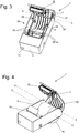
- represents the modular printer according to the invention in the horizontal operating position, with the paper roll compartment opened, ready to load a paper or label roll;
- Fig. 4
- shows the printer of
Fig. 3 , with the paper roll compartment opened and a new paper roll set in place; and - Fig. 5
- shows the printer according to the invention in the vertical operating position, with the paper roll compartment opened and a new paper roll set in place.
- In the following, elements of the printer that are identical from one drawing to the next are identified by the same reference symbols.
-
Figure 1 shows amodular printer 1 according to the invention in a free-standing horizontal operating position resting on a level work surface. Theprinter 1 has a housing 2 withmain walls 3 located (inFigure 1 ) at the top and bottom of the housing 2,sidewalls 4 facing to the right and left, and endwalls 5 facing towards and away from the operator. The rounded contour shapes 10 and 11 follow internal contours of a paper/label roll compartment 30 which will be explained in the context ofFigures 3 and5 . The housing 2 has astationary part 6 and a swing-outhousing part 7 which can be unlocked and swung upward about a hinge axis A-A by reaching with a finger below the finger-pull lever 12 and pulling up on the latter. Anexit slot 8 for the printed receipts orlabels 9 is located at the parting line between thestationary housing part 6 and the swing-outhousing part 7. The word "TEXT" illustrates the position and orientation of the printed information on thelabel 9 as the latter comes out of theslot 8. An on/offswitch 13 in theend wall 5 and a plug-insocket recess 14 in thesidewall 4 are symbolically indicated in the drawing. -
Figure 2 illustrates how thesame printer 1 presents itself in the vertical operating position, attached to adisplay support column 20 of a retail scale. The connection between thesupport column 20 and theprinter 1 is a plug-in connection wherein theprinter 1 is slid with its plug-insocket recess 14 along the carrier arm axis B-B onto a horizontal plug-incarrier arm 21. Thecarrier arm 21 and thesocket recess 14 have mutually conforming keyed profiles, so that theprinter 1 can be mounted on thecarrier arm 21 only in the correct vertical position. Also shown in the drawing is afurther carrier arm 22 for an operator panel or display screen of the retail scale. Thesupport column 20 has a hollow cylindrical profile providing anenclosed passage 23 for power and data cables to theprinter 1 and other units mounted on thesupport column 20. - In the vertical operating position, the
end wall 5 with the on/offswitch 13 is located at the top, while the hinge axis A-A of the swing-outhousing part 7 is located at the bottom of the printer housing. Themain wall 3 with theexit slot 8 faces the operator. As indicated by the word "TEXT", the orientation of the printed information on the ticket orlabel 9 is reversed in comparison toFigure 1 , so that the information is immediately legible as the ticket orlabel 9 moves out of theexit slot 8. -
Figure 3 shows themodular printer 1 according to the invention in the horizontal operating position, with thepaper roll compartment 30 opened, ready to load a paper or label roll. The swing-outhousing part 7 is held in its raised position by a holdinglatch 38. A firstpaper roll cradle 32 is formed in the bottom (relative to the orientation ofFigure 3 ) of thepaper roll compartment 30, i.e. in the area of the roundedoutside contour 10. A width-adjustable paper guide mechanism which allows paper and label rolls of different widths to be used in theprinter 1 is installed in thestationary part 6 of the printer housing 2 with the paper guides 33 flanking the firstpaper roll cradle 32. Athermal printhead 31 and a firstpaper transport roller 34 that is solidly connected to afirst gear 36 are arranged in the fixedhousing part 6 near theexit slot 8, but are not directly visible in the drawing. The firstpaper transport roller 34 is driven by a motor (not visible) which is arranged in thestationary housing part 6. Asecond transport roller 35 with a rotationally connectedsecond gear 37 is arranged on the swing-outhousing part 7. When the swing-outhousing part 7 is closed, thesecond gear 37 is brought into meshing engagement with afirst gear 36, so that the rotary movements of the twotransport rollers -
Figure 4 shows the printer ofFig. 3 with anew paper roll 40 set in place. Theroll 40 is simply laid into thefirst paper cradle 32 with the spooled-off end at the bottom of theroll 40 and directed towards the operator. After the swing-outhousing part 7 has been snapped shut on thestationary housing part 6, theprinter 1 is back in operation. -
Figure 5 shows the modular printer (1) according to the invention in the vertical operating position, with thepaper roll compartment 30 opened and anew paper roll 40 set in place. In comparison toFigure 4 where the printer (1) is in its horizontal operating position, there are some significant differences, namely: - The same width-adjustable paper guide mechanism is installed in the swing-out
part 7 of the printer housing 2 with the paper guides 33 flanking the secondpaper roll cradle 42. - The new paper roll is placed into the second
paper roll cradle 42 which is formed in the swing-outhousing part 7 in the area of the roundedoutside contour 11. - The
roll 40 is laid into thesecond paper cradle 42 with the spooled-off end at the top of theroll 40 and directed towards the operator. - If the text on the label or
ticket 9 is printed in the so-called portrait orientation, i.e. transverse to the transport direction of the paper, the orientation of the printed text on the label orticket 9 is turned 180°. - Except for the relocated paper guide mechanism, all other elements of the
printer 1, for example theprinthead 31 and the tear-off blade 41, stay in the same place when theprinter 1 is converted from a horizontal to a vertical operating position. - Although the invention has been described through the presentation of specific examples, it will be evident to the reader that numerous further variant embodiments could be developed. As an example, the plug-in
carrier arm 21 could be configured so that it could be connected directly to the side of the chassis base of a weighing platform unit, so that the printer would be positioned at the level of the weighing platform unit instead of being elevated on a support column. While the applicants have developed the modular printer with a view to its use with a weighing scale, it should be obvious that the use of the invention is not limited to the weighing field, but that the invention covers any printer that is convertible between a plurality of operating positions in the manner described herein. Also, it should be emphasized that the invention is not limited to the shapes and proportions of the elements shown in the drawings, but that the inventive concept could be fully realized with shapes and proportions different from those shown in the illustrations. -
- 1
- modular printer
- 2
- printer housing
- 3
- main wall
- 4
- side wall
- 5
- end wall
- 6
- fixed housing part
- 7
- hinged swing-out housing part
- 8
- exit slot
- 9
- ticket, label
- 10
- rounded outside contour of first paper roll cradle
- 11
- rounded outside contour of second paper roll cradle
- 12
- finger-pull lever
- 13
- on-off switch/button
- 14
- plug-in socket recess
- 20
- support column
- 21
- plug-in carrier arm for printer
- 22
- plug-in carrier arm for operator panel
- 23
- hollow passage inside support column
- 30
- paper/label roll compartment
- 31
- printhead
- 32
- first paper roll cradle
- 33
- lateral paper guides
- 34
- first paper transport roller
- 35
- second paper transport roller
- 36
- first gear
- 37
- second gear
- 38
- holding latch for hinged swing-out housing part
- 40
- paper/label roll
- 41
- tear-off blade
- 42
- second paper roll cradle
- A-A
- hinge axis of swing-out
housing part 7 - B-B
- longitudinal axis of plug-in
carrier arm 21, plug-in axis - C-C
- axis of rotation of paper/label roll
Claims (11)
- Printer (1) for paper roll and label roll stock (40), comprising a substantially box-shaped housing (2) with main walls (3), side walls (4) and end walls (5), with a fixed housing part (6) and a hinged swing-out housing part (7), a paper/label roll compartment (30) enclosed between the fixed housing part (6) and the swing-out housing part (7), and an exit slot (8) in one of the main walls (3) in the form of a straight-line parting gap separating the fixed housing part (6) and the swing-out housing part (7), and with a printhead (31) arranged in the fixed housing part (6) near the exit slot (8), wherein a hinge axis (A-A) of the swing-out housing part (7) is located in one of the end walls and runs parallel to the axis of rotation (C-C) of the paper- or label roll (40), wherein the printer (1) is designed as a module or building block for use with different weighing scales and checkout systems where the same printer module (1) may be installed on different supporting structures (20) and in different operating positions, specifically in a horizontal operating position where the main wall (3) with the exit slot (8) is facing upward and the end wall containing the hinge axis (A-A) is facing away from the operator, and in a vertical operating position where the main wall (3) with the exit slot (8) is oriented vertically and facing the operator, with the end wall containing the hinge axis (A-A) being located at the bottom of the printer housing (2), wherein in the horizontal operating position, to load a paper- or label roll (40) into the printer (1), the hinged housing part (7) can be tilted upward and away from the operator, allowing the roll (40) to be laid into a first roll cradle (32) that is formed in the bottom of the fixed housing part (6), and wherein in the vertical operating position of the printer (1), the hinged housing part (7) can be tilted forward and towards the operator, allowing the roll (40) to be laid into a second roll cradle (42) that is formed in the swing-out housing part (7) characterized in that the printer (1) further comprising a width-adjustable paper guide mechanism with lateral paper guides (33), where when the printer (1) is set up for the horizontal operating position, the paper guide mechanism is installed in the fixed housing part (6) with the lateral paper guides (33) flanking the first paper roll cradle (32), and when the printer (1) is set up for the vertical operating position, the paper guide mechanism is installed in the swing-out housing part (7) with the lateral paper guides (33) flanking the second roll cradle (42).
- The printer (1) according to claim 1, further comprising a first and a second paper transport roller (34, 35), characterized in that the first paper transport roller (34) is arranged in the fixed housing part (6) near the exit slot and is driven by a roller drive source, and that the second paper transport roller (35) is arranged on the swing-out housing part (7) near the exit slot (8) and is driven by pressure contact engagement with the first paper transport roller (34), as the paper- or label strip moves between the transport rollers (34, 35).
- The printer (1) according to claim 1, further comprising a first and a second paper transport roller (34, 35), characterized in that a first gear (36) which is connected to one end of the first transport roller (34) engages a second gear (37) which is connected to the corresponding end of the second transport roller (35), whereby the rotary movements of the first and second transport rollers (34, 35) are positively locked to each other.
- The printer (1) according to one of the preceding claims, characterized in that the printer (1) is capable of printing in different text orientations so that the printed information can be read in the correct upright orientation already while the ticket or label (9) is moving out of the exit slot (8).
- The printer (1) according to one of the preceding claims, characterized in that the swing-out housing part (7) comprises a snap lock with a finger-pull lever (12), so that the paper roll compartment (30) can be opened by pulling the lever (12) and closed by applying manual pressure to the swing-out housing part (7).
- The printer (1) according to one of the preceding claims, characterized in that the printer (1) is connected to a supporting structure through an electromechanical plug-in connector which secures the printer (1) on the supporting structure and simultaneously provides the electrical connection to deliver power to the printer and transmit data between the printer and another module.
- The printer (1) according to claim 6, characterized in that the electromechanical plug-in connector has the form of a plug-in carrier arm (21) that enters into a corresponding socket recess (14) of the printer (1), wherein the plug-in carrier arm (21) and the socket recess (14) are of a complementary, mutually conforming shape to allow a form-fitting, keyed mechanical plug-in engagement of the plug-in carrier arm (21) in the socket recess (14).
- The printer (1) according to claim 7, characterized in that the supporting structure comprises a substantially vertical support column (20) to which the plug-in carrier arm (21) is attached, standing out horizontally from the support column (20), and that relative to its horizontal longitudinal axis (B-B), the carrier arm (21) is rotationally oriented to hold the modular printer (1) in the vertical operating position.
- The printer (1) according to claim 7, characterized in that the supporting structure comprises the chassis base of a weighing scale, and that the plug-in carrier arm (21) is connected directly to the chassis base, standing out horizontally from the latter, wherein the carrier arm is rotationally oriented to hold the modular printer (1) in the horizontal or a moderately inclined operating position.
- The printer (1) according to one of the claims 1 to 5, characterized in that the printer (1) comprises wall-mounting elements to releasably attach the printer (1) to a wall in the vertical operating position and to provide the power- and data connections to the wall-mounted printer (1).
- The printer (1) according to one of the claims 1 to 5, characterized in that the printer (1) is further operable in a free-standing setup in the horizontal operating position on a counter or table surface, and that the printer (1) is equipped for this purpose with connector plugs for a power cable and a data cable.
Priority Applications (2)
| Application Number | Priority Date | Filing Date | Title |
|---|---|---|---|
| EP14186071.8A EP3001158B1 (en) | 2014-09-24 | 2014-09-24 | Modular printer for roll paper and label stock |
| CN201520741784.3U CN205220072U (en) | 2014-09-24 | 2015-09-23 | Be suitable for printer of spool paper and label certificate |
Applications Claiming Priority (1)
| Application Number | Priority Date | Filing Date | Title |
|---|---|---|---|
| EP14186071.8A EP3001158B1 (en) | 2014-09-24 | 2014-09-24 | Modular printer for roll paper and label stock |
Publications (2)
| Publication Number | Publication Date |
|---|---|
| EP3001158A1 EP3001158A1 (en) | 2016-03-30 |
| EP3001158B1 true EP3001158B1 (en) | 2019-04-10 |
Family
ID=51609989
Family Applications (1)
| Application Number | Title | Priority Date | Filing Date |
|---|---|---|---|
| EP14186071.8A Active EP3001158B1 (en) | 2014-09-24 | 2014-09-24 | Modular printer for roll paper and label stock |
Country Status (2)
| Country | Link |
|---|---|
| EP (1) | EP3001158B1 (en) |
| CN (1) | CN205220072U (en) |
Families Citing this family (6)
| Publication number | Priority date | Publication date | Assignee | Title |
|---|---|---|---|---|
| JP6500633B2 (en) * | 2015-06-24 | 2019-04-17 | カシオ計算機株式会社 | PRINTING APPARATUS, PRINTING METHOD, AND PROGRAM |
| CN110466264A (en) * | 2018-05-10 | 2019-11-19 | 梅特勒-托利多(常州)测量技术有限公司 | Printer for electronic scale |
| CN109016882B (en) * | 2018-07-20 | 2020-11-10 | 深圳市研科数码有限公司 | a receipt printer |
| CN111907224B (en) * | 2020-08-27 | 2024-08-06 | 珠海浩盛标签打印机有限公司 | Hand-held electronic scale printer with front panel uncapped |
| CN113571367B (en) * | 2021-08-04 | 2024-04-12 | 杭州恒汇智能装备有限公司 | Intelligent cloud box with multistage feedback keys |
| CN114987066B (en) * | 2022-07-06 | 2023-07-18 | 时时同云科技(成都)有限责任公司 | Printer and cashier device |
Family Cites Families (4)
| Publication number | Priority date | Publication date | Assignee | Title |
|---|---|---|---|---|
| JP3797622B2 (en) * | 2004-01-28 | 2006-07-19 | 東芝テック株式会社 | Payment terminal |
| US7306386B2 (en) * | 2004-07-29 | 2007-12-11 | Zih Corp. | Docking station and associated method for docking a portable printer |
| US7578628B2 (en) * | 2005-05-27 | 2009-08-25 | Intermec Ip Corp. | Portable electronic device including coupling member with electrical supply contacts |
| USD574427S1 (en) | 2006-09-20 | 2008-08-05 | Mettler-Toledo Ag | Printer |
-
2014
- 2014-09-24 EP EP14186071.8A patent/EP3001158B1/en active Active
-
2015
- 2015-09-23 CN CN201520741784.3U patent/CN205220072U/en not_active Expired - Lifetime
Non-Patent Citations (1)
| Title |
|---|
| None * |
Also Published As
| Publication number | Publication date |
|---|---|
| CN205220072U (en) | 2016-05-11 |
| EP3001158A1 (en) | 2016-03-30 |
Similar Documents
| Publication | Publication Date | Title |
|---|---|---|
| EP3001158A1 (en) | Modular printer for roll paper and label stock | |
| CZ101294A3 (en) | Printing apparatus | |
| CN209625354U (en) | Sales data processing device | |
| JPH0821129B2 (en) | Product grasping device for shops | |
| EP3680109B1 (en) | Printer | |
| CN205553595U (en) | Printer that with weigh balance be used together is connected with direct data transmission | |
| EP3666537A1 (en) | Printer and printer display device | |
| JP5379837B2 (en) | Electronics | |
| JP6191310B2 (en) | Printing apparatus and sales data processing apparatus having the printing apparatus | |
| JP7010533B2 (en) | Product registration device and POS device | |
| US7268793B2 (en) | Device for arraying a thermal printer head for use in a thermal printer | |
| JPH065182Y2 (en) | Weighing and pricing device | |
| CN102982622A (en) | Electronic device | |
| JP2011230330A (en) | Printer stand | |
| JP3739995B2 (en) | Printer | |
| JP2500897B2 (en) | Electronic charge balance | |
| US6126340A (en) | Printer | |
| CN106915164A (en) | Recording sheet storage device, electronic equipment and electronic cash register | |
| EP3015272B1 (en) | Thermal printer module | |
| JP2017120520A (en) | POS system and registration counter | |
| JPH115333A (en) | Label and receipt issuing printer | |
| JP6974105B2 (en) | Product sales data processing equipment and programs | |
| US20050089357A1 (en) | Printing module for mounting in shop scales | |
| JP2006092459A (en) | Product sales data processing device | |
| WO1998021040A1 (en) | Printer |
Legal Events
| Date | Code | Title | Description |
|---|---|---|---|
| PUAI | Public reference made under article 153(3) epc to a published international application that has entered the european phase |
Free format text: ORIGINAL CODE: 0009012 |
|
| AK | Designated contracting states |
Kind code of ref document: A1 Designated state(s): AL AT BE BG CH CY CZ DE DK EE ES FI FR GB GR HR HU IE IS IT LI LT LU LV MC MK MT NL NO PL PT RO RS SE SI SK SM TR |
|
| AX | Request for extension of the european patent |
Extension state: BA ME |
|
| 17P | Request for examination filed |
Effective date: 20160923 |
|
| RBV | Designated contracting states (corrected) |
Designated state(s): AL AT BE BG CH CY CZ DE DK EE ES FI FR GB GR HR HU IE IS IT LI LT LU LV MC MK MT NL NO PL PT RO RS SE SI SK SM TR |
|
| STAA | Information on the status of an ep patent application or granted ep patent |
Free format text: STATUS: EXAMINATION IS IN PROGRESS |
|
| 17Q | First examination report despatched |
Effective date: 20170824 |
|
| RIC1 | Information provided on ipc code assigned before grant |
Ipc: G07G 5/00 20060101ALI20180905BHEP Ipc: G07G 1/00 20060101ALI20180905BHEP Ipc: G01G 19/414 20060101AFI20180905BHEP Ipc: B41J 3/36 20060101ALI20180905BHEP Ipc: B41J 3/407 20060101ALI20180905BHEP Ipc: G01G 23/42 20060101ALI20180905BHEP Ipc: B41J 15/04 20060101ALI20180905BHEP |
|
| GRAP | Despatch of communication of intention to grant a patent |
Free format text: ORIGINAL CODE: EPIDOSNIGR1 |
|
| STAA | Information on the status of an ep patent application or granted ep patent |
Free format text: STATUS: GRANT OF PATENT IS INTENDED |
|
| INTG | Intention to grant announced |
Effective date: 20181105 |
|
| GRAS | Grant fee paid |
Free format text: ORIGINAL CODE: EPIDOSNIGR3 |
|
| GRAA | (expected) grant |
Free format text: ORIGINAL CODE: 0009210 |
|
| STAA | Information on the status of an ep patent application or granted ep patent |
Free format text: STATUS: THE PATENT HAS BEEN GRANTED |
|
| AK | Designated contracting states |
Kind code of ref document: B1 Designated state(s): AL AT BE BG CH CY CZ DE DK EE ES FI FR GB GR HR HU IE IS IT LI LT LU LV MC MK MT NL NO PL PT RO RS SE SI SK SM TR |
|
| REG | Reference to a national code |
Ref country code: GB Ref legal event code: FG4D |
|
| REG | Reference to a national code |
Ref country code: CH Ref legal event code: EP Ref country code: AT Ref legal event code: REF Ref document number: 1119327 Country of ref document: AT Kind code of ref document: T Effective date: 20190415 |
|
| REG | Reference to a national code |
Ref country code: IE Ref legal event code: FG4D |
|
| REG | Reference to a national code |
Ref country code: DE Ref legal event code: R096 Ref document number: 602014044336 Country of ref document: DE |
|
| REG | Reference to a national code |
Ref country code: NL Ref legal event code: MP Effective date: 20190410 |
|
| REG | Reference to a national code |
Ref country code: LT Ref legal event code: MG4D |
|
| REG | Reference to a national code |
Ref country code: AT Ref legal event code: MK05 Ref document number: 1119327 Country of ref document: AT Kind code of ref document: T Effective date: 20190410 |
|
| PG25 | Lapsed in a contracting state [announced via postgrant information from national office to epo] |
Ref country code: NL Free format text: LAPSE BECAUSE OF FAILURE TO SUBMIT A TRANSLATION OF THE DESCRIPTION OR TO PAY THE FEE WITHIN THE PRESCRIBED TIME-LIMIT Effective date: 20190410 |
|
| PG25 | Lapsed in a contracting state [announced via postgrant information from national office to epo] |
Ref country code: PT Free format text: LAPSE BECAUSE OF FAILURE TO SUBMIT A TRANSLATION OF THE DESCRIPTION OR TO PAY THE FEE WITHIN THE PRESCRIBED TIME-LIMIT Effective date: 20190910 Ref country code: LT Free format text: LAPSE BECAUSE OF FAILURE TO SUBMIT A TRANSLATION OF THE DESCRIPTION OR TO PAY THE FEE WITHIN THE PRESCRIBED TIME-LIMIT Effective date: 20190410 Ref country code: NO Free format text: LAPSE BECAUSE OF FAILURE TO SUBMIT A TRANSLATION OF THE DESCRIPTION OR TO PAY THE FEE WITHIN THE PRESCRIBED TIME-LIMIT Effective date: 20190710 Ref country code: FI Free format text: LAPSE BECAUSE OF FAILURE TO SUBMIT A TRANSLATION OF THE DESCRIPTION OR TO PAY THE FEE WITHIN THE PRESCRIBED TIME-LIMIT Effective date: 20190410 Ref country code: SE Free format text: LAPSE BECAUSE OF FAILURE TO SUBMIT A TRANSLATION OF THE DESCRIPTION OR TO PAY THE FEE WITHIN THE PRESCRIBED TIME-LIMIT Effective date: 20190410 Ref country code: AL Free format text: LAPSE BECAUSE OF FAILURE TO SUBMIT A TRANSLATION OF THE DESCRIPTION OR TO PAY THE FEE WITHIN THE PRESCRIBED TIME-LIMIT Effective date: 20190410 Ref country code: ES Free format text: LAPSE BECAUSE OF FAILURE TO SUBMIT A TRANSLATION OF THE DESCRIPTION OR TO PAY THE FEE WITHIN THE PRESCRIBED TIME-LIMIT Effective date: 20190410 Ref country code: HR Free format text: LAPSE BECAUSE OF FAILURE TO SUBMIT A TRANSLATION OF THE DESCRIPTION OR TO PAY THE FEE WITHIN THE PRESCRIBED TIME-LIMIT Effective date: 20190410 |
|
| PG25 | Lapsed in a contracting state [announced via postgrant information from national office to epo] |
Ref country code: BG Free format text: LAPSE BECAUSE OF FAILURE TO SUBMIT A TRANSLATION OF THE DESCRIPTION OR TO PAY THE FEE WITHIN THE PRESCRIBED TIME-LIMIT Effective date: 20190710 Ref country code: GR Free format text: LAPSE BECAUSE OF FAILURE TO SUBMIT A TRANSLATION OF THE DESCRIPTION OR TO PAY THE FEE WITHIN THE PRESCRIBED TIME-LIMIT Effective date: 20190711 Ref country code: LV Free format text: LAPSE BECAUSE OF FAILURE TO SUBMIT A TRANSLATION OF THE DESCRIPTION OR TO PAY THE FEE WITHIN THE PRESCRIBED TIME-LIMIT Effective date: 20190410 Ref country code: PL Free format text: LAPSE BECAUSE OF FAILURE TO SUBMIT A TRANSLATION OF THE DESCRIPTION OR TO PAY THE FEE WITHIN THE PRESCRIBED TIME-LIMIT Effective date: 20190410 Ref country code: RS Free format text: LAPSE BECAUSE OF FAILURE TO SUBMIT A TRANSLATION OF THE DESCRIPTION OR TO PAY THE FEE WITHIN THE PRESCRIBED TIME-LIMIT Effective date: 20190410 |
|
| PG25 | Lapsed in a contracting state [announced via postgrant information from national office to epo] |
Ref country code: AT Free format text: LAPSE BECAUSE OF FAILURE TO SUBMIT A TRANSLATION OF THE DESCRIPTION OR TO PAY THE FEE WITHIN THE PRESCRIBED TIME-LIMIT Effective date: 20190410 Ref country code: IS Free format text: LAPSE BECAUSE OF FAILURE TO SUBMIT A TRANSLATION OF THE DESCRIPTION OR TO PAY THE FEE WITHIN THE PRESCRIBED TIME-LIMIT Effective date: 20190810 |
|
| REG | Reference to a national code |
Ref country code: DE Ref legal event code: R097 Ref document number: 602014044336 Country of ref document: DE |
|
| PG25 | Lapsed in a contracting state [announced via postgrant information from national office to epo] |
Ref country code: EE Free format text: LAPSE BECAUSE OF FAILURE TO SUBMIT A TRANSLATION OF THE DESCRIPTION OR TO PAY THE FEE WITHIN THE PRESCRIBED TIME-LIMIT Effective date: 20190410 Ref country code: DK Free format text: LAPSE BECAUSE OF FAILURE TO SUBMIT A TRANSLATION OF THE DESCRIPTION OR TO PAY THE FEE WITHIN THE PRESCRIBED TIME-LIMIT Effective date: 20190410 Ref country code: RO Free format text: LAPSE BECAUSE OF FAILURE TO SUBMIT A TRANSLATION OF THE DESCRIPTION OR TO PAY THE FEE WITHIN THE PRESCRIBED TIME-LIMIT Effective date: 20190410 Ref country code: CZ Free format text: LAPSE BECAUSE OF FAILURE TO SUBMIT A TRANSLATION OF THE DESCRIPTION OR TO PAY THE FEE WITHIN THE PRESCRIBED TIME-LIMIT Effective date: 20190410 Ref country code: SK Free format text: LAPSE BECAUSE OF FAILURE TO SUBMIT A TRANSLATION OF THE DESCRIPTION OR TO PAY THE FEE WITHIN THE PRESCRIBED TIME-LIMIT Effective date: 20190410 |
|
| PLBE | No opposition filed within time limit |
Free format text: ORIGINAL CODE: 0009261 |
|
| STAA | Information on the status of an ep patent application or granted ep patent |
Free format text: STATUS: NO OPPOSITION FILED WITHIN TIME LIMIT |
|
| PG25 | Lapsed in a contracting state [announced via postgrant information from national office to epo] |
Ref country code: SM Free format text: LAPSE BECAUSE OF FAILURE TO SUBMIT A TRANSLATION OF THE DESCRIPTION OR TO PAY THE FEE WITHIN THE PRESCRIBED TIME-LIMIT Effective date: 20190410 Ref country code: IT Free format text: LAPSE BECAUSE OF FAILURE TO SUBMIT A TRANSLATION OF THE DESCRIPTION OR TO PAY THE FEE WITHIN THE PRESCRIBED TIME-LIMIT Effective date: 20190410 |
|
| 26N | No opposition filed |
Effective date: 20200113 |
|
| PG25 | Lapsed in a contracting state [announced via postgrant information from national office to epo] |
Ref country code: TR Free format text: LAPSE BECAUSE OF FAILURE TO SUBMIT A TRANSLATION OF THE DESCRIPTION OR TO PAY THE FEE WITHIN THE PRESCRIBED TIME-LIMIT Effective date: 20190410 |
|
| PG25 | Lapsed in a contracting state [announced via postgrant information from national office to epo] |
Ref country code: SI Free format text: LAPSE BECAUSE OF FAILURE TO SUBMIT A TRANSLATION OF THE DESCRIPTION OR TO PAY THE FEE WITHIN THE PRESCRIBED TIME-LIMIT Effective date: 20190410 Ref country code: MC Free format text: LAPSE BECAUSE OF FAILURE TO SUBMIT A TRANSLATION OF THE DESCRIPTION OR TO PAY THE FEE WITHIN THE PRESCRIBED TIME-LIMIT Effective date: 20190410 |
|
| PG25 | Lapsed in a contracting state [announced via postgrant information from national office to epo] |
Ref country code: IE Free format text: LAPSE BECAUSE OF NON-PAYMENT OF DUE FEES Effective date: 20190924 Ref country code: LU Free format text: LAPSE BECAUSE OF NON-PAYMENT OF DUE FEES Effective date: 20190924 |
|
| REG | Reference to a national code |
Ref country code: BE Ref legal event code: MM Effective date: 20190930 |
|
| PG25 | Lapsed in a contracting state [announced via postgrant information from national office to epo] |
Ref country code: BE Free format text: LAPSE BECAUSE OF NON-PAYMENT OF DUE FEES Effective date: 20190930 |
|
| GBPC | Gb: european patent ceased through non-payment of renewal fee |
Effective date: 20190924 |
|
| PG25 | Lapsed in a contracting state [announced via postgrant information from national office to epo] |
Ref country code: GB Free format text: LAPSE BECAUSE OF NON-PAYMENT OF DUE FEES Effective date: 20190924 |
|
| PG25 | Lapsed in a contracting state [announced via postgrant information from national office to epo] |
Ref country code: CY Free format text: LAPSE BECAUSE OF FAILURE TO SUBMIT A TRANSLATION OF THE DESCRIPTION OR TO PAY THE FEE WITHIN THE PRESCRIBED TIME-LIMIT Effective date: 20190410 |
|
| PG25 | Lapsed in a contracting state [announced via postgrant information from national office to epo] |
Ref country code: HU Free format text: LAPSE BECAUSE OF FAILURE TO SUBMIT A TRANSLATION OF THE DESCRIPTION OR TO PAY THE FEE WITHIN THE PRESCRIBED TIME-LIMIT; INVALID AB INITIO Effective date: 20140924 Ref country code: MT Free format text: LAPSE BECAUSE OF FAILURE TO SUBMIT A TRANSLATION OF THE DESCRIPTION OR TO PAY THE FEE WITHIN THE PRESCRIBED TIME-LIMIT Effective date: 20190410 |
|
| PG25 | Lapsed in a contracting state [announced via postgrant information from national office to epo] |
Ref country code: MK Free format text: LAPSE BECAUSE OF FAILURE TO SUBMIT A TRANSLATION OF THE DESCRIPTION OR TO PAY THE FEE WITHIN THE PRESCRIBED TIME-LIMIT Effective date: 20190410 |
|
| REG | Reference to a national code |
Ref country code: CH Ref legal event code: U11 Free format text: ST27 STATUS EVENT CODE: U-0-0-U10-U11 (AS PROVIDED BY THE NATIONAL OFFICE) Effective date: 20251001 |
|
| PGFP | Annual fee paid to national office [announced via postgrant information from national office to epo] |
Ref country code: DE Payment date: 20250926 Year of fee payment: 12 |
|
| PGFP | Annual fee paid to national office [announced via postgrant information from national office to epo] |
Ref country code: FR Payment date: 20250925 Year of fee payment: 12 |
|
| PGFP | Annual fee paid to national office [announced via postgrant information from national office to epo] |
Ref country code: CH Payment date: 20251001 Year of fee payment: 12 |