EP3001048A1 - Journal air bearing with air-film-supply vent - Google Patents
Journal air bearing with air-film-supply vent Download PDFInfo
- Publication number
- EP3001048A1 EP3001048A1 EP15186927.8A EP15186927A EP3001048A1 EP 3001048 A1 EP3001048 A1 EP 3001048A1 EP 15186927 A EP15186927 A EP 15186927A EP 3001048 A1 EP3001048 A1 EP 3001048A1
- Authority
- EP
- European Patent Office
- Prior art keywords
- foil
- shaft
- journal
- air
- bearing
- Prior art date
- Legal status (The legal status is an assumption and is not a legal conclusion. Google has not performed a legal analysis and makes no representation as to the accuracy of the status listed.)
- Granted
Links
Images
Classifications
-
- F—MECHANICAL ENGINEERING; LIGHTING; HEATING; WEAPONS; BLASTING
- F16—ENGINEERING ELEMENTS AND UNITS; GENERAL MEASURES FOR PRODUCING AND MAINTAINING EFFECTIVE FUNCTIONING OF MACHINES OR INSTALLATIONS; THERMAL INSULATION IN GENERAL
- F16C—SHAFTS; FLEXIBLE SHAFTS; ELEMENTS OR CRANKSHAFT MECHANISMS; ROTARY BODIES OTHER THAN GEARING ELEMENTS; BEARINGS
- F16C17/00—Sliding-contact bearings for exclusively rotary movement
- F16C17/02—Sliding-contact bearings for exclusively rotary movement for radial load only
- F16C17/024—Sliding-contact bearings for exclusively rotary movement for radial load only with flexible leaves to create hydrodynamic wedge, e.g. radial foil bearings
-
- F—MECHANICAL ENGINEERING; LIGHTING; HEATING; WEAPONS; BLASTING
- F16—ENGINEERING ELEMENTS AND UNITS; GENERAL MEASURES FOR PRODUCING AND MAINTAINING EFFECTIVE FUNCTIONING OF MACHINES OR INSTALLATIONS; THERMAL INSULATION IN GENERAL
- F16C—SHAFTS; FLEXIBLE SHAFTS; ELEMENTS OR CRANKSHAFT MECHANISMS; ROTARY BODIES OTHER THAN GEARING ELEMENTS; BEARINGS
- F16C37/00—Cooling of bearings
- F16C37/002—Cooling of bearings of fluid bearings
-
- F—MECHANICAL ENGINEERING; LIGHTING; HEATING; WEAPONS; BLASTING
- F16—ENGINEERING ELEMENTS AND UNITS; GENERAL MEASURES FOR PRODUCING AND MAINTAINING EFFECTIVE FUNCTIONING OF MACHINES OR INSTALLATIONS; THERMAL INSULATION IN GENERAL
- F16C—SHAFTS; FLEXIBLE SHAFTS; ELEMENTS OR CRANKSHAFT MECHANISMS; ROTARY BODIES OTHER THAN GEARING ELEMENTS; BEARINGS
- F16C2326/00—Articles relating to transporting
- F16C2326/43—Aeroplanes; Helicopters
-
- F—MECHANICAL ENGINEERING; LIGHTING; HEATING; WEAPONS; BLASTING
- F16—ENGINEERING ELEMENTS AND UNITS; GENERAL MEASURES FOR PRODUCING AND MAINTAINING EFFECTIVE FUNCTIONING OF MACHINES OR INSTALLATIONS; THERMAL INSULATION IN GENERAL
- F16C—SHAFTS; FLEXIBLE SHAFTS; ELEMENTS OR CRANKSHAFT MECHANISMS; ROTARY BODIES OTHER THAN GEARING ELEMENTS; BEARINGS
- F16C43/00—Assembling bearings
- F16C43/02—Assembling sliding-contact bearings
Definitions
- This invention relates, generally, to a journal air bearing (hydrodynamic fluid film journal bearing or foil bearing) and, more specifically, to such a bearing used in an Air Management System (AMS) rotating machinery.
- AMS Air Management System
- a journal air bearing supports a rotatable component, such as a shaft disposed within an air-cycle machine of an aircraft.
- a typical arrangement of such a bearing includes a top foil, an intermediate foil, and a bump foil. The foils are received within a journal sleeve and wrapped around the component. The top foil is disposed closer to the component than is each of the other foils.
- the bearing uses a fluid, such as air, to support the component during its rotation. There is little or no contact between the top foil and component when it rotates.
- the bearing may include also a formed key that extends radially relative to an axis of rotation of the component.
- the key is received within a slot or keyway defined in the sleeve and contacts edges defined by the slot to limit rotation of the foils relative to the component.
- the air communicates through a clearance provided at the key and is pressurized during the rotation.
- the bearing acts as a pump that draws in ambient air axially along the keyway and then through viscous-shear drives that drive the air circumferentially around the bearing, creating a highpressure pocket or air film to react to radial loads.
- the air film defines an entrance or a supply area.
- the pressure varies depending upon a circumferential location thereof relative to the keyway, such varied pressure being able to destabilize the component.
- the pressure can typically peak at about 180° from the key.
- a journal air bearing for a rotatable shaft of an air cycle machine includes a top foil configured to receive the shaft, an intermediate foil disposed radially outboard the top foil, and a journal sleeve disposed radially outboard the intermediate foil.
- the intermediate foil defines a row of a plurality of holes configured to act as a vent to communicate fluid to an increased supply area of a fluid film.
- the row of holes of the intermediate foil provides a third path for the fluid to enter the fluid film, resulting in an increase in the supply area.
- the bearing provides increased capacity through the increase in the supply area of the fluid film, which results in lower entrance losses and a more efficient pumping action for viscous shear that produces the fluid film.
- a non-limiting exemplary embodiment of a hydrodynamic fluid film journal air bearing is generally indicated at 10.
- the bearing 10 is disclosed herein as being implemented with AMS rotating machinery (more specifically, a rotatable component, such as a shaft, disposed within an air-cycle machine of an aircraft), it should be appreciated that the bearing can be implemented with other aircraft accessories (such as turbo-compressors, cabin air compressors, or ram air fans).
- the bearing 10 includes a top foil 12 , an intermediate foil 14 , and a bump foil 16 and rotatably supports a rotatable component-namely, a shaft 18 -of an air-cycle machine 20.
- a rotatable component namely, a shaft 18 -of an air-cycle machine 20.
- Each of the top, intermediate, and bump foils 12, 14, 16 defines a tab and free end.
- the shaft 18 is positioned inside the bearing 10 and typically rotates clockwise with respect to the view of the bearing 10 shown in FIG. 2 .
- the bearing 10 and shaft 18 are received within a journal sleeve 22 formed as a unitary body that defines outer and inner diameter surfaces 24, 26 and, in turn, is received within a bore 28 of a housing 30.
- the sleeve 22 is arranged about a central rotational axis " A ,” and O-rings 32 are used to retain the sleeve 22 positioned within the bore 28.
- the sleeve 22 can be conventionally cylindrical or shaped with any suitable profile, made of a metallic material, and shaped using known techniques-such as milling, turning, and grinding. It should be noted also that the O-rings 32 can be of a conventional type known for use with hydrodynamic fluid film journal bearings.
- the foils 12, 14, 16 are arranged inside the sleeve 22.
- Each of the foils 12, 14, 16 is a thin sheet of material (e.g., nickel-based alloys or steel) wrapped or rolled in a generally cylindrical shape and positioned in a bore of the sleeve 22.
- the bump foil 16 is corrugated, allowing a working or cooling fluid-such as air-to flow through spaces formed between adjacent corrugations.
- the bump foil 16 is also positioned adjacent to the inner diameter surface 26 of the sleeve 12 and defines a bent end 34 that can be angled at approximately 90° with respect to an adjacent, generally cylindrical portion of the bump foil 16 .
- a formed key 36 extends radially relative to the shaft 18 and is received within a key slot (or keyway) 38 defined within the sleeve 22. More specifically, the slot 38 extends entirely through a wall defined between the outer and inner diameter surfaces 24, 26 of the sleeve 22. The slot 38 also is elongated and rectangular and arranged generally parallel to the axis " A* .” The slot 38 also defines a first end that is spaced from a first end of the sleeve 22 a distance and second end that is spaced from a second end of the sleeve 22 a distance.
- one distance is greater than the other such that the slot 38 is axially (or longitudinally) offset with respect to a length of the sleeve 22.
- the slot 38 can be offset in this manner for fool-proofing purposes during assembly of the bearing 10.
- the slot 38 can be axially centered relative to the sleeve 22.
- the bent end 34 of the bump foil 16 extends radially outward at least partially into the slot 38 to engage the slot 38 and retain the bump foil 16 relative to the sleeve 22.
- the top, intermediate, and bump foils 12, 14, 16 are wrapped about or around the shaft 36. More specifically, the top foil 12 is positioned radially outboard the shaft 18 and adjacent to and radially inboard the intermediate foil 14, and the intermediate foil 14 is positioned adjacent to and radially inboard the bump foil 16.
- the bump foil 16 is disposed radially outboard the top and intermediate foils 12, 14 and biases the intermediate foil 14 toward the top foil 12 to hold respective positions of the top and intermediate foils 12, 14 relative to the shaft 18.
- top and intermediate foils 12, 14 are joined together at a bent region 40 that extends radially outward at least partially into the slot 38 to engage the slot 38 and retain both the top and intermediate foils 12, 14 relative to the sleeve 22.
- the bent region 40 can be angled at approximately 90° with respect to corresponding adjacent, generally cylindrical portions of the top and intermediate foils 12, 14.
- the top and intermediate foils 12, 14 are formed by opposite first and second end portions 42, 44 of a single integral piece or sheet that join at the bent region 40, which is located in a middle portion of the sheet.
- the top and intermediate foils 12, 14 are formed from separate sheets connected together at the bent region 40 using welding, brazing, or other suitable attachment means.
- the key 36 joins the top and intermediate foils 12, 14 with each other.
- the air is communicated through channels 46 defined between the intermediate and bump foils 14, 16 and channels 48 defined between the bump foil 16 and sleeve 22.
- the air removes thermal energy from the bearing 10.
- the air is communicated also to an area defined between the top foil 12 and shaft 18 through a gap 50. More specifically, the shaft 18 rotates when the machine 20 operates. Rotation of the shaft 18 causes the air to form a cushion (often referred to as an "air bearing” or “air film") 52 that supports the shaft 18 while rotating at operating speed. In particular, the rotation causes the air to pressurize in areas between the top foil 12 and shaft 18, urging the top foil 12 radially away from the shaft 18. The shaft 18 then rotates as the shaft 18 is supported by the pressurized air. There is little or no contact between the top foil 12 and shaft 18 when the shaft 18 is rotating at an operational speed of the shaft 18. However, contact between the top foil 12 and shaft 18 may still occur at relatively low operational speed, such as during start-up and shutdown phases, and due to incidental contact during regular operation of the machine 20.
- the shaft 18 rotates into a wedge area on a vent side.
- a form radius of the foil 12, 14, 16 is, for example, about 0.020" (0.508 mm) on the vent side, which is less than or approximately equal to half of a form radius of the foil 12 , 14, 16 on the opposite side, which is about 0.040" (1.016 mm).
- the foil 12 , 14, 16 on the vent side is lower (near to an edge of the slot 38) than is the foil 12, 14, 16 on the opposite side. In this way, the hydrodynamic air film 52 is generated.
- the shaft 18 is shown rotating counter-clockwise. The rotation is into a free end of each of the top and bump foils 12, 16 located on a same side of the key 36 within the sleeve 22.
- a row of a plurality of holes 54 is defined in the intermediate foil 14 and configured to act as a vent to communicate the air to an increased supply area to the air film 52.
- the holes 54 are located on the same side of the key 36 as the respective free ends of the top and bump foils 12, 16 .
- the row of holes 54 is slightly offset with the key 36.
- a radially inner surface of the top foil 12 exposed to the shaft 18 is coated with a suitable dry film lubricant. Use of such lubricant can reduce friction caused by the shaft 18 when the shaft 18 is accelerating to operating speed, decelerating from the operating speed, stopped, and/or subject to incidental contact with the top foil 12 during regular operation of the machine 20.
- the holes 54 provide a path for communicating the air from between the top and intermediate foils 12, 14 and the intermediate and bump foils 12, 14. Allowing the air to communicate in this manner provides increased capacity to the bearing 10 through an increased supply area to the air film 52, which results in lower entrance losses and a more efficient pumping action for viscous shear that produces the air film 52.
- a communication path provided by the holes 54 is slightly offset with the key 36 to facilitate communication of the air to the supply area to the air film 52.
- the row of holes 54 extends from one edge of the intermediate foil 14 to the other edge. In another version, the row extends only partially from the one edge to the other edge.
- the row of holes 54 is parallel with the axis " A " of the shaft 18, the holes 54 are linearly spaced from each other, and end holes 54 are spaced from the respective edges of the intermediate foil 14 .
- the row of holes 54 is not parallel with the axis " A " and/or linear.
- Other types of aperture 54 such as a slot, may be used to provide the communication path to the supply area to the air film 52.
- Each of the holes 54 defines a diameter of the hole 54.
- the diameters are equal to each other.
- the diameter is about 0.020 +/- about 0.002 inch (about 0.508 +/- about 0.0508 mm).
- the diameters are different than each other.
- some of the diameters are equal to each other while others are different than those and equal to each other.
- some of the diameters are equal to each other while others are different than those and each other.
- the row of holes 54 of the intermediate foil 14 provides a third path for the air to enter the air film 52, resulting in an increase in the supply area.
- the bearing 10 provides increased capacity through the increase in the supply area to the air film 52, which results in lower entrance losses and a more efficient pumping action for viscous shear that produces the air film 52.
- Another way to improve the capacity of the bearing 10 is to increase stiffness of the top foil 12 such that deformation of the top foil 12 is reduced relative to thickness of the air film 52. Otherwise, the deformation-which can be approximately equal to the thickness of the air film 52 -allows peak pressure of the air film 52 to vent down valleys defined between respective adjacent lines of contact of the bump foil 16, which limits capacity of the bearing 10.
- thickness of the top foil 12 is about 0.003" (0.076 mm) to about 0.004" (0.102 mm)
- pitch of the bump foil 16 is about 0.186" (4.724 mm) to about 0.136" (3.454 mm), greatly reducing the deformation.
- Another way to improve the capacity of the bearing 10 is to reduce finish for a coating or surface of the top foil 12 .
- the thickness of the air film 52 is on the order of roughness of the surface.
- the allowable maximum of the surface finish of the top foil 12 is about 12 Ra
- the surface finish of the shaft 18 is about 4 Ra.
- Another way to improve the capacity of the bearing 10 is to reduce variation in thickness of the intermediate foil 14. Coating of the intermediate foil 14 is eliminated to reduce the thickness variation of the intermediate foil 14 that would otherwise exist due to the coating, which would translate into "load deflection" variation. In a version of the embodiment, the coating of the intermediate foil 14 is eliminated so that the total thickness variation is about 0.0008" (0.02032 mm). This has an added benefit of increasing damping of the bearing 10 by increasing a coefficient of friction between the top and intermediate foils 12, 14, leading to more "Coulomb” damping and reduction of ACM sub-synchronous response.
- Another way to improve the capacity of the bearing 10 is to reduce pre-load of the bearing 10. Tighter (smaller) load deflections result in reduced capacity of the bearing 10. In a version of the embodiment, for an applied load of about +/- 12 lbs. (5.448 kg), the allowable deflection is about 0.003" (0.076 mm) to about 0.004" (0.102 mm).
- Another way to improve the capacity of the bearing 10 is to increase a projected area of the bearing 10 to a length-to-diameter ratio of about 2.0.
- a width of the top foil 12 is about 1.717" (4.361 cm).
- any anti-skewing tabs are flat.
- U.S. Patent 7,648,279 discusses anti-skewing tabs of a hydrodynamic fluid film journal air bearing (such discussion and corresponding figures of the patent being incorporated herein by reference). This flatness eliminates any potential local hard spots and allows for a more robust design for handling.
Landscapes
- Engineering & Computer Science (AREA)
- General Engineering & Computer Science (AREA)
- Mechanical Engineering (AREA)
- Physics & Mathematics (AREA)
- Fluid Mechanics (AREA)
- Support Of The Bearing (AREA)
Abstract
Description
- This invention relates, generally, to a journal air bearing (hydrodynamic fluid film journal bearing or foil bearing) and, more specifically, to such a bearing used in an Air Management System (AMS) rotating machinery.
- As known, a journal air bearing supports a rotatable component, such as a shaft disposed within an air-cycle machine of an aircraft. A typical arrangement of such a bearing includes a top foil, an intermediate foil, and a bump foil. The foils are received within a journal sleeve and wrapped around the component. The top foil is disposed closer to the component than is each of the other foils. The bearing uses a fluid, such as air, to support the component during its rotation. There is little or no contact between the top foil and component when it rotates.
- The bearing may include also a formed key that extends radially relative to an axis of rotation of the component. The key is received within a slot or keyway defined in the sleeve and contacts edges defined by the slot to limit rotation of the foils relative to the component. The air communicates through a clearance provided at the key and is pressurized during the rotation. The bearing acts as a pump that draws in ambient air axially along the keyway and then through viscous-shear drives that drive the air circumferentially around the bearing, creating a highpressure pocket or air film to react to radial loads. The air film defines an entrance or a supply area. The pressure varies depending upon a circumferential location thereof relative to the keyway, such varied pressure being able to destabilize the component. The pressure can typically peak at about 180° from the key.
- It is desirable to provide increased capacity to the bearing through an increased supply area to the air film, which results in lower entrance losses and a more efficient pumping action for viscous shear that produces the air film.
- According to a non-limiting exemplary embodiment of the invention, a journal air bearing for a rotatable shaft of an air cycle machine is provided. The bearing includes a top foil configured to receive the shaft, an intermediate foil disposed radially outboard the top foil, and a journal sleeve disposed radially outboard the intermediate foil. The intermediate foil defines a row of a plurality of holes configured to act as a vent to communicate fluid to an increased supply area of a fluid film.
- The row of holes of the intermediate foil provides a third path for the fluid to enter the fluid film, resulting in an increase in the supply area. The bearing provides increased capacity through the increase in the supply area of the fluid film, which results in lower entrance losses and a more efficient pumping action for viscous shear that produces the fluid film.
- The subject matter that is regarded as the invention is particularly pointed out and distinctly claimed in the claims at the conclusion of the specification. The foregoing and other features and advantages of the invention are apparent from the following detailed description taken in conjunction with the accompanying drawings in which:
-
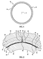
FIG. 1 is an end view of a non-limiting exemplary embodiment of a journal air bearing according to the present invention; -
FIG. 2 is a partial environmental view of the embodiment of the journal air bearing illustrated inFIG. 1 supporting a rotatable shaft of an air-cycle machine; -
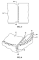
FIG. 3 is an elevated view of an intermediate foil of the embodiment of the journal air bearing illustrated inFIG. 1 in an unwrapped state; and -
FIG. 4 is a perspective view of the embodiment of the journal air bearing illustrated inFIG. 1 showing the shaft rotating counter-clockwise. - Referring now to
FIG. 1 , a non-limiting exemplary embodiment of a hydrodynamic fluid film journal air bearing is generally indicated at 10. Although thebearing 10 is disclosed herein as being implemented with AMS rotating machinery (more specifically, a rotatable component, such as a shaft, disposed within an air-cycle machine of an aircraft), it should be appreciated that the bearing can be implemented with other aircraft accessories (such as turbo-compressors, cabin air compressors, or ram air fans). - As shown in
FIGS. 1 and 2 , thebearing 10 includes atop foil 12, anintermediate foil 14, and abump foil 16 and rotatably supports a rotatable component-namely, a shaft 18-of an air-cycle machine 20. Each of the top, intermediate, andbump foils shaft 18 is positioned inside thebearing 10 and typically rotates clockwise with respect to the view of thebearing 10 shown inFIG. 2 . The bearing 10 andshaft 18 are received within ajournal sleeve 22 formed as a unitary body that defines outer andinner diameter surfaces housing 30. Thesleeve 22 is arranged about a central rotational axis "A," and O-rings 32 are used to retain thesleeve 22 positioned within the bore 28. - It should be noted that the
sleeve 22 can be conventionally cylindrical or shaped with any suitable profile, made of a metallic material, and shaped using known techniques-such as milling, turning, and grinding. It should be noted also that the O-rings 32 can be of a conventional type known for use with hydrodynamic fluid film journal bearings. - The
foils sleeve 22. Each of thefoils sleeve 22. Thebump foil 16 is corrugated, allowing a working or cooling fluid-such as air-to flow through spaces formed between adjacent corrugations. Thebump foil 16 is also positioned adjacent to theinner diameter surface 26 of thesleeve 12 and defines abent end 34 that can be angled at approximately 90° with respect to an adjacent, generally cylindrical portion of thebump foil 16. - A formed
key 36 extends radially relative to theshaft 18 and is received within a key slot (or keyway) 38 defined within thesleeve 22. More specifically, theslot 38 extends entirely through a wall defined between the outer andinner diameter surfaces sleeve 22. Theslot 38 also is elongated and rectangular and arranged generally parallel to the axis "A*." Theslot 38 also defines a first end that is spaced from a first end of the sleeve 22 a distance and second end that is spaced from a second end of the sleeve 22 a distance. In a version of the embodiment, one distance is greater than the other such that theslot 38 is axially (or longitudinally) offset with respect to a length of thesleeve 22. Theslot 38 can be offset in this manner for fool-proofing purposes during assembly of thebearing 10. In another version, theslot 38 can be axially centered relative to thesleeve 22. Thebent end 34 of thebump foil 16 extends radially outward at least partially into theslot 38 to engage theslot 38 and retain thebump foil 16 relative to thesleeve 22. When theshaft 18 rotates, thekey 36 contacts edges defined by theslot 38, which prevents thebearing 10 from rotating with theshaft 18. - When installed with respect to the
shaft 18 as part of thebearing 10, the top, intermediate, andbump foils shaft 36. More specifically, thetop foil 12 is positioned radially outboard theshaft 18 and adjacent to and radially inboard theintermediate foil 14, and theintermediate foil 14 is positioned adjacent to and radially inboard thebump foil 16. Thebump foil 16 is disposed radially outboard the top andintermediate foils intermediate foil 14 toward thetop foil 12 to hold respective positions of the top andintermediate foils shaft 18. - The top and
intermediate foils bent region 40 that extends radially outward at least partially into theslot 38 to engage theslot 38 and retain both the top andintermediate foils sleeve 22. Thebent region 40 can be angled at approximately 90° with respect to corresponding adjacent, generally cylindrical portions of the top andintermediate foils intermediate foils second end portions bent region 40, which is located in a middle portion of the sheet. In another version, the top andintermediate foils bent region 40 using welding, brazing, or other suitable attachment means. Thekey 36 joins the top andintermediate foils - The air is communicated through
channels 46 defined between the intermediate andbump foils channels 48 defined between thebump foil 16 andsleeve 22. The air removes thermal energy from thebearing 10. - The air is communicated also to an area defined between the
top foil 12 andshaft 18 through agap 50. More specifically, theshaft 18 rotates when themachine 20 operates. Rotation of theshaft 18 causes the air to form a cushion (often referred to as an "air bearing" or "air film") 52 that supports theshaft 18 while rotating at operating speed. In particular, the rotation causes the air to pressurize in areas between thetop foil 12 andshaft 18, urging thetop foil 12 radially away from theshaft 18. Theshaft 18 then rotates as theshaft 18 is supported by the pressurized air. There is little or no contact between thetop foil 12 andshaft 18 when theshaft 18 is rotating at an operational speed of theshaft 18. However, contact between thetop foil 12 andshaft 18 may still occur at relatively low operational speed, such as during start-up and shutdown phases, and due to incidental contact during regular operation of themachine 20. - In a version of the embodiment, the
shaft 18 rotates into a wedge area on a vent side. A form radius of thefoil foil foil foil hydrodynamic air film 52 is generated. - Referring now to
FIGS. 3 and 4 with continuing reference toFIGS. 1 and 2 , theshaft 18 is shown rotating counter-clockwise. The rotation is into a free end of each of the top and bump foils 12, 16 located on a same side of the key 36 within thesleeve 22. A row of a plurality ofholes 54 is defined in theintermediate foil 14 and configured to act as a vent to communicate the air to an increased supply area to theair film 52. Theholes 54 are located on the same side of the key 36 as the respective free ends of the top and bump foils 12, 16. - When the top and
intermediate foils shaft 18, the row ofholes 54 is slightly offset with the key 36. In a version or versions of the embodiment, there are no coatings (described in detail below) and/or no indentations defined in theintermediate foil 14 at or near the respective holes 54. In another version, a radially inner surface of thetop foil 12 exposed to theshaft 18 is coated with a suitable dry film lubricant. Use of such lubricant can reduce friction caused by theshaft 18 when theshaft 18 is accelerating to operating speed, decelerating from the operating speed, stopped, and/or subject to incidental contact with thetop foil 12 during regular operation of themachine 20. - The
holes 54 provide a path for communicating the air from between the top andintermediate foils bearing 10 through an increased supply area to theair film 52, which results in lower entrance losses and a more efficient pumping action for viscous shear that produces theair film 52. - A communication path provided by the
holes 54 is slightly offset with the key 36 to facilitate communication of the air to the supply area to theair film 52. In a version of the embodiment, the row ofholes 54 extends from one edge of theintermediate foil 14 to the other edge. In another version, the row extends only partially from the one edge to the other edge. In a version of the embodiment, the row ofholes 54 is parallel with the axis "A" of theshaft 18, theholes 54 are linearly spaced from each other, and endholes 54 are spaced from the respective edges of theintermediate foil 14. In another version or other versions, the row ofholes 54 is not parallel with the axis "A" and/or linear. Other types ofaperture 54, such as a slot, may be used to provide the communication path to the supply area to theair film 52. - Each of the
holes 54 defines a diameter of thehole 54. In a version of the embodiment, the diameters are equal to each other. In an aspect, the diameter is about 0.020 +/- about 0.002 inch (about 0.508 +/- about 0.0508 mm). In another version, the diameters are different than each other. In yet another version, some of the diameters are equal to each other while others are different than those and equal to each other. In still another version, some of the diameters are equal to each other while others are different than those and each other. - In a version of the embodiment, there are seventeen
holes 54. However, it should be appreciated that there can be any suitable number of theholes 54. - In this way, capacity of the
bearing 10 at low speed of theshaft 18 is improved. The row ofholes 54 of theintermediate foil 14 provides a third path for the air to enter theair film 52, resulting in an increase in the supply area. Thebearing 10 provides increased capacity through the increase in the supply area to theair film 52, which results in lower entrance losses and a more efficient pumping action for viscous shear that produces theair film 52. - Another way to improve the capacity of the
bearing 10 is to increase stiffness of thetop foil 12 such that deformation of thetop foil 12 is reduced relative to thickness of theair film 52. Otherwise, the deformation-which can be approximately equal to the thickness of the air film 52-allows peak pressure of theair film 52 to vent down valleys defined between respective adjacent lines of contact of thebump foil 16, which limits capacity of thebearing 10. In a version of the embodiment, thickness of thetop foil 12 is about 0.003" (0.076 mm) to about 0.004" (0.102 mm), and pitch of thebump foil 16 is about 0.186" (4.724 mm) to about 0.136" (3.454 mm), greatly reducing the deformation. - Another way to improve the capacity of the
bearing 10 is to reduce finish for a coating or surface of thetop foil 12. At loads approaching capacity, the thickness of theair film 52 is on the order of roughness of the surface. By reducing an allowable maximum of the surface finish, variation of the surface-which can disrupt the air film 52-is reduced and, in turn, the capacity of thebearing 10 is increased. In a version of the embodiment, the allowable maximum of the surface finish of thetop foil 12 is about 12 Ra, and the surface finish of theshaft 18 is about 4 Ra. - Another way to improve the capacity of the
bearing 10 is to reduce variation in thickness of theintermediate foil 14. Coating of theintermediate foil 14 is eliminated to reduce the thickness variation of theintermediate foil 14 that would otherwise exist due to the coating, which would translate into "load deflection" variation. In a version of the embodiment, the coating of theintermediate foil 14 is eliminated so that the total thickness variation is about 0.0008" (0.02032 mm). This has an added benefit of increasing damping of thebearing 10 by increasing a coefficient of friction between the top andintermediate foils - Another way to improve the capacity of the
bearing 10 is to reduce pre-load of thebearing 10. Tighter (smaller) load deflections result in reduced capacity of thebearing 10. In a version of the embodiment, for an applied load of about +/- 12 lbs. (5.448 kg), the allowable deflection is about 0.003" (0.076 mm) to about 0.004" (0.102 mm). - Another way to improve the capacity of the
bearing 10 is to increase a projected area of thebearing 10 to a length-to-diameter ratio of about 2.0. In a version of the embodiment, a width of thetop foil 12 is about 1.717" (4.361 cm). - Also, with respect to the
top foil 12, any anti-skewing tabs are flat. In this regard,U.S. Patent 7,648,279 discusses anti-skewing tabs of a hydrodynamic fluid film journal air bearing (such discussion and corresponding figures of the patent being incorporated herein by reference). This flatness eliminates any potential local hard spots and allows for a more robust design for handling. - While the invention has been described in detail in connection with only a limited number of embodiments, it should be readily understood that the invention is not limited to such disclosed embodiments. Rather, the invention can be modified to incorporate any number of variations, alterations, substitutions, or equivalent arrangements not heretofore described, but which are commensurate with the scope of the invention. Additionally, while various non-limiting embodiments of the invention have been described, it is to be understood that aspects of the invention may include only some of the described embodiments. Accordingly, the invention is not to be seen as limited by the foregoing description, but is only limited by the scope of the appended claims.
Claims (8)
- A journal air bearing (10) for a rotatable shaft (18) comprising:a top foil (12) configured to receive the shaft (18);an intermediate foil (14) disposed radially outboard the top foil (12); anda journal sleeve (22) disposed radially outboard the intermediate foil (14), wherein the intermediate foil (14) defines a plurality of holes (54) configured to act as a vent to communicate fluid to an increased supply area of an air film (52).
- The journal air bearing (10) of claim 1, further comprising a formed key (36) extending radially relative to the shaft (18), wherein the holes (54) are disposed slightly offset with the key (36).
- The journal air bearing (10) of claim 1 or 2, further comprising a bump foil (16) disposed radially inboard the journal sleeve (22) and adapted to bias at least a portion of the top foil (12) against an outer surface of the shaft (18) and provide a path for communicating the fluid from between the top and intermediate foils (12,14) and the intermediate and bump foils (14,16).
- The journal air bearing (10) of any preceding claim, wherein the holes (54) are disposed in a row that extends from one edge of the intermediate foil (14) to another edge of the intermediate foil (14).
- The journal air bearing (10) of claim 4, wherein the row of holes (54) is parallel with a rotational axis (A) of the shaft (18), the holes (54) are linearly spaced from each other, and end ones of the holes (54) are spaced from respective edges of the intermediate foil (14).
- The journal air bearing (10) of any preceding claim, wherein the rotatable shaft (18) is disposed within an air-cycle machine of an aircraft.
- The journal air bearing (10) of any preceding claim, wherein the top foil (12) is joined to the intermediate foil (14).
- An air-cycle machine of an aircraft comprising:a rotatable shaft (18); anda journal air bearing (10), as claimed in any preceding claim, for the shaft (18).
Applications Claiming Priority (1)
| Application Number | Priority Date | Filing Date | Title |
|---|---|---|---|
| US14/498,283 US9732789B2 (en) | 2014-09-26 | 2014-09-26 | Journal air bearing with air-film-supply vent |
Publications (2)
| Publication Number | Publication Date |
|---|---|
| EP3001048A1 true EP3001048A1 (en) | 2016-03-30 |
| EP3001048B1 EP3001048B1 (en) | 2019-01-30 |
Family
ID=54249320
Family Applications (1)
| Application Number | Title | Priority Date | Filing Date |
|---|---|---|---|
| EP15186927.8A Active EP3001048B1 (en) | 2014-09-26 | 2015-09-25 | Journal air bearing with air-film-supply vent |
Country Status (2)
| Country | Link |
|---|---|
| US (1) | US9732789B2 (en) |
| EP (1) | EP3001048B1 (en) |
Cited By (4)
| Publication number | Priority date | Publication date | Assignee | Title |
|---|---|---|---|---|
| CN109707737A (en) * | 2018-12-28 | 2019-05-03 | 西安交通大学 | A kind of more watts of lap belts that bottom can incline preload elastic foil gas bearing |
| CN112673187A (en) * | 2018-07-02 | 2021-04-16 | 利勃海尔-航空航天图卢兹有限公司 | Apparatus for forming foil air bearing and method of manufacturing such apparatus |
| WO2022029056A1 (en) * | 2020-08-04 | 2022-02-10 | Dürr Systems Ag | Bearing system for a rotary atomizer |
| CN119333473A (en) * | 2024-10-10 | 2025-01-21 | 成都凯磁科技有限公司 | Thrust gas bearings and rotating machinery |
Families Citing this family (9)
| Publication number | Priority date | Publication date | Assignee | Title |
|---|---|---|---|---|
| US10371198B2 (en) | 2015-01-19 | 2019-08-06 | Hamilton Sundstrand Corporation | Quad foil journal air bearing |
| US9790986B2 (en) * | 2015-12-11 | 2017-10-17 | Hamilton Sundstrand Corporation | Foil bearing with large radius key |
| US10352355B2 (en) | 2017-04-19 | 2019-07-16 | Hamilton Sundstrand Corporation | Foil bearing with split key |
| US11131339B1 (en) * | 2020-03-04 | 2021-09-28 | The Boeing Company | High performance air journal bearing |
| CN112828468B (en) * | 2020-12-31 | 2023-03-24 | 南昌航空大学 | Welding device for radial top foil micro laser spot welding |
| KR102521820B1 (en) * | 2021-02-22 | 2023-04-14 | 유한회사 아르젠터보 | Radial airfoil bearing |
| CN113251075B (en) * | 2021-06-24 | 2025-04-08 | 启承悬浮科技(西安)有限公司 | Static pressure gas radial bearing with elastic wave foil support |
| US11852153B1 (en) | 2023-01-31 | 2023-12-26 | Copeland Lp | Foil bearing assembly including perforated inner foil assembly and compressor including same |
| CN117249251A (en) * | 2023-10-12 | 2023-12-19 | 浙大宁波理工学院 | A high-speed flexible foil cylindrical sealing structure |
Citations (4)
| Publication number | Priority date | Publication date | Assignee | Title |
|---|---|---|---|---|
| US4701060A (en) * | 1986-07-24 | 1987-10-20 | The Garrett Corporation | Foil journal bearing cooling |
| US5911511A (en) * | 1997-09-26 | 1999-06-15 | Alliedsignal Inc. | Tilting pad foil thrust and journal bearings |
| EP1980762A2 (en) * | 2007-04-12 | 2008-10-15 | Hamilton Sundstrand Corporation | Hydrodynamic fluid film bearing |
| EP2412994A2 (en) * | 2010-07-28 | 2012-02-01 | Hamilton Sundstrand Corporation | Hydrodynamic radial foil bearing |
Family Cites Families (3)
| Publication number | Priority date | Publication date | Assignee | Title |
|---|---|---|---|---|
| US4818123A (en) * | 1986-07-24 | 1989-04-04 | Allied-Signal Inc. | Foil journal bearing cooling |
| US5248205A (en) * | 1992-08-24 | 1993-09-28 | Alliedsignal Inc. | Foil thrust bearing with varying radial and circumferential stiffness |
| US5902049A (en) * | 1997-03-28 | 1999-05-11 | Mohawk Innovative Technology, Inc. | High load capacity compliant foil hydrodynamic journal bearing |
-
2014
- 2014-09-26 US US14/498,283 patent/US9732789B2/en active Active
-
2015
- 2015-09-25 EP EP15186927.8A patent/EP3001048B1/en active Active
Patent Citations (5)
| Publication number | Priority date | Publication date | Assignee | Title |
|---|---|---|---|---|
| US4701060A (en) * | 1986-07-24 | 1987-10-20 | The Garrett Corporation | Foil journal bearing cooling |
| US5911511A (en) * | 1997-09-26 | 1999-06-15 | Alliedsignal Inc. | Tilting pad foil thrust and journal bearings |
| EP1980762A2 (en) * | 2007-04-12 | 2008-10-15 | Hamilton Sundstrand Corporation | Hydrodynamic fluid film bearing |
| US7648279B2 (en) | 2007-04-12 | 2010-01-19 | Hamilton Sundstrand Corporation | Journal air bearing |
| EP2412994A2 (en) * | 2010-07-28 | 2012-02-01 | Hamilton Sundstrand Corporation | Hydrodynamic radial foil bearing |
Cited By (5)
| Publication number | Priority date | Publication date | Assignee | Title |
|---|---|---|---|---|
| CN112673187A (en) * | 2018-07-02 | 2021-04-16 | 利勃海尔-航空航天图卢兹有限公司 | Apparatus for forming foil air bearing and method of manufacturing such apparatus |
| CN112673187B (en) * | 2018-07-02 | 2023-04-28 | 利勃海尔-航空航天图卢兹有限公司 | Device for forming foil air bearing and method for manufacturing such device |
| CN109707737A (en) * | 2018-12-28 | 2019-05-03 | 西安交通大学 | A kind of more watts of lap belts that bottom can incline preload elastic foil gas bearing |
| WO2022029056A1 (en) * | 2020-08-04 | 2022-02-10 | Dürr Systems Ag | Bearing system for a rotary atomizer |
| CN119333473A (en) * | 2024-10-10 | 2025-01-21 | 成都凯磁科技有限公司 | Thrust gas bearings and rotating machinery |
Also Published As
| Publication number | Publication date |
|---|---|
| US9732789B2 (en) | 2017-08-15 |
| EP3001048B1 (en) | 2019-01-30 |
| US20160091015A1 (en) | 2016-03-31 |
Similar Documents
| Publication | Publication Date | Title |
|---|---|---|
| EP3001048B1 (en) | Journal air bearing with air-film-supply vent | |
| US20160208847A1 (en) | Quad foil journal air bearing | |
| US8414191B2 (en) | Keyless/grooveless foil bearing with fold over tab | |
| US7553086B2 (en) | Hydrodynamic journal bearing | |
| CN102132052A (en) | Thrust foil bearing | |
| EP1980761A2 (en) | Weight reduction for journal air bearing | |
| KR102442191B1 (en) | Airfoil bearing and air compressor including same | |
| US20220136559A1 (en) | Bearing assembly with surface layer | |
| US9057401B2 (en) | High strength foil journal bearing retainer | |
| KR102166622B1 (en) | Air foil journal bearing | |
| CN114215842B (en) | Gas dynamic pressure bearing, compressor and engine | |
| EP3364059B1 (en) | Foil bearing | |
| US9989085B2 (en) | High strength foil journal bearing retainer | |
| EP1985873B1 (en) | Hydronomic bearing | |
| JP2017096324A (en) | Foil bearing | |
| US9556899B2 (en) | High strength foil journal bearing retainer | |
| US10371198B2 (en) | Quad foil journal air bearing | |
| US20040146233A1 (en) | Thrust roller bearing assembly | |
| CN109944871A (en) | A kind of Hydrodynamic transverse bearing and centrifugal pump | |
| EP3249172B1 (en) | Seal device for turbine, turbine, and thin plate for seal device | |
| WO2016080000A1 (en) | Tilting pad bearing | |
| US11261908B2 (en) | Tilting pad bearing | |
| US20220186777A1 (en) | Tapered roller bearing | |
| EP3561323B1 (en) | Foil journal air bearing | |
| JP6276209B2 (en) | Turbine sealing device and turbine, and thin plate for sealing device |
Legal Events
| Date | Code | Title | Description |
|---|---|---|---|
| PUAI | Public reference made under article 153(3) epc to a published international application that has entered the european phase |
Free format text: ORIGINAL CODE: 0009012 |
|
| AK | Designated contracting states |
Kind code of ref document: A1 Designated state(s): AL AT BE BG CH CY CZ DE DK EE ES FI FR GB GR HR HU IE IS IT LI LT LU LV MC MK MT NL NO PL PT RO RS SE SI SK SM TR |
|
| AX | Request for extension of the european patent |
Extension state: BA ME |
|
| 17P | Request for examination filed |
Effective date: 20160927 |
|
| RBV | Designated contracting states (corrected) |
Designated state(s): AL AT BE BG CH CY CZ DE DK EE ES FI FR GB GR HR HU IE IS IT LI LT LU LV MC MK MT NL NO PL PT RO RS SE SI SK SM TR |
|
| STAA | Information on the status of an ep patent application or granted ep patent |
Free format text: STATUS: EXAMINATION IS IN PROGRESS |
|
| 17Q | First examination report despatched |
Effective date: 20171221 |
|
| GRAP | Despatch of communication of intention to grant a patent |
Free format text: ORIGINAL CODE: EPIDOSNIGR1 |
|
| STAA | Information on the status of an ep patent application or granted ep patent |
Free format text: STATUS: GRANT OF PATENT IS INTENDED |
|
| INTG | Intention to grant announced |
Effective date: 20180817 |
|
| GRAS | Grant fee paid |
Free format text: ORIGINAL CODE: EPIDOSNIGR3 |
|
| GRAA | (expected) grant |
Free format text: ORIGINAL CODE: 0009210 |
|
| STAA | Information on the status of an ep patent application or granted ep patent |
Free format text: STATUS: THE PATENT HAS BEEN GRANTED |
|
| AK | Designated contracting states |
Kind code of ref document: B1 Designated state(s): AL AT BE BG CH CY CZ DE DK EE ES FI FR GB GR HR HU IE IS IT LI LT LU LV MC MK MT NL NO PL PT RO RS SE SI SK SM TR |
|
| REG | Reference to a national code |
Ref country code: GB Ref legal event code: FG4D |
|
| REG | Reference to a national code |
Ref country code: CH Ref legal event code: EP |
|
| REG | Reference to a national code |
Ref country code: AT Ref legal event code: REF Ref document number: 1093515 Country of ref document: AT Kind code of ref document: T Effective date: 20190215 |
|
| REG | Reference to a national code |
Ref country code: IE Ref legal event code: FG4D |
|
| REG | Reference to a national code |
Ref country code: DE Ref legal event code: R096 Ref document number: 602015023922 Country of ref document: DE |
|
| REG | Reference to a national code |
Ref country code: LT Ref legal event code: MG4D |
|
| REG | Reference to a national code |
Ref country code: NL Ref legal event code: MP Effective date: 20190130 |
|
| PG25 | Lapsed in a contracting state [announced via postgrant information from national office to epo] |
Ref country code: ES Free format text: LAPSE BECAUSE OF FAILURE TO SUBMIT A TRANSLATION OF THE DESCRIPTION OR TO PAY THE FEE WITHIN THE PRESCRIBED TIME-LIMIT Effective date: 20190130 Ref country code: NL Free format text: LAPSE BECAUSE OF FAILURE TO SUBMIT A TRANSLATION OF THE DESCRIPTION OR TO PAY THE FEE WITHIN THE PRESCRIBED TIME-LIMIT Effective date: 20190130 Ref country code: SE Free format text: LAPSE BECAUSE OF FAILURE TO SUBMIT A TRANSLATION OF THE DESCRIPTION OR TO PAY THE FEE WITHIN THE PRESCRIBED TIME-LIMIT Effective date: 20190130 Ref country code: PT Free format text: LAPSE BECAUSE OF FAILURE TO SUBMIT A TRANSLATION OF THE DESCRIPTION OR TO PAY THE FEE WITHIN THE PRESCRIBED TIME-LIMIT Effective date: 20190530 Ref country code: FI Free format text: LAPSE BECAUSE OF FAILURE TO SUBMIT A TRANSLATION OF THE DESCRIPTION OR TO PAY THE FEE WITHIN THE PRESCRIBED TIME-LIMIT Effective date: 20190130 Ref country code: NO Free format text: LAPSE BECAUSE OF FAILURE TO SUBMIT A TRANSLATION OF THE DESCRIPTION OR TO PAY THE FEE WITHIN THE PRESCRIBED TIME-LIMIT Effective date: 20190430 Ref country code: PL Free format text: LAPSE BECAUSE OF FAILURE TO SUBMIT A TRANSLATION OF THE DESCRIPTION OR TO PAY THE FEE WITHIN THE PRESCRIBED TIME-LIMIT Effective date: 20190130 Ref country code: LT Free format text: LAPSE BECAUSE OF FAILURE TO SUBMIT A TRANSLATION OF THE DESCRIPTION OR TO PAY THE FEE WITHIN THE PRESCRIBED TIME-LIMIT Effective date: 20190130 |
|
| REG | Reference to a national code |
Ref country code: AT Ref legal event code: MK05 Ref document number: 1093515 Country of ref document: AT Kind code of ref document: T Effective date: 20190130 |
|
| PG25 | Lapsed in a contracting state [announced via postgrant information from national office to epo] |
Ref country code: IS Free format text: LAPSE BECAUSE OF FAILURE TO SUBMIT A TRANSLATION OF THE DESCRIPTION OR TO PAY THE FEE WITHIN THE PRESCRIBED TIME-LIMIT Effective date: 20190530 Ref country code: HR Free format text: LAPSE BECAUSE OF FAILURE TO SUBMIT A TRANSLATION OF THE DESCRIPTION OR TO PAY THE FEE WITHIN THE PRESCRIBED TIME-LIMIT Effective date: 20190130 Ref country code: GR Free format text: LAPSE BECAUSE OF FAILURE TO SUBMIT A TRANSLATION OF THE DESCRIPTION OR TO PAY THE FEE WITHIN THE PRESCRIBED TIME-LIMIT Effective date: 20190501 Ref country code: LV Free format text: LAPSE BECAUSE OF FAILURE TO SUBMIT A TRANSLATION OF THE DESCRIPTION OR TO PAY THE FEE WITHIN THE PRESCRIBED TIME-LIMIT Effective date: 20190130 Ref country code: RS Free format text: LAPSE BECAUSE OF FAILURE TO SUBMIT A TRANSLATION OF THE DESCRIPTION OR TO PAY THE FEE WITHIN THE PRESCRIBED TIME-LIMIT Effective date: 20190130 Ref country code: BG Free format text: LAPSE BECAUSE OF FAILURE TO SUBMIT A TRANSLATION OF THE DESCRIPTION OR TO PAY THE FEE WITHIN THE PRESCRIBED TIME-LIMIT Effective date: 20190430 |
|
| PG25 | Lapsed in a contracting state [announced via postgrant information from national office to epo] |
Ref country code: CZ Free format text: LAPSE BECAUSE OF FAILURE TO SUBMIT A TRANSLATION OF THE DESCRIPTION OR TO PAY THE FEE WITHIN THE PRESCRIBED TIME-LIMIT Effective date: 20190130 Ref country code: IT Free format text: LAPSE BECAUSE OF FAILURE TO SUBMIT A TRANSLATION OF THE DESCRIPTION OR TO PAY THE FEE WITHIN THE PRESCRIBED TIME-LIMIT Effective date: 20190130 Ref country code: RO Free format text: LAPSE BECAUSE OF FAILURE TO SUBMIT A TRANSLATION OF THE DESCRIPTION OR TO PAY THE FEE WITHIN THE PRESCRIBED TIME-LIMIT Effective date: 20190130 Ref country code: DK Free format text: LAPSE BECAUSE OF FAILURE TO SUBMIT A TRANSLATION OF THE DESCRIPTION OR TO PAY THE FEE WITHIN THE PRESCRIBED TIME-LIMIT Effective date: 20190130 Ref country code: EE Free format text: LAPSE BECAUSE OF FAILURE TO SUBMIT A TRANSLATION OF THE DESCRIPTION OR TO PAY THE FEE WITHIN THE PRESCRIBED TIME-LIMIT Effective date: 20190130 Ref country code: AL Free format text: LAPSE BECAUSE OF FAILURE TO SUBMIT A TRANSLATION OF THE DESCRIPTION OR TO PAY THE FEE WITHIN THE PRESCRIBED TIME-LIMIT Effective date: 20190130 Ref country code: SK Free format text: LAPSE BECAUSE OF FAILURE TO SUBMIT A TRANSLATION OF THE DESCRIPTION OR TO PAY THE FEE WITHIN THE PRESCRIBED TIME-LIMIT Effective date: 20190130 |
|
| REG | Reference to a national code |
Ref country code: DE Ref legal event code: R097 Ref document number: 602015023922 Country of ref document: DE |
|
| PG25 | Lapsed in a contracting state [announced via postgrant information from national office to epo] |
Ref country code: SM Free format text: LAPSE BECAUSE OF FAILURE TO SUBMIT A TRANSLATION OF THE DESCRIPTION OR TO PAY THE FEE WITHIN THE PRESCRIBED TIME-LIMIT Effective date: 20190130 |
|
| PLBE | No opposition filed within time limit |
Free format text: ORIGINAL CODE: 0009261 |
|
| STAA | Information on the status of an ep patent application or granted ep patent |
Free format text: STATUS: NO OPPOSITION FILED WITHIN TIME LIMIT |
|
| PG25 | Lapsed in a contracting state [announced via postgrant information from national office to epo] |
Ref country code: AT Free format text: LAPSE BECAUSE OF FAILURE TO SUBMIT A TRANSLATION OF THE DESCRIPTION OR TO PAY THE FEE WITHIN THE PRESCRIBED TIME-LIMIT Effective date: 20190130 |
|
| 26N | No opposition filed |
Effective date: 20191031 |
|
| PG25 | Lapsed in a contracting state [announced via postgrant information from national office to epo] |
Ref country code: SI Free format text: LAPSE BECAUSE OF FAILURE TO SUBMIT A TRANSLATION OF THE DESCRIPTION OR TO PAY THE FEE WITHIN THE PRESCRIBED TIME-LIMIT Effective date: 20190130 |
|
| PG25 | Lapsed in a contracting state [announced via postgrant information from national office to epo] |
Ref country code: TR Free format text: LAPSE BECAUSE OF FAILURE TO SUBMIT A TRANSLATION OF THE DESCRIPTION OR TO PAY THE FEE WITHIN THE PRESCRIBED TIME-LIMIT Effective date: 20190130 |
|
| REG | Reference to a national code |
Ref country code: DE Ref legal event code: R119 Ref document number: 602015023922 Country of ref document: DE |
|
| PG25 | Lapsed in a contracting state [announced via postgrant information from national office to epo] |
Ref country code: MC Free format text: LAPSE BECAUSE OF FAILURE TO SUBMIT A TRANSLATION OF THE DESCRIPTION OR TO PAY THE FEE WITHIN THE PRESCRIBED TIME-LIMIT Effective date: 20190130 |
|
| REG | Reference to a national code |
Ref country code: CH Ref legal event code: PL |
|
| PG25 | Lapsed in a contracting state [announced via postgrant information from national office to epo] |
Ref country code: DE Free format text: LAPSE BECAUSE OF NON-PAYMENT OF DUE FEES Effective date: 20200401 Ref country code: IE Free format text: LAPSE BECAUSE OF NON-PAYMENT OF DUE FEES Effective date: 20190925 Ref country code: CH Free format text: LAPSE BECAUSE OF NON-PAYMENT OF DUE FEES Effective date: 20190930 Ref country code: LI Free format text: LAPSE BECAUSE OF NON-PAYMENT OF DUE FEES Effective date: 20190930 Ref country code: LU Free format text: LAPSE BECAUSE OF NON-PAYMENT OF DUE FEES Effective date: 20190925 |
|
| REG | Reference to a national code |
Ref country code: BE Ref legal event code: MM Effective date: 20190930 |
|
| PG25 | Lapsed in a contracting state [announced via postgrant information from national office to epo] |
Ref country code: BE Free format text: LAPSE BECAUSE OF NON-PAYMENT OF DUE FEES Effective date: 20190930 |
|
| PG25 | Lapsed in a contracting state [announced via postgrant information from national office to epo] |
Ref country code: CY Free format text: LAPSE BECAUSE OF FAILURE TO SUBMIT A TRANSLATION OF THE DESCRIPTION OR TO PAY THE FEE WITHIN THE PRESCRIBED TIME-LIMIT Effective date: 20190130 |
|
| PG25 | Lapsed in a contracting state [announced via postgrant information from national office to epo] |
Ref country code: HU Free format text: LAPSE BECAUSE OF FAILURE TO SUBMIT A TRANSLATION OF THE DESCRIPTION OR TO PAY THE FEE WITHIN THE PRESCRIBED TIME-LIMIT; INVALID AB INITIO Effective date: 20150925 Ref country code: MT Free format text: LAPSE BECAUSE OF FAILURE TO SUBMIT A TRANSLATION OF THE DESCRIPTION OR TO PAY THE FEE WITHIN THE PRESCRIBED TIME-LIMIT Effective date: 20190130 |
|
| PG25 | Lapsed in a contracting state [announced via postgrant information from national office to epo] |
Ref country code: MK Free format text: LAPSE BECAUSE OF FAILURE TO SUBMIT A TRANSLATION OF THE DESCRIPTION OR TO PAY THE FEE WITHIN THE PRESCRIBED TIME-LIMIT Effective date: 20190130 |
|
| P01 | Opt-out of the competence of the unified patent court (upc) registered |
Effective date: 20230522 |
|
| PGFP | Annual fee paid to national office [announced via postgrant information from national office to epo] |
Ref country code: GB Payment date: 20250827 Year of fee payment: 11 |
|
| PGFP | Annual fee paid to national office [announced via postgrant information from national office to epo] |
Ref country code: FR Payment date: 20250820 Year of fee payment: 11 |