EP1980761A2 - Weight reduction for journal air bearing - Google Patents
Weight reduction for journal air bearing Download PDFInfo
- Publication number
- EP1980761A2 EP1980761A2 EP08250619A EP08250619A EP1980761A2 EP 1980761 A2 EP1980761 A2 EP 1980761A2 EP 08250619 A EP08250619 A EP 08250619A EP 08250619 A EP08250619 A EP 08250619A EP 1980761 A2 EP1980761 A2 EP 1980761A2
- Authority
- EP
- European Patent Office
- Prior art keywords
- journal sleeve
- ring
- outer diameter
- journal
- diameter surface
- Prior art date
- Legal status (The legal status is an assumption and is not a legal conclusion. Google has not performed a legal analysis and makes no representation as to the accuracy of the status listed.)
- Granted
Links
- 239000013585 weight reducing agent Substances 0.000 title claims description 12
- 239000011888 foil Substances 0.000 claims abstract description 43
- 239000012530 fluid Substances 0.000 claims abstract description 28
- PXHVJJICTQNCMI-UHFFFAOYSA-N Nickel Chemical compound [Ni] PXHVJJICTQNCMI-UHFFFAOYSA-N 0.000 description 2
- 229910000831 Steel Inorganic materials 0.000 description 1
- 239000000956 alloy Substances 0.000 description 1
- 229910045601 alloy Inorganic materials 0.000 description 1
- 239000012809 cooling fluid Substances 0.000 description 1
- 238000000227 grinding Methods 0.000 description 1
- 238000003780 insertion Methods 0.000 description 1
- 230000037431 insertion Effects 0.000 description 1
- 238000009434 installation Methods 0.000 description 1
- 239000000463 material Substances 0.000 description 1
- 239000007769 metal material Substances 0.000 description 1
- 238000000034 method Methods 0.000 description 1
- 238000003801 milling Methods 0.000 description 1
- 229910052759 nickel Inorganic materials 0.000 description 1
- 239000010959 steel Substances 0.000 description 1
- 230000007704 transition Effects 0.000 description 1
- 238000007514 turning Methods 0.000 description 1
Images

Classifications
-
- F—MECHANICAL ENGINEERING; LIGHTING; HEATING; WEAPONS; BLASTING
- F16—ENGINEERING ELEMENTS AND UNITS; GENERAL MEASURES FOR PRODUCING AND MAINTAINING EFFECTIVE FUNCTIONING OF MACHINES OR INSTALLATIONS; THERMAL INSULATION IN GENERAL
- F16C—SHAFTS; FLEXIBLE SHAFTS; ELEMENTS OR CRANKSHAFT MECHANISMS; ROTARY BODIES OTHER THAN GEARING ELEMENTS; BEARINGS
- F16C27/00—Elastic or yielding bearings or bearing supports, for exclusively rotary movement
- F16C27/06—Elastic or yielding bearings or bearing supports, for exclusively rotary movement by means of parts of rubber or like materials
- F16C27/063—Sliding contact bearings
-
- F—MECHANICAL ENGINEERING; LIGHTING; HEATING; WEAPONS; BLASTING
- F16—ENGINEERING ELEMENTS AND UNITS; GENERAL MEASURES FOR PRODUCING AND MAINTAINING EFFECTIVE FUNCTIONING OF MACHINES OR INSTALLATIONS; THERMAL INSULATION IN GENERAL
- F16C—SHAFTS; FLEXIBLE SHAFTS; ELEMENTS OR CRANKSHAFT MECHANISMS; ROTARY BODIES OTHER THAN GEARING ELEMENTS; BEARINGS
- F16C17/00—Sliding-contact bearings for exclusively rotary movement
- F16C17/02—Sliding-contact bearings for exclusively rotary movement for radial load only
- F16C17/024—Sliding-contact bearings for exclusively rotary movement for radial load only with flexible leaves to create hydrodynamic wedge, e.g. radial foil bearings
Definitions
- the present invention relates to hydrodynamic fluid film bearing systems.
- Hydrodynamic fluid film journal bearings also called journal air bearings or foil bearings
- a typical prior art bearing assembly of this type includes a journal sleeve, a bump foil, an intermediate foil, and a top foil.
- the bump foil, the intermediate foil and the top foil are wrapped inside the journal sleeve in a substantially cylindrical shape, and those foils are positioned between the journal sleeve and the rotatable component.
- Each foil has an end that is engaged to the journal sleeve, and can have another end that is free (i.e., not engaged to the journal sleeve).
- rotation of the rotatable component causes a working fluid to form a cushion (often referred to as an "air bearing") that supports the rotatable component with little or no direct contact between the rotatable component and the foils of the bearing.
- journal sleeve Conventional hydrodynamic fluid film journal bearings have a substantially cylindrical journal sleeve. These cylindrical journal sleeves have walls of uniform thickness defined between an outer diameter surface and an opposite inner diameter surface. Those journal sleeve walls are relatively thick for providing stiffness. However, such thick journal sleeve walls add considerable weight to the bearing. Weight of bearings is an important design consideration, particularly for aerospace applications.
- a hydrodynamic fluid film journal bearing system includes a journal sleeve and one or more hydrodynamic fluid film foils positioned at least partially within the journal sleeve.
- the journal sleeve defines an inner diameter surface, an outer diameter surface, a wall thickness between the inner and outer diameter surfaces, a first o-ring land, and opposite first and second ends.
- the wall thickness of the journal sleeve is reduced at a first region located between the first and second ends, the first o-ring land is formed at the outer diameter surface of the journal sleeve adjacent to the first end, and a chamfered region is formed on the outer diameter surface of the journal sleeve between the first o-ring land and the first end of the journal sleeve.
- the invention provides a hydrodynamic fluid film journal bearing system comprising a rotatable shaft; a journal sleeve positioned about the shaft, the journal sleeve defining an inner diameter surface, an outer diameter surface, a wall thickness between the inner and outer diameter surfaces, and opposite first and second ends; one or more hydrodynamic fluid film foils disposed between the journal sleeve and the shaft; a first o-ring land formed at the outer diameter surface of the journal sleeve adjacent to the first end; a second o-ring land formed at the outer diameter surface of the journal sleeve adjacent to the second end; and a weight reduction groove formed at the outer diameter surface of the journal sleeve, wherein the weight reduction groove reduces the wall thickness of the journal sleeve at a first region located between the first and second o-ring lands, and wherein the weight reduction groove includes at least one tapered portion.
- the invention provides a hydrodynamic fluid film journal bearing system comprising a journal sleeve formed as a unitary body positioned about the shaft, the journal sleeve defining an inner diameter surface, an outer diameter surface, a wall thickness between the inner and outer diameter surfaces, and opposite first and second ends; one or more hydrodynamic fluid film foils positioned at least partially within the journal sleeve; a first o-ring land formed at the outer diameter surface of the journal sleeve adjacent to the first end; a second o-ring land formed at the outer diameter surface of the journal sleeve adjacent to the second end; a housing having first and second o-ring engagement grooves; a first o-ring engaged between the first o-ring engagement groove in the housing and the first o-ring land of the journal sleeve; a second o-ring engaged between the second o-ring engagement groove in the housing and the second o-ring land of the journal sleeve; and a chamfered
- the present invention provides weight reduction for a hydrodynamic fluid film journal bearing system by providing a tailored journal sleeve profile that reduces a wall thickness of at least a portion of a journal sleeve of the bearing system. Furthermore, a journal sleeve according to the present invention includes one or more chamfered regions that help reduce a risk of damage to O-rings during assembly and installation of the bearing system.
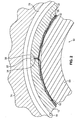
- FIG. 1 is a partial cross-sectional side view of a hydrodynamic fluid film journal bearing system 10.
- FIG. 2 is a cross-sectional view of the hydrodynamic fluid film journal bearing system 10, taken along line 2-2 of FIG. 1 .
- the bearing system 10 includes a journal sleeve 12 formed as a unitary body that defines an outer surface 14, an inner surface 16, a first end 18, and a second end 20.
- the journal sleeve 12 is arranged about a central axis A.
- a key slot 22 (or keyway) is formed in the journal sleeve 12, and the key slot 22 extends entirely through a sleeve wall defined between the outer and inner surfaces 14 and 16 of the journal sleeve 12.
- a number of foils are arranged inside the journal sleeve 12.
- those foils include a bump foil 28, an intermediate foil 30 and a top foil 32.
- the bump foil 28, the intermediate foil 30 and the top foil 32 are each thin sheets of material (e.g., nickel-based alloys or steel) wrapped (or rolled) in a generally cylindrical shape and positioned in a bore of the journal sleeve 12 defined by the substantially cylindrical inner surface 16.
- the bump foil 28 is corrugated, allowing a working fluid or cooling fluid to flow through spaces formed between adjacent corrugations.
- the bump foil 28 is positioned adjacent to the inner surface 16 of the journal sleeve 12, and has a bent end 34 that extends radially outward at least partially into the key slot 22 in order to engage the key slot 22 and retain the bump foil 30 relative to the journal sleeve 12.
- the intermediate foil 30 is positioned adjacent to and radially inward from the bump foil 28, and the top foil is positioned adjacent to and radially inward from the intermediate foil 30.
- the intermediate foil 30 and the top foil 32 are joined together at a bent region 38 that extends radially outward at least partially into the key slot 22, in order to engage the key slot 22 and retain both the intermediate and top foils 30 and 32 relative to the journal sleeve 12.
- a rotatable component like a shaft 60 is positioned inside the journal sleeve 12 and the foils 28, 30 and 32.
- the shaft 60 would rotate into a free end of the top foil 32 tending to open the wound foils (i.e., clockwise with respect to the cross-section of the bearing system 10 shown in FIG. 2 ).
- Rotation of the shaft 60 would cause a working fluid to form a cushion (often referred to as an "air bearing") that supports the shaft 60 while rotating at operating speed with little or no direct contact between the shaft 60 and the top foil 32 of the bearing system 10.
- contact between the shaft 60 and the top foil 32 may still occur at relatively low speed operation, such as during startup and shutdown phases, and due to incidental contact during regular operation.
- the journal sleeve 12 includes a first O-ring land 62 and a second O-ring land 64, a chamfered region 66, and a grooved region defined at the outer surface 14 by a first tapered portion 68, a middle recessed portion 70, and a second tapered portion 72.
- the first O-ring land 62 is located adjacent to the first end 18 of the journal sleeve 12
- the second O-ring land 64 is located adjacent to the second end 20 of the journal sleeve 12.
- the chamfered region 66 is located between the first O-ring land 62 and the first end 18 of the journal sleeve
- the second O-ring land 64 is located immediately adjacent to the second end 20 of the journal sleeve 12 in the illustrated embodiment.
- the first and second O-ring lands 62 and 64 each define a substantially cylindrical region of the outer surface 14 of the journal sleeve 12 that is parallel to the axis A.
- the grooved region defined by the first tapered portion 68, the middle recessed portion 70 and the second tapered portion 72 is located between the first and second O-ring lands 62 and 64.
- the middle recessed portion 70 forms a generally cylindrical region of the outer surface 14 of the journal sleeve 12, and the first and second tapered portions 68 and 72 form generally frustoconical regions of the outer surface 14 that connect the middle recessed portion 70 with the first and second O-ring lands 62 and 64, respectively.
- the middle recessed portion 70 has a smaller outer diameter than the first and second 0-ring lands 62 and 64, which reduces a thickness of the sleeve wall defined between the outer and inner surfaces 14 and 16 of the journal sleeve 12 within the grooved region.
- the reduced thickness of the sleeve wall within the grooved region at the outer surface 14 of the journal sleeve 12 provides weight reduction for the bearing system 10. It will be understood by those of ordinary skill in the art that the dimensions of the features of the journal sleeve 12, and in particular thicknesses of the sleeve wall, will vary as desired for particular applications. Moreover, angles of the first and second tapered portions 68 and 72 can vary as a function of the differences in wall thicknesses between the middle recessed portion 70 and the first and second O-ring lands 62 and 64, although those angles will generally be greater than 0° and less than 90° with respect to the axis A.
- the weight reduction features defined at the outer surface 14 of the journal sleeve 12 need not have any impact on design of the inner surface 16 of the journal sleeve, which can maintain a substantially cylindrical shape.
- the chamfered region 66 is located immediately adjacent to the first end 18 of the journal sleeve 12, between the first end 18 of the journal sleeve 12 and the first O-ring land 62.
- the chamfered region 66 is generally frustoconical in shape and causes the outer surface 14 of the journal sleeve 12 to angle from a greater outer diameter at the first O-ring land 62 to a smaller outer diameter at the first end 18.
- the angle of the chamfered region 66 relative to the axis A can vary as desired for particular applications. As explained further below, the angle defined by the chamfered region 66 helps reduce a risk of damage to O-rings during assembly of the bearing system 10.
- the journal sleeve 12 can be made of a metallic material and shaped using known techniques such as milling, turning and grinding.
- the bearing system 10 further includes a housing 74, a first O-ring 76 and a second O-ring 78. It should be noted that in FIG. 1 , the housing 74 and the first and second O-rings 76 and 78 are shown in cross-section in order to reveal the journal sleeve 12 and a portion of the shaft 60 not shown in cross-section.
- the housing 74 generally defines a bore 80 in which the journal sleeve 12 is positioned.
- the first and second O-rings 76 and 78 are engaged with the housing 74 in respective first and second engagement grooves 82 and 84.
- the first O-ring 76 rests against and engages the first O-ring land 62 of the journal sleeve 12, and the second O-ring 78 rests against and engages the second O-ring land 64 of the journal sleeve 12.
- the first and second O-rings 76 and 78 can be of a conventional type known for use with hydrodynamic fluid film journal bearing systems.
- the hydrodynamic fluid film journal bearing system 10 of the present invention can be assembled as follows.
- the foils 28, 30 and 32 are assembled inside the journal sleeve 12, and the first and second O-rings 76 and 78 are positioned in the engagement grooves 82 and 84, respectively, in the housing 74.
- the journal sleeve 12 (with the foils 28, 30 and 32 assembled therein) is then inserted into the bore 80 of the housing 74, inside the first and second O-rings 76 and 78.
- the first end 18 of the journal sleeve 12 can be inserted into the bore 80 first, such that the chamfered region 66 passes the second O-ring 78 followed by the first O-ring 76.
- the chamfered region 66 as well as the first and second tapered portions 68 and 72 help reduce a risk of damage to the first and second O-rings 76 and 78 during assembly by providing relatively smooth transitions between the first and second O-ring lands 62 and 64 and adjacent outer surfaces regions of the journal sleeve 12 that have smaller outer diameters.
- the first and second O-rings 76 and 78 are susceptible to cutting and tearing during assembly when the journal sleeve 12 is inserted, and the present invention helps reduce the risk of such damage occurring.
- the first and second ends 18 and 20 of the journal sleeve 12 can be readily distinguished. This is important because the hydrodynamic fluid film journal bearing system 10 is configured such that the shaft 60 should rotate in a particular direction relative to the foils 28, 30 and 32, and improper assembly due to insertion of the wrong end of the journal sleeve into the bore 80 of the housing 74 can disrupt that preferred rotational relationship. Therefore, the chamfered region 66 provides assembly foolproofing functionality to help ensure proper assembly of the bearing system 10.
Abstract
Description
- The present invention relates to hydrodynamic fluid film bearing systems.
- Hydrodynamic fluid film journal bearings, also called journal air bearings or foil bearings, can be used to provide support to rotatable components such as shafts. A typical prior art bearing assembly of this type (e.g., as disclosed by
U.S. Pat. No. 5,658,079 ), includes a journal sleeve, a bump foil, an intermediate foil, and a top foil. The bump foil, the intermediate foil and the top foil are wrapped inside the journal sleeve in a substantially cylindrical shape, and those foils are positioned between the journal sleeve and the rotatable component. Each foil has an end that is engaged to the journal sleeve, and can have another end that is free (i.e., not engaged to the journal sleeve). During operation, rotation of the rotatable component causes a working fluid to form a cushion (often referred to as an "air bearing") that supports the rotatable component with little or no direct contact between the rotatable component and the foils of the bearing. - Conventional hydrodynamic fluid film journal bearings have a substantially cylindrical journal sleeve. These cylindrical journal sleeves have walls of uniform thickness defined between an outer diameter surface and an opposite inner diameter surface. Those journal sleeve walls are relatively thick for providing stiffness. However, such thick journal sleeve walls add considerable weight to the bearing. Weight of bearings is an important design consideration, particularly for aerospace applications.
- A hydrodynamic fluid film journal bearing system includes a journal sleeve and one or more hydrodynamic fluid film foils positioned at least partially within the journal sleeve. The journal sleeve defines an inner diameter surface, an outer diameter surface, a wall thickness between the inner and outer diameter surfaces, a first o-ring land, and opposite first and second ends. The wall thickness of the journal sleeve is reduced at a first region located between the first and second ends, the first o-ring land is formed at the outer diameter surface of the journal sleeve adjacent to the first end, and a chamfered region is formed on the outer diameter surface of the journal sleeve between the first o-ring land and the first end of the journal sleeve.
- Viewed from another aspect, the invention provides a hydrodynamic fluid film journal bearing system comprising a rotatable shaft; a journal sleeve positioned about the shaft, the journal sleeve defining an inner diameter surface, an outer diameter surface, a wall thickness between the inner and outer diameter surfaces, and opposite first and second ends; one or more hydrodynamic fluid film foils disposed between the journal sleeve and the shaft; a first o-ring land formed at the outer diameter surface of the journal sleeve adjacent to the first end; a second o-ring land formed at the outer diameter surface of the journal sleeve adjacent to the second end; and a weight reduction groove formed at the outer diameter surface of the journal sleeve, wherein the weight reduction groove reduces the wall thickness of the journal sleeve at a first region located between the first and second o-ring lands, and wherein the weight reduction groove includes at least one tapered portion.
- Viewed from another aspect, the invention provides a hydrodynamic fluid film journal bearing system comprising a journal sleeve formed as a unitary body positioned about the shaft, the journal sleeve defining an inner diameter surface, an outer diameter surface, a wall thickness between the inner and outer diameter surfaces, and opposite first and second ends; one or more hydrodynamic fluid film foils positioned at least partially within the journal sleeve; a first o-ring land formed at the outer diameter surface of the journal sleeve adjacent to the first end; a second o-ring land formed at the outer diameter surface of the journal sleeve adjacent to the second end; a housing having first and second o-ring engagement grooves; a first o-ring engaged between the first o-ring engagement groove in the housing and the first o-ring land of the journal sleeve; a second o-ring engaged between the second o-ring engagement groove in the housing and the second o-ring land of the journal sleeve; and a chamfered region formed on the outer diameter surface of the journal sleeve between the first o-ring land and the first end of the journal sleeve for reducing a risk of damage to the first and second o-rings during assembly of the system.
- Certain embodiments of the invention will now be described by way of example and not limitation.
-
-
FIG. 1 is a partial cross-sectional side view of a hydrodynamic fluid film journal bearing system according to the present invention. -
FIG. 2 is a cross-sectional view of the hydrodynamic fluid film journal bearing system, taken along line 2-2 ofFIG. 1 . - The present invention provides weight reduction for a hydrodynamic fluid film journal bearing system by providing a tailored journal sleeve profile that reduces a wall thickness of at least a portion of a journal sleeve of the bearing system. Furthermore, a journal sleeve according to the present invention includes one or more chamfered regions that help reduce a risk of damage to O-rings during assembly and installation of the bearing system.
-
FIG. 1 is a partial cross-sectional side view of a hydrodynamic fluid filmjournal bearing system 10.FIG. 2 is a cross-sectional view of the hydrodynamic fluid filmjournal bearing system 10, taken along line 2-2 ofFIG. 1 . In general, thebearing system 10 includes ajournal sleeve 12 formed as a unitary body that defines anouter surface 14, aninner surface 16, afirst end 18, and asecond end 20. Thejournal sleeve 12 is arranged about a central axis A. A key slot 22 (or keyway) is formed in thejournal sleeve 12, and thekey slot 22 extends entirely through a sleeve wall defined between the outer andinner surfaces journal sleeve 12. A number of foils are arranged inside thejournal sleeve 12. - As shown in
FIG. 2 , those foils include abump foil 28, anintermediate foil 30 and atop foil 32. Thebump foil 28, theintermediate foil 30 and thetop foil 32 are each thin sheets of material (e.g., nickel-based alloys or steel) wrapped (or rolled) in a generally cylindrical shape and positioned in a bore of thejournal sleeve 12 defined by the substantially cylindricalinner surface 16. Thebump foil 28 is corrugated, allowing a working fluid or cooling fluid to flow through spaces formed between adjacent corrugations. Thebump foil 28 is positioned adjacent to theinner surface 16 of thejournal sleeve 12, and has abent end 34 that extends radially outward at least partially into thekey slot 22 in order to engage thekey slot 22 and retain thebump foil 30 relative to thejournal sleeve 12. Theintermediate foil 30 is positioned adjacent to and radially inward from thebump foil 28, and the top foil is positioned adjacent to and radially inward from theintermediate foil 30. Theintermediate foil 30 and thetop foil 32 are joined together at abent region 38 that extends radially outward at least partially into thekey slot 22, in order to engage thekey slot 22 and retain both the intermediate andtop foils journal sleeve 12. - A rotatable component like a
shaft 60 is positioned inside thejournal sleeve 12 and thefoils shaft 60 would rotate into a free end of thetop foil 32 tending to open the wound foils (i.e., clockwise with respect to the cross-section of thebearing system 10 shown inFIG. 2 ). Rotation of theshaft 60 would cause a working fluid to form a cushion (often referred to as an "air bearing") that supports theshaft 60 while rotating at operating speed with little or no direct contact between theshaft 60 and thetop foil 32 of thebearing system 10. However, contact between theshaft 60 and thetop foil 32 may still occur at relatively low speed operation, such as during startup and shutdown phases, and due to incidental contact during regular operation. - The
journal sleeve 12 includes a first O-ring land 62 and a second O-ring land 64, achamfered region 66, and a grooved region defined at theouter surface 14 by a firsttapered portion 68, a middle recessedportion 70, and a secondtapered portion 72. The first O-ringland 62 is located adjacent to thefirst end 18 of thejournal sleeve 12, and the second O-ringland 64 is located adjacent to thesecond end 20 of thejournal sleeve 12. Thechamfered region 66 is located between the first O-ringland 62 and thefirst end 18 of the journal sleeve, and the second O-ringland 64 is located immediately adjacent to thesecond end 20 of thejournal sleeve 12 in the illustrated embodiment. The first and second O-ring lands outer surface 14 of thejournal sleeve 12 that is parallel to the axis A. - The grooved region defined by the first
tapered portion 68, the middle recessedportion 70 and the secondtapered portion 72 is located between the first and second O-ring lands portion 70 forms a generally cylindrical region of theouter surface 14 of thejournal sleeve 12, and the first and secondtapered portions outer surface 14 that connect the middle recessedportion 70 with the first and second O-ring lands portion 70 has a smaller outer diameter than the first and second 0-ring lands inner surfaces journal sleeve 12 within the grooved region. The reduced thickness of the sleeve wall within the grooved region at theouter surface 14 of thejournal sleeve 12 provides weight reduction for thebearing system 10. It will be understood by those of ordinary skill in the art that the dimensions of the features of thejournal sleeve 12, and in particular thicknesses of the sleeve wall, will vary as desired for particular applications. Moreover, angles of the first and secondtapered portions portion 70 and the first and second O-ring lands outer surface 14 of thejournal sleeve 12 need not have any impact on design of theinner surface 16 of the journal sleeve, which can maintain a substantially cylindrical shape. - The
chamfered region 66 is located immediately adjacent to thefirst end 18 of thejournal sleeve 12, between thefirst end 18 of thejournal sleeve 12 and the first O-ringland 62. Thechamfered region 66 is generally frustoconical in shape and causes theouter surface 14 of thejournal sleeve 12 to angle from a greater outer diameter at the first O-ring land 62 to a smaller outer diameter at thefirst end 18. The angle of thechamfered region 66 relative to the axis A can vary as desired for particular applications. As explained further below, the angle defined by thechamfered region 66 helps reduce a risk of damage to O-rings during assembly of thebearing system 10. - The
journal sleeve 12 can be made of a metallic material and shaped using known techniques such as milling, turning and grinding. - The
bearing system 10 further includes ahousing 74, a first O-ring 76 and a second O-ring 78. It should be noted that inFIG. 1 , thehousing 74 and the first and second O-rings journal sleeve 12 and a portion of theshaft 60 not shown in cross-section. Thehousing 74 generally defines abore 80 in which thejournal sleeve 12 is positioned. In the illustrated embodiment, the first and second O-rings housing 74 in respective first andsecond engagement grooves ring 76 rests against and engages the first O-ring land 62 of thejournal sleeve 12, and the second O-ring 78 rests against and engages the second O-ringland 64 of thejournal sleeve 12. The first and second O-rings - The hydrodynamic fluid film
journal bearing system 10 of the present invention can be assembled as follows. The foils 28, 30 and 32 are assembled inside thejournal sleeve 12, and the first and second O-rings engagement grooves housing 74. The journal sleeve 12 (with thefoils bore 80 of thehousing 74, inside the first and second O-rings first end 18 of thejournal sleeve 12 can be inserted into thebore 80 first, such that the chamferedregion 66 passes the second O-ring 78 followed by the first O-ring 76. By inserting thejournal sleeve 12 in that manner, the chamferedregion 66 as well as the first and secondtapered portions rings journal sleeve 12 that have smaller outer diameters. The first and second O-rings journal sleeve 12 is inserted, and the present invention helps reduce the risk of such damage occurring. - In addition, by having the chamfered
region 66 located immediately adjacent to thefirst end 18 of thejournal sleeve 12 but, in contrast, having the second O-ring land 64 located immediately adjacent to thesecond end 20 of the journal sleeve (i.e., not having another chamfered region immediately adjacent to the second end 20), the first and second ends 18 and 20 of thejournal sleeve 12 can be readily distinguished. This is important because the hydrodynamic fluid filmjournal bearing system 10 is configured such that theshaft 60 should rotate in a particular direction relative to thefoils bore 80 of thehousing 74 can disrupt that preferred rotational relationship. Therefore, the chamferedregion 66 provides assembly foolproofing functionality to help ensure proper assembly of the bearingsystem 10. - Although the present invention has been described with reference to preferred embodiments, workers skilled in the art will recognize that changes may be made in form and detail without departing from the scope of the invention, which is defined by the claims and their equivalents.
Claims (19)
- A hydrodynamic fluid film journal bearing system (10) comprising:a journal sleeve (12) that defines an inner diameter surface (16), an outer diameter surface (14), a wall thickness between the inner and outer diameter surfaces, a first o-ring land (62), and opposite first (18) and second (20) ends, wherein the wall thickness is reduced at a first region (68, 70, 72) located between the first and second ends, wherein first o-ring land (62) is formed at the outer diameter surface of the journal sleeve adjacent to the first end (18), and wherein a chamfered region (66) is formed on the outer diameter surface of the journal sleeve between the first o-ring land (62) and the first end (18) of the journal sleeve (12); andone or more hydrodynamic fluid film foils (28, 30, 32) positioned at least partially within the journal sleeve (12).
- The system of claim 1, wherein the wall thickness of the journal sleeve is reduced by a groove (68, 70, 72) formed at the outer diameter surface (14) of the journal sleeve (12).
- The system of claim 1 or 2 and further comprising:a second o-ring land (64) formed at the outer diameter surface (14) of the journal sleeve (12) adjacent to the second end (20).
- The system of claim 3, wherein the second o-ring land (64) is formed at the outer diameter surface of the journal sleeve immediately adjacent to the second end (20) for assembly foolproofing.
- The system of claim 3 or 4, wherein the wall thickness of the journal sleeve (12) is reduced by a groove formed between the first (62) and second (64) o-ring lands at the outer diameter surface of the journal sleeve, the groove comprising:a middle portion (70);a first tapered portion (68) located between the middle portion (70) and the first o-ring land (62); anda second tapered portion (72) located between the middle portion (70) and the second o-ring land (64).
- The system of claim 5, wherein the middle portion (70) of the groove is substantially cylindrically shaped.
- The system of claim 3, 4, 5 or 6 and further comprising:a housing (74) having first (82) and second (84) o-ring engagement grooves;a first o-ring (76) engaged between the first o-ring engagement groove (82) in the housing and the first o-ring land (62) of the journal sleeve; anda second o-ring (78) engaged between the second o-ring engagement groove (84) in the housing and the second o-ring land (64) of the journal sleeve.
- A hydrodynamic fluid film journal bearing system (10) comprising:a rotatable shaft (60);a journal sleeve (12) positioned about the shaft, the journal sleeve defining an inner diameter surface (16), an outer diameter surface (14), a wall thickness between the inner and outer diameter surfaces, and opposite first (18) and second (20) ends;one or more hydrodynamic fluid film foils (28, 30, 32) disposed between the journal sleeve and the shaft;a first o-ring land (62) formed at the outer diameter surface (14) of the journal sleeve adjacent to the first end (18);a second o-ring land (64) formed at the outer diameter surface (14) of the journal sleeve adjacent to the second end (20); anda weight reduction groove (68, 70, 72) formed at the outer diameter surface of the journal sleeve, wherein the weight reduction groove reduces the wall thickness of the journal sleeve at a first region located between the first and second o-ring lands, and wherein the weight reduction groove includes at least one tapered portion (68, 72).
- The system of claim 8 and further comprising:a chamfered region (66) formed on the outer diameter surface (14) of the journal sleeve between the first o-ring land (62) and the first end (18) of the journal sleeve.
- The system of claim 9, wherein the second o-ring land (64) is formed at the outer diameter surface of the journal sleeve immediately adjacent to the second end (20).
- The system of claim 8, 9 or 10 wherein the weight reduction groove comprises:a middle portion (70);a first tapered portion (68) located between the middle portion (70) and the first o-ring land (62); anda second tapered portion (72) located between the middle portion (70) and the second o-ring land (64).
- The system of claim 11, wherein the middle portion (70) of the weight reduction groove is substantially cylindrically shaped.
- The system of any of claims 8 to 12 and further comprising:a housing (74) having first (82) and second (84) o-ring engagement grooves;a first o-ring (76) engaged between the first o-ring engagement groove (82) in the housing and the first o-ring land (62) of the journal sleeve; anda second o-ring (78) engaged between the second o-ring engagement groove (84) in the housing and the second o-ring land (64) of the journal sleeve.
- A hydrodynamic fluid film journal bearing system (10) comprising:a journal sleeve (12) formed as a unitary body adapted to be positioned about a shaft, the journal sleeve defining an inner diameter surface (16), an outer diameter surface (14), a wall thickness between the inner and outer diameter surfaces, and opposite first (18) and second (20) ends;one or more hydrodynamic fluid film foils (28, 30, 32) positioned at least partially within the journal sleeve;a first o-ring land (62) formed at the outer diameter surface of the journal sleeve adjacent to the first end (18);a second o-ring land (64) formed at the outer diameter surface of the journal sleeve adjacent to the second end (20);a housing (74) having first (82) and second (84) o-ring engagement grooves;a first o-ring (76) engaged between the first o-ring engagement groove (82) in the housing and the first o-ring land (62) of the journal sleeve;a second o-ring (78) engaged between the second o-ring engagement groove (84) in the housing and the second o-ring land (64) of the journal sleeve; anda chamfered region (66) formed on the outer diameter surface of the journal sleeve between the first o-ring land (62) and the first end (18) of the journal sleeve for reducing a risk of damage to the first and second o-rings during assembly of the system.
- The system of claim 14, wherein the second o-ring land (64) is formed at the outer diameter surface of the journal sleeve immediately adjacent to the second end (20).
- The system of claim 14 or 15 and further comprising:a groove (68, 70, 72) formed at the outer diameter surface of the journal sleeve.
- The system of claim 16, wherein the groove reduces the wall thickness of the journal sleeve at a first region located between the first and second o-ring lands (62, 64).
- The system of claim 16 or 17, wherein the groove comprises:a middle portion (70);a first tapered portion (68) located between the middle portion (70) and the first o-ring land (62); anda second tapered portion (72) located between the middle portion (70) and the second o-ring land (64).
- The system of claim 18, wherein the middle portion (70) of the groove is substantially cylindrically shaped.
Applications Claiming Priority (1)
| Application Number | Priority Date | Filing Date | Title |
|---|---|---|---|
| US11/786,796 US7648280B2 (en) | 2007-04-12 | 2007-04-12 | Weight reduction for journal air bearing |
Publications (3)
| Publication Number | Publication Date |
|---|---|
| EP1980761A2 true EP1980761A2 (en) | 2008-10-15 |
| EP1980761A3 EP1980761A3 (en) | 2009-11-04 |
| EP1980761B1 EP1980761B1 (en) | 2011-09-14 |
Family
ID=39591477
Family Applications (1)
| Application Number | Title | Priority Date | Filing Date |
|---|---|---|---|
| EP08250619A Active EP1980761B1 (en) | 2007-04-12 | 2008-02-22 | Weight reduction for journal air bearing |
Country Status (4)
| Country | Link |
|---|---|
| US (1) | US7648280B2 (en) |
| EP (1) | EP1980761B1 (en) |
| JP (1) | JP5269461B2 (en) |
| ES (1) | ES2372646T3 (en) |
Cited By (3)
| Publication number | Priority date | Publication date | Assignee | Title |
|---|---|---|---|---|
| EP2375089A3 (en) * | 2010-03-30 | 2012-05-02 | Honda Motor Co., Ltd. | Dynamic foil gas bearing |
| CN101737154B (en) * | 2009-12-10 | 2013-03-27 | 湖南天雁机械有限责任公司 | Air bearing for turbocharger |
| CN115053077A (en) * | 2020-02-20 | 2022-09-13 | 松下知识产权经营株式会社 | Bearing structure |
Families Citing this family (18)
| Publication number | Priority date | Publication date | Assignee | Title |
|---|---|---|---|---|
| US20070110351A1 (en) * | 2005-11-16 | 2007-05-17 | Honeywell International, Inc. | Centering mechanisms for turbocharger bearings |
| US8496432B2 (en) * | 2010-03-22 | 2013-07-30 | Hamilton Sundstrand Corporation | Thrust bearing cooling path |
| US8496533B2 (en) * | 2010-03-22 | 2013-07-30 | Hamilton Sundstrand Corporation | Journal bearing with dual pass cooling for air machine |
| US8622620B2 (en) * | 2010-09-15 | 2014-01-07 | Hamilton Sundstrand Corporation | Shaft for air bearing and motor cooling in compressor |
| US8529192B2 (en) | 2010-09-15 | 2013-09-10 | Hamilton Sundstrand Corporation | Thrust bearing shaft for thrust and journal air bearing cooling in a compressor |
| US8517665B2 (en) | 2010-12-21 | 2013-08-27 | Hamilton Sundstrand Corporation | Thrust bearing shaft for thrust and journal air bearing cooling in an air machine |
| US8807921B2 (en) * | 2011-04-04 | 2014-08-19 | Hamilton Sundstrand Corporation | Journal air bearing for small shaft diameters |
| JP6051220B2 (en) * | 2011-08-24 | 2016-12-27 | ボーグワーナー インコーポレーテッド | Bearing device |
| US9404534B2 (en) | 2012-11-30 | 2016-08-02 | Honeywell International Inc. | Rotating assemblies of turbomachinery, foil journal bearing assemblies thereof, and methods for producing journals of the foil journal bearing assemblies |
| US8734017B1 (en) | 2013-03-08 | 2014-05-27 | Hamilton Sundstrand Corporation | Air bearing shaft |
| US8920032B2 (en) * | 2013-03-15 | 2014-12-30 | Hamilton Sundstrand Corporation | Bearing sleeve |
| US9028149B2 (en) | 2013-03-15 | 2015-05-12 | Hamilton Sundstrand Corporation | Bearing sleeve |
| US8926182B2 (en) | 2013-03-15 | 2015-01-06 | Hamilton Sundstrand Corporation | Bearing sleeve |
| US8794838B1 (en) | 2013-03-15 | 2014-08-05 | Hamilton Sundstrand Corporation | Bearing sleeve |
| EP3036409B1 (en) * | 2013-08-20 | 2018-10-24 | Borgwarner Inc. | Air bearing arrangement |
| CN106402146B (en) * | 2016-10-12 | 2018-09-07 | 哈尔滨工业大学 | The gas radial foil bearing of flat paillon axial width variation |
| PL233717B1 (en) * | 2017-06-29 | 2019-11-29 | Instytut Masz Przeplywowych Im Roberta Szewalskiego Polskiej Akademii Nauk | Foil bearing |
| US11965520B2 (en) | 2021-11-23 | 2024-04-23 | Samsung Electronics Co., Ltd. | Airfoil journal bearing |
Citations (3)
| Publication number | Priority date | Publication date | Assignee | Title |
|---|---|---|---|---|
| US5209577A (en) | 1991-11-13 | 1993-05-11 | Camco International, Inc. | Downhole rotating machine having compliant radial bearings |
| US5658079A (en) | 1995-06-05 | 1997-08-19 | United Technologies Corporation | Hydrodynamic fluid film journal bearing |
| WO1999014510A1 (en) | 1997-09-12 | 1999-03-25 | United Technologies Corporation | Bearing arrangement for air cycle machine |
Family Cites Families (7)
| Publication number | Priority date | Publication date | Assignee | Title |
|---|---|---|---|---|
| US4552466A (en) | 1984-04-24 | 1985-11-12 | The United States Of America As Represented By The Administrator Of The National Aeronautics And Space Administration | Compliant hydrodynamic fluid journal bearing |
| JPH0493523U (en) * | 1991-01-08 | 1992-08-13 | ||
| US5427455A (en) | 1994-04-18 | 1995-06-27 | Bosley; Robert W. | Compliant foil hydrodynamic fluid film radial bearing |
| US5536087A (en) | 1995-03-02 | 1996-07-16 | Council Of Scientific & Industrial Research | Foil journal bearing having straight foils useful for providing support for high speed rotors and a process for fabricating said bearing |
| JPH09100831A (en) * | 1995-10-09 | 1997-04-15 | Mitsubishi Heavy Ind Ltd | Bearing device |
| JP4401704B2 (en) * | 2003-07-14 | 2010-01-20 | 本田技研工業株式会社 | Foil type hydrodynamic bearing |
| US7070330B2 (en) | 2004-02-19 | 2006-07-04 | R & D Dynamics Corporation | Hydrodynamic fluid film bearing having a key-less foil |
-
2007
- 2007-04-12 US US11/786,796 patent/US7648280B2/en active Active
-
2008
- 2008-02-22 EP EP08250619A patent/EP1980761B1/en active Active
- 2008-02-22 ES ES08250619T patent/ES2372646T3/en active Active
- 2008-03-31 JP JP2008089431A patent/JP5269461B2/en active Active
Patent Citations (3)
| Publication number | Priority date | Publication date | Assignee | Title |
|---|---|---|---|---|
| US5209577A (en) | 1991-11-13 | 1993-05-11 | Camco International, Inc. | Downhole rotating machine having compliant radial bearings |
| US5658079A (en) | 1995-06-05 | 1997-08-19 | United Technologies Corporation | Hydrodynamic fluid film journal bearing |
| WO1999014510A1 (en) | 1997-09-12 | 1999-03-25 | United Technologies Corporation | Bearing arrangement for air cycle machine |
Cited By (4)
| Publication number | Priority date | Publication date | Assignee | Title |
|---|---|---|---|---|
| CN101737154B (en) * | 2009-12-10 | 2013-03-27 | 湖南天雁机械有限责任公司 | Air bearing for turbocharger |
| EP2375089A3 (en) * | 2010-03-30 | 2012-05-02 | Honda Motor Co., Ltd. | Dynamic foil gas bearing |
| US8475048B2 (en) | 2010-03-30 | 2013-07-02 | Honda Motor Co., Ltd. | Dynamic foil gas bearing |
| CN115053077A (en) * | 2020-02-20 | 2022-09-13 | 松下知识产权经营株式会社 | Bearing structure |
Also Published As
| Publication number | Publication date |
|---|---|
| US7648280B2 (en) | 2010-01-19 |
| US20080253705A1 (en) | 2008-10-16 |
| EP1980761B1 (en) | 2011-09-14 |
| ES2372646T3 (en) | 2012-01-25 |
| JP5269461B2 (en) | 2013-08-21 |
| EP1980761A3 (en) | 2009-11-04 |
| JP2008261495A (en) | 2008-10-30 |
Similar Documents
| Publication | Publication Date | Title |
|---|---|---|
| EP1980761B1 (en) | Weight reduction for journal air bearing | |
| JP5253866B2 (en) | Hydrodynamic fluid film journal bearing assembly and method of manufacturing the same | |
| EP0787264B1 (en) | Hydrodynamic fluid film journal bearing | |
| US20160208847A1 (en) | Quad foil journal air bearing | |
| US8371799B2 (en) | Turbo compressor/journal foil bearings with axial retainers | |
| EP3001048B1 (en) | Journal air bearing with air-film-supply vent | |
| US7070330B2 (en) | Hydrodynamic fluid film bearing having a key-less foil | |
| EP1925833A1 (en) | Damper element of bearing, method of manufacturing damper element, bearing, and gas turbine engine | |
| JP5340697B2 (en) | Sliding bearing for internal combustion engine and sliding bearing device | |
| JP2008261496A5 (en) | ||
| WO2013145355A1 (en) | Rolling bearing device | |
| EP3396184B1 (en) | Crossed roller bearing | |
| US5139348A (en) | Bearings | |
| US10371198B2 (en) | Quad foil journal air bearing | |
| JP2009127693A (en) | Bearing creep preventing structure and its manufacturing method | |
| JP2009297830A (en) | Apparatus and method for attaching thrust roller bearing race | |
| JP2009008213A (en) | Roller bearing device and method for assembling same | |
| EP3561323B1 (en) | Foil journal air bearing | |
| WO2017100555A1 (en) | Plain bearing shell with anti-rotation features | |
| JP2017072205A (en) | Slide bearing | |
| JP2008128318A (en) | Thrust bearing structure |
Legal Events
| Date | Code | Title | Description |
|---|---|---|---|
| PUAI | Public reference made under article 153(3) epc to a published international application that has entered the european phase |
Free format text: ORIGINAL CODE: 0009012 |
|
| AK | Designated contracting states |
Kind code of ref document: A2 Designated state(s): AT BE BG CH CY CZ DE DK EE ES FI FR GB GR HR HU IE IS IT LI LT LU LV MC MT NL NO PL PT RO SE SI SK TR |
|
| AX | Request for extension of the european patent |
Extension state: AL BA MK RS |
|
| PUAL | Search report despatched |
Free format text: ORIGINAL CODE: 0009013 |
|
| AK | Designated contracting states |
Kind code of ref document: A3 Designated state(s): AT BE BG CH CY CZ DE DK EE ES FI FR GB GR HR HU IE IS IT LI LT LU LV MC MT NL NO PL PT RO SE SI SK TR |
|
| AX | Request for extension of the european patent |
Extension state: AL BA MK RS |
|
| 17P | Request for examination filed |
Effective date: 20100209 |
|
| 17Q | First examination report despatched |
Effective date: 20100311 |
|
| AKX | Designation fees paid |
Designated state(s): DE ES FR GB |
|
| RIC1 | Information provided on ipc code assigned before grant |
Ipc: F16C 17/12 20060101AFI20110303BHEP Ipc: F16C 27/06 20060101ALI20110303BHEP |
|
| GRAP | Despatch of communication of intention to grant a patent |
Free format text: ORIGINAL CODE: EPIDOSNIGR1 |
|
| GRAS | Grant fee paid |
Free format text: ORIGINAL CODE: EPIDOSNIGR3 |
|
| GRAA | (expected) grant |
Free format text: ORIGINAL CODE: 0009210 |
|
| AK | Designated contracting states |
Kind code of ref document: B1 Designated state(s): DE ES FR GB |
|
| REG | Reference to a national code |
Ref country code: GB Ref legal event code: FG4D |
|
| REG | Reference to a national code |
Ref country code: DE Ref legal event code: R096 Ref document number: 602008009754 Country of ref document: DE Effective date: 20111110 |
|
| REG | Reference to a national code |
Ref country code: ES Ref legal event code: FG2A Ref document number: 2372646 Country of ref document: ES Kind code of ref document: T3 Effective date: 20120125 |
|
| PLBE | No opposition filed within time limit |
Free format text: ORIGINAL CODE: 0009261 |
|
| STAA | Information on the status of an ep patent application or granted ep patent |
Free format text: STATUS: NO OPPOSITION FILED WITHIN TIME LIMIT |
|
| 26N | No opposition filed |
Effective date: 20120615 |
|
| REG | Reference to a national code |
Ref country code: DE Ref legal event code: R097 Ref document number: 602008009754 Country of ref document: DE Effective date: 20120615 |
|
| PGFP | Annual fee paid to national office [announced via postgrant information from national office to epo] |
Ref country code: DE Payment date: 20130220 Year of fee payment: 6 Ref country code: ES Payment date: 20130218 Year of fee payment: 6 |
|
| REG | Reference to a national code |
Ref country code: DE Ref legal event code: R119 Ref document number: 602008009754 Country of ref document: DE |
|
| REG | Reference to a national code |
Ref country code: DE Ref legal event code: R119 Ref document number: 602008009754 Country of ref document: DE Effective date: 20140902 |
|
| PG25 | Lapsed in a contracting state [announced via postgrant information from national office to epo] |
Ref country code: DE Free format text: LAPSE BECAUSE OF NON-PAYMENT OF DUE FEES Effective date: 20140902 |
|
| REG | Reference to a national code |
Ref country code: ES Ref legal event code: FD2A Effective date: 20150327 |
|
| PG25 | Lapsed in a contracting state [announced via postgrant information from national office to epo] |
Ref country code: ES Free format text: LAPSE BECAUSE OF NON-PAYMENT OF DUE FEES Effective date: 20140223 |
|
| REG | Reference to a national code |
Ref country code: FR Ref legal event code: PLFP Year of fee payment: 9 |
|
| REG | Reference to a national code |
Ref country code: FR Ref legal event code: PLFP Year of fee payment: 10 |
|
| REG | Reference to a national code |
Ref country code: FR Ref legal event code: PLFP Year of fee payment: 11 |
|
| PGFP | Annual fee paid to national office [announced via postgrant information from national office to epo] |
Ref country code: FR Payment date: 20230119 Year of fee payment: 16 |
|
| PGFP | Annual fee paid to national office [announced via postgrant information from national office to epo] |
Ref country code: GB Payment date: 20230121 Year of fee payment: 16 |
|
| P01 | Opt-out of the competence of the unified patent court (upc) registered |
Effective date: 20230522 |