EP3000954A1 - Electronic cylinder with waterproof structure - Google Patents
Electronic cylinder with waterproof structure Download PDFInfo
- Publication number
- EP3000954A1 EP3000954A1 EP14186755.6A EP14186755A EP3000954A1 EP 3000954 A1 EP3000954 A1 EP 3000954A1 EP 14186755 A EP14186755 A EP 14186755A EP 3000954 A1 EP3000954 A1 EP 3000954A1
- Authority
- EP
- European Patent Office
- Prior art keywords
- exterior
- motor
- recess
- face
- clutch unit
- Prior art date
- Legal status (The legal status is an assumption and is not a legal conclusion. Google has not performed a legal analysis and makes no representation as to the accuracy of the status listed.)
- Granted
Links
- 238000002347 injection Methods 0.000 claims abstract description 16
- 239000007924 injection Substances 0.000 claims abstract description 16
- 239000000945 filler Substances 0.000 claims abstract description 14
- 230000000694 effects Effects 0.000 claims description 18
- 230000000903 blocking effect Effects 0.000 claims description 6
- 239000004205 dimethyl polysiloxane Substances 0.000 claims description 6
- 229920000435 poly(dimethylsiloxane) Polymers 0.000 claims description 6
- -1 Polydimethylsiloxane Polymers 0.000 claims description 3
- 230000007257 malfunction Effects 0.000 description 7
- XLYOFNOQVPJJNP-UHFFFAOYSA-N water Substances O XLYOFNOQVPJJNP-UHFFFAOYSA-N 0.000 description 6
- 230000009545 invasion Effects 0.000 description 3
- 238000004891 communication Methods 0.000 description 2
- 230000003213 activating effect Effects 0.000 description 1
- 230000032683 aging Effects 0.000 description 1
- 230000005540 biological transmission Effects 0.000 description 1
- 230000007797 corrosion Effects 0.000 description 1
- 238000005260 corrosion Methods 0.000 description 1
- 230000003247 decreasing effect Effects 0.000 description 1
- 230000018109 developmental process Effects 0.000 description 1
- 238000005516 engineering process Methods 0.000 description 1
- 230000008595 infiltration Effects 0.000 description 1
- 238000001764 infiltration Methods 0.000 description 1
- 239000000463 material Substances 0.000 description 1
- 238000012986 modification Methods 0.000 description 1
- 230000004048 modification Effects 0.000 description 1
- 238000007789 sealing Methods 0.000 description 1
- 229920002545 silicone oil Polymers 0.000 description 1
- 238000005728 strengthening Methods 0.000 description 1
- 239000000126 substance Substances 0.000 description 1
- 229940099259 vaseline Drugs 0.000 description 1
Images


Classifications
-
- E—FIXED CONSTRUCTIONS
- E05—LOCKS; KEYS; WINDOW OR DOOR FITTINGS; SAFES
- E05B—LOCKS; ACCESSORIES THEREFOR; HANDCUFFS
- E05B47/00—Operating or controlling locks or other fastening devices by electric or magnetic means
- E05B47/06—Controlling mechanically-operated bolts by electro-magnetically-operated detents
- E05B47/0611—Cylinder locks with electromagnetic control
- E05B47/0638—Cylinder locks with electromagnetic control by disconnecting the rotor
- E05B47/0642—Cylinder locks with electromagnetic control by disconnecting the rotor axially, i.e. with an axially disengaging coupling element
-
- E—FIXED CONSTRUCTIONS
- E05—LOCKS; KEYS; WINDOW OR DOOR FITTINGS; SAFES
- E05B—LOCKS; ACCESSORIES THEREFOR; HANDCUFFS
- E05B17/00—Accessories in connection with locks
- E05B17/002—Weather or dirt protection
-
- E—FIXED CONSTRUCTIONS
- E05—LOCKS; KEYS; WINDOW OR DOOR FITTINGS; SAFES
- E05B—LOCKS; ACCESSORIES THEREFOR; HANDCUFFS
- E05B47/00—Operating or controlling locks or other fastening devices by electric or magnetic means
- E05B47/06—Controlling mechanically-operated bolts by electro-magnetically-operated detents
- E05B47/0611—Cylinder locks with electromagnetic control
- E05B47/0615—Cylinder locks with electromagnetic control operated by handles, e.g. by knobs
-
- E—FIXED CONSTRUCTIONS
- E05—LOCKS; KEYS; WINDOW OR DOOR FITTINGS; SAFES
- E05B—LOCKS; ACCESSORIES THEREFOR; HANDCUFFS
- E05B47/00—Operating or controlling locks or other fastening devices by electric or magnetic means
- E05B47/0001—Operating or controlling locks or other fastening devices by electric or magnetic means with electric actuators; Constructional features thereof
- E05B47/0012—Operating or controlling locks or other fastening devices by electric or magnetic means with electric actuators; Constructional features thereof with rotary electromotors
Definitions
- the present invention relates generally to an electronic cylinder and more particularly to an electronic cylinder having waterproof structure between a motor and other component so as to provide waterproof effect.
- the primary object of using an electronic lock is to prevent theft.
- the electronic lock itself should possess durable wearing or corrosion, lesser damage and malfunction are some major factors what the consumers consider generally when purchasing or selecting the electronic locks.
- the lesser malfunction of electronic lock depends on materials from which the components are fabricated, such as aging and fatigue of plastic substances, service life of electronic elements, motor durability, waterproof, fire-proof and moisture-proof of battery or circuit design play important role and affect the usage span of the electronic lock. In case the electronic lock one uses malfunctions often and hence cannot provide safety measures to his belongings, which in turn may hinder the user to go out safely or enter his house conveniently.
- the motor disposed within electronic cylinder for activating a latch assembly so as to lock and unlock a door is the most important element in an electronic lock.
- Presently available electronic cylinders in the markets are not provided with anti-moisture or waterproof effects. Taiwan being located in sub-tropical area (rainy and humid environment), moisture can easily penetrate through the lock heart or other parts via gaps connecting the components.
- Taiwan being located in sub-tropical area (rainy and humid environment), moisture can easily penetrate through the lock heart or other parts via gaps connecting the components.
- the electronic lock is usually provided on the external door, which adds moisture as rain or splashing water infiltration, resulting in malfunction of internal components in the electronic lock. Therefore, it is highly desired to find a way to protect the invasion of moisture into the motor while strengthening the structure of waterproof function in other parts to enhance waterproof effects of the electronic cylinder, thereby decreasing malfunction of the electronic lock.
- a primary objective of the present invention is to provide an electronic lock, simply an electronic cylinder including a motor which has filled by waterproof filler so as to provide a waterproof structure thereto, so as to permit traditional performance in a way while preventing malfunction of the motor in the other way.
- Another objective of the present invention is to provide an electronic cylinder with enhanced waterproof structure such that waterproof ring and waterproof washers are provided at gaps existing among the elements so as to prevent invasion of water, thereby causing the electronic cylinder of the present invention to possess waterproof effects.
- An electronic cylinder of the present invention accordingly includes an exterior knob; an exterior cylinder core connected securely to an end of the exterior knob; a motor disposed within the exterior cylinder core, having a protrusion block and an axle extending axially and outwardly from the protrusion block; a clutch unit connected operably to the motor; a cam member associated with the clutch unit and the motor for driving a latch assembly to lock or unlock the door upon causing rotation between the clutch unit and the motor; a cylindrical coupler seat disposed between the motor and the clutch unit, including a rear chamber for receiving the clutch unit and a front portion located opposite to the rear chamber and having a front end face provided with a blocking opening constituted by an injection channel indented inwardly from the front end face and extending inwardly and radially from a first point of a periphery confining the front end face, an recess indented inwardly and axially from a bottom surface of the injection channel and an outflow channel indented inwardly from the front end face and extending in
- the protrusion block of the motor is generally cylindrical.
- the recess has a shape complementing with the protrusion block.
- the preventing block 513 is generally semi-circular in shape.
- the waterproof filler is selected from a group consisting of Polydimethylsiloxane (PDMS).
- PDMS Polydimethylsiloxane
- the exterior cylinder core defines an interior chamber for receiving the motor.
- the electronic cylinder of the present invention further includes a waterproof ring sleeved around an outer surface of the cylindrical coupler seat so as to abut hermetically against the interior chamber, thereby providing an additional waterproof effect among the motor, the cylindrical coupler seat and the exterior cylinder core.
- the electronic cylinder of the present invention further includes a first waterproof washer sandwiched between the exterior cylinder core and the exterior knob in order to provide additional waterproof effect therebetween.
- the exterior knob includes an exterior housing and an interior housing that is located inside the exterior housing and that defines the end of the exterior knob for connected securely to the exterior cylinder core.
- the electronic cylinder of the present invention further includes a second waterproof washer disposed between the exterior and interior housings.
- the motor located with the coupler seat is waterproof, thereby preventing damage done onto it.
- the waterproof ring and waterproof washers are disposed among the gaps connecting elements relative to one another, water is prevented from getting into the interior of the electronic cylinder of the present invention, thereby prolonging the service life of the present electronic cylinder.
- Fig. 1 is an exploded view of an electronic cylinder of the present invention having waterproof structure.
- the electronic cylinder of the present invention for a door includes an exterior knob 10, an exterior cylinder core 20, a lock housing 30, a motor 40, a clutch unit 60, a cam member 70 and a sensing device (not visible).
- the exterior knob 10 is generally installed on a front side of the door (not visible), which is provided with a handle 14.
- the exterior cylinder core 20 is disposed on a rear side of the door and is connected securely to an end of the exterior knob 10.
- the motor 40 is disposed within the exterior cylinder core 20.
- the clutch unit 60 is connected operably to the motor 40.
- the assembly of the clutch unit 60 and the motor 20 is disposed within the lock housing 30, which in turn is installed on the rear side of the door.
- the cam member 70 is associated with the clutch unit 60 and the motor 40 for driving a latch assembly which is generally connected with the lock housing 30 to lock or unlock the door with respect to the door frame (not visible) upon causing rotation between the clutch unit 60 and the motor 40.
- the cam member 70 can include a transmission rod, oval-shaped paddle or any other mechanism operably connected to the latch assembly so long it can drive the lock mechanism to open and close the door.
- the electronic cylinder of the present invention further includes an interior knob 90 which is generally installed on the rear side of the door (not visible) and an interior cylinder core 80 interconnecting the interior knob 90 and the clutch unit 60 in a known manner.
- a cylindrical coupler seat 50 is disposed between the motor 40 and the clutch unit 60, includes a rear chamber 501 for receiving movably an extension portion 61 of the clutch unit 60.
- the motor 40 has an annular protrusion block 42 and an axle 41 extending axially and outwardly from the protrusion block 42.
- the structure of the motor 40 should not be limited only the disclosed ones, any driving means can be employed so long as it can engage with the extension portion 61 of the clutch unit 60 so as to cause rotation therebetween.
- the coupler seat 50 has a front portion that located opposite to the rear chamber 501 and that has a front end face provided with a blocking opening 51 constituted by an injection channel 511 indented inwardly from the front end face and extending inwardly and radially from a first point of a periphery confining the front end face, an annular recess 512 indented inwardly and axially from a bottom surface of the injection channel 511 and an outflow channel 514 indented inwardly from the front end face and extending inwardly and radially from a second point of the periphery opposite to the first point to terminate at the recess 512.
- the bottom surface of the recess 512 is formed with a through hole 52 via which the axle 41 extends for operably engaging the extension portion 61 of the clutch unit 60.
- the front portion further has a preventing block 513 formed between the bottom surface of the recess 512 and the outflow channel 514.
- the preventing block 513 is located in a depth with respect to the front end face complementing with the protrusion block 42 of the motor 40 such that once the protrusion block 42 is seated in the recess 512, the front end face of the coupler seat 50 abuts fittingly and sealingly against the motor 40 around the protrusion block 42, thereby forming a communication passage between the coupler seat 50 and the motor 40 constituted by the above mentioned channels and recess.
- the preventing block 513 is generally semi-circular in shape.
- the structure of the preventing block 513 should not be limited only to the disclosed ones, any other structure like cylinder or rectangular can be used so long it can achieve the desired purpose.
- Fig. 2 is a perspective view of the clutch unit 60, the cylindrical coupler seat 50, the motor 40 and the exterior cylinder core 20 cooperatively constituting the electronic cylinder of the present invention
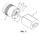
- Fig. 3 is an enlarged view of the cylindrical coupler seat 50 and the motor 40 shown in Fig. 2
- Fig. 4 is a cross-sectional view of assembled elements shown in Fig. 2 .
- the blocking opening 51 defines the communication passage between the coupler seat 50 and the motor 40 constituted by the above mentioned channels and recess.
- a waterproof filler 54 is injected from the injection channel 511 so as to hermetically filling the recess 512 in the coupler seat 50 upon encountering the preventing block 513 and simultaneously filling the ambient space around the axle 41 follow by and the outflow channel 514.
- the entire portion surrounding the protrusion block 42 is replete with the waterproof filler 54 such that in case of invasion of water via the clutch unit 60 and the cam member 70, water cannot penetrate into the motor 40, thereby providing waterproof effect to the motor 40.
- the waterproof filler 54 is selected from a group consisting of Polydimethylsiloxane (PDMS). Any other filler, such as silicone oil and Vaseline, can be used so long they can provide hermetical sealing effect to the motor 40.
- PDMS Polydimethylsiloxane
- Fig. 4 is a cross-sectional view of assembled elements shown in Fig. 2 .
- the exterior cylinder core 20 defines an interior chamber for receiving the motor 40.
- the electronic cylinder of the present invention further includes a waterproof ring 53 sleeved around an outer surface of the cylindrical coupler seat 50 so as to abut hermetically against an annular recess 22 formed in the interior chamber, so that water cannot invade into the gaps formed among the clutch unit 60, the cylindrical coupler seat 50 and the exterior cylinder core 20, thereby providing an additional waterproof effect among the clutch unit 60, the cylindrical coupler seat 50 and the exterior cylinder core 20.
- Fig. 5 shows how a first waterproof washer is sandwiched between the exterior cylinder core 20 and the exterior knob 10 shown in Fig. 1 in order to provide additional waterproof effect in the electronic cylinder of the present invention.
- the electronic cylinder of the present invention further includes a first waterproof washer 21 sandwiched between the exterior cylinder core and the exterior knob 10 in order to provide additional waterproof effect therebetween.
- Fig. 6 is a cross-sectional view illustrating how a second waterproof washer is provided between the exterior cylinder core 20 and in the exterior knob 10 shown in Fig. 1 in order to provide additional waterproof effect in the electronic cylinder of the present invention
- Fig.7 shows an exploded and enlarged view of the exterior knob 10 employed in the electronic cylinder of the present invention.
- the electronic cylinder of the present invention further includes a waterproof washer 21 sandwiched between the exterior cylinder core 20 and the exterior knob 10 in order to provide additional waterproof effect to a chamber 121 formed in the rear side of the exterior knob 10.
- the exterior knob 10 includes an exterior housing 11 and an interior housing 12 that is located inside the exterior housing 11 and that defines the end of the exterior knob 10 for connected securely to the exterior cylinder core 20.
- the electronic cylinder of the present invention includes a waterproof ring 13 disposed in an annular recess 122 formed on an outer surface of the interior housing 12 so as to abut sealingly against the inner surface of the interior housing 11, thereby providing an additional waterproof effect to the exterior knob 10.
- One distinct feature of the present invention resides in that injection of the waterproof filler 54 is finished swiftly due to the following reasons.
- the injection channel 511 and the outflow channel 514 are aligned with each other, and have the same depth with respect to the front end face but a different width relative to each other, wherein the injection channel 511 has a larger width than the outflow channel 514 to facilitate injection of the waterproof filler 54 filling the blocking opening 51.
Landscapes
- Physics & Mathematics (AREA)
- Electromagnetism (AREA)
- Lock And Its Accessories (AREA)
Abstract
Description
- The present invention relates generally to an electronic cylinder and more particularly to an electronic cylinder having waterproof structure between a motor and other component so as to provide waterproof effect.
- The advance of electronic technology results in development of electronic locks having precise and complicated means for identifying or verifying individual identifications, such as input pins, chip sensors, fingerprint recognition, iris diaphragm recognition, thereby tremendously increasing safety personal belongings. The majority of conventional mechanical locks are gradually replaced by digital or electronic locks. Under such circumstances, it is the ultimate goal of the manufacturers to produce electronic locks to meet or fulfill the demand or requirement of the consumers.
- The primary object of using an electronic lock is to prevent theft. In addition to verifying precisely and definitely individual identifications, the electronic lock itself should possess durable wearing or corrosion, lesser damage and malfunction are some major factors what the consumers consider generally when purchasing or selecting the electronic locks. The lesser the malfunction, the more the durability increases, the electronic lock provide the more safety to the users. The lesser malfunction of electronic lock depends on materials from which the components are fabricated, such as aging and fatigue of plastic substances, service life of electronic elements, motor durability, waterproof, fire-proof and moisture-proof of battery or circuit design play important role and affect the usage span of the electronic lock. In case the electronic lock one uses malfunctions often and hence cannot provide safety measures to his belongings, which in turn may hinder the user to go out safely or enter his house conveniently.
- Generally, in addition to verifying and sensing elements, the motor disposed within electronic cylinder for activating a latch assembly so as to lock and unlock a door is the most important element in an electronic lock. Presently available electronic cylinders in the markets are not provided with anti-moisture or waterproof effects. Taiwan being located in sub-tropical area (rainy and humid environment), moisture can easily penetrate through the lock heart or other parts via gaps connecting the components. Especially since the electronic lock is usually provided on the external door, which adds moisture as rain or splashing water infiltration, resulting in malfunction of internal components in the electronic lock. Therefore, it is highly desired to find a way to protect the invasion of moisture into the motor while strengthening the structure of waterproof function in other parts to enhance waterproof effects of the electronic cylinder, thereby decreasing malfunction of the electronic lock.
- A primary objective of the present invention is to provide an electronic lock, simply an electronic cylinder including a motor which has filled by waterproof filler so as to provide a waterproof structure thereto, so as to permit traditional performance in a way while preventing malfunction of the motor in the other way.
- Another objective of the present invention is to provide an electronic cylinder with enhanced waterproof structure such that waterproof ring and waterproof washers are provided at gaps existing among the elements so as to prevent invasion of water, thereby causing the electronic cylinder of the present invention to possess waterproof effects.
- An electronic cylinder of the present invention accordingly includes an exterior knob; an exterior cylinder core connected securely to an end of the exterior knob; a motor disposed within the exterior cylinder core, having a protrusion block and an axle extending axially and outwardly from the protrusion block; a clutch unit connected operably to the motor; a cam member associated with the clutch unit and the motor for driving a latch assembly to lock or unlock the door upon causing rotation between the clutch unit and the motor; a cylindrical coupler seat disposed between the motor and the clutch unit, including a rear chamber for receiving the clutch unit and a front portion located opposite to the rear chamber and having a front end face provided with a blocking opening constituted by an injection channel indented inwardly from the front end face and extending inwardly and radially from a first point of a periphery confining the front end face, an recess indented inwardly and axially from a bottom surface of the injection channel and an outflow channel indented inwardly from the front end face and extending inwardly and radially from a second point of the periphery opposite to the first point to terminate at the recess, the bottom surface of the recess being formed with a through hole permitting extension of the axle for operably engaging the clutch unit, the front portion further having a preventing block formed between the bottom surface of the recess and the an outflow channel, the preventing block being located in a depth with respect to the front end face complementing with the protrusion block of the motor such that once the protrusion block is seated in the recess, the front end face of the coupler seat abuts fittingly against the motor around the protrusion block; and a waterproof filler hermetically filling the recess in the coupler seat.
- In one embodiment of the present invention, the protrusion block of the motor is generally cylindrical. The recess has a shape complementing with the protrusion block.
- In another embodiment of the present invention, the preventing
block 513 is generally semi-circular in shape. - Preferably, the waterproof filler is selected from a group consisting of Polydimethylsiloxane (PDMS).
- According to one embodiment of the present invention, the exterior cylinder core defines an interior chamber for receiving the motor. The electronic cylinder of the present invention further includes a waterproof ring sleeved around an outer surface of the cylindrical coupler seat so as to abut hermetically against the interior chamber, thereby providing an additional waterproof effect among the motor, the cylindrical coupler seat and the exterior cylinder core.
- The electronic cylinder of the present invention further includes a first waterproof washer sandwiched between the exterior cylinder core and the exterior knob in order to provide additional waterproof effect therebetween.
- In yet another embodiment of the present invention, the exterior knob includes an exterior housing and an interior housing that is located inside the exterior housing and that defines the end of the exterior knob for connected securely to the exterior cylinder core. The electronic cylinder of the present invention further includes a second waterproof washer disposed between the exterior and interior housings.
- Owing to the waterproof filler hermetically filling the blocking opening in the cylindrical coupler seat, the motor located with the coupler seat is waterproof, thereby preventing damage done onto it. Simultaneously, since the waterproof ring and waterproof washers are disposed among the gaps connecting elements relative to one another, water is prevented from getting into the interior of the electronic cylinder of the present invention, thereby prolonging the service life of the present electronic cylinder.
- The present invention will be apparent to those skilled in the art by reading the following detailed description of a preferred embodiment thereof, with reference to the attached drawings, in which:
-
Fig. 1 is an exploded view of an electronic cylinder of the present invention having waterproof structure; -
Fig. 2 is a perspective view of a clutch unit, a cylindrical coupler seat, a motor and an exterior cylinder core constituting the electronic cylinder of the present invention; -
Fig. 3 is an enlarged view of the cylindrical coupler seat and the motor shown inFig. 2 ; -
Fig. 4 is a cross-sectional view of assembled elements shown inFig. 2 ; -
Fig. 5 shows how a first waterproof washer is sandwiched between the exterior cylinder core and the exterior knob shown inFig. 1 in order to provide additional waterproof effect in the electronic cylinder of the present invention; -
Fig. 6 is a cross-sectional view illustrating how a second waterproof washer is provided between the exterior cylinder core and in the exterior knob shown inFig. 1 in order to provide additional waterproof effect to the electronic cylinder of the present invention; and -
Fig.7 shows an exploded and enlarged view of the exterior knob employed in the electronic cylinder of the present invention. - The accompanying drawings are included to provide a further understanding of the invention, and are incorporated in and constitute a part of this specification. The drawings illustrate embodiments of the invention and, together with the description, serve to explain the principles of the invention.
-
Fig. 1 is an exploded view of an electronic cylinder of the present invention having waterproof structure. As illustrated, the electronic cylinder of the present invention for a door includes anexterior knob 10, anexterior cylinder core 20, alock housing 30, amotor 40, aclutch unit 60, acam member 70 and a sensing device (not visible). Theexterior knob 10 is generally installed on a front side of the door (not visible), which is provided with ahandle 14. Theexterior cylinder core 20 is disposed on a rear side of the door and is connected securely to an end of theexterior knob 10. Themotor 40 is disposed within theexterior cylinder core 20. Theclutch unit 60 is connected operably to themotor 40. The assembly of theclutch unit 60 and themotor 20 is disposed within thelock housing 30, which in turn is installed on the rear side of the door. Thecam member 70 is associated with theclutch unit 60 and themotor 40 for driving a latch assembly which is generally connected with thelock housing 30 to lock or unlock the door with respect to the door frame (not visible) upon causing rotation between theclutch unit 60 and themotor 40. Thecam member 70 can include a transmission rod, oval-shaped paddle or any other mechanism operably connected to the latch assembly so long it can drive the lock mechanism to open and close the door. The electronic cylinder of the present invention further includes aninterior knob 90 which is generally installed on the rear side of the door (not visible) and aninterior cylinder core 80 interconnecting theinterior knob 90 and theclutch unit 60 in a known manner. - Referring to
Figs. 1 and2 , acylindrical coupler seat 50 is disposed between themotor 40 and theclutch unit 60, includes arear chamber 501 for receiving movably anextension portion 61 of theclutch unit 60. - The
motor 40 has anannular protrusion block 42 and anaxle 41 extending axially and outwardly from theprotrusion block 42. The structure of themotor 40 should not be limited only the disclosed ones, any driving means can be employed so long as it can engage with theextension portion 61 of theclutch unit 60 so as to cause rotation therebetween. - The
coupler seat 50 has a front portion that located opposite to therear chamber 501 and that has a front end face provided with a blockingopening 51 constituted by aninjection channel 511 indented inwardly from the front end face and extending inwardly and radially from a first point of a periphery confining the front end face, anannular recess 512 indented inwardly and axially from a bottom surface of theinjection channel 511 and anoutflow channel 514 indented inwardly from the front end face and extending inwardly and radially from a second point of the periphery opposite to the first point to terminate at therecess 512. The bottom surface of therecess 512 is formed with a throughhole 52 via which theaxle 41 extends for operably engaging theextension portion 61 of theclutch unit 60. The front portion further has a preventingblock 513 formed between the bottom surface of therecess 512 and theoutflow channel 514. The preventingblock 513 is located in a depth with respect to the front end face complementing with theprotrusion block 42 of themotor 40 such that once theprotrusion block 42 is seated in therecess 512, the front end face of thecoupler seat 50 abuts fittingly and sealingly against themotor 40 around theprotrusion block 42, thereby forming a communication passage between thecoupler seat 50 and themotor 40 constituted by the above mentioned channels and recess. In this embodiment, the preventingblock 513 is generally semi-circular in shape. However, the structure of the preventingblock 513 should not be limited only to the disclosed ones, any other structure like cylinder or rectangular can be used so long it can achieve the desired purpose. - Referring
Figs. 2 to 4 , whereinFig. 2 is a perspective view of theclutch unit 60, thecylindrical coupler seat 50, themotor 40 and theexterior cylinder core 20 cooperatively constituting the electronic cylinder of the present invention;Fig. 3 is an enlarged view of thecylindrical coupler seat 50 and themotor 40 shown inFig. 2 ; andFig. 4 is a cross-sectional view of assembled elements shown inFig. 2 . As illustrated, after assembly, the blockingopening 51 defines the communication passage between thecoupler seat 50 and themotor 40 constituted by the above mentioned channels and recess. Under this condition, awaterproof filler 54 is injected from theinjection channel 511 so as to hermetically filling therecess 512 in thecoupler seat 50 upon encountering the preventingblock 513 and simultaneously filling the ambient space around theaxle 41 follow by and theoutflow channel 514. Hence, the entire portion surrounding theprotrusion block 42 is replete with thewaterproof filler 54 such that in case of invasion of water via theclutch unit 60 and thecam member 70, water cannot penetrate into themotor 40, thereby providing waterproof effect to themotor 40. - In this embodiment, the
waterproof filler 54 is selected from a group consisting of Polydimethylsiloxane (PDMS). Any other filler, such as silicone oil and Vaseline, can be used so long they can provide hermetical sealing effect to themotor 40. -
Fig. 4 is a cross-sectional view of assembled elements shown inFig. 2 . As shown, theexterior cylinder core 20 defines an interior chamber for receiving themotor 40. The electronic cylinder of the present invention further includes awaterproof ring 53 sleeved around an outer surface of thecylindrical coupler seat 50 so as to abut hermetically against anannular recess 22 formed in the interior chamber, so that water cannot invade into the gaps formed among theclutch unit 60, thecylindrical coupler seat 50 and theexterior cylinder core 20, thereby providing an additional waterproof effect among theclutch unit 60, thecylindrical coupler seat 50 and theexterior cylinder core 20. -
Fig. 5 shows how a first waterproof washer is sandwiched between theexterior cylinder core 20 and theexterior knob 10 shown inFig. 1 in order to provide additional waterproof effect in the electronic cylinder of the present invention. As shown, the electronic cylinder of the present invention further includes a firstwaterproof washer 21 sandwiched between the exterior cylinder core and theexterior knob 10 in order to provide additional waterproof effect therebetween. - Referring to
Figs. 6 and7 , whereinFig. 6 is a cross-sectional view illustrating how a second waterproof washer is provided between theexterior cylinder core 20 and in theexterior knob 10 shown inFig. 1 in order to provide additional waterproof effect in the electronic cylinder of the present invention; andFig.7 shows an exploded and enlarged view of theexterior knob 10 employed in the electronic cylinder of the present invention. As shown, the electronic cylinder of the present invention further includes awaterproof washer 21 sandwiched between theexterior cylinder core 20 and theexterior knob 10 in order to provide additional waterproof effect to achamber 121 formed in the rear side of theexterior knob 10. Preferably, in this embodiment, theexterior knob 10 includes anexterior housing 11 and aninterior housing 12 that is located inside theexterior housing 11 and that defines the end of theexterior knob 10 for connected securely to theexterior cylinder core 20. The electronic cylinder of the present invention includes awaterproof ring 13 disposed in anannular recess 122 formed on an outer surface of theinterior housing 12 so as to abut sealingly against the inner surface of theinterior housing 11, thereby providing an additional waterproof effect to theexterior knob 10. - One distinct feature of the present invention resides in that injection of the
waterproof filler 54 is finished swiftly due to the following reasons. Theinjection channel 511 and theoutflow channel 514 are aligned with each other, and have the same depth with respect to the front end face but a different width relative to each other, wherein theinjection channel 511 has a larger width than theoutflow channel 514 to facilitate injection of thewaterproof filler 54 filling the blockingopening 51. - Although the present invention has been described with reference to the preferred embodiments thereof, it is apparent to those skilled in the art that a variety of modifications and changes may be made without departing from the scope of the present invention which is intended to be defined by the appended claims.
Claims (9)
- An electronic cylinder for a door lock comprising:an exterior knob;an exterior cylinder core connected securely to an end of said exterior knob;a motor disposed within said exterior cylinder core, having a protrusion block and an axle extending axially and outwardly from said protrusion block ;a clutch unit connected operably to said motor;a cam member associated with said clutch unit and said motor for driving a latch assembly to lock or unlock the door upon causing rotation between said clutch unit and said motor;a cylindrical coupler seat disposed between said motor and said clutch unit, including a rear chamber for receiving said clutch unit and a front portion located opposite to said rear chamber and having a front end face provided with a blocking opening constituted by an injection channel indented inwardly from said front end face and extending inwardly and radially from a first point of a periphery confining said front end face, an recess indented inwardly and axially from a bottom surface of said injection channel and an outflow channel indented inwardly from said front end face and extending inwardly and radially from a second point of the periphery opposite to said first point to terminate at said recess, said bottom surface of said recess being formed with a through hole permitting extension of said axle for operably engaging said clutch unit, said front portion further having a preventing block formed between said bottom surface of said recess and said outflow channel, said preventing block being located in a depth with respect to said front end face complementing with said protrusion block of said motor such that once said protrusion block is seated in said recess, said front end face of said coupler seat abuts fittingly against said motor around said protrusion block; anda waterproof filler hermetically filling said recess in said coupler seat.
- The electronic cylinder according to claim 1, wherein said protrusion block of said motor is generally cylindrical, said recess having a shape complementing with said protrusion block.
- The electronic cylinder according to claim 2, wherein said preventing block is generally semi-circular in shape.
- The electronic cylinder according to claim 1, wherein said preventing block is generally semi-circular in shape.
- The electronic cylinder according to claim 1, wherein said waterproof filler is selected from a group consisting of Polydimethylsiloxane (PDMS).
- The electronic cylinder according to claim 1, wherein said exterior cylinder core defines an interior chamber for receiving said motor, the electronic cylinder further comprising a waterproof ring sleeved around an outer surface of said cylindrical coupler seat so as to abut hermetically against said interior chamber in said exterior cylinder core, thereby providing an additional waterproof effect among said clutch unit, said cylindrical coupler seat and said exterior cylinder core.
- The electronic cylinder according to claim 1, further comprising a waterproof washer sandwiched between said exterior cylinder core and said exterior knob in order to provide additional waterproof effect therebetween.
- The electronic cylinder according to claim 1, wherein said exterior knob includes an exterior housing and an interior housing that is located inside said exterior housing and that defines said end of said exterior knob for connected securely to said exterior cylinder core, said electronic cylinder further comprising a waterproof ring disposed between said exterior and interior housings.
- The electronic cylinder according to claim 1, wherein said injection channel and said outflow channel are aligned with each other, and have the same depth with respect to said front end face but a different width relative to each other, wherein said injection channel has a larger width and deeper depth than said outflow channel to facilitate injection of said waterproof filler filling said recess.
Priority Applications (1)
| Application Number | Priority Date | Filing Date | Title |
|---|---|---|---|
| EP14186755.6A EP3000954B1 (en) | 2014-09-29 | 2014-09-29 | Electronic cylinder with waterproof structure |
Applications Claiming Priority (1)
| Application Number | Priority Date | Filing Date | Title |
|---|---|---|---|
| EP14186755.6A EP3000954B1 (en) | 2014-09-29 | 2014-09-29 | Electronic cylinder with waterproof structure |
Publications (2)
| Publication Number | Publication Date |
|---|---|
| EP3000954A1 true EP3000954A1 (en) | 2016-03-30 |
| EP3000954B1 EP3000954B1 (en) | 2017-04-26 |
Family
ID=51661889
Family Applications (1)
| Application Number | Title | Priority Date | Filing Date |
|---|---|---|---|
| EP14186755.6A Active EP3000954B1 (en) | 2014-09-29 | 2014-09-29 | Electronic cylinder with waterproof structure |
Country Status (1)
| Country | Link |
|---|---|
| EP (1) | EP3000954B1 (en) |
Cited By (2)
| Publication number | Priority date | Publication date | Assignee | Title |
|---|---|---|---|---|
| CN112197001A (en) * | 2020-08-25 | 2021-01-08 | 中国空气动力研究与发展中心低速空气动力研究所 | Protection method of electric cylinder in low-temperature, low-pressure and high-humidity environment |
| EP4092228A1 (en) * | 2021-05-18 | 2022-11-23 | SimonsVoss Technologies GmbH | Electronic lock cylinder with sealed actuator |
Families Citing this family (1)
| Publication number | Priority date | Publication date | Assignee | Title |
|---|---|---|---|---|
| CN106088829B (en) * | 2016-08-02 | 2018-09-07 | 江苏雷利电机股份有限公司 | Door lock driving device and apply its electric control door lock |
Citations (3)
| Publication number | Priority date | Publication date | Assignee | Title |
|---|---|---|---|---|
| EP1707712A1 (en) * | 2005-03-30 | 2006-10-04 | WFE Technology Corp. | Cylinder lock assembly with mechanical and electronic mechanism |
| EP2314808A1 (en) * | 2008-07-15 | 2011-04-27 | Salto Systems, S.L. | Electromechanical cylinder for a lock |
| EP2664736A2 (en) * | 2012-05-15 | 2013-11-20 | WFE Technology Corp. | Actuating motor set of electronic lock |
-
2014
- 2014-09-29 EP EP14186755.6A patent/EP3000954B1/en active Active
Patent Citations (3)
| Publication number | Priority date | Publication date | Assignee | Title |
|---|---|---|---|---|
| EP1707712A1 (en) * | 2005-03-30 | 2006-10-04 | WFE Technology Corp. | Cylinder lock assembly with mechanical and electronic mechanism |
| EP2314808A1 (en) * | 2008-07-15 | 2011-04-27 | Salto Systems, S.L. | Electromechanical cylinder for a lock |
| EP2664736A2 (en) * | 2012-05-15 | 2013-11-20 | WFE Technology Corp. | Actuating motor set of electronic lock |
Cited By (2)
| Publication number | Priority date | Publication date | Assignee | Title |
|---|---|---|---|---|
| CN112197001A (en) * | 2020-08-25 | 2021-01-08 | 中国空气动力研究与发展中心低速空气动力研究所 | Protection method of electric cylinder in low-temperature, low-pressure and high-humidity environment |
| EP4092228A1 (en) * | 2021-05-18 | 2022-11-23 | SimonsVoss Technologies GmbH | Electronic lock cylinder with sealed actuator |
Also Published As
| Publication number | Publication date |
|---|---|
| EP3000954B1 (en) | 2017-04-26 |
Similar Documents
| Publication | Publication Date | Title |
|---|---|---|
| US9577487B2 (en) | Electronic cylinder with waterproof structure | |
| EP3000954B1 (en) | Electronic cylinder with waterproof structure | |
| KR20170076688A (en) | Lock with water-resistant touch keypad | |
| US9565910B2 (en) | Waterproof protective case for an electronic device | |
| AU2013299337B2 (en) | Housing for a portable electronic device | |
| US6467316B1 (en) | Protective sleeve for a padlock | |
| US10709220B2 (en) | Protective device case | |
| WO2008107046A1 (en) | External handle on doors or hatches of vehicles | |
| EP1582670A2 (en) | Vehicle door handle device | |
| US20130200768A1 (en) | Waterproof structure for electronic device | |
| US20130113348A1 (en) | Ruggedized case for hand-held electronic device | |
| FR2915796A1 (en) | DEVICE FOR REMOVING THE INTERFERENCE PHENOMENON BETWEEN CAPACITIVE DETECTION AREAS OF A SENSOR | |
| EP2749718A1 (en) | External handle device for vehicle door | |
| WO2005080152A3 (en) | Steering lock assembly | |
| CN104488015A (en) | Lock bolt | |
| KR101020083B1 (en) | A Water Meter Checking Device | |
| US10170855B2 (en) | Waterproof component having a cover with excessive displacement prevention wall | |
| JP2013045850A (en) | Protection cover and electronic apparatus equipped with the same | |
| KR101279872B1 (en) | Digital door lock cover | |
| TWI553208B (en) | Electronic lock of the waterproof structure | |
| KR200479092Y1 (en) | Fixing means for door locks | |
| JP6261044B2 (en) | Waterproof jack | |
| KR200492220Y1 (en) | Electronic key holder of wrist band type | |
| US20060227031A1 (en) | Remote control device protector | |
| TWI697266B (en) | Electronic device |
Legal Events
| Date | Code | Title | Description |
|---|---|---|---|
| PUAI | Public reference made under article 153(3) epc to a published international application that has entered the european phase |
Free format text: ORIGINAL CODE: 0009012 |
|
| AK | Designated contracting states |
Kind code of ref document: A1 Designated state(s): AL AT BE BG CH CY CZ DE DK EE ES FI FR GB GR HR HU IE IS IT LI LT LU LV MC MK MT NL NO PL PT RO RS SE SI SK SM TR |
|
| AX | Request for extension of the european patent |
Extension state: BA ME |
|
| 17P | Request for examination filed |
Effective date: 20160428 |
|
| RBV | Designated contracting states (corrected) |
Designated state(s): AL AT BE BG CH CY CZ DE DK EE ES FI FR GB GR HR HU IE IS IT LI LT LU LV MC MK MT NL NO PL PT RO RS SE SI SK SM TR |
|
| GRAP | Despatch of communication of intention to grant a patent |
Free format text: ORIGINAL CODE: EPIDOSNIGR1 |
|
| INTG | Intention to grant announced |
Effective date: 20161214 |
|
| GRAS | Grant fee paid |
Free format text: ORIGINAL CODE: EPIDOSNIGR3 |
|
| GRAA | (expected) grant |
Free format text: ORIGINAL CODE: 0009210 |
|
| AK | Designated contracting states |
Kind code of ref document: B1 Designated state(s): AL AT BE BG CH CY CZ DE DK EE ES FI FR GB GR HR HU IE IS IT LI LT LU LV MC MK MT NL NO PL PT RO RS SE SI SK SM TR |
|
| REG | Reference to a national code |
Ref country code: GB Ref legal event code: FG4D |
|
| REG | Reference to a national code |
Ref country code: CH Ref legal event code: EP |
|
| REG | Reference to a national code |
Ref country code: AT Ref legal event code: REF Ref document number: 888025 Country of ref document: AT Kind code of ref document: T Effective date: 20170515 |
|
| REG | Reference to a national code |
Ref country code: IE Ref legal event code: FG4D |
|
| REG | Reference to a national code |
Ref country code: DE Ref legal event code: R096 Ref document number: 602014008982 Country of ref document: DE |
|
| REG | Reference to a national code |
Ref country code: FR Ref legal event code: PLFP Year of fee payment: 4 |
|
| REG | Reference to a national code |
Ref country code: NL Ref legal event code: MP Effective date: 20170426 |
|
| REG | Reference to a national code |
Ref country code: LT Ref legal event code: MG4D |
|
| REG | Reference to a national code |
Ref country code: AT Ref legal event code: MK05 Ref document number: 888025 Country of ref document: AT Kind code of ref document: T Effective date: 20170426 |
|
| PG25 | Lapsed in a contracting state [announced via postgrant information from national office to epo] |
Ref country code: NL Free format text: LAPSE BECAUSE OF FAILURE TO SUBMIT A TRANSLATION OF THE DESCRIPTION OR TO PAY THE FEE WITHIN THE PRESCRIBED TIME-LIMIT Effective date: 20170426 |
|
| PG25 | Lapsed in a contracting state [announced via postgrant information from national office to epo] |
Ref country code: FI Free format text: LAPSE BECAUSE OF FAILURE TO SUBMIT A TRANSLATION OF THE DESCRIPTION OR TO PAY THE FEE WITHIN THE PRESCRIBED TIME-LIMIT Effective date: 20170426 Ref country code: HR Free format text: LAPSE BECAUSE OF FAILURE TO SUBMIT A TRANSLATION OF THE DESCRIPTION OR TO PAY THE FEE WITHIN THE PRESCRIBED TIME-LIMIT Effective date: 20170426 Ref country code: NO Free format text: LAPSE BECAUSE OF FAILURE TO SUBMIT A TRANSLATION OF THE DESCRIPTION OR TO PAY THE FEE WITHIN THE PRESCRIBED TIME-LIMIT Effective date: 20170726 Ref country code: ES Free format text: LAPSE BECAUSE OF FAILURE TO SUBMIT A TRANSLATION OF THE DESCRIPTION OR TO PAY THE FEE WITHIN THE PRESCRIBED TIME-LIMIT Effective date: 20170426 Ref country code: AT Free format text: LAPSE BECAUSE OF FAILURE TO SUBMIT A TRANSLATION OF THE DESCRIPTION OR TO PAY THE FEE WITHIN THE PRESCRIBED TIME-LIMIT Effective date: 20170426 Ref country code: LT Free format text: LAPSE BECAUSE OF FAILURE TO SUBMIT A TRANSLATION OF THE DESCRIPTION OR TO PAY THE FEE WITHIN THE PRESCRIBED TIME-LIMIT Effective date: 20170426 Ref country code: GR Free format text: LAPSE BECAUSE OF FAILURE TO SUBMIT A TRANSLATION OF THE DESCRIPTION OR TO PAY THE FEE WITHIN THE PRESCRIBED TIME-LIMIT Effective date: 20170727 |
|
| PG25 | Lapsed in a contracting state [announced via postgrant information from national office to epo] |
Ref country code: IS Free format text: LAPSE BECAUSE OF FAILURE TO SUBMIT A TRANSLATION OF THE DESCRIPTION OR TO PAY THE FEE WITHIN THE PRESCRIBED TIME-LIMIT Effective date: 20170826 Ref country code: LV Free format text: LAPSE BECAUSE OF FAILURE TO SUBMIT A TRANSLATION OF THE DESCRIPTION OR TO PAY THE FEE WITHIN THE PRESCRIBED TIME-LIMIT Effective date: 20170426 Ref country code: PL Free format text: LAPSE BECAUSE OF FAILURE TO SUBMIT A TRANSLATION OF THE DESCRIPTION OR TO PAY THE FEE WITHIN THE PRESCRIBED TIME-LIMIT Effective date: 20170426 Ref country code: BG Free format text: LAPSE BECAUSE OF FAILURE TO SUBMIT A TRANSLATION OF THE DESCRIPTION OR TO PAY THE FEE WITHIN THE PRESCRIBED TIME-LIMIT Effective date: 20170726 Ref country code: SE Free format text: LAPSE BECAUSE OF FAILURE TO SUBMIT A TRANSLATION OF THE DESCRIPTION OR TO PAY THE FEE WITHIN THE PRESCRIBED TIME-LIMIT Effective date: 20170426 Ref country code: RS Free format text: LAPSE BECAUSE OF FAILURE TO SUBMIT A TRANSLATION OF THE DESCRIPTION OR TO PAY THE FEE WITHIN THE PRESCRIBED TIME-LIMIT Effective date: 20170426 |
|
| REG | Reference to a national code |
Ref country code: DE Ref legal event code: R097 Ref document number: 602014008982 Country of ref document: DE |
|
| PG25 | Lapsed in a contracting state [announced via postgrant information from national office to epo] |
Ref country code: RO Free format text: LAPSE BECAUSE OF FAILURE TO SUBMIT A TRANSLATION OF THE DESCRIPTION OR TO PAY THE FEE WITHIN THE PRESCRIBED TIME-LIMIT Effective date: 20170426 Ref country code: EE Free format text: LAPSE BECAUSE OF FAILURE TO SUBMIT A TRANSLATION OF THE DESCRIPTION OR TO PAY THE FEE WITHIN THE PRESCRIBED TIME-LIMIT Effective date: 20170426 Ref country code: CZ Free format text: LAPSE BECAUSE OF FAILURE TO SUBMIT A TRANSLATION OF THE DESCRIPTION OR TO PAY THE FEE WITHIN THE PRESCRIBED TIME-LIMIT Effective date: 20170426 Ref country code: DK Free format text: LAPSE BECAUSE OF FAILURE TO SUBMIT A TRANSLATION OF THE DESCRIPTION OR TO PAY THE FEE WITHIN THE PRESCRIBED TIME-LIMIT Effective date: 20170426 Ref country code: SK Free format text: LAPSE BECAUSE OF FAILURE TO SUBMIT A TRANSLATION OF THE DESCRIPTION OR TO PAY THE FEE WITHIN THE PRESCRIBED TIME-LIMIT Effective date: 20170426 |
|
| PG25 | Lapsed in a contracting state [announced via postgrant information from national office to epo] |
Ref country code: SM Free format text: LAPSE BECAUSE OF FAILURE TO SUBMIT A TRANSLATION OF THE DESCRIPTION OR TO PAY THE FEE WITHIN THE PRESCRIBED TIME-LIMIT Effective date: 20170426 |
|
| PLBE | No opposition filed within time limit |
Free format text: ORIGINAL CODE: 0009261 |
|
| STAA | Information on the status of an ep patent application or granted ep patent |
Free format text: STATUS: NO OPPOSITION FILED WITHIN TIME LIMIT |
|
| 26N | No opposition filed |
Effective date: 20180129 |
|
| REG | Reference to a national code |
Ref country code: CH Ref legal event code: PL |
|
| PG25 | Lapsed in a contracting state [announced via postgrant information from national office to epo] |
Ref country code: SI Free format text: LAPSE BECAUSE OF FAILURE TO SUBMIT A TRANSLATION OF THE DESCRIPTION OR TO PAY THE FEE WITHIN THE PRESCRIBED TIME-LIMIT Effective date: 20170426 Ref country code: MC Free format text: LAPSE BECAUSE OF FAILURE TO SUBMIT A TRANSLATION OF THE DESCRIPTION OR TO PAY THE FEE WITHIN THE PRESCRIBED TIME-LIMIT Effective date: 20170426 |
|
| REG | Reference to a national code |
Ref country code: IE Ref legal event code: MM4A |
|
| REG | Reference to a national code |
Ref country code: BE Ref legal event code: MM Effective date: 20170930 |
|
| PG25 | Lapsed in a contracting state [announced via postgrant information from national office to epo] |
Ref country code: LU Free format text: LAPSE BECAUSE OF NON-PAYMENT OF DUE FEES Effective date: 20170929 |
|
| REG | Reference to a national code |
Ref country code: FR Ref legal event code: PLFP Year of fee payment: 5 |
|
| PG25 | Lapsed in a contracting state [announced via postgrant information from national office to epo] |
Ref country code: CH Free format text: LAPSE BECAUSE OF NON-PAYMENT OF DUE FEES Effective date: 20170930 Ref country code: LI Free format text: LAPSE BECAUSE OF NON-PAYMENT OF DUE FEES Effective date: 20170930 Ref country code: IE Free format text: LAPSE BECAUSE OF NON-PAYMENT OF DUE FEES Effective date: 20170929 |
|
| PG25 | Lapsed in a contracting state [announced via postgrant information from national office to epo] |
Ref country code: BE Free format text: LAPSE BECAUSE OF NON-PAYMENT OF DUE FEES Effective date: 20170930 |
|
| PG25 | Lapsed in a contracting state [announced via postgrant information from national office to epo] |
Ref country code: MT Free format text: LAPSE BECAUSE OF NON-PAYMENT OF DUE FEES Effective date: 20170929 |
|
| PG25 | Lapsed in a contracting state [announced via postgrant information from national office to epo] |
Ref country code: HU Free format text: LAPSE BECAUSE OF FAILURE TO SUBMIT A TRANSLATION OF THE DESCRIPTION OR TO PAY THE FEE WITHIN THE PRESCRIBED TIME-LIMIT; INVALID AB INITIO Effective date: 20140929 |
|
| PG25 | Lapsed in a contracting state [announced via postgrant information from national office to epo] |
Ref country code: CY Free format text: LAPSE BECAUSE OF FAILURE TO SUBMIT A TRANSLATION OF THE DESCRIPTION OR TO PAY THE FEE WITHIN THE PRESCRIBED TIME-LIMIT Effective date: 20170426 |
|
| PG25 | Lapsed in a contracting state [announced via postgrant information from national office to epo] |
Ref country code: MK Free format text: LAPSE BECAUSE OF FAILURE TO SUBMIT A TRANSLATION OF THE DESCRIPTION OR TO PAY THE FEE WITHIN THE PRESCRIBED TIME-LIMIT Effective date: 20170426 |
|
| PG25 | Lapsed in a contracting state [announced via postgrant information from national office to epo] |
Ref country code: TR Free format text: LAPSE BECAUSE OF FAILURE TO SUBMIT A TRANSLATION OF THE DESCRIPTION OR TO PAY THE FEE WITHIN THE PRESCRIBED TIME-LIMIT Effective date: 20170426 |
|
| PG25 | Lapsed in a contracting state [announced via postgrant information from national office to epo] |
Ref country code: PT Free format text: LAPSE BECAUSE OF FAILURE TO SUBMIT A TRANSLATION OF THE DESCRIPTION OR TO PAY THE FEE WITHIN THE PRESCRIBED TIME-LIMIT Effective date: 20170426 |
|
| PG25 | Lapsed in a contracting state [announced via postgrant information from national office to epo] |
Ref country code: AL Free format text: LAPSE BECAUSE OF FAILURE TO SUBMIT A TRANSLATION OF THE DESCRIPTION OR TO PAY THE FEE WITHIN THE PRESCRIBED TIME-LIMIT Effective date: 20170426 |
|
| REG | Reference to a national code |
Ref country code: DE Ref legal event code: R082 Ref document number: 602014008982 Country of ref document: DE Representative=s name: BAUER WAGNER PELLENGAHR SROKA PATENT- & RECHTS, DE |
|
| PGFP | Annual fee paid to national office [announced via postgrant information from national office to epo] |
Ref country code: FR Payment date: 20230607 Year of fee payment: 10 |
|
| PGFP | Annual fee paid to national office [announced via postgrant information from national office to epo] |
Ref country code: IT Payment date: 20230810 Year of fee payment: 10 Ref country code: GB Payment date: 20230703 Year of fee payment: 10 |
|
| PGFP | Annual fee paid to national office [announced via postgrant information from national office to epo] |
Ref country code: DE Payment date: 20230930 Year of fee payment: 10 |