EP3000909A1 - Coating process - Google Patents
Coating process Download PDFInfo
- Publication number
- EP3000909A1 EP3000909A1 EP15184448.7A EP15184448A EP3000909A1 EP 3000909 A1 EP3000909 A1 EP 3000909A1 EP 15184448 A EP15184448 A EP 15184448A EP 3000909 A1 EP3000909 A1 EP 3000909A1
- Authority
- EP
- European Patent Office
- Prior art keywords
- coating
- component
- applying
- head portion
- coating process
- Prior art date
- Legal status (The legal status is an assumption and is not a legal conclusion. Google has not performed a legal analysis and makes no representation as to the accuracy of the status listed.)
- Withdrawn
Links
Images



Classifications
-
- C—CHEMISTRY; METALLURGY
- C23—COATING METALLIC MATERIAL; COATING MATERIAL WITH METALLIC MATERIAL; CHEMICAL SURFACE TREATMENT; DIFFUSION TREATMENT OF METALLIC MATERIAL; COATING BY VACUUM EVAPORATION, BY SPUTTERING, BY ION IMPLANTATION OR BY CHEMICAL VAPOUR DEPOSITION, IN GENERAL; INHIBITING CORROSION OF METALLIC MATERIAL OR INCRUSTATION IN GENERAL
- C23C—COATING METALLIC MATERIAL; COATING MATERIAL WITH METALLIC MATERIAL; SURFACE TREATMENT OF METALLIC MATERIAL BY DIFFUSION INTO THE SURFACE, BY CHEMICAL CONVERSION OR SUBSTITUTION; COATING BY VACUUM EVAPORATION, BY SPUTTERING, BY ION IMPLANTATION OR BY CHEMICAL VAPOUR DEPOSITION, IN GENERAL
- C23C4/00—Coating by spraying the coating material in the molten state, e.g. by flame, plasma or electric discharge
- C23C4/02—Pretreatment of the material to be coated, e.g. for coating on selected surface areas
-
- C—CHEMISTRY; METALLURGY
- C23—COATING METALLIC MATERIAL; COATING MATERIAL WITH METALLIC MATERIAL; CHEMICAL SURFACE TREATMENT; DIFFUSION TREATMENT OF METALLIC MATERIAL; COATING BY VACUUM EVAPORATION, BY SPUTTERING, BY ION IMPLANTATION OR BY CHEMICAL VAPOUR DEPOSITION, IN GENERAL; INHIBITING CORROSION OF METALLIC MATERIAL OR INCRUSTATION IN GENERAL
- C23C—COATING METALLIC MATERIAL; COATING MATERIAL WITH METALLIC MATERIAL; SURFACE TREATMENT OF METALLIC MATERIAL BY DIFFUSION INTO THE SURFACE, BY CHEMICAL CONVERSION OR SUBSTITUTION; COATING BY VACUUM EVAPORATION, BY SPUTTERING, BY ION IMPLANTATION OR BY CHEMICAL VAPOUR DEPOSITION, IN GENERAL
- C23C28/00—Coating for obtaining at least two superposed coatings either by methods not provided for in a single one of groups C23C2/00 - C23C26/00 or by combinations of methods provided for in subclasses C23C and C25C or C25D
-
- B—PERFORMING OPERATIONS; TRANSPORTING
- B05—SPRAYING OR ATOMISING IN GENERAL; APPLYING FLUENT MATERIALS TO SURFACES, IN GENERAL
- B05B—SPRAYING APPARATUS; ATOMISING APPARATUS; NOZZLES
- B05B13/00—Machines or plants for applying liquids or other fluent materials to surfaces of objects or other work by spraying, not covered by groups B05B1/00 - B05B11/00
- B05B13/02—Means for supporting work; Arrangement or mounting of spray heads; Adaptation or arrangement of means for feeding work
- B05B13/04—Means for supporting work; Arrangement or mounting of spray heads; Adaptation or arrangement of means for feeding work the spray heads being moved during spraying operation
- B05B13/0431—Means for supporting work; Arrangement or mounting of spray heads; Adaptation or arrangement of means for feeding work the spray heads being moved during spraying operation with spray heads moved by robots or articulated arms, e.g. for applying liquid or other fluent material to three-dimensional [3D] surfaces
-
- C—CHEMISTRY; METALLURGY
- C23—COATING METALLIC MATERIAL; COATING MATERIAL WITH METALLIC MATERIAL; CHEMICAL SURFACE TREATMENT; DIFFUSION TREATMENT OF METALLIC MATERIAL; COATING BY VACUUM EVAPORATION, BY SPUTTERING, BY ION IMPLANTATION OR BY CHEMICAL VAPOUR DEPOSITION, IN GENERAL; INHIBITING CORROSION OF METALLIC MATERIAL OR INCRUSTATION IN GENERAL
- C23C—COATING METALLIC MATERIAL; COATING MATERIAL WITH METALLIC MATERIAL; SURFACE TREATMENT OF METALLIC MATERIAL BY DIFFUSION INTO THE SURFACE, BY CHEMICAL CONVERSION OR SUBSTITUTION; COATING BY VACUUM EVAPORATION, BY SPUTTERING, BY ION IMPLANTATION OR BY CHEMICAL VAPOUR DEPOSITION, IN GENERAL
- C23C4/00—Coating by spraying the coating material in the molten state, e.g. by flame, plasma or electric discharge
- C23C4/12—Coating by spraying the coating material in the molten state, e.g. by flame, plasma or electric discharge characterised by the method of spraying
-
- C—CHEMISTRY; METALLURGY
- C23—COATING METALLIC MATERIAL; COATING MATERIAL WITH METALLIC MATERIAL; CHEMICAL SURFACE TREATMENT; DIFFUSION TREATMENT OF METALLIC MATERIAL; COATING BY VACUUM EVAPORATION, BY SPUTTERING, BY ION IMPLANTATION OR BY CHEMICAL VAPOUR DEPOSITION, IN GENERAL; INHIBITING CORROSION OF METALLIC MATERIAL OR INCRUSTATION IN GENERAL
- C23C—COATING METALLIC MATERIAL; COATING MATERIAL WITH METALLIC MATERIAL; SURFACE TREATMENT OF METALLIC MATERIAL BY DIFFUSION INTO THE SURFACE, BY CHEMICAL CONVERSION OR SUBSTITUTION; COATING BY VACUUM EVAPORATION, BY SPUTTERING, BY ION IMPLANTATION OR BY CHEMICAL VAPOUR DEPOSITION, IN GENERAL
- C23C4/00—Coating by spraying the coating material in the molten state, e.g. by flame, plasma or electric discharge
- C23C4/12—Coating by spraying the coating material in the molten state, e.g. by flame, plasma or electric discharge characterised by the method of spraying
- C23C4/129—Flame spraying
-
- C—CHEMISTRY; METALLURGY
- C23—COATING METALLIC MATERIAL; COATING MATERIAL WITH METALLIC MATERIAL; CHEMICAL SURFACE TREATMENT; DIFFUSION TREATMENT OF METALLIC MATERIAL; COATING BY VACUUM EVAPORATION, BY SPUTTERING, BY ION IMPLANTATION OR BY CHEMICAL VAPOUR DEPOSITION, IN GENERAL; INHIBITING CORROSION OF METALLIC MATERIAL OR INCRUSTATION IN GENERAL
- C23C—COATING METALLIC MATERIAL; COATING MATERIAL WITH METALLIC MATERIAL; SURFACE TREATMENT OF METALLIC MATERIAL BY DIFFUSION INTO THE SURFACE, BY CHEMICAL CONVERSION OR SUBSTITUTION; COATING BY VACUUM EVAPORATION, BY SPUTTERING, BY ION IMPLANTATION OR BY CHEMICAL VAPOUR DEPOSITION, IN GENERAL
- C23C4/00—Coating by spraying the coating material in the molten state, e.g. by flame, plasma or electric discharge
- C23C4/12—Coating by spraying the coating material in the molten state, e.g. by flame, plasma or electric discharge characterised by the method of spraying
- C23C4/134—Plasma spraying
-
- B—PERFORMING OPERATIONS; TRANSPORTING
- B05—SPRAYING OR ATOMISING IN GENERAL; APPLYING FLUENT MATERIALS TO SURFACES, IN GENERAL
- B05D—PROCESSES FOR APPLYING FLUENT MATERIALS TO SURFACES, IN GENERAL
- B05D1/00—Processes for applying liquids or other fluent materials
- B05D1/32—Processes for applying liquids or other fluent materials using means for protecting parts of a surface not to be coated, e.g. using stencils, resists
-
- B—PERFORMING OPERATIONS; TRANSPORTING
- B23—MACHINE TOOLS; METAL-WORKING NOT OTHERWISE PROVIDED FOR
- B23P—METAL-WORKING NOT OTHERWISE PROVIDED FOR; COMBINED OPERATIONS; UNIVERSAL MACHINE TOOLS
- B23P2700/00—Indexing scheme relating to the articles being treated, e.g. manufactured, repaired, assembled, connected or other operations covered in the subgroups
- B23P2700/06—Cooling passages of turbine components, e.g. unblocking or preventing blocking of cooling passages of turbine components
-
- F—MECHANICAL ENGINEERING; LIGHTING; HEATING; WEAPONS; BLASTING
- F05—INDEXING SCHEMES RELATING TO ENGINES OR PUMPS IN VARIOUS SUBCLASSES OF CLASSES F01-F04
- F05D—INDEXING SCHEME FOR ASPECTS RELATING TO NON-POSITIVE-DISPLACEMENT MACHINES OR ENGINES, GAS-TURBINES OR JET-PROPULSION PLANTS
- F05D2230/00—Manufacture
- F05D2230/30—Manufacture with deposition of material
Definitions
- the present invention is directed generally toward a coating process. More specifically, the present invention is directed to a coating process including applying more than one coating layer to a component within an enclosed coating system.
- Turbine components are often run at high temperatures to provide maximum operating efficiency.
- the temperature at which a turbine can run may be limited by the temperature capabilities of the individual turbine components.
- various methods have been developed.
- One method for increasing the temperature capabilities of a turbine component includes the incorporation of internal cooling holes, through which cool air is forced during turbine engine operation. As cooling air is fed from the cooler side of the component wall through a cooling hole outlet on the hot side, the rushing air assists in lowering the temperature of the hot metal surface. Additionally, the cool air may provide film cooling on the surface of the turbine component.
- turbine components include both cooling holes and various coatings applied over the surface of the component.
- coatings such as a bond coat and a thermal barrier coating (TBC).
- TBC thermal barrier coating
- turbine components include both cooling holes and various coatings applied over the surface of the component.
- the cooling holes are masked before coating.
- the application of multiple coatings may diminish the masking material, particularly when multiple application techniques are used. To decrease the diminishing of the masking material, it may be desirable to re-apply the masking material between the application of multiple coating layers.
- the masking material is applied manually. Due to the elevated temperatures during the application of the coatings, the component is typically cooled before an operator is able to safely remove the component from the coating fixture and manually apply the masking material. Cooling the component, removing the component from the coating fixture, manually applying the masking material, and re-fixturing the component before applying the next layer of coating increases coating time, increases coating cost, and decrease efficiency of the coating process.
- a coating process includes positioning a component within an enclosed coating system, the enclosed coating system including a coating apparatus, applying a first coating over at least a portion of the component, then robotically applying a mask to the component, then applying a second coating over at least the portion of the component. The component remains within the enclosed coating system throughout the coating process.
- a coating process includes positioning a component within an enclosed coating system, applying a first coating over at least a portion of the component with a coating apparatus; then removing a first coating head portion of the coating apparatus and replacing the first coating head portion with a masking head portion; then robotically applying a mask to the component with the coating apparatus; then removing the masking head portion of the coating apparatus and replacing the masking head portion with a second coating head portion; and then applying a second coating over at least a portion of the component with the coating apparatus; wherein the component remains within the enclosed coating system throughout the coating process.
- a coating process includes positioning a component within an enclosed coating system, high-velocity oxygen fuel coating at least a portion of the component with a coating apparatus, then removing a coating head portion of the coating apparatus and replacing the coating head portion with a masking head portion, then robotically applying a mask to the component with the coating apparatus, then removing the masking head portion of the coating apparatus and replacing the masking head portion with an air-plasma head portion, and then air-plasma spraying the component with the coating apparatus.
- Embodiments of the present disclosure in comparison to articles and methods not using one or more of the features disclosed herein, increase masking efficiency, increase coating efficiency, decrease or eliminate cooling of a component prior to masking, provide a removable masking head, decrease total cycle time for a coating process, provide masking within a coating cell, provides automated masking, decrease coating cost, decrease labor cost, decreases or eliminates un-fixturing and re-fixturing of components during coating, or a combination thereof.
- an enclosed coating system 103 includes a component support 120 and a coating apparatus 130 positioned within a housing 140.
- the enclosed coating system 103 includes an enclosure or space having a controlled or controllable atmosphere, or isolation from an exterior environment.
- the component support 120 includes any article for supporting a component 101, such as, but not limited to, a two-axis part table.
- the coating apparatus 130 includes at least one head portion 131 secured to a support member 133. In another embodiment, as illustrated in FIGS.
- the at least one head portion 131 includes a first coating head portion 109, a second coating head portion 113, a masking head portion 111, or a combination thereof
- the at least one head portion 131 is detachably secured to the support member 133.
- the support member 133 includes any suitable member for supporting and/or moving the at least one head portion 131, such as a robot arm.
- the robot arm is shown as a six-axis robot arm in FIG. 1 ; however, as will be appreciated by one skilled in the art, the robot arm may include more or less axes to provide varying degrees of articulation, as needed.
- a coating process 100 includes positioning (step 202) the component 101 within the enclosed coating system 103 and applying a first coating 106 (step 204) over at least a portion 105 of the component 101.
- the coating process 100 includes robotically applying (step 206) a mask 107 to the component 101, then applying a second coating 108 (step 208) over at least the portion 105 of the component 101.
- the first coating 106, the mask 107, and/or the second coating 108 are applied with the coating apparatus 130.
- the coating process 100 includes repeating the applying (step 206) of the mask 107 and/or applying one or more additional coating layers.
- the coating process 100 is devoid or substantially devoid of additional steps, such as, but not limited to, cooling steps, processing steps, un-fixturing steps, re-fixturing steps, or a combination thereof.
- additional steps such as, but not limited to, cooling steps, processing steps, un-fixturing steps, re-fixturing steps, or a combination thereof.
- the component 101 remains within the enclosed coating system 103 throughout the coating process 100.
- the component 101 includes any suitable component for receiving a coating and/or the mask 107 thereon, such as, but not limited to, a blade or bucket, a nozzle, a shroud, a vane, a transition piece, a liner, any other turbine component, or a combination thereof.
- the component 101 includes one or more features formed in a surface thereof, the one or more features including, but not limited to, apertures, such as cooling holes; cavities; recesses; or a combination thereof.
- a first masking material 110 is deposited within and/or over the one or more features, prior to the applying the first coating 106 (step 204).
- the first masking material 110 is applied by any suitable technique, such as, but not limited to, manually, with the coating apparatus 130, prior to positioning the component 101 within the enclosed coating system 103, subsequent to positioning the component 101 within the enclosed coating system 103, or a combination thereof.
- the applying (step 206) of the mask 107 includes depositing a second masking material 112 within the one or more features, and/or over the first masking material 110, the second masking material 112 being the same as or different from the first masking material 110.
- the first masking material 110 is diminished during the applying of the first coating 106 (step 204), decreasing an amount and/or level of the first masking material 110 with the one or more features.
- the second masking material 112 is then deposited over the diminished first masking material 110, forming the mask 107 within and/or over the one or more features.
- the second masking material 112 is applied over the first masking material 110, the second masking material 112 providing increased masking during the applying of the second coating 108 (step 208).
- the first masking material 110 and/or the second masking material 112 include any suitable material for decreasing or eliminating deposition of the first coating 106, the second coating 108, and/or any other coating onto and/or within an area covered by the mask 107.
- Suitable masking materials include, but are not limited to, radiation-curable materials; adhesives; silicon-based materials; ceramic and/or ceramic-like materials; graphite; metallic materials, such as Co-Cr-Mo; or a combination thereof.
- the ceramic materials and/or ceramic-like materials include, but are not limited to, aluminum oxide, zirconium oxide, hafnium oxide, yttria-stabilized zirconium oxide; derivatives of aluminum oxide, zirconium oxide, hafnium oxide, yttria-stabilized zirconium oxide; or a combination thereof.
- the first masking material 110 and/or the second masking material 112 are selected based upon an application method of the first coating 106 and/or the second coating 108, respectively.
- the mask 107 includes a metallic material formed outside the enclosed coating system 103.
- the applying (step 206) of the mask 107 formed outside the enclosed coating system 103 includes positioning the mask 107 over the component 101.
- the applying of the first coating 106 (step 204) and/or the applying of the second coating 108 (step 208) includes any suitable method for applying one or more coating layers over the component 101.
- Suitable methods include, but are not limited to, high-velocity oxygen fuel (HVOF) spraying, air-plasma spray (APS), high-velocity air fuel (HVAF) spraying, vacuum plasma spray (VPS), electron-beam physical vapor deposition (EBPVD), chemical vapor deposition (CVD), ion plasma deposition (IPD), combustion spraying with powder or rod, cold spray, sol gel, electrophoretic deposition, tape casting, polymer derived ceramic coating, slurry coating, dip-application, vacuum-coating application, curtain-coating application, brush-application, roll-coat application, agglomeration and sintering followed by spray drying, or a combination thereof.
- HVOF high-velocity oxygen fuel
- APS air-plasma spray
- HVAC vacuum plasma spray
- EBPVD electron-beam physical
- the first coating 106 and the second coating 108 may be applied by the same or different coating methods.
- the first coating 106 and the second coating 108 are applied with the first coating head portion 109, the first coating head portion 109 applying the first coating 106 (step 204) and the second coating 108 (step 208) with the HVOF spraying.
- the first coating 106 is applied with the first coating head portion 109 and the second coating 108 is applied with a second coating head portion 113, the first coating head portion 109 applying the first coating 106 (step 204) with the HVOF spraying, and the second coating head portion 113 applying the second coating 108 (step 208) with the APS.
- the masking head portion 111 secured to the support member 133 provides the robotically applying (step 206) of the mask 107 to the component 101.
- the masking head portion 111 includes an application device, a curing device, and/or a location device.
- the application device includes any suitable device for depositing the masking material over the surface of the component 101 and/or the one or more features formed therein. As illustrated in FIGS. 3 and 5 , one suitable application device includes a syringe. Other suitable application devices include, but are not limited to, a printing device, a spray device, or a combination thereof.
- the curing device includes any suitable device for curing the mask 107, such as, but not limited to, an ultraviolet curing device, a thermal curing device, or a combination thereof
- the enclosed coating system 103 is selectively devoid or substantially devoid of conditions that cure the masking material.
- the enclosed coating system 103 may be devoid or substantially devoid of heat, ultra-violet (UV) light, infrared (IR) light, other forms of radiation that may result in undesirable curing, or a combination thereof.
- the curing device of the masking head portion 111 selectively cures the masking material during and/or after the robotically applying (step 206) the mask 107.
- the selective curing of the masking material with the curing device provides increased control over a geometry of the mask 107.
- the selective curing of the masking material forms the mask 107 having a geometry complementary to the one or more features.
- the location device includes any device for detecting the one or more features formed in the surface of the component 101, such as, for example, a laser; a structured laser scanner; an infrared detector; an electromagnetic probe; a visually-aided mechanism for location detection including, but not limited to, a camera and/or optical based metrology; or a combination thereof.
- detecting the one or more features formed in the surface of the component 101 includes individually detecting the features with the location device.
- detecting the one or more features includes detecting fewer than all of the features and estimating a position of the rest of the features.
- detecting the one or more features may include obtaining location data from at least a portion of the component by detecting the features with the location device, then interpolating location data of a remainder of the component from the obtained location data.
- the coating apparatus 130 and/or the location device is provided with nominal positions of the one or more features, the nominal positions being provided from a component model (e.g., an original equipment manufacturer (OEM) model, a computer-aided design (CAD) model), a scan of the component 101, or a combination thereof.
- a component model e.g., an original equipment manufacturer (OEM) model, a computer-aided design (CAD) model
- the coating apparatus 130 includes more than one of the head portions 131 secured thereto.
- both the first coating head portion 109 and the second coating heat portion 113 are secured to the support member 133.
- the masking head portion 111 is also secured to the support member 133.
- Each of the more than one head portions 131 may be detachably or integrally secured to the support member 133.
- the coating apparatus 130 is capable of applying one or more coatings and/or masking materials without removing or replacing the head portions 131.
- the coating process 100 includes removing (step 410) the first coating head portion 109 of the coating apparatus 130 after the applying of the first coating 106 (step 204), and replacing (step 412) the first coating head portion 109 with the masking head portion 111 prior to the robotically applying (step 206) of the mask 107.
- the coating process 100 includes removing (step 414) the masking head portion 111 of the coating apparatus 130 after the robotically applying (step 206) of the mask 107, and replacing (step 416) the masking head portion 111 with the second coating head portion 113 prior to the applying of the second coating 108 (step 208).
- the masking head portion 111 is detachably secured to the support member 133, and the first coating head portion 109 is interchangeable with the second coating head portion 113.
- the applying of the first coating 106 (step 204) and/or the second coating 108 (step 208) increases a temperature of the component 101 to a temperature above ambient temperature.
- the temperature of the component 101 remains above a safe handling temperature for at least about 20 minutes, at least about 30 minutes, at least about 45 minutes, at least about 30 to about 60 minutes, or any combination, sub-combination, range, or sub-range thereof.
- Safe handling temperatures include, but are not limited to, up to about 75° F, up to about 100° F, up to about 125° F, or any combination, sub-combination, range, or sub-range thereof.
- the applying (step 206) of the mask 107 decreases or eliminates a cooling time after the applying of the first coating 106 (step 204), decreases an overall cycle time for the process, decreases manual touch time of the component 101, provides the curing of the masking material within the enclosed coating system 103 (e.g., in an environment that is selectively devoid or substantially devoid of conditions that cure the masking material), or a combination thereof.
- the applying (step 206) of the mask 107 within the enclosed coating system 103 decreases or eliminates an un-fixturing and re-fixturing of the component 101 during the coating process 100, which further decreases or eliminates the cooling time after the applying of the first coating 106 (step 204), the overall cycle time, manual touch time of the component 101; provides the curing of the masking material within the enclosed coating system 103; or a combination thereof.
- the coating process 100 including the applying (step 206) of the mask 107 while the temperature of the component 101 is above ambient temperature decreases or eliminates a traditional cool down time of up to one hour and a manual masking time of up to three hours.
- the coating process 100 including the applying (step 206) of the mask 107 while the temperature of the component 101 is above ambient temperature is completed in less than one hour.
- completing the coating process 100 in less than one hour is provided as an example, one skilled in the art will appreciate that the coating process 100 is not so limited, and that component and/or process specifics will dictate actual cycle time.
Landscapes
- Chemical & Material Sciences (AREA)
- Engineering & Computer Science (AREA)
- Plasma & Fusion (AREA)
- Physics & Mathematics (AREA)
- Organic Chemistry (AREA)
- Metallurgy (AREA)
- Mechanical Engineering (AREA)
- Materials Engineering (AREA)
- Chemical Kinetics & Catalysis (AREA)
- Robotics (AREA)
- Details Or Accessories Of Spraying Plant Or Apparatus (AREA)
- Application Of Or Painting With Fluid Materials (AREA)
- Coating By Spraying Or Casting (AREA)
Abstract
Description
- The present invention is directed generally toward a coating process. More specifically, the present invention is directed to a coating process including applying more than one coating layer to a component within an enclosed coating system.
- Turbine components are often run at high temperatures to provide maximum operating efficiency. However, the temperature at which a turbine can run may be limited by the temperature capabilities of the individual turbine components. In order to increase the temperature capabilities of turbine components, various methods have been developed. One method for increasing the temperature capabilities of a turbine component includes the incorporation of internal cooling holes, through which cool air is forced during turbine engine operation. As cooling air is fed from the cooler side of the component wall through a cooling hole outlet on the hot side, the rushing air assists in lowering the temperature of the hot metal surface. Additionally, the cool air may provide film cooling on the surface of the turbine component.
- Another technique for increasing the temperature capabilities of a turbine component includes the application of coatings, such as a bond coat and a thermal barrier coating (TBC). Often, turbine components include both cooling holes and various coatings applied over the surface of the component. Typically, when coatings are applied over the surface of a component having cooling holes formed therein, the cooling holes are masked before coating. However, the application of multiple coatings may diminish the masking material, particularly when multiple application techniques are used. To decrease the diminishing of the masking material, it may be desirable to re-apply the masking material between the application of multiple coating layers.
- Often, the masking material is applied manually. Due to the elevated temperatures during the application of the coatings, the component is typically cooled before an operator is able to safely remove the component from the coating fixture and manually apply the masking material. Cooling the component, removing the component from the coating fixture, manually applying the masking material, and re-fixturing the component before applying the next layer of coating increases coating time, increases coating cost, and decrease efficiency of the coating process.
- A coating process with improvements would be desirable in the art.
- In one embodiment, a coating process includes positioning a component within an enclosed coating system, the enclosed coating system including a coating apparatus, applying a first coating over at least a portion of the component, then robotically applying a mask to the component, then applying a second coating over at least the portion of the component. The component remains within the enclosed coating system throughout the coating process.
- In another embodiment, a coating process includes positioning a component within an enclosed coating system, applying a first coating over at least a portion of the component with a coating apparatus; then removing a first coating head portion of the coating apparatus and replacing the first coating head portion with a masking head portion; then robotically applying a mask to the component with the coating apparatus; then removing the masking head portion of the coating apparatus and replacing the masking head portion with a second coating head portion; and then applying a second coating over at least a portion of the component with the coating apparatus; wherein the component remains within the enclosed coating system throughout the coating process.
- In another embodiment, a coating process includes positioning a component within an enclosed coating system, high-velocity oxygen fuel coating at least a portion of the component with a coating apparatus, then removing a coating head portion of the coating apparatus and replacing the coating head portion with a masking head portion, then robotically applying a mask to the component with the coating apparatus, then removing the masking head portion of the coating apparatus and replacing the masking head portion with an air-plasma head portion, and then air-plasma spraying the component with the coating apparatus.
- Various features and advantages of the present invention will be apparent from the following more detailed description of the preferred embodiments, taken in conjunction with the accompanying drawings which illustrate, by way of example, the principles of the invention. In the drawings:
-
FIG. 1 is a perspective view of an enclosed coating system. -
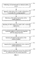
FIG. 2 is a flow chart of a coating process, according to an embodiment of the disclosure. -
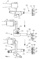
FIG. 3 is a process view of the coating process ofFIG. 2 . -
FIG. 4 is a flow chart of a coating process, according to an embodiment of the disclosure. -
FIG. 5 is a process view of the coating process ofFIG. 4 . - Wherever possible, the same reference numbers will be used throughout the drawings to represent the same parts.
- Provided is a coating process. Embodiments of the present disclosure, in comparison to articles and methods not using one or more of the features disclosed herein, increase masking efficiency, increase coating efficiency, decrease or eliminate cooling of a component prior to masking, provide a removable masking head, decrease total cycle time for a coating process, provide masking within a coating cell, provides automated masking, decrease coating cost, decrease labor cost, decreases or eliminates un-fixturing and re-fixturing of components during coating, or a combination thereof.
- Referring to
FIG. 1 , an enclosedcoating system 103 includes acomponent support 120 and acoating apparatus 130 positioned within ahousing 140. The enclosedcoating system 103 includes an enclosure or space having a controlled or controllable atmosphere, or isolation from an exterior environment. Thecomponent support 120 includes any article for supporting acomponent 101, such as, but not limited to, a two-axis part table. In one embodiment, thecoating apparatus 130 includes at least onehead portion 131 secured to asupport member 133. In another embodiment, as illustrated inFIGS. 3 and5 , the at least onehead portion 131 includes a firstcoating head portion 109, a secondcoating head portion 113, amasking head portion 111, or a combination thereof In a further embodiment, the at least onehead portion 131 is detachably secured to thesupport member 133. Thesupport member 133 includes any suitable member for supporting and/or moving the at least onehead portion 131, such as a robot arm. The robot arm is shown as a six-axis robot arm inFIG. 1 ; however, as will be appreciated by one skilled in the art, the robot arm may include more or less axes to provide varying degrees of articulation, as needed. - Referring to
FIGS. 2-3 , in one embodiment, a coating process 100 includes positioning (step 202) thecomponent 101 within the enclosedcoating system 103 and applying a first coating 106 (step 204) over at least aportion 105 of thecomponent 101. After applying the first coating 106 (step 204), the coating process 100 includes robotically applying (step 206) amask 107 to thecomponent 101, then applying a second coating 108 (step 208) over at least theportion 105 of thecomponent 101. In another embodiment, thefirst coating 106, themask 107, and/or thesecond coating 108 are applied with thecoating apparatus 130. In another embodiment, the coating process 100 includes repeating the applying (step 206) of themask 107 and/or applying one or more additional coating layers. In a further embodiment, the coating process 100 is devoid or substantially devoid of additional steps, such as, but not limited to, cooling steps, processing steps, un-fixturing steps, re-fixturing steps, or a combination thereof. Thecomponent 101 remains within the enclosedcoating system 103 throughout the coating process 100. - The
component 101 includes any suitable component for receiving a coating and/or themask 107 thereon, such as, but not limited to, a blade or bucket, a nozzle, a shroud, a vane, a transition piece, a liner, any other turbine component, or a combination thereof. In one embodiment, thecomponent 101 includes one or more features formed in a surface thereof, the one or more features including, but not limited to, apertures, such as cooling holes; cavities; recesses; or a combination thereof. In another embodiment, afirst masking material 110 is deposited within and/or over the one or more features, prior to the applying the first coating 106 (step 204). Thefirst masking material 110 is applied by any suitable technique, such as, but not limited to, manually, with thecoating apparatus 130, prior to positioning thecomponent 101 within the enclosedcoating system 103, subsequent to positioning thecomponent 101 within the enclosedcoating system 103, or a combination thereof. In a further embodiment, the applying (step 206) of themask 107 includes depositing asecond masking material 112 within the one or more features, and/or over thefirst masking material 110, thesecond masking material 112 being the same as or different from thefirst masking material 110. In one example, thefirst masking material 110 is diminished during the applying of the first coating 106 (step 204), decreasing an amount and/or level of thefirst masking material 110 with the one or more features. Thesecond masking material 112 is then deposited over the diminishedfirst masking material 110, forming themask 107 within and/or over the one or more features. In another example, thesecond masking material 112 is applied over thefirst masking material 110, thesecond masking material 112 providing increased masking during the applying of the second coating 108 (step 208). - The
first masking material 110 and/or thesecond masking material 112 include any suitable material for decreasing or eliminating deposition of thefirst coating 106, thesecond coating 108, and/or any other coating onto and/or within an area covered by themask 107. Suitable masking materials include, but are not limited to, radiation-curable materials; adhesives; silicon-based materials; ceramic and/or ceramic-like materials; graphite; metallic materials, such as Co-Cr-Mo; or a combination thereof. The ceramic materials and/or ceramic-like materials include, but are not limited to, aluminum oxide, zirconium oxide, hafnium oxide, yttria-stabilized zirconium oxide; derivatives of aluminum oxide, zirconium oxide, hafnium oxide, yttria-stabilized zirconium oxide; or a combination thereof. In one embodiment, thefirst masking material 110 and/or thesecond masking material 112 are selected based upon an application method of thefirst coating 106 and/or thesecond coating 108, respectively. In another embodiment, themask 107 includes a metallic material formed outside the enclosedcoating system 103. The applying (step 206) of themask 107 formed outside the enclosedcoating system 103 includes positioning themask 107 over thecomponent 101. - The applying of the first coating 106 (step 204) and/or the applying of the second coating 108 (step 208) includes any suitable method for applying one or more coating layers over the
component 101. Suitable methods include, but are not limited to, high-velocity oxygen fuel (HVOF) spraying, air-plasma spray (APS), high-velocity air fuel (HVAF) spraying, vacuum plasma spray (VPS), electron-beam physical vapor deposition (EBPVD), chemical vapor deposition (CVD), ion plasma deposition (IPD), combustion spraying with powder or rod, cold spray, sol gel, electrophoretic deposition, tape casting, polymer derived ceramic coating, slurry coating, dip-application, vacuum-coating application, curtain-coating application, brush-application, roll-coat application, agglomeration and sintering followed by spray drying, or a combination thereof. - The
first coating 106 and thesecond coating 108 may be applied by the same or different coating methods. In one example, thefirst coating 106 and thesecond coating 108 are applied with the firstcoating head portion 109, the firstcoating head portion 109 applying the first coating 106 (step 204) and the second coating 108 (step 208) with the HVOF spraying. In another example, thefirst coating 106 is applied with the firstcoating head portion 109 and thesecond coating 108 is applied with a secondcoating head portion 113, the firstcoating head portion 109 applying the first coating 106 (step 204) with the HVOF spraying, and the secondcoating head portion 113 applying the second coating 108 (step 208) with the APS. - The
masking head portion 111 secured to thesupport member 133 provides the robotically applying (step 206) of themask 107 to thecomponent 101. In one embodiment, themasking head portion 111 includes an application device, a curing device, and/or a location device. The application device includes any suitable device for depositing the masking material over the surface of thecomponent 101 and/or the one or more features formed therein. As illustrated inFIGS. 3 and5 , one suitable application device includes a syringe. Other suitable application devices include, but are not limited to, a printing device, a spray device, or a combination thereof. - The curing device includes any suitable device for curing the
mask 107, such as, but not limited to, an ultraviolet curing device, a thermal curing device, or a combination thereof In one embodiment, theenclosed coating system 103 is selectively devoid or substantially devoid of conditions that cure the masking material. For example, theenclosed coating system 103 may be devoid or substantially devoid of heat, ultra-violet (UV) light, infrared (IR) light, other forms of radiation that may result in undesirable curing, or a combination thereof. In another embodiment, the curing device of the maskinghead portion 111 selectively cures the masking material during and/or after the robotically applying (step 206) themask 107. The selective curing of the masking material with the curing device provides increased control over a geometry of themask 107. In a further embodiment, the selective curing of the masking material forms themask 107 having a geometry complementary to the one or more features. - The location device includes any device for detecting the one or more features formed in the surface of the
component 101, such as, for example, a laser; a structured laser scanner; an infrared detector; an electromagnetic probe; a visually-aided mechanism for location detection including, but not limited to, a camera and/or optical based metrology; or a combination thereof. In one embodiment, detecting the one or more features formed in the surface of thecomponent 101 includes individually detecting the features with the location device. In another embodiment, detecting the one or more features includes detecting fewer than all of the features and estimating a position of the rest of the features. For example, detecting the one or more features may include obtaining location data from at least a portion of the component by detecting the features with the location device, then interpolating location data of a remainder of the component from the obtained location data. In a further embodiment, thecoating apparatus 130 and/or the location device is provided with nominal positions of the one or more features, the nominal positions being provided from a component model (e.g., an original equipment manufacturer (OEM) model, a computer-aided design (CAD) model), a scan of thecomponent 101, or a combination thereof. - Referring to
FIG. 3 , in one embodiment, thecoating apparatus 130 includes more than one of thehead portions 131 secured thereto. In another embodiment, both the firstcoating head portion 109 and the secondcoating heat portion 113 are secured to thesupport member 133. In a further embodiment, as illustrated inFIG. 3 , the maskinghead portion 111 is also secured to thesupport member 133. Each of the more than onehead portions 131 may be detachably or integrally secured to thesupport member 133. When more than one of thehead portions 131 is secured to thesupport member 133, thecoating apparatus 130 is capable of applying one or more coatings and/or masking materials without removing or replacing thehead portions 131. - In one embodiment, as illustrated in
FIGS. 4-5 , one or more of thehead portions 131 are interchangeable. In another embodiment, the coating process 100 includes removing (step 410) the firstcoating head portion 109 of thecoating apparatus 130 after the applying of the first coating 106 (step 204), and replacing (step 412) the firstcoating head portion 109 with the maskinghead portion 111 prior to the robotically applying (step 206) of themask 107. In a further embodiment, the coating process 100 includes removing (step 414) the maskinghead portion 111 of thecoating apparatus 130 after the robotically applying (step 206) of themask 107, and replacing (step 416) the maskinghead portion 111 with the secondcoating head portion 113 prior to the applying of the second coating 108 (step 208). Alternatively, the maskinghead portion 111 is detachably secured to thesupport member 133, and the firstcoating head portion 109 is interchangeable with the secondcoating head portion 113. - The applying of the first coating 106 (step 204) and/or the second coating 108 (step 208) increases a temperature of the
component 101 to a temperature above ambient temperature. In one embodiment, after the applying of the first coating 106 (step 204) or the second coating 108 (step 208), the temperature of thecomponent 101 remains above a safe handling temperature for at least about 20 minutes, at least about 30 minutes, at least about 45 minutes, at least about 30 to about 60 minutes, or any combination, sub-combination, range, or sub-range thereof. Safe handling temperatures include, but are not limited to, up to about 75° F, up to about 100° F, up to about 125° F, or any combination, sub-combination, range, or sub-range thereof. In another embodiment, the maskinghead portion 111 secured to thesupport member 133 in addition to the firstcoating head portion 109 and/or the second coating head portion 113 (FIG. 3 ), or in place of the firstcoating head portion 109 and/or the second coating head portion 113 (FIG. 5 ), applies themask 107 to thecomponent 101 while the temperature of thecomponent 101 is above ambient temperature and/or safe handling temperature. - The applying (step 206) of the mask 107 (see
FIGS. 3 and5 ) while the temperature of thecomponent 101 is above ambient temperature and/or safe handling temperature decreases or eliminates a cooling time after the applying of the first coating 106 (step 204), decreases an overall cycle time for the process, decreases manual touch time of thecomponent 101, provides the curing of the masking material within the enclosed coating system 103 (e.g., in an environment that is selectively devoid or substantially devoid of conditions that cure the masking material), or a combination thereof. Additionally, the applying (step 206) of themask 107 within theenclosed coating system 103 decreases or eliminates an un-fixturing and re-fixturing of thecomponent 101 during the coating process 100, which further decreases or eliminates the cooling time after the applying of the first coating 106 (step 204), the overall cycle time, manual touch time of thecomponent 101; provides the curing of the masking material within theenclosed coating system 103; or a combination thereof. In one example, the coating process 100 including the applying (step 206) of themask 107 while the temperature of thecomponent 101 is above ambient temperature decreases or eliminates a traditional cool down time of up to one hour and a manual masking time of up to three hours. In another example, the coating process 100 including the applying (step 206) of themask 107 while the temperature of thecomponent 101 is above ambient temperature is completed in less than one hour. Although completing the coating process 100 in less than one hour is provided as an example, one skilled in the art will appreciate that the coating process 100 is not so limited, and that component and/or process specifics will dictate actual cycle time. - While the invention has been described with reference to a preferred embodiment, it will be understood by those skilled in the art that various changes may be made and equivalents may be substituted for elements thereof without departing from the scope of the invention. In addition, many modifications may be made to adapt a particular situation or material to the teachings of the invention without departing from the essential scope thereof. Therefore, it is intended that the invention not be limited to the particular embodiment disclosed as the preferred mode contemplated for carrying out this invention, but that the invention will include all embodiments falling within the scope of the appended claims.
- Various aspects and embodiments of the present invention are defined by the following numbered clauses:
- 1. A coating process (100), comprising:
- positioning a component (101) within an enclosed coating system (103), the enclosed coating system (103) including a coating apparatus (130);
- applying a first coating (106) over at least a portion (105) of the component (101); then
- robotically applying a mask (107) to the component (101); then
- applying a second coating (108) over at least the portion (105) the component (101);
- wherein the component (101) remains within the enclosed coating system (103) throughout the coating process (100).
- 2. The coating process (100) of
clause 1, wherein the applying of the first coating is selected from the group consisting of high-velocity oxygen fuel spraying, air-plasma spraying, high-velocity air fuel spraying, vacuum plasma spraying, electron-beam physical vapor deposition, chemical vapor deposition, ion plasma deposition, combustion spraying with powder or rod, cold spraying, sol gel, electrophoretic deposition, polymer derived ceramic coating, vacuum-coating application, curtain-coating application, brush-application, roll-coat application, agglomeration and sintering followed by spray drying, and combinations thereof. - 3. The coating process (100) of any preceding clause, wherein the applying of the second coating is selected from the group consisting of high-velocity oxygen fuel spraying, air-plasma spraying, high-velocity air fuel spraying, vacuum plasma spraying, electron-beam physical vapor deposition, chemical vapor deposition, ion plasma deposition, combustion spraying with powder or rod, cold spraying, sol gel, electrophoretic deposition, polymer derived ceramic coating, vacuum-coating application,
curtain-coating application, brush-application, roll-coat application, agglomeration and sintering followed by spray drying, and combinations thereof. - 4. The coating process of any preceding clause, wherein the applying of the first coating comprises high-velocity oxygen fuel spraying and the applying of the second coating comprises air-plasma spraying.
- 5. The coating process (100) of any preceding clause, further comprising removing a first coating head portion (109) of the coating apparatus (130) after the applying of the first coating (106) and replacing the first coating head portion (109) with a masking head portion (111) prior to the robotically applying the mask (107).
- 6. The coating process (100) of any preceding clause, wherein the masking head portion (111) includes a device selected from the group consisting of an application device, a curing device, and combinations thereof.
- 7. The coating process (100) of any preceding clause, wherein the application device is selected from the group consisting of a syringe, a printing device, a spray device, and combinations thereof.
- 8. The coating process (100) of any preceding clause, wherein the curing device is selected from the group consisting of an ultraviolet curing device, a thermal curing device, and combinations thereof.
- 9. The coating process (100) of any preceding clause, wherein the masking head portion (111) includes a location device selected from the group consisting of a laser, a structured laser scanner, an infrared detector, an electromagnetic probe, a visually-aided mechanism for location detection, and combinations thereof.
- 10. The coating process (100) of any preceding clause, wherein the masking head portion (111) includes a visually-aided mechanism for location detection.
- 11. The coating process (100) of any preceding clause, further comprising applying at least one additional coating layer over at least the portion (105) of the component (101).
- 12. The coating process (100) of any preceding clause, wherein the mask (107) includes a material selected from the group consisting of a radiation-curable material, an adhesive, a silicon-based material, a ceramic material, a ceramic-like material, and combinations thereof.
- 13. The coating process (100) of any preceding clause, wherein the mask (107) includes a material selected from the group consisting of aluminum oxide, hafnium oxide, yttria-stabilized zirconium oxide, and combinations thereof.
- 14. The coating process (100) of any preceding clause, wherein the mask (107) includes metallic material.
- 15. The coating process (100) of any preceding clause, wherein the mask (107) is formed outside the enclosed coating system (103), and the robotically applying the mask (107) includes positioning the mask (107) over the component (101).
- 16. The process (101) of any preceding clause, further comprising removing a masking head portion (111) of the coating apparatus (130) after the robotically applying of the mask (107) and replacing the masking head portion (111) with a second coating head portion (113) prior to the applying of the second coating (108).
- 17. The coating process (100) of any preceding clause, wherein the component (101) is at a temperature above ambient temperature during at least a portion of the applying of the mask (107).
- 18. The process of any preceding clause, wherein the component (101) is at a temperature above a safe handling temperature during at least a portion of the applying of the mask (107).
- 19. A coating process (100), comprising:
- positioning a component (101) within an enclosed coating system (103);
- applying a first coating (106) over at least a portion (105) of the component (101) with a coating apparatus (130); then
- removing a first coating head portion (109) of the coating apparatus (130) and replacing the first coating head portion (109) with a masking head portion (111); then
- robotically applying a mask (107) to the component (101) with the coating apparatus (130); then
- removing the masking head portion (111) of the coating apparatus (130) and replacing the masking head portion (111) with a second coating head portion (113); and then
- applying a second coating (108) over at least a portion of the component (101) with the coating apparatus (130);
- wherein the component (101) remains within the enclosed coating system (103) throughout the coating process (100).
- 20. A coating process (100), consisting of:
- positioning a component (101) within an enclosed coating system (103);
- high-velocity oxygen fuel coating at least a portion (105) of the component (101) with a coating apparatus (130); then
- removing a coating head portion (109) of the coating apparatus (130) and replacing the coating head portion (109) with a masking head portion (111); then
- robotically applying a mask (107) to the component (101) with the coating apparatus (130); then
- removing the masking head portion (111) of the coating apparatus (130) and replacing the masking head portion (111) with an air-plasma head portion (113); and then
- air-plasma spraying the component (101) with the coating apparatus (130).
Claims (15)
- A coating process (100), comprising:positioning a component (101) within an enclosed coating system (103), the enclosed coating system (103) including a coating apparatus (130);applying a first coating (106) over at least a portion (105) of the component (101); thenrobotically applying a mask (107) to the component (101); thenapplying a second coating (108) over at least the portion (105) the component (101);wherein the component (101) remains within the enclosed coating system (103) throughout the coating process (100).
- The coating process (100) of claim 1, wherein the applying of the first coating is selected from the group consisting of high-velocity oxygen fuel spraying, air-plasma spraying, high-velocity air fuel spraying, vacuum plasma spraying, electron-beam physical vapor deposition, chemical vapor deposition, ion plasma deposition, combustion spraying with powder or rod, cold spraying, sol gel, electrophoretic deposition, polymer derived ceramic coating, vacuum-coating application, curtain-coating application, brush-application, roll-coat application, agglomeration and sintering followed by spray drying, and combinations thereof.
- The coating process (100) of any preceding claim, wherein the applying of the second coating is selected from the group consisting of high-velocity oxygen fuel spraying, air-plasma spraying, high-velocity air fuel spraying, vacuum plasma spraying, electron-beam physical vapor deposition, chemical vapor deposition, ion plasma deposition, combustion spraying with powder or rod, cold spraying, sol gel, electrophoretic deposition, polymer derived ceramic coating, vacuum-coating application, curtain-coating application, brush-application, roll-coat application, agglomeration and sintering followed by spray drying, and combinations thereof.
- The coating process (100) of any preceding claim, wherein the applying of the first coating comprises high-velocity oxygen fuel spraying and the applying of the second coating comprises air-plasma spraying.
- The coating process (100) of any preceding claim, further comprising removing a first coating head portion (109) of the coating apparatus (130) after the applying of the first coating (106) and replacing the first coating head portion (109) with a masking head portion (111) prior to the robotically applying the mask (107).
- The coating process (100) of claim 5, wherein the masking head portion (111) includes a device selected from the group consisting of an application device, a curing device, and combinations thereof.
- The coating process (100) of claim 6, wherein the application device is selected from the group consisting of a syringe, a printing device, a spray device, and combinations thereof.
- The coating process (100) of claim 6 or claim 7, wherein the curing device is selected from the group consisting of an ultraviolet curing device, a thermal curing device, and combinations thereof.
- The coating process (100) of any of claims 5 to 8, wherein the masking head portion (111) includes a location device selected from the group consisting of a laser, a structured laser scanner, an infrared detector, an electromagnetic probe, a visually-aided mechanism for location detection, and combinations thereof.
- The coating process (100) of any of claims 5 to 9, wherein the masking head portion (111) includes a visually-aided mechanism for location detection.
- The coating process (100) of any preceding claim, further comprising applying at least one additional coating layer over at least the portion (105) of the component (101).
- The coating process (100) of any preceding claim, wherein the mask (107) includes a material selected from the group consisting of a radiation-curable material, an adhesive, a silicon-based material, a ceramic material, a ceramic-like material, and combinations thereof.
- The coating process (100) of any preceding claim, wherein the mask (107) includes a material selected from the group consisting of aluminum oxide, hafnium oxide, yttria-stabilized zirconium oxide, and combinations thereof.
- The coating process (100) of any preceding claim, wherein the mask (107) includes metallic material.
- A coating process (100), comprising:positioning a component (101) within an enclosed coating system (103);applying a first coating (106) over at least a portion (105) of the component (101) with a coating apparatus (130); thenremoving a first coating head portion (109) of the coating apparatus (130) and replacing the first coating head portion (109) with a masking head portion (111); thenrobotically applying a mask (107) to the component (101) with the coating apparatus (130); thenremoving the masking head portion (111) of the coating apparatus (130) and replacing the masking head portion (111) with a second coating head portion (113); and thenapplying a second coating (108) over at least a portion of the component (101) with the coating apparatus (130);wherein the component (101) remains within the enclosed coating system (103) throughout the coating process (100).
Applications Claiming Priority (1)
| Application Number | Priority Date | Filing Date | Title |
|---|---|---|---|
| US14/493,789 US20160083829A1 (en) | 2014-09-23 | 2014-09-23 | Coating process |
Publications (1)
| Publication Number | Publication Date |
|---|---|
| EP3000909A1 true EP3000909A1 (en) | 2016-03-30 |
Family
ID=54106204
Family Applications (1)
| Application Number | Title | Priority Date | Filing Date |
|---|---|---|---|
| EP15184448.7A Withdrawn EP3000909A1 (en) | 2014-09-23 | 2015-09-09 | Coating process |
Country Status (3)
| Country | Link |
|---|---|
| US (1) | US20160083829A1 (en) |
| EP (1) | EP3000909A1 (en) |
| CN (1) | CN105441942A (en) |
Cited By (2)
| Publication number | Priority date | Publication date | Assignee | Title |
|---|---|---|---|---|
| SE1850050A1 (en) * | 2018-01-17 | 2019-07-18 | Epifatech Ab | Holder device for a surface treatment system |
| WO2020172493A1 (en) * | 2019-02-22 | 2020-08-27 | Dymax | Method of filling cooling holes in an airfoil component |
Families Citing this family (11)
| Publication number | Priority date | Publication date | Assignee | Title |
|---|---|---|---|---|
| US9555441B2 (en) * | 2013-05-03 | 2017-01-31 | Abb Schweiz Ag | Dynamic synchronized masking and coating |
| US10100668B2 (en) * | 2016-02-24 | 2018-10-16 | General Electric Company | System and method of fabricating and repairing a gas turbine component |
| US10610963B2 (en) * | 2017-05-17 | 2020-04-07 | General Electric Company | Surface treatment of turbomachinery |
| CN107876261B (en) * | 2017-10-12 | 2020-02-07 | 中国农业机械化科学研究院 | Flexible processing platform for thermal barrier coating of concatemer turbine guide blade and spraying method |
| US20210060606A1 (en) * | 2018-01-09 | 2021-03-04 | Magna Exteriors Inc. | Liquid masking |
| CN110129859B (en) | 2018-02-08 | 2021-09-21 | 通用电气公司 | Method for masking holes in and treating components |
| CN109692767B (en) * | 2019-02-12 | 2024-03-12 | 青岛科技大学 | A stable mechanically controlled mixing roller-spraying interchangeable device |
| ES3051919T3 (en) * | 2019-04-29 | 2025-12-30 | Kiinns Foodtech Ltd | In situ liner production system and method |
| JP7674100B2 (en) | 2020-12-28 | 2025-05-09 | 三菱重工航空エンジン株式会社 | Thermal barrier coating application method and heat-resistant member |
| JP7686395B2 (en) * | 2020-12-28 | 2025-06-02 | 三菱重工航空エンジン株式会社 | Thermal barrier coating application method and heat-resistant member |
| DE102022109763A1 (en) * | 2022-04-22 | 2023-10-26 | MTU Aero Engines AG | Masking device for producing a masking structure, method and masking structure |
Citations (6)
| Publication number | Priority date | Publication date | Assignee | Title |
|---|---|---|---|---|
| EP0989199A1 (en) * | 1998-08-28 | 2000-03-29 | Pyrolux A/S | A method for coating kitchen utensils |
| EP1387040A1 (en) * | 2002-08-02 | 2004-02-04 | ALSTOM (Switzerland) Ltd | Method of protecting partial areas of a component |
| US20040159724A1 (en) * | 2003-02-04 | 2004-08-19 | Van Der Steur Gunnar | Powder paint spray coating apparatus having selectable, modular spray applicators |
| EP1942387A1 (en) * | 2007-01-04 | 2008-07-09 | Siemens Aktiengesellschaft | Coating concept for a APS/HVOF system with 2 robots |
| EP2213760A1 (en) * | 2009-01-30 | 2010-08-04 | United Technologies Corporation | Oxide coating foundation for promoting TBC adherence |
| EP2770082A2 (en) * | 2013-02-21 | 2014-08-27 | Pratt & Whitney Canada Corp. | Method of protecting a surface |
Family Cites Families (6)
| Publication number | Priority date | Publication date | Assignee | Title |
|---|---|---|---|---|
| US4676142A (en) * | 1984-06-04 | 1987-06-30 | Eoa Systems, Inc. | Adapter with modular components for a robot end-of-arm interchangeable tooling system |
| US6174932B1 (en) * | 1998-05-20 | 2001-01-16 | Denovus Llc | Curable sealant composition |
| US6390383B1 (en) * | 2000-07-31 | 2002-05-21 | General Electric Company | Staged feed robotic machine |
| US6617003B1 (en) * | 2000-11-06 | 2003-09-09 | General Electric Company | Directly cooled thermal barrier coating system |
| EP1365039A1 (en) * | 2002-05-24 | 2003-11-26 | ALSTOM (Switzerland) Ltd | Process of masking colling holes of a gas turbine component |
| US8785891B2 (en) * | 2012-04-17 | 2014-07-22 | United Technologies Corporation | Adaptive shade window for plasma operations |
-
2014
- 2014-09-23 US US14/493,789 patent/US20160083829A1/en not_active Abandoned
-
2015
- 2015-09-09 EP EP15184448.7A patent/EP3000909A1/en not_active Withdrawn
- 2015-09-23 CN CN201510609775.3A patent/CN105441942A/en active Pending
Patent Citations (6)
| Publication number | Priority date | Publication date | Assignee | Title |
|---|---|---|---|---|
| EP0989199A1 (en) * | 1998-08-28 | 2000-03-29 | Pyrolux A/S | A method for coating kitchen utensils |
| EP1387040A1 (en) * | 2002-08-02 | 2004-02-04 | ALSTOM (Switzerland) Ltd | Method of protecting partial areas of a component |
| US20040159724A1 (en) * | 2003-02-04 | 2004-08-19 | Van Der Steur Gunnar | Powder paint spray coating apparatus having selectable, modular spray applicators |
| EP1942387A1 (en) * | 2007-01-04 | 2008-07-09 | Siemens Aktiengesellschaft | Coating concept for a APS/HVOF system with 2 robots |
| EP2213760A1 (en) * | 2009-01-30 | 2010-08-04 | United Technologies Corporation | Oxide coating foundation for promoting TBC adherence |
| EP2770082A2 (en) * | 2013-02-21 | 2014-08-27 | Pratt & Whitney Canada Corp. | Method of protecting a surface |
Cited By (4)
| Publication number | Priority date | Publication date | Assignee | Title |
|---|---|---|---|---|
| SE1850050A1 (en) * | 2018-01-17 | 2019-07-18 | Epifatech Ab | Holder device for a surface treatment system |
| WO2019143281A1 (en) * | 2018-01-17 | 2019-07-25 | Epifatech Ab | Holder device for a surface treatment system |
| WO2020172493A1 (en) * | 2019-02-22 | 2020-08-27 | Dymax | Method of filling cooling holes in an airfoil component |
| US11878451B2 (en) | 2019-02-22 | 2024-01-23 | Dymax | Method of filling cooling holes in an airfoil component |
Also Published As
| Publication number | Publication date |
|---|---|
| US20160083829A1 (en) | 2016-03-24 |
| CN105441942A (en) | 2016-03-30 |
Similar Documents
| Publication | Publication Date | Title |
|---|---|---|
| EP3000909A1 (en) | Coating process | |
| US6827969B1 (en) | Field repairable high temperature smooth wear coating | |
| US10272461B2 (en) | Method for masking cooling passages | |
| EP1586676B1 (en) | Field repairable high temperature smooth wear coating | |
| US10801098B2 (en) | Adaptive robotic thermal spray coating cell | |
| EP3049547B1 (en) | Method of simultaneously applying three different diffusion aluminide coatings to a single part | |
| US7842335B2 (en) | Field repairable high temperature smooth wear coating | |
| US6413578B1 (en) | Method for repairing a thermal barrier coating and repaired coating formed thereby | |
| JP4344885B2 (en) | Method for removing ceramic coating deposits in surface pores of parts | |
| EP2141138B1 (en) | Method of repairing a thermal barrier coating and repaired coating formed thereby | |
| US20130101737A1 (en) | Non-Stick Masking Fixtures and Methods of Preparing Same | |
| CN105899707A (en) | Methods of applying chromium diffusion coatings onto selective regions of a component | |
| US20160047029A1 (en) | Method and Apparatus for Depositing Protective Coatings and Components Coated Thereby | |
| US8210120B2 (en) | Systems and methods for building tamper resistant coatings | |
| US11814742B2 (en) | Method of masking apertures in a component and processing the component | |
| US20120027931A1 (en) | Coating Having Thermal and Non-Thermal Coating Method | |
| US10975463B2 (en) | Monitoring and control of a coating process on the basis of a heat distribution on the workpiece | |
| EP1369404B1 (en) | Method for protecting a substrate with a multilayer oxide/phosphate coating having a temperature-stepped cure | |
| EP3282034A1 (en) | Aluminum fan blade tip prepared for thermal spray deposition of abrasive by laser ablation | |
| EP3097219B1 (en) | Physical vapor deposition using rotational speed selected with respect to deposition rate | |
| EP2977487B1 (en) | Method for smoothing the surface of a coating | |
| EP2942421B1 (en) | Method and system for controlling coating in non-line-of-sight locations | |
| CN109653805A (en) | The air film hole and thermal barrier coating matching process of guide vane of high pressure turbine | |
| JP2015004132A (en) | Construction method for heat-proof coating, heat-resistant member, and gas turbine | |
| Davis et al. | Modelling for thermal control of vacuum plasma spraying |
Legal Events
| Date | Code | Title | Description |
|---|---|---|---|
| PUAI | Public reference made under article 153(3) epc to a published international application that has entered the european phase |
Free format text: ORIGINAL CODE: 0009012 |
|
| AK | Designated contracting states |
Kind code of ref document: A1 Designated state(s): AL AT BE BG CH CY CZ DE DK EE ES FI FR GB GR HR HU IE IS IT LI LT LU LV MC MK MT NL NO PL PT RO RS SE SI SK SM TR |
|
| AX | Request for extension of the european patent |
Extension state: BA ME |
|
| 17P | Request for examination filed |
Effective date: 20160930 |
|
| RBV | Designated contracting states (corrected) |
Designated state(s): AL AT BE BG CH CY CZ DE DK EE ES FI FR GB GR HR HU IE IS IT LI LT LU LV MC MK MT NL NO PL PT RO RS SE SI SK SM TR |
|
| R17P | Request for examination filed (corrected) |
Effective date: 20160930 |
|
| RIN1 | Information on inventor provided before grant (corrected) |
Inventor name: REID, THOMAS ROBERT Inventor name: WALSH, PATRICK THOMAS Inventor name: LEVY, LAWRENCE MATTHEW Inventor name: LAMBERT, JOHN CHRISTOPHER Inventor name: LOMAS, JONATHAN MATTHEW Inventor name: DEPALMA III, MICHAEL ANTHONY |
|
| STAA | Information on the status of an ep patent application or granted ep patent |
Free format text: STATUS: THE APPLICATION IS DEEMED TO BE WITHDRAWN |
|
| 18D | Application deemed to be withdrawn |
Effective date: 20180404 |