EP3000728A1 - Landing gear components having improved joints - Google Patents
Landing gear components having improved joints Download PDFInfo
- Publication number
- EP3000728A1 EP3000728A1 EP15186603.5A EP15186603A EP3000728A1 EP 3000728 A1 EP3000728 A1 EP 3000728A1 EP 15186603 A EP15186603 A EP 15186603A EP 3000728 A1 EP3000728 A1 EP 3000728A1
- Authority
- EP
- European Patent Office
- Prior art keywords
- landing gear
- pin
- cobalt
- structural attachment
- outer cylinder
- Prior art date
- Legal status (The legal status is an assumption and is not a legal conclusion. Google has not performed a legal analysis and makes no representation as to the accuracy of the status listed.)
- Granted
Links
Images


Classifications
-
- B—PERFORMING OPERATIONS; TRANSPORTING
- B64—AIRCRAFT; AVIATION; COSMONAUTICS
- B64C—AEROPLANES; HELICOPTERS
- B64C25/00—Alighting gear
- B64C25/32—Alighting gear characterised by elements which contact the ground or similar surface
- B64C25/58—Arrangements or adaptations of shock-absorbers or springs
-
- B—PERFORMING OPERATIONS; TRANSPORTING
- B64—AIRCRAFT; AVIATION; COSMONAUTICS
- B64C—AEROPLANES; HELICOPTERS
- B64C25/00—Alighting gear
- B64C25/02—Undercarriages
- B64C25/08—Undercarriages non-fixed, e.g. jettisonable
- B64C25/10—Undercarriages non-fixed, e.g. jettisonable retractable, foldable, or the like
-
- C—CHEMISTRY; METALLURGY
- C22—METALLURGY; FERROUS OR NON-FERROUS ALLOYS; TREATMENT OF ALLOYS OR NON-FERROUS METALS
- C22C—ALLOYS
- C22C19/00—Alloys based on nickel or cobalt
- C22C19/07—Alloys based on nickel or cobalt based on cobalt
-
- F—MECHANICAL ENGINEERING; LIGHTING; HEATING; WEAPONS; BLASTING
- F16—ENGINEERING ELEMENTS AND UNITS; GENERAL MEASURES FOR PRODUCING AND MAINTAINING EFFECTIVE FUNCTIONING OF MACHINES OR INSTALLATIONS; THERMAL INSULATION IN GENERAL
- F16F—SPRINGS; SHOCK-ABSORBERS; MEANS FOR DAMPING VIBRATION
- F16F9/00—Springs, vibration-dampers, shock-absorbers, or similarly-constructed movement-dampers using a fluid or the equivalent as damping medium
- F16F9/32—Details
- F16F9/3207—Constructional features
- F16F9/3235—Constructional features of cylinders
-
- B—PERFORMING OPERATIONS; TRANSPORTING
- B64—AIRCRAFT; AVIATION; COSMONAUTICS
- B64D—EQUIPMENT FOR FITTING IN OR TO AIRCRAFT; FLIGHT SUITS; PARACHUTES; ARRANGEMENT OR MOUNTING OF POWER PLANTS OR PROPULSION TRANSMISSIONS IN AIRCRAFT
- B64D45/00—Aircraft indicators or protectors not otherwise provided for
- B64D2045/009—Fire detection or protection; Erosion protection, e.g. from airborne particles
Definitions
- the present disclosure relates generally to landing gear assemblies and, more specifically, to components of landing gear assemblies having attachment pins mated with thin plated wear coated components.
- Landing gear assemblies typically comprise a shock strut assembly coupled to a wheel truck having one or more wheels.
- the shock strut assembly is also coupled to other components of the landing gear, including a pintle frame, one or more torque links, and one or more drag braces.
- Each of these components may be secured to the shock strut assembly by a joint that comprises a pin or structural attachment on the outer cylinder of the shock strut and a corresponding receptacle on the component.
- these pins are made from high tensile strength steel which is then coated with a hard wear resistant plating or coating.
- Such joints also comprise a bushing to reduce wear to the pin or structural attachment and the corresponding receptacle.
- the bushings typically include a greased or oiled interface due to their limited dry wear properties. Further, the bushings must be replaced at regular intervals.
- a landing gear system in accordance with the present disclosure may comprise a shock strut having an outer cylinder with at least one structural attachment portion, wherein at least one structural attachment portion comprises a cobalt substrate and a metal component having a complementary receptacle comprising a cobalt containing coating over at least a portion of the cobalt substrate and configured to be removably coupled to the structural attachment portion of the outer cylinder.
- the structural attachment portion may comprise one of a drag brace pin, a torque link pin, and a lower pintle frame pin.
- the metal component may comprise a pintle frame and the structural attachment portion comprises one of a lower pintle frame pin.
- the metal component may also comprise a drag brace and the structural attachment portion comprises a drag brace pin.
- the substrate of the structural attachment portion may comprise a cobalt-chromium-molybdenum alloy, such as Co-28Cr-6Mo.
- the cobalt containing coating may be electroplated on to the inner surface of the complementary re
- a shock strut of a landing gear system in accordance with the present disclosure may comprise an outer cylinder, wherein the outer cylinder comprises at least one structural attachment portion, and wherein the at least one structural attachment portion comprises a cobalt substrate and is configured to engage with a complementary receptacle comprising cobalt containing coating.
- the structural attachment portion may couple the outer cylinder to a metal component of a landing gear system.
- the structural attachment portion may comprise one of a drag brace pin, a torque link pin, and a lower pintle frame pin.
- the metal component may comprise a torque link and the structural attachment portion comprises a torque link pin.
- the metal component may also comprise a pintle frame and the structural attachment portion comprises a lower pintle frame pin. Further, the metal component may comprise a drag brace and the structural attachment portion comprises a drag brace pin.
- the structural attachment portion may comprise Co-28Cr-6Mo.
- Landing gear components (such as shock strut outer cylinders) of the present disclosure comprise improved pins and/or structural attachment portions.
- pins comprising a cobalt alloy body and cobalt containing coating may provide improved tensile strength, shear strength and/or wear characteristics.
- the improved properties of these pins may allow for the elimination of separate, machined bushings typically found in various joints of landing gear systems, which tends to reduce weight.
- bushings typically include a lubricant such as grease for lubrication
- the elimination of bushings also eliminates the need to monitor and maintain proper lubrication of the bushing, as designs of the present disclosure are more lubricious than previous designs.
- Landing gear 100 may comprise, for example, a shock strut assembly 102.
- Shock strut assembly 102 may comprise an outer cylinder 104.
- a number of components of landing gear 100 are removably coupled to outer cylinder 104.
- Outer cylinder 104 may comprise multiple structural attachment portions which are configured to engage with and couple one or more components of landing gear 100 to outer cylinder 104.
- outer cylinder 104 comprises a metal part body and one or more structural attachment portions.
- outer cylinder 104 may comprise a number of structural attachment portions configured to engage with and removably couple various other components of landing gear 100 to outer cylinder 104.
- Such structural attachment portions may be referred to generally as "pins,” and may differ in size, shape, and configuration from one another. As will be discussed further, each pin may be configured to couple to a corresponding receptacle of a particular metal component of landing gear 100.
- outer cylinder 104 may comprise one or more pins 105.
- pin 105 comprises a substrate 130.
- Substrate 130 may comprise, for example, a cobalt alloy.
- substrate 130 may be referred to as a cobalt substrate.
- cobalt substrate 130 comprises an alloy of cobalt with chromium and/or molybdenum, such as a cobalt-chromium-molybdenum alloy.
- cobalt substrate 130 may comprise Co-28Cr-6Mo, also known as Acube® 100, produced by Carpenter.
- cobalt substrate 130 comprises at least 15% cobalt by weight.
- substrate 130 provides improved strength and wear resistance.
- pins comprising substrate 130 may be used on various parts that tend to experience fatigue over time, in place of conventional pins which comprise materials of decreased tensile strength, such as Al-Ni-Br and/or CuBe alloys. Further, pins comprising substrate 130 tend to improve corrosion resistance even in embodiments where a substrate 130 does not have a coating.
- Pins 105 may, for example, be formed independently from outer cylinder 104, and then secured to outer cylinder 104.
- pins 105 may be welded to an outer surface of outer cylinder 104.
- pins 105 are integral to outer cylinder 104.
- pins 105 may comprise pins configured to engage with and removably couple various components of landing gear 100 to shock strut assembly 102.
- pins 105 may comprise, for example, any of a drag brace pin, a lower pintle frame pin, and a torque link pin, among other pins.
- pins 105 may be configured to engage with a complementary receptacle 107.
- a complementary receptacle 107 may be configured to receive, maintain connection with, and orient an individual pin 105.
- receptacle 107 comprises a portion of a component of landing gear 100 to which pin 105 engages to couple the component to shock strut assembly 102.
- outer cylinder 104 comprises one or more pins that are complementary to receptacles and/or joints of multiple components of landing gear 100. The combination of a pin 105 of outer cylinder 104 and the corresponding receptacle 107 of each component may be referred to as a joint.
- Receptacle 107 may comprise an inner surface 109 coated with a coating 140.
- coating 140 for example, a cobalt containing coating applied to at least a portion of inner surface 109.
- coating 140 may comprise a cobalt containing coating.
- coating 140 may comprise NanovateTM cobalt phosphorous coating produced by Integran. Cobalt containing coating 140 may be electroplated onto inner surface 109.
- any method of depositing one or more layers of cobalt containing coating 140 to inner surface 109 of corresponding receptacle 107 is within the scope of the present disclosure.
- coating 140 provides enhanced wear resistance to pins 105 of outer cylinder 104 so as to reduce or eliminate the desirability of a bushing.
- typical joints between a drag brace and an outer cylinder include a bushing positioned around the drag brace pin.
- coating 140 reduces or eliminates the desirability for such a bushing.
- Complementary receptacles 107 comprising coating 140 may be particularly useful in joints where expensive anti-wear coatings are used, as well as joints which are difficult to lubricate.
- receptacle 107 may comprise a portion of landing gear components including a drag brace 106, a pintle frame 110, and a torque link 124, among other components of landing gear 100.
- landing gear 100 may further comprise, for example, a drag brace 106.
- drag brace 106 is removably coupled to outer cylinder 104.
- outer cylinder 104 may comprise a drag brace pin 108 configured to engage with a corresponding receptacle and/or joint of drag brace 106.
- landing gear 100 may comprise a pintle frame 110.
- pintle frame 110 may removably couple shock strut assembly 102 to an airframe 150.
- Outer cylinder 104 may comprise a lower pintle frame pin 114.
- lower pintle frame pin 114 may engage with a complementary receptacle and/or joint of pintle frame 110.
- landing gear 100 further comprises one or more torque links 124.
- torque link 124 may removably couple to shock strut assembly 102 and orient the assembly with relation to other components of landing gear 100, including, for example, a bogie beam 122.
- Outer cylinder 104 may comprise one or more torque link pins 112 capable of engaging with a corresponding receptacle and/or joint of torque link 124.
- references to "one embodiment,” “an embodiment,” “an example embodiment,” etc. indicate that the embodiment described may include a particular feature, structure, or characteristic, but every embodiment may not necessarily include the particular feature, structure, or characteristic. Moreover, such phrases are not necessarily referring to the same embodiment. Further, when a particular feature, structure, or characteristic is described in connection with an embodiment, it is submitted that it is within the knowledge of one skilled in the art to affect such feature, structure, or characteristic in connection with other embodiments whether or not explicitly described. After reading the description, it will be apparent to one skilled in the relevant art(s) how to implement the disclosure in alternative embodiments.
Landscapes
- Engineering & Computer Science (AREA)
- Mechanical Engineering (AREA)
- Aviation & Aerospace Engineering (AREA)
- Chemical & Material Sciences (AREA)
- General Engineering & Computer Science (AREA)
- Materials Engineering (AREA)
- Metallurgy (AREA)
- Organic Chemistry (AREA)
- Gears, Cams (AREA)
- Lubricants (AREA)
Abstract
Description
- The present disclosure relates generally to landing gear assemblies and, more specifically, to components of landing gear assemblies having attachment pins mated with thin plated wear coated components.
- Landing gear assemblies typically comprise a shock strut assembly coupled to a wheel truck having one or more wheels. The shock strut assembly is also coupled to other components of the landing gear, including a pintle frame, one or more torque links, and one or more drag braces. Each of these components (as well as others) may be secured to the shock strut assembly by a joint that comprises a pin or structural attachment on the outer cylinder of the shock strut and a corresponding receptacle on the component. Typically, these pins are made from high tensile strength steel which is then coated with a hard wear resistant plating or coating. Such joints also comprise a bushing to reduce wear to the pin or structural attachment and the corresponding receptacle. The bushings typically include a greased or oiled interface due to their limited dry wear properties. Further, the bushings must be replaced at regular intervals.
- A landing gear system in accordance with the present disclosure may comprise a shock strut having an outer cylinder with at least one structural attachment portion, wherein at least one structural attachment portion comprises a cobalt substrate and a metal component having a complementary receptacle comprising a cobalt containing coating over at least a portion of the cobalt substrate and configured to be removably coupled to the structural attachment portion of the outer cylinder. The structural attachment portion may comprise one of a drag brace pin, a torque link pin, and a lower pintle frame pin. The metal component may comprise a pintle frame and the structural attachment portion comprises one of a lower pintle frame pin. The metal component may also comprise a drag brace and the structural attachment portion comprises a drag brace pin. The substrate of the structural attachment portion may comprise a cobalt-chromium-molybdenum alloy, such as Co-28Cr-6Mo. The cobalt containing coating may be electroplated on to the inner surface of the complementary receptacle.
- A shock strut of a landing gear system in accordance with the present disclosure may comprise an outer cylinder, wherein the outer cylinder comprises at least one structural attachment portion, and wherein the at least one structural attachment portion comprises a cobalt substrate and is configured to engage with a complementary receptacle comprising cobalt containing coating. The structural attachment portion may couple the outer cylinder to a metal component of a landing gear system. The structural attachment portion may comprise one of a drag brace pin, a torque link pin, and a lower pintle frame pin. The metal component may comprise a torque link and the structural attachment portion comprises a torque link pin. The metal component may also comprise a pintle frame and the structural attachment portion comprises a lower pintle frame pin. Further, the metal component may comprise a drag brace and the structural attachment portion comprises a drag brace pin. The structural attachment portion may comprise Co-28Cr-6Mo.
- The subject matter of the present disclosure is particularly pointed out and distinctly claimed in the concluding portion of the specification. A more complete understanding of the present disclosure, however, may best be obtained by referring to the detailed description and claims when considered in connection with the drawing figures, wherein like numerals denote like elements.
-
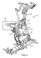
Figure 1 illustrates a side view of a landing gear system in accordance with the present disclosure; and -
Figure 2 illustrates a side view of a shock strut assembly in accordance with the present disclosure; and -
Figure 3 illustrates a cross sectional view of a shock strut assembly in accordance with the present disclosure. - The detailed description of embodiments herein makes reference to the accompanying drawings, which show embodiments by way of illustration. While these embodiments are described in sufficient detail to enable those skilled in the art to practice the inventions, it should be understood that other embodiments may be realized and that logical and mechanical changes may be made without departing from the spirit and scope of the inventions. Thus, the detailed description herein is presented for purposes of illustration only and not for limitation. For example, any reference to singular includes plural embodiments, and any reference to more than one component or step may include a singular embodiment or step. Also, any reference to attached, fixed, connected or the like may include permanent, removable, temporary, partial, full and/or any other possible attachment option.
- Landing gear components (such as shock strut outer cylinders) of the present disclosure comprise improved pins and/or structural attachment portions. Specifically, pins comprising a cobalt alloy body and cobalt containing coating may provide improved tensile strength, shear strength and/or wear characteristics. Further, the improved properties of these pins may allow for the elimination of separate, machined bushings typically found in various joints of landing gear systems, which tends to reduce weight. As bushings typically include a lubricant such as grease for lubrication, the elimination of bushings also eliminates the need to monitor and maintain proper lubrication of the bushing, as designs of the present disclosure are more lubricious than previous designs.
- Accordingly, with reference to
Figure 1 , alanding gear 100 is illustrated.Landing gear 100 may comprise, for example, ashock strut assembly 102.Shock strut assembly 102 may comprise anouter cylinder 104. In various embodiments, as will be discussed further, a number of components oflanding gear 100 are removably coupled toouter cylinder 104.Outer cylinder 104 may comprise multiple structural attachment portions which are configured to engage with and couple one or more components oflanding gear 100 toouter cylinder 104. - In various embodiments,
outer cylinder 104 comprises a metal part body and one or more structural attachment portions. For example,outer cylinder 104 may comprise a number of structural attachment portions configured to engage with and removably couple various other components oflanding gear 100 toouter cylinder 104. Such structural attachment portions may be referred to generally as "pins," and may differ in size, shape, and configuration from one another. As will be discussed further, each pin may be configured to couple to a corresponding receptacle of a particular metal component oflanding gear 100. - With reference to
Figure 2 ,outer cylinder 104 may comprise one ormore pins 105. In various embodiments,pin 105 comprises asubstrate 130.Substrate 130 may comprise, for example, a cobalt alloy. In that regard,substrate 130 may be referred to as a cobalt substrate. In various embodiments,cobalt substrate 130 comprises an alloy of cobalt with chromium and/or molybdenum, such as a cobalt-chromium-molybdenum alloy. For example,cobalt substrate 130 may comprise Co-28Cr-6Mo, also known as Acube® 100, produced by Carpenter. In various embodiments,cobalt substrate 130 comprises at least 15% cobalt by weight. - In various embodiments,
substrate 130 provides improved strength and wear resistance. For example,pins comprising substrate 130 may be used on various parts that tend to experience fatigue over time, in place of conventional pins which comprise materials of decreased tensile strength, such as Al-Ni-Br and/or CuBe alloys. Further,pins comprising substrate 130 tend to improve corrosion resistance even in embodiments where asubstrate 130 does not have a coating. -
Pins 105 may, for example, be formed independently fromouter cylinder 104, and then secured toouter cylinder 104. For example,pins 105 may be welded to an outer surface ofouter cylinder 104. In other embodiments,pins 105 are integral toouter cylinder 104. - As will be discussed,
pins 105 may comprise pins configured to engage with and removably couple various components oflanding gear 100 toshock strut assembly 102. With reference toFigures 1 and2 ,pins 105 may comprise, for example, any of a drag brace pin, a lower pintle frame pin, and a torque link pin, among other pins. - With reference to
Figure 3 ,pins 105 may be configured to engage with acomplementary receptacle 107. For example, acomplementary receptacle 107 may be configured to receive, maintain connection with, and orient anindividual pin 105. In various embodiments,receptacle 107 comprises a portion of a component oflanding gear 100 to whichpin 105 engages to couple the component to shockstrut assembly 102. In various embodiments,outer cylinder 104 comprises one or more pins that are complementary to receptacles and/or joints of multiple components oflanding gear 100. The combination of apin 105 ofouter cylinder 104 and thecorresponding receptacle 107 of each component may be referred to as a joint. -
Receptacle 107 may comprise aninner surface 109 coated with acoating 140. In various embodiments, coating 140, for example, a cobalt containing coating applied to at least a portion ofinner surface 109. For example, coating 140 may comprise a cobalt containing coating. In various embodiments, coating 140 may comprise Nanovate™ cobalt phosphorous coating produced by Integran.Cobalt containing coating 140 may be electroplated ontoinner surface 109. However, any method of depositing one or more layers ofcobalt containing coating 140 toinner surface 109 ofcorresponding receptacle 107 is within the scope of the present disclosure. - In various embodiments, coating 140 provides enhanced wear resistance to
pins 105 ofouter cylinder 104 so as to reduce or eliminate the desirability of a bushing. For example, typical joints between a drag brace and an outer cylinder include a bushing positioned around the drag brace pin. In various embodiments, coating 140 reduces or eliminates the desirability for such a bushing.Complementary receptacles 107 comprisingcoating 140 may be particularly useful in joints where expensive anti-wear coatings are used, as well as joints which are difficult to lubricate. - As will be discussed,
receptacle 107 may comprise a portion of landing gear components including adrag brace 106, apintle frame 110, and atorque link 124, among other components oflanding gear 100. - With reference to
figure 1 ,landing gear 100 may further comprise, for example, adrag brace 106. In various embodiments,drag brace 106 is removably coupled toouter cylinder 104. For example,outer cylinder 104 may comprise adrag brace pin 108 configured to engage with a corresponding receptacle and/or joint ofdrag brace 106. - In various embodiments,
landing gear 100 may comprise apintle frame 110. For example,pintle frame 110 may removably coupleshock strut assembly 102 to anairframe 150.Outer cylinder 104 may comprise a lowerpintle frame pin 114. In such embodiments, lowerpintle frame pin 114 may engage with a complementary receptacle and/or joint ofpintle frame 110. - In various embodiments,
landing gear 100 further comprises one ormore torque links 124. For example,torque link 124 may removably couple to shockstrut assembly 102 and orient the assembly with relation to other components oflanding gear 100, including, for example, abogie beam 122.Outer cylinder 104 may comprise one or more torque link pins 112 capable of engaging with a corresponding receptacle and/or joint oftorque link 124. - Benefits, other advantages, and solutions to problems have been described herein with regard to specific embodiments. Furthermore, the connecting lines shown in the various figures contained herein are intended to represent exemplary functional relationships and/or physical couplings between the various elements. It should be noted that many alternative or additional functional relationships or physical connections may be present in a practical system. However, the benefits, advantages, solutions to problems, and any elements that may cause any benefit, advantage, or solution to occur or become more pronounced are not to be construed as critical, required, or essential features or elements of the inventions. The scope of the inventions is accordingly to be limited by nothing other than the appended claims, in which reference to an element in the singular is not intended to mean "one and only one" unless explicitly so stated, but rather "one or more." Moreover, where a phrase similar to "at least one of A, B, or C" is used in the claims, it is intended that the phrase be interpreted to mean that A alone may be present in an embodiment, B alone may be present in an embodiment, C alone may be present in an embodiment, or that any combination of the elements A, B and C may be present in a single embodiment; for example, A and B, A and C, B and C, or A and B and C. Different cross-hatching is used throughout the figures to denote different parts but not necessarily to denote the same or different materials.
- Systems, methods and apparatus are provided herein. In the detailed description herein, references to "one embodiment," "an embodiment," "an example embodiment," etc., indicate that the embodiment described may include a particular feature, structure, or characteristic, but every embodiment may not necessarily include the particular feature, structure, or characteristic. Moreover, such phrases are not necessarily referring to the same embodiment. Further, when a particular feature, structure, or characteristic is described in connection with an embodiment, it is submitted that it is within the knowledge of one skilled in the art to affect such feature, structure, or characteristic in connection with other embodiments whether or not explicitly described. After reading the description, it will be apparent to one skilled in the relevant art(s) how to implement the disclosure in alternative embodiments.
- Furthermore, no element, component, or method step in the present disclosure is intended to be dedicated to the public regardless of whether the element, component, or method step is explicitly recited in the claims. No claim element herein is to be construed under the provisions of 35 U.S.C. 112(f), unless the element is expressly recited using the phrase "means for." As used herein, the terms "comprises," "comprising," or any other variation thereof, are intended to cover a non-exclusive inclusion, such that a process, method, article, or apparatus that comprises a list of elements does not include only those elements but may include other elements not expressly listed or inherent to such process, method, article, or apparatus.
Claims (11)
- A shock strut of a landing gear system, comprising:an outer cylinder (104) having a structural attachment portion comprising a cobalt substrate (130) and configured to engage with a complementary receptacle (107) comprising a cobalt containing coating (140) over at least a portion of an inner surface (109).
- The shock strut of claim 1, wherein the cobalt substrate (130) of the structural attachment portion comprises a cobalt-chromium-molybdenum alloy.
- The shock strut of claim 2, wherein the cobalt-chromium-molybdenum alloy comprises Co-28Cr-6Mo.
- The shock strut of claim 1, wherein the structural attachment portion comprises Co-28Cr-6Mo.
- The shock strut of any preceding claim, wherein the structural attachment portion comprises at least one of a drag brace pin (108), a torque link pin (112), or a lower pintle frame pin (114).
- A landing gear system, comprising:the shock strut of any preceding claim; anda metal component having a complementary receptacle (107) comprising a cobalt containing coating (140) over at least a portion of an inner surface (109) and configured to be removably coupled to the structural attachment portion of the outer cylinder (104).
- The landing gear system of claim 6, wherein the metal component comprises a torque link (124) configured to engage with a/the torque link pin (112).
- The landing gear system of claim 6 or 7, wherein the structural attachment portion comprises a/the lower pintle frame pin (114) and wherein the metal component comprises a pintle frame (110) configured to engage with the lower pintle frame pin (114).
- The landing gear system of claim 6, 7 or 8, wherein the structural attachment portion comprises a/the drag brace pin (108), and wherein the metal component comprises a drag brace (106) configured to engage with the drag brace pin (108).
- The landing gear system of any of claims 6 to 9, wherein the cobalt containing coating (140) is an electroplated coating on the inner surface (109) of the complementary receptacle (107).
- The landing gear system of claims 6 to 10, wherein the complementary receptacle (107) is integral to the metal component of the landing gear system.
Applications Claiming Priority (1)
| Application Number | Priority Date | Filing Date | Title |
|---|---|---|---|
| US14/497,662 US9452827B2 (en) | 2014-09-26 | 2014-09-26 | Landing gear components having improved joints |
Publications (2)
| Publication Number | Publication Date |
|---|---|
| EP3000728A1 true EP3000728A1 (en) | 2016-03-30 |
| EP3000728B1 EP3000728B1 (en) | 2018-11-28 |
Family
ID=54249307
Family Applications (1)
| Application Number | Title | Priority Date | Filing Date |
|---|---|---|---|
| EP15186603.5A Active EP3000728B1 (en) | 2014-09-26 | 2015-09-24 | Landing gear components having improved joints |
Country Status (2)
| Country | Link |
|---|---|
| US (1) | US9452827B2 (en) |
| EP (1) | EP3000728B1 (en) |
Cited By (1)
| Publication number | Priority date | Publication date | Assignee | Title |
|---|---|---|---|---|
| CN112173084A (en) * | 2020-09-25 | 2021-01-05 | 中国直升机设计研究所 | Retractable main landing gear bearing structure of unmanned high-speed helicopter and design method thereof |
Families Citing this family (2)
| Publication number | Priority date | Publication date | Assignee | Title |
|---|---|---|---|---|
| US10577128B2 (en) | 2018-03-30 | 2020-03-03 | The Boeing Company | Health monitoring of aircraft landing gear mechanical structures |
| CN115492857A (en) * | 2022-09-20 | 2022-12-20 | 苏州铂源航天航空新材料有限公司 | Built-in coupling silicon-manganese alloy shaft sleeve of aircraft landing gear |
Citations (5)
| Publication number | Priority date | Publication date | Assignee | Title |
|---|---|---|---|---|
| US3356542A (en) * | 1967-04-10 | 1967-12-05 | Du Pont | Cobalt-nickel base alloys containing chromium and molybdenum |
| EP1195446A1 (en) * | 2000-10-04 | 2002-04-10 | General Electric Company | Ni based superalloy and its use as gas turbine disks, shafts, and impellers |
| US20040236433A1 (en) * | 2003-05-23 | 2004-11-25 | Kennedy Richard L. | Cobalt alloys, methods of making cobalt alloys, and implants and articles of manufacture made therefrom |
| WO2006071263A2 (en) * | 2004-06-18 | 2006-07-06 | Goodrich Corporation | Retractable articulated landing gear |
| WO2014101772A1 (en) * | 2012-12-26 | 2014-07-03 | Matrix Metals Llc | Cobalt-chromium-molybdenum alloy with high wear resistance |
Family Cites Families (14)
| Publication number | Priority date | Publication date | Assignee | Title |
|---|---|---|---|---|
| US1759652A (en) * | 1929-06-29 | 1930-05-20 | Loening Grover | Retractable landing gear |
| US4359199A (en) * | 1979-12-05 | 1982-11-16 | The United States Of America As Represented By The Secretary Of The Air Force | Soft landing gear |
| JPS6057519B2 (en) * | 1981-08-20 | 1985-12-16 | 住友金属工業株式会社 | Oil country tubular joint with excellent seizure resistance and its manufacturing method |
| US9138805B2 (en) * | 2002-03-06 | 2015-09-22 | Deere & Company | Method for applying wear resistant coating to mechanical face seal |
| GB0416740D0 (en) * | 2004-07-27 | 2004-09-01 | Messier Dowty Ltd | Aircraft landing gear |
| EP1655091A1 (en) * | 2004-11-09 | 2006-05-10 | Siemens Aktiengesellschaft | Method for electrolytically processing a workpiece and workpiece having a through hole |
| MX2009008163A (en) * | 2007-02-02 | 2009-08-12 | Messier Dowty Inc | Self lubricating pin assembly. |
| US8034197B2 (en) * | 2007-06-19 | 2011-10-11 | Carnegie Mellon University | Ultra-high strength stainless steels |
| US8545994B2 (en) * | 2009-06-02 | 2013-10-01 | Integran Technologies Inc. | Electrodeposited metallic materials comprising cobalt |
| US8367217B2 (en) * | 2009-06-02 | 2013-02-05 | Integran Technologies, Inc. | Electrodeposited metallic-materials comprising cobalt on iron-alloy substrates with enhanced fatigue performance |
| GB0922488D0 (en) * | 2009-12-23 | 2010-02-03 | Advanced Interactive Materials | Improvements in or relating to hot isostatic pressing |
| US10131419B2 (en) * | 2010-10-15 | 2018-11-20 | Goodrich Corporation | Systems and methods for detecting landing gear ground loads |
| US20130156555A1 (en) * | 2011-12-15 | 2013-06-20 | General Electric Company | Braze materials, brazing processes, and components with wear-resistant coatings formed thereby |
| US20160289800A1 (en) * | 2012-08-28 | 2016-10-06 | Questek Innovations Llc | Cobalt alloys |
-
2014
- 2014-09-26 US US14/497,662 patent/US9452827B2/en active Active
-
2015
- 2015-09-24 EP EP15186603.5A patent/EP3000728B1/en active Active
Patent Citations (5)
| Publication number | Priority date | Publication date | Assignee | Title |
|---|---|---|---|---|
| US3356542A (en) * | 1967-04-10 | 1967-12-05 | Du Pont | Cobalt-nickel base alloys containing chromium and molybdenum |
| EP1195446A1 (en) * | 2000-10-04 | 2002-04-10 | General Electric Company | Ni based superalloy and its use as gas turbine disks, shafts, and impellers |
| US20040236433A1 (en) * | 2003-05-23 | 2004-11-25 | Kennedy Richard L. | Cobalt alloys, methods of making cobalt alloys, and implants and articles of manufacture made therefrom |
| WO2006071263A2 (en) * | 2004-06-18 | 2006-07-06 | Goodrich Corporation | Retractable articulated landing gear |
| WO2014101772A1 (en) * | 2012-12-26 | 2014-07-03 | Matrix Metals Llc | Cobalt-chromium-molybdenum alloy with high wear resistance |
Non-Patent Citations (1)
| Title |
|---|
| "Material Specification Cobalt Chrome Alloy Co28Cr6Mo", 3 September 2013 (2013-09-03), XP055241839, Retrieved from the Internet <URL:http://www.3trpd.co.uk/wp-content/uploads/2013/03/cobalt-chrome-alloy-co28-cr6mo-2012.pdf> [retrieved on 20160115] * |
Cited By (1)
| Publication number | Priority date | Publication date | Assignee | Title |
|---|---|---|---|---|
| CN112173084A (en) * | 2020-09-25 | 2021-01-05 | 中国直升机设计研究所 | Retractable main landing gear bearing structure of unmanned high-speed helicopter and design method thereof |
Also Published As
| Publication number | Publication date |
|---|---|
| US20160090172A1 (en) | 2016-03-31 |
| US9452827B2 (en) | 2016-09-27 |
| EP3000728B1 (en) | 2018-11-28 |
Similar Documents
| Publication | Publication Date | Title |
|---|---|---|
| US10890211B2 (en) | Dynamic bearing | |
| US9452827B2 (en) | Landing gear components having improved joints | |
| EP2931519B1 (en) | Plain bearing composite material | |
| US8764034B2 (en) | Steering axle assembly with self-lubricated bearings | |
| US10933981B2 (en) | Aerodynamic noise reducing thin-skin landing gear structures and manufacturing techniques | |
| JP4680446B2 (en) | Oil well steel pipe fittings | |
| US20100269629A1 (en) | Low friction slotted bearing and link apparatus | |
| EP3222859A1 (en) | Damage tolerant and fail-safe (dtfs) high strength preloaded pin assembly | |
| EP1288512A2 (en) | Truck pivot joint bearing and method of lubricating | |
| AU2013348390B2 (en) | Modular axle shaft assemblies for use with racing vehicles and other vehicles | |
| US20220048614A1 (en) | Landing gear support | |
| DE3246935C2 (en) | ||
| EP2993256A1 (en) | Nickel repair of titanium surfaces | |
| DE102017205933A1 (en) | Flange hub for wheel bearings | |
| DE102010038260A1 (en) | Method for producing a composite beam axle in mixed construction | |
| DE102013225334A1 (en) | Handlebar of a chassis for motor vehicles | |
| CN110397654B (en) | Aircraft assembly | |
| EP1904259A1 (en) | Method for the production of a composite component comprising two component sections with a basic adhesive nickel layer located between the two component sections | |
| US9790613B2 (en) | Aluminum alloy anodization | |
| EP4159474A1 (en) | Impeller component for an impeller of a two-wheeled vehicle which is operated at least partially by muscle force, and impeller | |
| DE102014106470A1 (en) | Bearing bush for a chassis or transmission component of a motor vehicle | |
| GB2493744A (en) | Improved Aircraft Landing Gear Assembly and Method of Manufacture | |
| DE102017131165A1 (en) | Mobile crane chassis | |
| DE102018217524A1 (en) | Flange inner ring for wheel hub bearings | |
| Reid | ASC1. 3 Innovative Bushed Joint Technology for Durability and Metallic/Composite Structural Assembly |
Legal Events
| Date | Code | Title | Description |
|---|---|---|---|
| PUAI | Public reference made under article 153(3) epc to a published international application that has entered the european phase |
Free format text: ORIGINAL CODE: 0009012 |
|
| AK | Designated contracting states |
Kind code of ref document: A1 Designated state(s): AL AT BE BG CH CY CZ DE DK EE ES FI FR GB GR HR HU IE IS IT LI LT LU LV MC MK MT NL NO PL PT RO RS SE SI SK SM TR |
|
| AX | Request for extension of the european patent |
Extension state: BA ME |
|
| 17P | Request for examination filed |
Effective date: 20160928 |
|
| RBV | Designated contracting states (corrected) |
Designated state(s): AL AT BE BG CH CY CZ DE DK EE ES FI FR GB GR HR HU IE IS IT LI LT LU LV MC MK MT NL NO PL PT RO RS SE SI SK SM TR |
|
| STAA | Information on the status of an ep patent application or granted ep patent |
Free format text: STATUS: EXAMINATION IS IN PROGRESS |
|
| 17Q | First examination report despatched |
Effective date: 20170202 |
|
| GRAP | Despatch of communication of intention to grant a patent |
Free format text: ORIGINAL CODE: EPIDOSNIGR1 |
|
| STAA | Information on the status of an ep patent application or granted ep patent |
Free format text: STATUS: GRANT OF PATENT IS INTENDED |
|
| INTG | Intention to grant announced |
Effective date: 20180607 |
|
| GRAS | Grant fee paid |
Free format text: ORIGINAL CODE: EPIDOSNIGR3 |
|
| GRAA | (expected) grant |
Free format text: ORIGINAL CODE: 0009210 |
|
| STAA | Information on the status of an ep patent application or granted ep patent |
Free format text: STATUS: THE PATENT HAS BEEN GRANTED |
|
| AK | Designated contracting states |
Kind code of ref document: B1 Designated state(s): AL AT BE BG CH CY CZ DE DK EE ES FI FR GB GR HR HU IE IS IT LI LT LU LV MC MK MT NL NO PL PT RO RS SE SI SK SM TR |
|
| REG | Reference to a national code |
Ref country code: CH Ref legal event code: EP |
|
| REG | Reference to a national code |
Ref country code: AT Ref legal event code: REF Ref document number: 1069922 Country of ref document: AT Kind code of ref document: T Effective date: 20181215 |
|
| REG | Reference to a national code |
Ref country code: IE Ref legal event code: FG4D |
|
| REG | Reference to a national code |
Ref country code: DE Ref legal event code: R096 Ref document number: 602015020306 Country of ref document: DE |
|
| REG | Reference to a national code |
Ref country code: NL Ref legal event code: MP Effective date: 20181128 |
|
| REG | Reference to a national code |
Ref country code: LT Ref legal event code: MG4D |
|
| REG | Reference to a national code |
Ref country code: AT Ref legal event code: MK05 Ref document number: 1069922 Country of ref document: AT Kind code of ref document: T Effective date: 20181128 |
|
| PG25 | Lapsed in a contracting state [announced via postgrant information from national office to epo] |
Ref country code: FI Free format text: LAPSE BECAUSE OF FAILURE TO SUBMIT A TRANSLATION OF THE DESCRIPTION OR TO PAY THE FEE WITHIN THE PRESCRIBED TIME-LIMIT Effective date: 20181128 Ref country code: AT Free format text: LAPSE BECAUSE OF FAILURE TO SUBMIT A TRANSLATION OF THE DESCRIPTION OR TO PAY THE FEE WITHIN THE PRESCRIBED TIME-LIMIT Effective date: 20181128 Ref country code: LV Free format text: LAPSE BECAUSE OF FAILURE TO SUBMIT A TRANSLATION OF THE DESCRIPTION OR TO PAY THE FEE WITHIN THE PRESCRIBED TIME-LIMIT Effective date: 20181128 Ref country code: NO Free format text: LAPSE BECAUSE OF FAILURE TO SUBMIT A TRANSLATION OF THE DESCRIPTION OR TO PAY THE FEE WITHIN THE PRESCRIBED TIME-LIMIT Effective date: 20190228 Ref country code: HR Free format text: LAPSE BECAUSE OF FAILURE TO SUBMIT A TRANSLATION OF THE DESCRIPTION OR TO PAY THE FEE WITHIN THE PRESCRIBED TIME-LIMIT Effective date: 20181128 Ref country code: BG Free format text: LAPSE BECAUSE OF FAILURE TO SUBMIT A TRANSLATION OF THE DESCRIPTION OR TO PAY THE FEE WITHIN THE PRESCRIBED TIME-LIMIT Effective date: 20190228 Ref country code: IS Free format text: LAPSE BECAUSE OF FAILURE TO SUBMIT A TRANSLATION OF THE DESCRIPTION OR TO PAY THE FEE WITHIN THE PRESCRIBED TIME-LIMIT Effective date: 20190328 Ref country code: LT Free format text: LAPSE BECAUSE OF FAILURE TO SUBMIT A TRANSLATION OF THE DESCRIPTION OR TO PAY THE FEE WITHIN THE PRESCRIBED TIME-LIMIT Effective date: 20181128 Ref country code: ES Free format text: LAPSE BECAUSE OF FAILURE TO SUBMIT A TRANSLATION OF THE DESCRIPTION OR TO PAY THE FEE WITHIN THE PRESCRIBED TIME-LIMIT Effective date: 20181128 |
|
| PG25 | Lapsed in a contracting state [announced via postgrant information from national office to epo] |
Ref country code: AL Free format text: LAPSE BECAUSE OF FAILURE TO SUBMIT A TRANSLATION OF THE DESCRIPTION OR TO PAY THE FEE WITHIN THE PRESCRIBED TIME-LIMIT Effective date: 20181128 Ref country code: PT Free format text: LAPSE BECAUSE OF FAILURE TO SUBMIT A TRANSLATION OF THE DESCRIPTION OR TO PAY THE FEE WITHIN THE PRESCRIBED TIME-LIMIT Effective date: 20190328 Ref country code: GR Free format text: LAPSE BECAUSE OF FAILURE TO SUBMIT A TRANSLATION OF THE DESCRIPTION OR TO PAY THE FEE WITHIN THE PRESCRIBED TIME-LIMIT Effective date: 20190301 Ref country code: SE Free format text: LAPSE BECAUSE OF FAILURE TO SUBMIT A TRANSLATION OF THE DESCRIPTION OR TO PAY THE FEE WITHIN THE PRESCRIBED TIME-LIMIT Effective date: 20181128 Ref country code: RS Free format text: LAPSE BECAUSE OF FAILURE TO SUBMIT A TRANSLATION OF THE DESCRIPTION OR TO PAY THE FEE WITHIN THE PRESCRIBED TIME-LIMIT Effective date: 20181128 |
|
| PG25 | Lapsed in a contracting state [announced via postgrant information from national office to epo] |
Ref country code: NL Free format text: LAPSE BECAUSE OF FAILURE TO SUBMIT A TRANSLATION OF THE DESCRIPTION OR TO PAY THE FEE WITHIN THE PRESCRIBED TIME-LIMIT Effective date: 20181128 |
|
| PG25 | Lapsed in a contracting state [announced via postgrant information from national office to epo] |
Ref country code: CZ Free format text: LAPSE BECAUSE OF FAILURE TO SUBMIT A TRANSLATION OF THE DESCRIPTION OR TO PAY THE FEE WITHIN THE PRESCRIBED TIME-LIMIT Effective date: 20181128 Ref country code: IT Free format text: LAPSE BECAUSE OF FAILURE TO SUBMIT A TRANSLATION OF THE DESCRIPTION OR TO PAY THE FEE WITHIN THE PRESCRIBED TIME-LIMIT Effective date: 20181128 Ref country code: DK Free format text: LAPSE BECAUSE OF FAILURE TO SUBMIT A TRANSLATION OF THE DESCRIPTION OR TO PAY THE FEE WITHIN THE PRESCRIBED TIME-LIMIT Effective date: 20181128 Ref country code: PL Free format text: LAPSE BECAUSE OF FAILURE TO SUBMIT A TRANSLATION OF THE DESCRIPTION OR TO PAY THE FEE WITHIN THE PRESCRIBED TIME-LIMIT Effective date: 20181128 |
|
| REG | Reference to a national code |
Ref country code: DE Ref legal event code: R097 Ref document number: 602015020306 Country of ref document: DE |
|
| PG25 | Lapsed in a contracting state [announced via postgrant information from national office to epo] |
Ref country code: EE Free format text: LAPSE BECAUSE OF FAILURE TO SUBMIT A TRANSLATION OF THE DESCRIPTION OR TO PAY THE FEE WITHIN THE PRESCRIBED TIME-LIMIT Effective date: 20181128 Ref country code: SM Free format text: LAPSE BECAUSE OF FAILURE TO SUBMIT A TRANSLATION OF THE DESCRIPTION OR TO PAY THE FEE WITHIN THE PRESCRIBED TIME-LIMIT Effective date: 20181128 Ref country code: SK Free format text: LAPSE BECAUSE OF FAILURE TO SUBMIT A TRANSLATION OF THE DESCRIPTION OR TO PAY THE FEE WITHIN THE PRESCRIBED TIME-LIMIT Effective date: 20181128 Ref country code: RO Free format text: LAPSE BECAUSE OF FAILURE TO SUBMIT A TRANSLATION OF THE DESCRIPTION OR TO PAY THE FEE WITHIN THE PRESCRIBED TIME-LIMIT Effective date: 20181128 |
|
| PLBE | No opposition filed within time limit |
Free format text: ORIGINAL CODE: 0009261 |
|
| STAA | Information on the status of an ep patent application or granted ep patent |
Free format text: STATUS: NO OPPOSITION FILED WITHIN TIME LIMIT |
|
| PG25 | Lapsed in a contracting state [announced via postgrant information from national office to epo] |
Ref country code: SI Free format text: LAPSE BECAUSE OF FAILURE TO SUBMIT A TRANSLATION OF THE DESCRIPTION OR TO PAY THE FEE WITHIN THE PRESCRIBED TIME-LIMIT Effective date: 20181128 |
|
| 26N | No opposition filed |
Effective date: 20190829 |
|
| PG25 | Lapsed in a contracting state [announced via postgrant information from national office to epo] |
Ref country code: TR Free format text: LAPSE BECAUSE OF FAILURE TO SUBMIT A TRANSLATION OF THE DESCRIPTION OR TO PAY THE FEE WITHIN THE PRESCRIBED TIME-LIMIT Effective date: 20181128 |
|
| PG25 | Lapsed in a contracting state [announced via postgrant information from national office to epo] |
Ref country code: MC Free format text: LAPSE BECAUSE OF FAILURE TO SUBMIT A TRANSLATION OF THE DESCRIPTION OR TO PAY THE FEE WITHIN THE PRESCRIBED TIME-LIMIT Effective date: 20181128 |
|
| REG | Reference to a national code |
Ref country code: CH Ref legal event code: PL |
|
| PG25 | Lapsed in a contracting state [announced via postgrant information from national office to epo] |
Ref country code: LI Free format text: LAPSE BECAUSE OF NON-PAYMENT OF DUE FEES Effective date: 20190930 Ref country code: LU Free format text: LAPSE BECAUSE OF NON-PAYMENT OF DUE FEES Effective date: 20190924 Ref country code: IE Free format text: LAPSE BECAUSE OF NON-PAYMENT OF DUE FEES Effective date: 20190924 Ref country code: CH Free format text: LAPSE BECAUSE OF NON-PAYMENT OF DUE FEES Effective date: 20190930 |
|
| REG | Reference to a national code |
Ref country code: BE Ref legal event code: MM Effective date: 20190930 |
|
| PG25 | Lapsed in a contracting state [announced via postgrant information from national office to epo] |
Ref country code: BE Free format text: LAPSE BECAUSE OF NON-PAYMENT OF DUE FEES Effective date: 20190930 |
|
| GBPC | Gb: european patent ceased through non-payment of renewal fee |
Effective date: 20190924 |
|
| PG25 | Lapsed in a contracting state [announced via postgrant information from national office to epo] |
Ref country code: GB Free format text: LAPSE BECAUSE OF NON-PAYMENT OF DUE FEES Effective date: 20190924 |
|
| PG25 | Lapsed in a contracting state [announced via postgrant information from national office to epo] |
Ref country code: CY Free format text: LAPSE BECAUSE OF FAILURE TO SUBMIT A TRANSLATION OF THE DESCRIPTION OR TO PAY THE FEE WITHIN THE PRESCRIBED TIME-LIMIT Effective date: 20181128 |
|
| PG25 | Lapsed in a contracting state [announced via postgrant information from national office to epo] |
Ref country code: HU Free format text: LAPSE BECAUSE OF FAILURE TO SUBMIT A TRANSLATION OF THE DESCRIPTION OR TO PAY THE FEE WITHIN THE PRESCRIBED TIME-LIMIT; INVALID AB INITIO Effective date: 20150924 Ref country code: MT Free format text: LAPSE BECAUSE OF FAILURE TO SUBMIT A TRANSLATION OF THE DESCRIPTION OR TO PAY THE FEE WITHIN THE PRESCRIBED TIME-LIMIT Effective date: 20181128 |
|
| PG25 | Lapsed in a contracting state [announced via postgrant information from national office to epo] |
Ref country code: MK Free format text: LAPSE BECAUSE OF FAILURE TO SUBMIT A TRANSLATION OF THE DESCRIPTION OR TO PAY THE FEE WITHIN THE PRESCRIBED TIME-LIMIT Effective date: 20181128 |
|
| P01 | Opt-out of the competence of the unified patent court (upc) registered |
Effective date: 20230522 |
|
| PGFP | Annual fee paid to national office [announced via postgrant information from national office to epo] |
Ref country code: DE Payment date: 20250820 Year of fee payment: 11 |
|
| PGFP | Annual fee paid to national office [announced via postgrant information from national office to epo] |
Ref country code: FR Payment date: 20250820 Year of fee payment: 11 |