EP3000681A1 - Stop position determining device for transport vehicle and transport vehicle with the same - Google Patents
Stop position determining device for transport vehicle and transport vehicle with the same Download PDFInfo
- Publication number
- EP3000681A1 EP3000681A1 EP15182943.9A EP15182943A EP3000681A1 EP 3000681 A1 EP3000681 A1 EP 3000681A1 EP 15182943 A EP15182943 A EP 15182943A EP 3000681 A1 EP3000681 A1 EP 3000681A1
- Authority
- EP
- European Patent Office
- Prior art keywords
- bund
- transport vehicle
- stop position
- traveling
- module
- Prior art date
- Legal status (The legal status is an assumption and is not a legal conclusion. Google has not performed a legal analysis and makes no representation as to the accuracy of the status listed.)
- Granted
Links
- 238000004364 calculation method Methods 0.000 claims abstract description 34
- 238000001514 detection method Methods 0.000 description 28
- 230000032258 transport Effects 0.000 description 23
- 238000004891 communication Methods 0.000 description 17
- 238000007599 discharging Methods 0.000 description 14
- 238000013500 data storage Methods 0.000 description 8
- 238000010586 diagram Methods 0.000 description 8
- 230000006870 function Effects 0.000 description 8
- 230000009471 action Effects 0.000 description 7
- 238000010276 construction Methods 0.000 description 7
- 239000004576 sand Substances 0.000 description 7
- 240000004050 Pentaglottis sempervirens Species 0.000 description 6
- 235000004522 Pentaglottis sempervirens Nutrition 0.000 description 6
- 230000008859 change Effects 0.000 description 6
- 238000005065 mining Methods 0.000 description 6
- 230000004044 response Effects 0.000 description 5
- 238000000034 method Methods 0.000 description 4
- 238000012545 processing Methods 0.000 description 4
- 238000013075 data extraction Methods 0.000 description 3
- KNMAVSAGTYIFJF-UHFFFAOYSA-N 1-[2-[(2-hydroxy-3-phenoxypropyl)amino]ethylamino]-3-phenoxypropan-2-ol;dihydrochloride Chemical compound Cl.Cl.C=1C=CC=CC=1OCC(O)CNCCNCC(O)COC1=CC=CC=C1 KNMAVSAGTYIFJF-UHFFFAOYSA-N 0.000 description 2
- 230000001276 controlling effect Effects 0.000 description 2
- 238000005516 engineering process Methods 0.000 description 2
- 238000012986 modification Methods 0.000 description 2
- 230000004048 modification Effects 0.000 description 2
- 230000004075 alteration Effects 0.000 description 1
- 238000009412 basement excavation Methods 0.000 description 1
- 238000006243 chemical reaction Methods 0.000 description 1
- 230000002596 correlated effect Effects 0.000 description 1
- 230000000875 corresponding effect Effects 0.000 description 1
- 239000004973 liquid crystal related substance Substances 0.000 description 1
- 239000000463 material Substances 0.000 description 1
- 238000005259 measurement Methods 0.000 description 1
- 230000003287 optical effect Effects 0.000 description 1
- 238000002360 preparation method Methods 0.000 description 1
- 230000008569 process Effects 0.000 description 1
- 230000000452 restraining effect Effects 0.000 description 1
- 239000000725 suspension Substances 0.000 description 1
- 230000000007 visual effect Effects 0.000 description 1
Images


Classifications
-
- E—FIXED CONSTRUCTIONS
- E01—CONSTRUCTION OF ROADS, RAILWAYS, OR BRIDGES
- E01C—CONSTRUCTION OF, OR SURFACES FOR, ROADS, SPORTS GROUNDS, OR THE LIKE; MACHINES OR AUXILIARY TOOLS FOR CONSTRUCTION OR REPAIR
- E01C19/00—Machines, tools or auxiliary devices for preparing or distributing paving materials, for working the placed materials, or for forming, consolidating, or finishing the paving
- E01C19/004—Devices for guiding or controlling the machines along a predetermined path
-
- B—PERFORMING OPERATIONS; TRANSPORTING
- B60—VEHICLES IN GENERAL
- B60T—VEHICLE BRAKE CONTROL SYSTEMS OR PARTS THEREOF; BRAKE CONTROL SYSTEMS OR PARTS THEREOF, IN GENERAL; ARRANGEMENT OF BRAKING ELEMENTS ON VEHICLES IN GENERAL; PORTABLE DEVICES FOR PREVENTING UNWANTED MOVEMENT OF VEHICLES; VEHICLE MODIFICATIONS TO FACILITATE COOLING OF BRAKES
- B60T7/00—Brake-action initiating means
- B60T7/12—Brake-action initiating means for automatic initiation; for initiation not subject to will of driver or passenger
- B60T7/22—Brake-action initiating means for automatic initiation; for initiation not subject to will of driver or passenger initiated by contact of vehicle, e.g. bumper, with an external object, e.g. another vehicle, or by means of contactless obstacle detectors mounted on the vehicle
-
- B—PERFORMING OPERATIONS; TRANSPORTING
- B60—VEHICLES IN GENERAL
- B60W—CONJOINT CONTROL OF VEHICLE SUB-UNITS OF DIFFERENT TYPE OR DIFFERENT FUNCTION; CONTROL SYSTEMS SPECIALLY ADAPTED FOR HYBRID VEHICLES; ROAD VEHICLE DRIVE CONTROL SYSTEMS FOR PURPOSES NOT RELATED TO THE CONTROL OF A PARTICULAR SUB-UNIT
- B60W30/00—Purposes of road vehicle drive control systems not related to the control of a particular sub-unit, e.g. of systems using conjoint control of vehicle sub-units
- B60W30/18—Propelling the vehicle
- B60W30/18009—Propelling the vehicle related to particular drive situations
- B60W30/18036—Reversing
-
- B—PERFORMING OPERATIONS; TRANSPORTING
- B60—VEHICLES IN GENERAL
- B60W—CONJOINT CONTROL OF VEHICLE SUB-UNITS OF DIFFERENT TYPE OR DIFFERENT FUNCTION; CONTROL SYSTEMS SPECIALLY ADAPTED FOR HYBRID VEHICLES; ROAD VEHICLE DRIVE CONTROL SYSTEMS FOR PURPOSES NOT RELATED TO THE CONTROL OF A PARTICULAR SUB-UNIT
- B60W30/00—Purposes of road vehicle drive control systems not related to the control of a particular sub-unit, e.g. of systems using conjoint control of vehicle sub-units
- B60W30/18—Propelling the vehicle
- B60W30/18009—Propelling the vehicle related to particular drive situations
- B60W30/181—Preparing for stopping
-
- B—PERFORMING OPERATIONS; TRANSPORTING
- B60—VEHICLES IN GENERAL
- B60W—CONJOINT CONTROL OF VEHICLE SUB-UNITS OF DIFFERENT TYPE OR DIFFERENT FUNCTION; CONTROL SYSTEMS SPECIALLY ADAPTED FOR HYBRID VEHICLES; ROAD VEHICLE DRIVE CONTROL SYSTEMS FOR PURPOSES NOT RELATED TO THE CONTROL OF A PARTICULAR SUB-UNIT
- B60W30/00—Purposes of road vehicle drive control systems not related to the control of a particular sub-unit, e.g. of systems using conjoint control of vehicle sub-units
- B60W30/18—Propelling the vehicle
- B60W30/18009—Propelling the vehicle related to particular drive situations
- B60W30/18109—Braking
-
- B—PERFORMING OPERATIONS; TRANSPORTING
- B60—VEHICLES IN GENERAL
- B60W—CONJOINT CONTROL OF VEHICLE SUB-UNITS OF DIFFERENT TYPE OR DIFFERENT FUNCTION; CONTROL SYSTEMS SPECIALLY ADAPTED FOR HYBRID VEHICLES; ROAD VEHICLE DRIVE CONTROL SYSTEMS FOR PURPOSES NOT RELATED TO THE CONTROL OF A PARTICULAR SUB-UNIT
- B60W40/00—Estimation or calculation of non-directly measurable driving parameters for road vehicle drive control systems not related to the control of a particular sub unit, e.g. by using mathematical models
- B60W40/02—Estimation or calculation of non-directly measurable driving parameters for road vehicle drive control systems not related to the control of a particular sub unit, e.g. by using mathematical models related to ambient conditions
- B60W40/06—Road conditions
-
- E—FIXED CONSTRUCTIONS
- E02—HYDRAULIC ENGINEERING; FOUNDATIONS; SOIL SHIFTING
- E02F—DREDGING; SOIL-SHIFTING
- E02F3/00—Dredgers; Soil-shifting machines
- E02F3/04—Dredgers; Soil-shifting machines mechanically-driven
- E02F3/76—Graders, bulldozers, or the like with scraper plates or ploughshare-like elements; Levelling scarifying devices
- E02F3/80—Component parts
- E02F3/84—Drives or control devices therefor, e.g. hydraulic drive systems
- E02F3/841—Devices for controlling and guiding the whole machine, e.g. by feeler elements and reference lines placed exteriorly of the machine
-
- E—FIXED CONSTRUCTIONS
- E02—HYDRAULIC ENGINEERING; FOUNDATIONS; SOIL SHIFTING
- E02F—DREDGING; SOIL-SHIFTING
- E02F9/00—Component parts of dredgers or soil-shifting machines, not restricted to one of the kinds covered by groups E02F3/00 - E02F7/00
- E02F9/20—Drives; Control devices
- E02F9/2025—Particular purposes of control systems not otherwise provided for
- E02F9/2045—Guiding machines along a predetermined path
-
- G—PHYSICS
- G05—CONTROLLING; REGULATING
- G05D—SYSTEMS FOR CONTROLLING OR REGULATING NON-ELECTRIC VARIABLES
- G05D1/00—Control of position, course, altitude or attitude of land, water, air or space vehicles, e.g. using automatic pilots
- G05D1/02—Control of position or course in two dimensions
- G05D1/021—Control of position or course in two dimensions specially adapted to land vehicles
- G05D1/0212—Control of position or course in two dimensions specially adapted to land vehicles with means for defining a desired trajectory
- G05D1/0225—Control of position or course in two dimensions specially adapted to land vehicles with means for defining a desired trajectory involving docking at a fixed facility, e.g. base station or loading bay
-
- B—PERFORMING OPERATIONS; TRANSPORTING
- B60—VEHICLES IN GENERAL
- B60T—VEHICLE BRAKE CONTROL SYSTEMS OR PARTS THEREOF; BRAKE CONTROL SYSTEMS OR PARTS THEREOF, IN GENERAL; ARRANGEMENT OF BRAKING ELEMENTS ON VEHICLES IN GENERAL; PORTABLE DEVICES FOR PREVENTING UNWANTED MOVEMENT OF VEHICLES; VEHICLE MODIFICATIONS TO FACILITATE COOLING OF BRAKES
- B60T2201/00—Particular use of vehicle brake systems; Special systems using also the brakes; Special software modules within the brake system controller
- B60T2201/02—Active or adaptive cruise control system; Distance control
- B60T2201/022—Collision avoidance systems
-
- B—PERFORMING OPERATIONS; TRANSPORTING
- B60—VEHICLES IN GENERAL
- B60W—CONJOINT CONTROL OF VEHICLE SUB-UNITS OF DIFFERENT TYPE OR DIFFERENT FUNCTION; CONTROL SYSTEMS SPECIALLY ADAPTED FOR HYBRID VEHICLES; ROAD VEHICLE DRIVE CONTROL SYSTEMS FOR PURPOSES NOT RELATED TO THE CONTROL OF A PARTICULAR SUB-UNIT
- B60W2300/00—Indexing codes relating to the type of vehicle
- B60W2300/12—Trucks; Load vehicles
- B60W2300/125—Heavy duty trucks
-
- B—PERFORMING OPERATIONS; TRANSPORTING
- B60—VEHICLES IN GENERAL
- B60W—CONJOINT CONTROL OF VEHICLE SUB-UNITS OF DIFFERENT TYPE OR DIFFERENT FUNCTION; CONTROL SYSTEMS SPECIALLY ADAPTED FOR HYBRID VEHICLES; ROAD VEHICLE DRIVE CONTROL SYSTEMS FOR PURPOSES NOT RELATED TO THE CONTROL OF A PARTICULAR SUB-UNIT
- B60W2554/00—Input parameters relating to objects
-
- B—PERFORMING OPERATIONS; TRANSPORTING
- B60—VEHICLES IN GENERAL
- B60Y—INDEXING SCHEME RELATING TO ASPECTS CROSS-CUTTING VEHICLE TECHNOLOGY
- B60Y2200/00—Type of vehicle
- B60Y2200/10—Road Vehicles
- B60Y2200/14—Trucks; Load vehicles, Busses
- B60Y2200/142—Heavy duty trucks
Definitions
- the present invention relates to a stop position determining device for a transport vehicle and further, to a transport vehicle with the device.
- a transport vehicle such as a dump truck travels for transporting evacuated ore or earth and sand.
- the transport vehicle loads the transport object on its vessel(body) at a loading site and transports the loaded transport object to an earth dumping site to perform earth discharging.
- a bund for restraining the transport vehicle from traveling outside a traveling area is disposed at the earth dumping site. At this time, there arises a case where the transport object on the vessel is discharged outside the bund after the transport vehicle is stopped near the bund.
- a technology for stopping a vehicle near a bund is known from Japanese Patent Application Publication No. 2007-90939 for example.
- This application discloses a technology "that is provided with image pickup means for taking an image in a traveling direction of a vehicle, bird's-eye view conversion means for generating a bird's-eye view image from the taken image, display means for displaying the bird's-eye view image, image analyzing means for calculating the position of a bund from the generated bird's-eye view image, tire position calculation means for calculating the position of tires in the bird's-eye view image, output image preparation means for preparing an output image in which a tire image and a bund position display image are depicted in correspondence to the calculated tire position and the analyzed bund position, and image control means for displaying the output image and the bird's-eye view image with the both images overlapped on the display means" (refer to Abstract).
- a transport vehicle In discharging the transport object at an earth dumping site of a mine or the like, it is desirable that a transport vehicle be stopped as close to a bund as possible.
- the shapes of bunds vary from mine to mine, and hence, there arises a case where the stop position of the transport vehicle has to be altered in dependence on the shape of the bund.
- mines or the like there arises a case where the shape of a bund is changed in dependence on the operations of the transport vehicle. Therefore, there arises a case where the stop position of the transport vehicle has to be altered with the change in shape of the bund.
- nothing is taken into consideration about stopping the vehicle close to the bund in dependence on the shape of the bund.
- the present invention has been made taking the aforementioned circumstances into consideration, and it is an object of the present invention to make a transport vehicle stop close to a bund in dependence on the shape of the bund.
- a stop position determining device for a transport vehicle comprises a bund identification module that identifies the shape of a bund provided on a traveling surface based on information from an external sensor provided on the transport vehicle and a target stop position calculation module that calculates a target stop position for the transport vehicle based on the shape of the bund identified by the bund identification module.
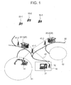
- FIG. 1 is an illustration showing the schematic construction of the mining field
- FIG. 2 is an illustration showing a traveling route for the dump truck at an earth dumping site.
- a traveling route 60 connecting a loading site 61 and an earth dumping site 62 there is provided a traveling route 60 connecting a loading site 61 and an earth dumping site 62.
- a power shovel 10 that performs loading operations for earth and sand or ore performs excavation operations.
- dump trucks 20-1, 20-2 are loaded at the loading site 61 with loads such as earth and sand or ore by the power shovel 10 and then, autonomously travel along the traveling route 60 toward the earth dumping site 62.
- the dump trucks 20-1, 20-2 discharge the loads.
- the dump truck is designated as the dump truck 20 unless the dump trucks 20-1 and 20-2 are discriminated from each other.
- the dump truck 20 autonomously travels on the traveling route 60 and switches the traveling direction from a forward movement to a reverse movement at a reversing point KBP to go back to a target point TP on the basis of map information and finally moves to and stops at a target stop position SP where a bund 400 is provided. Thereafter, the dump truck 20 performs an earth discharging operation and then travels toward the loading site 61 with itself unloaded.
- the traveling of the dump truck 20 from the target position TP to the target stop position SP is controlled based on sensor information from an external sensor 231 (refer to FIG. 3 and the like). The details of this control will be described later.
- the dump trucks 20-1, 20-2 are connected by telecommunication to a control server 31 installed in a control center 30 via a radio communication channel 40. Thus, the dump trucks 20-1, 20-2 travel under the control of the control server 31.
- the numeral 32 in FIG. 1 denotes a radio communication antenna connected to the control server 31, and numerals 41-1, 41-2 and 41-3 denote radio mobile stations.
- the dump truck 20 is provided with a position calculation device (not shown in FIG. 1 ) for receiving positioning radio waves from at least three navigation satellites 50-1, 50-2 and 50-3 of a global navigation satellite system (GNSS) to obtain the position of its own vehicle.
- GNSS global navigation satellite system
- GLONASS GLONASS
- GALILEO GLONASS
- the control server 31 is able to take into account travelling positions and target routes of all of the dump trucks 20-1, 20-2 and the operation goal and operation efficiency of the mine, calculate (determines) controlled demand vehicle speeds being the vehicle speeds (scalar quantities) that the control server 31 wants to apply to the respective dump trucks 20-1, 20-2 during the traveling thereof, and inform the respective dump trucks 20-1, 20-2 of the controlled demand vehicle speeds.
- FIG. 3A and FIG. 3B are block diagrams showing the hardware configurations of the control server 31 and the dump truck 20, respectively, wherein FIG. 3A represents the control server 31, whereas FIG. 3B represents the dump truck 20.
- the control server 31 includes a CPU 311, a RAM (Random Access Memory) 312, a ROM (Read-Only Memory) 313, an HDD (Hard Disk Drive) 314, an I/F (Interface) 315, and a bus 318, and is configured by having the CPU 311, the RAM 312, the ROM 313, the HDD 314 and the I/F 315 connected with one another through the bus 318.
- a CPU Central Processing
- RAM Random Access Memory
- ROM Read-Only Memory
- HDD Hard Disk Drive
- I/F Interface
- control server 31 is provided with an LCD (Liquid Crystal Display) 316 and an operating unit 317, which are connected to the I/F 315.
- LCD Liquid Crystal Display
- the CPU 311 is an arithmetic logical unit, which controls the whole operations of the control server 31.
- the RAM 312 is a volatile storage medium capable of performing high-speed reading and writing of information and is used as working areas when the CPU 311 processes information.
- the ROM 313 is a non-volatile storage medium for read-only use and stores therein an autonomous traveling control program featuring the present embodiment.
- the HDD 314 is a non-volatile storage medium capable of reading and writing information and stores therein an OS (Operating System), various control programs, application programs and the like.
- OS Operating System
- the LCD 316 is a visual user interface for enabling a user to confirm the traveling states of the dump trucks 20 in the mining field.
- the operating unit 317 is a user interface such as a keyboard or a touch panel (not shown) laminated on the LCD 316 for enabling the user to input information to the control server 31.
- a server-side communication unit 340 for connection to the radio communication channel 40 is connected to the I/F 315 of the control server 31.
- the dump truck 20 is provided with a traveling control device 200 for executing a control processing for autonomous traveling, a traveling drive device 210 for driving the traveling of the dump truck 20 in accordance with control instructions from the traveling control device 200, a position calculation device 220 for calculating estimated positions of its own vehicle of the dump truck 20, an external sensor 231 such as a laser sensor for recognizing surrounding circumstances of the dump truck 20, a body sensor 232 for recognizing vehicle information on a vehicle tilt, a load or the like, and a dump truck-side communication unit 240 for connection to the radio communication channel 40.
- a traveling control device 200 for executing a control processing for autonomous traveling
- a traveling drive device 210 for driving the traveling of the dump truck 20 in accordance with control instructions from the traveling control device 200
- a position calculation device 220 for calculating estimated positions of its own vehicle of the dump truck 20
- an external sensor 231 such as a laser sensor for recognizing surrounding circumstances of the dump truck 20
- a body sensor 232 for recognizing vehicle information on a vehicle tilt, a
- the traveling drive device 210 includes a brake system 211 for putting a brake on the dump truck 20, a steering motor 212 for altering the steering angle of the dump truck 20, and a traveling motor 213 for making the dump truck travel.
- the position calculation device 220 is a GPS device or an IMU for calculating estimated positions of its own vehicle upon receiving positioning radio waves from the navigation satellites 50-1, 50-2 and 50-3.
- the traveling control device 200 includes a CPU 201, a RAM 202, a ROM 203, an HDD 204, an I/F 205, and a bus 208, and is configured by having the CPU 201, the RAM 202, the ROM 203, the HDD 204 and the I/F 205 connected with one another through the bus 208. Further, the I/F 205 is connected to the traveling drive device 210, the position calculation device 220, the external sensor 231, the body sensor 232 and the dump truck-side communication unit 240.
- an autonomous traveling control program stored in a storage medium such as the ROMs 203, 313 or the HDDs 204, 314 or an optical disk (not shown) is read out into the RAMs 202, 312 and is executed under the control of the CPUs 201, 311.
- the autonomous traveling control program (software) and the hardware are brought into cooperation to constitute functional blocks that realize the functions of the control server 31 and the traveling control device 200.
- the configurations of the control server 31 and the traveling control device 200 are described as software-hardware combinations, the function of, in particular, the dump truck 20 may be configured by the use of logic circuits that realize the function of the autonomous traveling control program executed on the dump truck side.
- FIG. 4 is a functional block diagram showing primary functions of the control server 31.
- FIG. 5A and FIG. 5B are a chart and a table showing one example of route data stored in the control server 31, wherein FIG. 5A schematically shows the route data, whereas FIG. 5B shows a data structure example of the route data.
- the control server 31 is provided with a traveling permitted interval setting module 311a, a controlled demand vehicle speed determination module 311b, a server-side communication control module 311c, a route data storage module 314a, and an operating control information data base (hereinafter, the data base is abbreviated as "DB") 314b.
- the traveling permitted interval setting module 311a, the controlled demand vehicle speed determination module 311b and the server-side communication control module 311c are configured by the autonomous traveling control program executed by the control server 31.
- the route data storage module 314a is configured by the use of a storage device of a fixed storage type such as the HDD 314. As shown in FIG. 5A , the route data is defined by position information on respective points (hereafter called “nodes”) 22 on the traveling route 60 and links 21 connecting the respective nodes 22. Further, the route data may include topographic information of the mine and absolute coordinates (three-dimensional actual coordinates calculated based on the positioning radio waves) of the respective nodes 22. Each node 22 is given identification information (hereafter called "node ID”) for uniquely identifying the node 22.
- node ID identification information
- Each link 21 has a forward direction (the arrow A direction in FIG. 5A ) and also has a head node and an end node defined. Then, as shown in FIG. 5B , in the route data, a link ID (e.g., 21A) being identification data for uniquely identifying each link is correlated with data that includes coordinate values (X 22A , Y 22A ) of a head node ID and coordinate values (X 22B , Y 22B ) of an end node ID for the link and a route demand vehicle speed V 21A , a road width W 21A , a gradient S 21A , and a curvature C 21A at the time of traveling on the link.
- a link ID e.g., 21A
- a link ID being identification data for uniquely identifying each link is correlated with data that includes coordinate values (X 22A , Y 22A ) of a head node ID and coordinate values (X 22B , Y 22B ) of an end node ID for the
- the route demand vehicle speed is determined in dependence on a road specification such as the gradient, curvature and road width of the route.
- the route demand vehicle speed becomes a possible target vehicle speed at the time of actual traveling of the dump truck 20.
- the operating control information DB 314b stores operation control information indicating the positions of the respective dump trucks 20 traveling on the traveling route 60.
- the traveling permitted interval setting module 311a responds to traveling permission demand information transmitted from each dump truck 20 and sets the next traveling permitted interval to the dump truck 20. Specifically, with reference to the operation control information in the operating control information DB 314b, the traveling permitted interval setting module 311a grasps the position of the other dump truck traveling ahead of the dump truck 20 concerned. Then, with reference to the route data in the route data storage module 314a, the traveling permitted interval setting module 311a sets a forward boundary point of a newly set traveling permitted interval at a point that is behind by a distance (stop enabling distance) which is necessary at least for the dump truck 20 to be braked and stopped, from the present position of the other dump truck traveling ahead thereof on the traveling route 60.
- a distance stop enabling distance
- the traveling permitted interval setting module 311a sets a rearward boundary point at a position that is spaced by the stop enabling distance from the present position of the dump truck 20 concerned. Then, the traveling permitted interval setting module 311a sets the interval between the forward boundary point and the rearward boundary point as a new traveling permitted interval that is given to the dump truck 20 issuing the traveling permission demand.
- the controlled demand vehicle speed determination module 311b determines a controlled demand vehicle speed. Specifically, the controlled demand vehicle speed determination module 311b reads out route data from the route data storage module 314a and, with reference to the operating information stored in the operating control information DB 314b, determines a controlled demand vehicle speed taking into account a route demand vehicle speed set in correspondence to a link that is included in the new traveling permitted interval having been set for the dump truck 20, a distance of the dump truck 20 from the vehicle ahead, and the state of traffic congestion.
- the maximum controlled demand vehicle speed is the vehicle speed that is made to correspond to each link in the route data, and in the case of traffic congestion, a vehicle speed that is slower than the maximum controlled demand vehicle speed is determined as the controlled demand vehicle speed.
- the controlled demand vehicle speed is outputted to the traveling permitted interval setting module 311a.
- the traveling permitted interval setting module 311a generates traveling permission response information that indicates the forward boundary point and the rearward boundary point of the set new traveling permitted interval and the controlled demand vehicle speed, and outputs the generated information to the server-side communication control module 311c.
- the server-side communication control module 311c controls receiving the traveling permission demand information for each dump truck 20 and transmitting the traveling permission response information generated in response to the traveling permission demand information.
- FIG. 6 is a side view showing the entire construction of the dump truck 20
- FIG. 7 is a block diagram showing the functional configuration of the dump truck 20.
- the dump truck 20 is provided with front wheels 810 and rear wheels 820 attached to front and rear parts of a body frame 840, a vessel 830 rotatably supported on the body frame 840 through a support shaft 860, a hoist cylinder 850 for pivotally moving the vessel 830 about the support shaft 860 when telescopically operated, the external sensor 231 for detecting the bund 400 (refer to FIG. 9 ) when the dump truck 20 moves, and the traveling control device 200 for controlling the traveling of the dump truck 20.
- the body frame 840 has primary components such as a drive system and a driver's seat mounted thereon, and the vehicle is configured to be able to travel freely on the traveling surface by the provision of the front wheels 810 and the rear wheels 820.
- the hoist cylinder 850 When the hoist cylinder 850 is telescopically extended, the vessel 830 is operated to elevate a front end and increase the slant angle as the pivot movement is effected about the support shaft 860 and thus, is able to discharge the load (transport object) 870 loaded on the vessel 830 from an rear end of the same (refer to FIG. 10 ).
- a potentiometer (rotary potentiometer) 865 for measuring the rotational angle of the support shaft 860 is set on the support shaft 860 as angle detection means for detecting the slant angle of the vessel 830 relative to the body frame 840.
- the numeral 875 denotes a rear wheel axle of the rear wheels 820. It is to be noted that the traveling drive device 210, the position calculation device 220, the body sensor 232 and the dump truck-side communication unit 240 that are shown in FIG. 3B are omitted in FIG. 6 .
- the traveling control device 200 is provided with a route data storage module 204a storing the traveling route and its attendant information, a route data extraction module 201c for extracting appropriate data from the route data storage module 204a, a stop position determining module (stop position determining device) 510 for calculating a stop position for the dump truck 20, and a body information computation module 201e for recognizing the body state such as a traveling speed, a steering angle and a live load.
- the traveling control device 200 is further provided with an action command module 201f for determining a target vehicle speed, a target route and the like for its own vehicle to output command information that is necessary for its own vehicle to follow the target route, a target route follow-up module 201g for determining control variables for driving, braking and steering that are necessary for its own vehicle to move along a target route at a target vehicle speed, a traveling permission demand module 201h for demanding the setting of a new traveling permitted interval for the next traveling when its own vehicle comes close to an end point (forward boundary point) of the traveling permitted interval during the ongoing traveling, and a dump truck-side communication control module 201i for executing radio communication control with the control server 31.
- an action command module 201f for determining a target vehicle speed, a target route and the like for its own vehicle to output command information that is necessary for its own vehicle to follow the target route
- a target route follow-up module 201g for determining control variables for driving, braking and steering that are necessary for its own vehicle to move along a target
- the route data storage module 204a records route data expressing a route along which the dump truck 20 is to travel, as aggregate of links each having points called nodes at opposite ends. Further, each link ID and its attendant information attendant thereupon are configured to be associated so that the designation of a link makes it possible to extract data tied to the link.
- the route data extraction module 201c uses the position information calculated by the position calculation device 220 as a base for extracting route data that expresses the neighborhood of the calculated position.
- the route data extraction module 201c outputs the extracted route data to the action command module 201f.
- the stop position determining module 510 discriminates the presence/absence and the shape of an obstacle that exists particularly ahead in the traveling direction of the dump truck 20 (for example, the vehicle ahead, the bund 400 or the like) based on an output from the external sensor 231 such as a laser sensor, and where the obstacle is the bund 400, calculates a target stop position for stopping the dump truck 20 in the neighborhood of the bund 400. Then, the stop position determining module 510 outputs a calculation result to the action command module 201f.
- the external sensor 231 besides the laser sensor, there may be used a millimeter-wave sensor, a stereo camera or the like.
- the body information computation module 201e computes values representing the body state of the dump truck 20 such as a steering angle, a traveling speed and a live load based on the outputs from various body sensors 232. For example, the body information computation module 201e computes a steering angle based on the output from a rotary angle sensor attached to a steering shaft. Further, the body information computation module 201e computes a traveling speed based on rotational speeds outputted from wheel speed sensors measuring the rotational speeds of the front wheels 810 and the rear wheels 820 as well as on the tire specification.
- the body information computation module 201e computes a live load based on the outputs from pressure sensors capable of measuring the pressures in suspensions installed for the respective wheels.
- the action command module 201f responds to the detection result to perform a traveling control corresponding to the body information, for example, to advance the braking timing earlier in the case of empty load than in the case of being loaded.
- the target route follow-up module 201g is for executing a control that makes the dump truck 20 travel along the target route at the target vehicle speed determined by the action command module 201f and includes a target torque generation module 501 for generating a traveling motor torque command needed to realize a target vehicle speed and a target steering angle generation module 502 for generating a steering angle command to realize a target route.
- the target torque generation module 501 obtains a target vehicle speed from the action command module 201f, feeds back the difference between the target vehicle speed and the present vehicle speed, and generates a target traveling torque to decrease the difference.
- the target steering angle generation module 502 obtains traveling permission response information and position information on a target route (traveling permitted interval) from the dump truck-side communication control module 201i and generates a target steering angle so that the dump truck 20 does not deviate from the target route.
- the target route follow-up module 201g also has a function of controlling the traveling drive device 210 in accordance with a command from the action command module 201f when the dump truck 20 is to move to the target stop position SP close to the bund 400 for earth discharging.
- the traveling permission demand module 201h compares the position data of its own vehicle obtained from the position calculation device 220 with the route data read out from the route data storage module 204a, judges whether or not its own vehicle has arrived at the point (traveling permission demand point) where the traveling permission demand information is to be transmitted for demanding the setting of the next traveling permitted interval, and in the case of having arrived, transmits the traveling permission demand information to the dump truck-side communication control module 201i.
- the dump truck-side communication control module 201i performs the control of transmitting to the control server 31 the traveling permission demand information for demanding the next traveling permitted interval and of receiving the traveling permission response information (including controlled demand vehicle speed information) from the control server 31.
- FIG. 8 is a block diagram showing the details of the stop position determining module 510.
- the stop position determining module 510 is provided with an obstacle identification module (bund identification module) 520 for identifying an obstacle (the vehicle ahead, the bund 400 or the like) on the traveling surface based on the information from the external sensor 231 and a target stop position calculation module 530 for calculating a target stop position SP for the dump truck 20.
- an obstacle identification module (bund identification module) 520 for identifying an obstacle (the vehicle ahead, the bund 400 or the like) on the traveling surface based on the information from the external sensor 231
- a target stop position calculation module 530 for calculating a target stop position SP for the dump truck 20.
- the obstacle identification module 520 includes a traveling surface detection module 521 for detecting the traveling surface for the dump truck 20, a bund angle changing position detection module 522 for detecting a position at which a wall surface 400a of the bund 440 changes in angle, a bund angle detection module (bund angle calculation module) 523 for detecting the angle of the wall surface 400a of the bund 400, and a bund trailing edge position detection module 524 for detecting a trailing edge position of the bund 400.
- a traveling surface detection module 521 for detecting the traveling surface for the dump truck 20
- a bund angle changing position detection module 522 for detecting a position at which a wall surface 400a of the bund 440 changes in angle
- a bund angle detection module (bund angle calculation module) 523 for detecting the angle of the wall surface 400a of the bund 400
- a bund trailing edge position detection module 524 for detecting a trailing edge position of the bund 400.
- FIG. 9 is an illustration showing the state that the external sensor 231 detects the bund 400.
- the external sensor 231 is constituted by, for example, a laser sensor and is configured to be able to measure distances to a plurality of points within a measuring range of the external sensor 231. More specifically, FIG. 9 shows the state that the external sensor 231 is two dimensional in measuring range and takes as the measuring range an area covering the front to rear sides at the lower side of the dump truck 20.
- the traveling surface detection module 521 determines a traveling surface 601 based on a sequence of measured points on a surface on which the dump truck 20 travels. More specifically, the traveling surface detection module 521 calculates the traveling surface 601 by using a sequence of measured points at a predetermined area, for example, between the front wheels 810 and the rear wheels 820 to compute an approximate straight line from the sequence of measure points.
- the bund angle changing position detection module 522 calculates a first bund angle changing position 401 at which the sequence of measured points change from the traveling surface 601. Where a plurality of changing points are detected, the bund angle changing position detection module 522 calculates the bund angle changing positions up to the n-th.
- the bund angle detection module 523 calculates an angle ⁇ (refer to FIG. 11 ; hereafter, this angle will be called “leading edge angle") that the straight line of the traveling surface 601 makes with a line 602 (wall surface 400a) following the angle change at the angle change position detected by the bund angle changing position detection module 522.
- the bund trailing edge position detection module 524 detects a bund peak from the fluctuation in the sequence of measured points and then, further detects a position at which the sequence of measured points turns downward in the vertical direction, to detect the position as a bund trailing edge position 402. Further, where the measured points do not change vertically downward, the bund trailing edge position detection module 524 detects as the bund trailing edge position 402 a position defined by the rearmost one of the measured points on the bund peak.
- the target stop position calculation module 530 determines a target stop position SP for the dump truck 20 based on output values from the traveling surface detection module 521, the bund angle changing position detection module 522, the bund angle detection module 523 and the bund trailing edge position detection module 524.
- the target stop position SP is defined as the distance from the external sensor 231 in the horizontal direction. That is to say, configuration is so taken that when the distance from the external sensor 231 to the bund 400 in the horizontal direction becomes SP, the dump truck 20 is stopped with the stop position taking an appropriate position for earth discharging (refer to FIG. 11 and the like).
- FIG. 10 shows the state that the dump truck 20 performs earth discharging. Where discharging the load 870 toward the bottom of a scarp, the dump truck 20 goes backward and comes close to the bund 400 to stop there. In this state, the dump truck 20 tilts the vessel 830 by the control of the hoist cylinder 850 to discharge the load 870 loaded on the vessel 830 rearward.
- the symbol Ds represents a distance between the external sensor 231 and the center of the rear wheel axle 875 in the horizontal direction
- the symbol Do represents a distance between the center of the rear wheel axle 875 and the bund trailing edge position 402 in the horizontal direction.
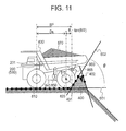
- FIG. 11 shows the state that the dump truck 20 is in contact with the bund 400.
- the leading edge angle ⁇ of the bund 400 is sufficiently large, the dump truck 20 is unable to go over the bund 400. Therefore, as shown in FIG. 11 , it is desirable that the dump truck 20 stop at a position where the rear wheels 820 are in contact with the bund 400.
- it is possible to calculate the target stop position SP by performing geometric computations based on the angle ⁇ detected by the bund angle detection module 523 and the radius R of the rear wheel tires.
- the target stop position calculation module 530 determines as the target stop position SP a position at which the external sensor 231 is spaced from the first bund angle changing position 401 by a distance obtained by the calculation of Ds+R*tan( ⁇ /2). The calculation may be made by the use of the diameter D of the rear wheel tires instead of the radius R.
- FIG. 12 shows another example where the dump truck 20 stops at the earth discharging position.
- the bund 400 has angle changes of two or more steps. Specifically, a first bund angle changing position 401 is so slight in angle change as to be gone over by the dump truck 20, while a second bund angle changing position 403 is so large as not to be gone over by the dump truck 20.
- the traveling control device 200 judges that the dump truck 20 is able to go over the first bund angle changing position 401, from a first bund angle ( ⁇ 1) detected by the bund angle detection module 523 and continues the reverse travel. At this time, it is possible to detect a pitch angle ⁇ p by the use of the body sensor 232 for posture detection such as an IMU (Inertial Measurement Unit) provided on the dump truck 20.
- IMU Inertial Measurement Unit
- the target stop position calculation module 530 calculates as the target stop position SP such a position that the center of the rear wheel axle 875 comes to a position where the vessel 830 reaches a position being beyond the bund trailing edge position 402 and determined by the expression Ds*cos( ⁇ p)+Do*cos( ⁇ p) compensating the aforementioned distances Do and Ds. Where a bund 400 of the angle which cannot been gone over is detected, the position at which the rear wheels 820 are in contact with the bund 400 is set as the target stop position SP similarly to the case described before.
- FIG. 13 is a flow chart showing the processing steps of the stop position determining module 510.
- the traveling surface detection module 521 computes the traveling surface 601 based on the sequence of measured points detected by the external sensor 231.
- the bund angle changing position detection module 522 computes the first bund angle changing position 401 based on the sequence of measured points detected by the external sensor 231. Further, the bund angle detection module 523 computes the leading edge angle ⁇ of the bund 400 based on the sequence of measured points detected by the external sensor 231. At this time, where the bund angle changing positions and the leading edge angles are paired plurally, computations are performed for all of the pairs.
- the bund trailing edge position detection module 524 calculates the bund trailing edge position 402 based on the sequence of measured points detected by the external sensor 231.
- the target stop position calculation module 530 judges whether or not the leading edge angle (bund angle) ⁇ at the n-th bund angle changing position is equal to or larger than a threshold value.
- the threshold value herein is set at an angle of the degree that the dump truck 20 is unable to go over the bund 400. If the leading edge angle ⁇ is equal to or larger than the threshold value, the bund angle concerned is judged to be unable to be gone over, and the step S605 is then reached. If the leading edge angle ⁇ is smaller than the threshold value, return is made to the step S604. At this time, the first bund angle changing position 401 and the bund leading edge angle ⁇ that are taken as objectives for computation are altered to those for the next (n+1th).
- the target stop position calculation module 530 determines the target stop position Sp to such a position that the external sensor 231 is away from the first bund angle changing position 401 by a distance calculated by the expression Ds+R*tan( ⁇ /2) (refer to FIG. 11 ).
- the target stop position SP is geometrically calculated from the slant angle of the wall surface 400a of the bund 400, and the dump truck 20 is stopped at the target stop position SP, whereby the rear wheels 820 are brought into such a close state as to be in contact or not with the wall surface 400a of the bund 400. Therefore, it is possible to stop the dump truck 20 at a position desired for the earth discharging operation.
- the stop position can be calculated taking the shape of the bund 400 into consideration, it is possible to control the dump truck 20 to stop at an appropriate position even where the shape of the bund 400 is changed.
- a dump truck 1020 on which a stop position determining module 1510 is mounted according to a second embodiment.
- the second embodiment is the same as the first embodiment except for the difference in the computation method that is executed by a target stop position calculation module 1530 for the target stop position SP, and hence, description will be focused on the difference.
- FIG. 14 shows the state that the dump truck 1020 is approaching the bund 400 for earth discharging.
- the symbol R represents the radius of the rear wheels 820
- the symbol Ds represent a horizontal distance from the external sensor 231 to the center of the rear wheel axle 875.
- the symbol L1 is defined as a measured distance to the first bund angle changing position 401 detected by the external sensor 231.
- the bund 400 where formed through the stacking of earth and sand or the like as shown in the figure, is approximately determined by an angle called repose angle that enables the shape to be kept stably without the collapse of the earth and sand, the reading edge of a slope face of the bund 400 often becomes relatively gentle in angle even though depending on the property of earth and sand material and generally, often becomes smaller than 40 degrees.
- the rear wheels 820 support the dead load with the tire rubber yielding and thus, have a ground-contact length represented as Lc.
- Lc ground-contact length
- the target stop position calculation module 1530 of the stop position determining module 1510 in the second embodiment determines as the target stop position SP a position at which the external sensor 231 is apart from the first bund angle changing position 401 by the distance L1.
- the symbol Lc is a value that is determined by the kind and air pressure of the tires and the axle weight, but may be determined by a function of the gross weight for each model of the dump truck 20 or simply by a constant depending on each model.
- a bund 400 is constructed by concrete or the like and is provided to be perpendicular to the ground. That is, as shown in FIG. 17 , the part of the rear wheels 820 to be first brought into contact with the bund 400 is the part of the rear wheels 820 projecting most rearward, namely, the part at the height of the rear wheel axle 875, and the projecting amount from the rear wheel axle 875 is the symbol R representing the radius of the rear wheels 820. That is, where the symbol L2 represents the distance measured from the external sensor 231 to a bund position 403 at the height of the rear wheel axle 875, it is desirable to set as the target stop position SP a position that makes the symbol L2 in FIG. 16 equal to the sum Ds+R.
- the distance to attain a stop target changes in dependence on the shape of the bund 400, and thus, in order to judge which of the example shown in FIG. 14 and the example shown in FIG. 16 is the case, it is suitable to judge whether or not the rear end of the rear wheels 820 can project beyond the first bund angle changing position 401. Therefore, important is the position 403 of the bund 400 at the height of the rear wheel axle 875 which corresponds to the part of the rear wheels 820 projecting most rearward, and such judgment can be done by comparing the measured distance L2 from the external sensor 231 to the bund position 403 at the height of the rear wheel axle 875 in FIG. 14 or FIG. 16 with the measured distance L1 from the external sensor 231 to the first bund angle changing position 401.
- the distance to either one that is earlier brought into contact with the bund 400 is set as a stop target. That is, the object can be attained by judging whether the distance L1 detected by the external sensor 231 reaches the sum Ds+Lc/2 or the distance L2 reaches the sum Ds+R and by effecting the stop when either one of them is attained earlier.
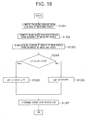
- FIG. 18 shows a calculation procedure for the target stop position SP which includes parts for the judgment shown here.
- the traveling surface detection module 521 computes the traveling surface 601 from the sequence of measured points detected by the external sensor 231.
- the bund angle changing position detection module 522 computes the first bund angle changing position 401 based on the sequence of measured points detected by the external sensor 231.
- the target stop position calculation module 1530 calculates the distance L1 from the first bund angle changing position 401.
- the bund angle detection module 523 computes the leading edge angle ⁇ of the bund 400 based on the sequence of measured points detected by the external sensor 231.
- the target stop position calculation module 1530 calculates the distance L2 from the external sensor 231 to the position 403 at the height of the radius R of the tires based on the leading edge angle ⁇ and the tire radius R.
- the target stop position calculation module 1530 executes the step S1305 if the relation L1-Lc/2 ⁇ L2-R is true, but executes the step S1306 if the relation is false.
- the target stop position calculation module 1530 determines the target stop position SP based on the reverse distance LB.
- the second embodiment in the same manner as the first embodiment, it is possible to identify the shape of the bund 400 and to stop the dump truck 1020 at an appropriate position depending on the shape of the bund 400. Accordingly, it is possible to stop the dump truck 1020 at a desired position for the earth discharging operation. Moreover, even where the shape of the bund 400 is changed, it is likewise possible to move the dump truck 1020 to an appropriate earth discharging position.
- the present invention is applicable to other transport vehicles than the dump trucks, for example, to wheel loaders and the like.
Landscapes
- Engineering & Computer Science (AREA)
- Mechanical Engineering (AREA)
- Transportation (AREA)
- Automation & Control Theory (AREA)
- Physics & Mathematics (AREA)
- Civil Engineering (AREA)
- Structural Engineering (AREA)
- General Engineering & Computer Science (AREA)
- Mining & Mineral Resources (AREA)
- General Physics & Mathematics (AREA)
- Mathematical Physics (AREA)
- Aviation & Aerospace Engineering (AREA)
- Radar, Positioning & Navigation (AREA)
- Remote Sensing (AREA)
- Architecture (AREA)
- Control Of Position, Course, Altitude, Or Attitude Of Moving Bodies (AREA)
- Traffic Control Systems (AREA)
Abstract
Description
- The present invention relates to a stop position determining device for a transport vehicle and further, to a transport vehicle with the device.
- In open pit mines or the like, a transport vehicle such as a dump truck travels for transporting evacuated ore or earth and sand. The transport vehicle loads the transport object on its vessel(body) at a loading site and transports the loaded transport object to an earth dumping site to perform earth discharging. A bund for restraining the transport vehicle from traveling outside a traveling area is disposed at the earth dumping site. At this time, there arises a case where the transport object on the vessel is discharged outside the bund after the transport vehicle is stopped near the bund.
- A technology for stopping a vehicle near a bund is known from Japanese Patent Application Publication No.
2007-90939 - In discharging the transport object at an earth dumping site of a mine or the like, it is desirable that a transport vehicle be stopped as close to a bund as possible. However, the shapes of bunds vary from mine to mine, and hence, there arises a case where the stop position of the transport vehicle has to be altered in dependence on the shape of the bund. Further, in mines or the like, there arises a case where the shape of a bund is changed in dependence on the operations of the transport vehicle. Therefore, there arises a case where the stop position of the transport vehicle has to be altered with the change in shape of the bund. However, in the aforementioned Japanese application, nothing is taken into consideration about stopping the vehicle close to the bund in dependence on the shape of the bund.
- The present invention has been made taking the aforementioned circumstances into consideration, and it is an object of the present invention to make a transport vehicle stop close to a bund in dependence on the shape of the bund.
- In order to accomplish the aforementioned object, a stop position determining device for a transport vehicle according to the present invention comprises a bund identification module that identifies the shape of a bund provided on a traveling surface based on information from an external sensor provided on the transport vehicle and a target stop position calculation module that calculates a target stop position for the transport vehicle based on the shape of the bund identified by the bund identification module.
- According to the present invention, it is possible to stop the transport vehicle close to the bund in dependence on the shape of the bund. The foregoing and other objects, constructions and many of the attendant advantages of the present invention may readily be appreciated from the description of the following preferred embodiments.
- Non-limiting and non-exhaustive embodiments of the present embodiments are described with reference to the following FIGURES, wherein like reference signs refer to like parts throughout the various views unless otherwise specified.
-
FIG. 1 is an illustration showing a schematic construction in a mining filed. -
FIG. 2 is an illustration showing a traveling route for a dump truck in an earth dumping site shown inFIG. 1 . -
FIG. 3A and FIG. 3B are block diagrams showing hardware configurations of a control server and a dump truck, whereinFIG. 3A shows the control server, whileFIG. 3B shows the dump truck. -
FIG. 4 is a functional block diagram showing primary functions of the control server. -
FIG. 5A and FIG. 5B are a chart and a table showing one example of route data stored in the control server, whereinFIG. 5A schematically shows the route data, whileFIG. 5B shows a data structure example of the route data. -
FIG. 6 is a side view showing the entire construction of the dump truck. -
FIG. 7 is a block diagram showing the internal configuration of the dump truck. -
FIG. 8 is a block diagram showing a stop position determining module shown inFIG. 7 . -
FIG. 9 is an illustration showing the state that an external sensor detects a bund. -
FIG. 10 is an illustration showing the state that the dump truck performs earth discharging. -
FIG. 11 is an illustration showing the state that the dump truck is in contact with the bund. -
FIG. 12 is an illustration showing another example in which the dump truck stops at an earth discharging position. -
FIG. 13 is a flow chart showing processing steps taken by a stop position determining module in a first embodiment. -
FIG. 14 is an illustration showing one example wherein the bund is formed by having earth and sand or the like piled up. -
FIG. 15 is an illustration showing the relation between rear wheels and the stop position in the case of the bund shown inFIG. 14 . -
FIG. 16 is an illustration showing one example where the bund is a structure made by concrete or the like. -
FIG. 17 is an illustration showing the relation between the rear wheels and the stop position in the case of the bund shown inFIG. 16 . -
FIG. 18 is a flow chart showing processing steps taken by a stop position determining module in a second embodiment. - Hereafter, embodiments of the present invention will be described with reference to the drawings. The following description is directed to concrete examples of the content of the present invention, and the present invention is not limited to the following description and may be subjected, within the scope of the technical concept disclosed in the present specification, to various alterations and modifications made by a person skilled in the art. In all drawings for describing the present invention, the same reference signs are indicative in the case of same function, and repeat description is omitted.
- With reference to
FIG. 1 andFIG. 2 , description will be made regarding the schematic construction of a mining field in which a mining dump truck travels as a transport vehicle on which a stop position determining module is mounted according to the present embodiment.FIG. 1 is an illustration showing the schematic construction of the mining field, andFIG. 2 is an illustration showing a traveling route for the dump truck at an earth dumping site. - As shown in
FIG. 1 , in the mining field, there is provided atraveling route 60 connecting aloading site 61 and anearth dumping site 62. At theloading site 61, apower shovel 10 that performs loading operations for earth and sand or ore performs excavation operations. Then, dump trucks 20-1, 20-2 are loaded at theloading site 61 with loads such as earth and sand or ore by thepower shovel 10 and then, autonomously travel along thetraveling route 60 toward theearth dumping site 62. Upon arriving at theearth dumping site 62, the dump trucks 20-1, 20-2 discharge the loads. In the following description, the dump truck is designated as thedump truck 20 unless the dump trucks 20-1 and 20-2 are discriminated from each other. - At the
earth dumping site 62, as shown inFIG. 2 , thedump truck 20 autonomously travels on thetraveling route 60 and switches the traveling direction from a forward movement to a reverse movement at a reversing point KBP to go back to a target point TP on the basis of map information and finally moves to and stops at a target stop position SP where abund 400 is provided. Thereafter, thedump truck 20 performs an earth discharging operation and then travels toward theloading site 61 with itself unloaded. The traveling of thedump truck 20 from the target position TP to the target stop position SP is controlled based on sensor information from an external sensor 231 (refer toFIG. 3 and the like). The details of this control will be described later. - The dump trucks 20-1, 20-2 are connected by telecommunication to a
control server 31 installed in acontrol center 30 via aradio communication channel 40. Thus, the dump trucks 20-1, 20-2 travel under the control of thecontrol server 31. The numeral 32 inFIG. 1 denotes a radio communication antenna connected to thecontrol server 31, and numerals 41-1, 41-2 and 41-3 denote radio mobile stations. - The
dump truck 20 is provided with a position calculation device (not shown inFIG. 1 ) for receiving positioning radio waves from at least three navigation satellites 50-1, 50-2 and 50-3 of a global navigation satellite system (GNSS) to obtain the position of its own vehicle. As the GNSS, besides GPS, there may be used GLONASS or GALILEO. - The
control server 31 is able to take into account travelling positions and target routes of all of the dump trucks 20-1, 20-2 and the operation goal and operation efficiency of the mine, calculate (determines) controlled demand vehicle speeds being the vehicle speeds (scalar quantities) that thecontrol server 31 wants to apply to the respective dump trucks 20-1, 20-2 during the traveling thereof, and inform the respective dump trucks 20-1, 20-2 of the controlled demand vehicle speeds. - Next, electric configurations of the
control server 31 and thedump truck 20 shown inFIG. 1 will be described with reference toFIG. 3A and FIG. 3B. FIG. 3A and FIG. 3B are block diagrams showing the hardware configurations of thecontrol server 31 and thedump truck 20, respectively, whereinFIG. 3A represents thecontrol server 31, whereasFIG. 3B represents thedump truck 20. - As shown in
FIG. 3A , thecontrol server 31 includes aCPU 311, a RAM (Random Access Memory) 312, a ROM (Read-Only Memory) 313, an HDD (Hard Disk Drive) 314, an I/F (Interface) 315, and abus 318, and is configured by having theCPU 311, theRAM 312, theROM 313, theHDD 314 and the I/F 315 connected with one another through thebus 318. - Further, the
control server 31 is provided with an LCD (Liquid Crystal Display) 316 and anoperating unit 317, which are connected to the I/F 315. - The
CPU 311 is an arithmetic logical unit, which controls the whole operations of thecontrol server 31. - The
RAM 312 is a volatile storage medium capable of performing high-speed reading and writing of information and is used as working areas when theCPU 311 processes information. - The
ROM 313 is a non-volatile storage medium for read-only use and stores therein an autonomous traveling control program featuring the present embodiment. - The
HDD 314 is a non-volatile storage medium capable of reading and writing information and stores therein an OS (Operating System), various control programs, application programs and the like. - The
LCD 316 is a visual user interface for enabling a user to confirm the traveling states of thedump trucks 20 in the mining field. - The
operating unit 317 is a user interface such as a keyboard or a touch panel (not shown) laminated on theLCD 316 for enabling the user to input information to thecontrol server 31. - A server-
side communication unit 340 for connection to theradio communication channel 40 is connected to the I/F 315 of thecontrol server 31. - On the other hand, as shown in
FIG. 3B , thedump truck 20 is provided with a travelingcontrol device 200 for executing a control processing for autonomous traveling, a travelingdrive device 210 for driving the traveling of thedump truck 20 in accordance with control instructions from the travelingcontrol device 200, aposition calculation device 220 for calculating estimated positions of its own vehicle of thedump truck 20, anexternal sensor 231 such as a laser sensor for recognizing surrounding circumstances of thedump truck 20, abody sensor 232 for recognizing vehicle information on a vehicle tilt, a load or the like, and a dump truck-side communication unit 240 for connection to theradio communication channel 40. - The traveling
drive device 210 includes abrake system 211 for putting a brake on thedump truck 20, asteering motor 212 for altering the steering angle of thedump truck 20, and a travelingmotor 213 for making the dump truck travel. - The
position calculation device 220 is a GPS device or an IMU for calculating estimated positions of its own vehicle upon receiving positioning radio waves from the navigation satellites 50-1, 50-2 and 50-3. - The traveling
control device 200 includes aCPU 201, aRAM 202, aROM 203, anHDD 204, an I/F 205, and abus 208, and is configured by having theCPU 201, theRAM 202, theROM 203, theHDD 204 and the I/F 205 connected with one another through thebus 208. Further, the I/F 205 is connected to the travelingdrive device 210, theposition calculation device 220, theexternal sensor 231, thebody sensor 232 and the dump truck-side communication unit 240. - In the hardware configuration like this, an autonomous traveling control program stored in a storage medium such as the
ROMs HDDs RAMs CPUs control server 31 and the travelingcontrol device 200. Although in the present embodiment, the configurations of thecontrol server 31 and the travelingcontrol device 200 are described as software-hardware combinations, the function of, in particular, thedump truck 20 may be configured by the use of logic circuits that realize the function of the autonomous traveling control program executed on the dump truck side. - Next, the functional configuration of the
control server 31 will be described with reference toFIG. 4 ,FIG. 5A and FIG. 5B .FIG. 4 is a functional block diagram showing primary functions of thecontrol server 31.FIG. 5A and FIG. 5B are a chart and a table showing one example of route data stored in thecontrol server 31, whereinFIG. 5A schematically shows the route data, whereasFIG. 5B shows a data structure example of the route data. - As shown in
FIG. 4 , thecontrol server 31 is provided with a traveling permittedinterval setting module 311a, a controlled demand vehiclespeed determination module 311b, a server-sidecommunication control module 311c, a routedata storage module 314a, and an operating control information data base (hereinafter, the data base is abbreviated as "DB") 314b. The traveling permittedinterval setting module 311a, the controlled demand vehiclespeed determination module 311b and the server-sidecommunication control module 311c are configured by the autonomous traveling control program executed by thecontrol server 31. - The route
data storage module 314a is configured by the use of a storage device of a fixed storage type such as theHDD 314. As shown inFIG. 5A , the route data is defined by position information on respective points (hereafter called "nodes") 22 on the travelingroute 60 andlinks 21 connecting therespective nodes 22. Further, the route data may include topographic information of the mine and absolute coordinates (three-dimensional actual coordinates calculated based on the positioning radio waves) of therespective nodes 22. Eachnode 22 is given identification information (hereafter called "node ID") for uniquely identifying thenode 22. - Each
link 21 has a forward direction (the arrow A direction inFIG. 5A ) and also has a head node and an end node defined. Then, as shown inFIG. 5B , in the route data, a link ID (e.g., 21A) being identification data for uniquely identifying each link is correlated with data that includes coordinate values (X22A, Y22A) of a head node ID and coordinate values (X22B, Y22B) of an end node ID for the link and a route demand vehicle speed V21A, a road width W21A, a gradient S21A, and a curvature C21A at the time of traveling on the link. - The route demand vehicle speed is determined in dependence on a road specification such as the gradient, curvature and road width of the route. The route demand vehicle speed becomes a possible target vehicle speed at the time of actual traveling of the
dump truck 20. - The operating
control information DB 314b stores operation control information indicating the positions of therespective dump trucks 20 traveling on the travelingroute 60. - The traveling permitted
interval setting module 311a responds to traveling permission demand information transmitted from eachdump truck 20 and sets the next traveling permitted interval to thedump truck 20. Specifically, with reference to the operation control information in the operatingcontrol information DB 314b, the traveling permittedinterval setting module 311a grasps the position of the other dump truck traveling ahead of thedump truck 20 concerned. Then, with reference to the route data in the routedata storage module 314a, the traveling permittedinterval setting module 311a sets a forward boundary point of a newly set traveling permitted interval at a point that is behind by a distance (stop enabling distance) which is necessary at least for thedump truck 20 to be braked and stopped, from the present position of the other dump truck traveling ahead thereof on the travelingroute 60. Further, the traveling permittedinterval setting module 311a sets a rearward boundary point at a position that is spaced by the stop enabling distance from the present position of thedump truck 20 concerned. Then, the traveling permittedinterval setting module 311a sets the interval between the forward boundary point and the rearward boundary point as a new traveling permitted interval that is given to thedump truck 20 issuing the traveling permission demand. - The controlled demand vehicle
speed determination module 311b determines a controlled demand vehicle speed. Specifically, the controlled demand vehiclespeed determination module 311b reads out route data from the routedata storage module 314a and, with reference to the operating information stored in the operatingcontrol information DB 314b, determines a controlled demand vehicle speed taking into account a route demand vehicle speed set in correspondence to a link that is included in the new traveling permitted interval having been set for thedump truck 20, a distance of thedump truck 20 from the vehicle ahead, and the state of traffic congestion. Usually, the maximum controlled demand vehicle speed is the vehicle speed that is made to correspond to each link in the route data, and in the case of traffic congestion, a vehicle speed that is slower than the maximum controlled demand vehicle speed is determined as the controlled demand vehicle speed. The controlled demand vehicle speed is outputted to the traveling permittedinterval setting module 311a. - The traveling permitted
interval setting module 311a generates traveling permission response information that indicates the forward boundary point and the rearward boundary point of the set new traveling permitted interval and the controlled demand vehicle speed, and outputs the generated information to the server-sidecommunication control module 311c. - The server-side
communication control module 311c controls receiving the traveling permission demand information for eachdump truck 20 and transmitting the traveling permission response information generated in response to the traveling permission demand information. - Next, description will be made regarding functional configurations relating to the entire construction of the
dump truck 20 and the autonomous traveling of thedump truck 20.FIG. 6 is a side view showing the entire construction of thedump truck 20, andFIG. 7 is a block diagram showing the functional configuration of thedump truck 20. - As shown in
FIG. 6 , thedump truck 20 is provided withfront wheels 810 andrear wheels 820 attached to front and rear parts of abody frame 840, avessel 830 rotatably supported on thebody frame 840 through asupport shaft 860, a hoistcylinder 850 for pivotally moving thevessel 830 about thesupport shaft 860 when telescopically operated, theexternal sensor 231 for detecting the bund 400 (refer toFIG. 9 ) when thedump truck 20 moves, and the travelingcontrol device 200 for controlling the traveling of thedump truck 20. - The
body frame 840 has primary components such as a drive system and a driver's seat mounted thereon, and the vehicle is configured to be able to travel freely on the traveling surface by the provision of thefront wheels 810 and therear wheels 820. When the hoistcylinder 850 is telescopically extended, thevessel 830 is operated to elevate a front end and increase the slant angle as the pivot movement is effected about thesupport shaft 860 and thus, is able to discharge the load (transport object) 870 loaded on thevessel 830 from an rear end of the same (refer toFIG. 10 ). Further, a potentiometer (rotary potentiometer) 865 for measuring the rotational angle of thesupport shaft 860 is set on thesupport shaft 860 as angle detection means for detecting the slant angle of thevessel 830 relative to thebody frame 840. The numeral 875 denotes a rear wheel axle of therear wheels 820. It is to be noted that the travelingdrive device 210, theposition calculation device 220, thebody sensor 232 and the dump truck-side communication unit 240 that are shown inFIG. 3B are omitted inFIG. 6 . - As shown in
FIG. 7 , the travelingcontrol device 200 is provided with a routedata storage module 204a storing the traveling route and its attendant information, a routedata extraction module 201c for extracting appropriate data from the routedata storage module 204a, a stop position determining module (stop position determining device) 510 for calculating a stop position for thedump truck 20, and a bodyinformation computation module 201e for recognizing the body state such as a traveling speed, a steering angle and a live load. The travelingcontrol device 200 is further provided with anaction command module 201f for determining a target vehicle speed, a target route and the like for its own vehicle to output command information that is necessary for its own vehicle to follow the target route, a target route follow-upmodule 201g for determining control variables for driving, braking and steering that are necessary for its own vehicle to move along a target route at a target vehicle speed, a travelingpermission demand module 201h for demanding the setting of a new traveling permitted interval for the next traveling when its own vehicle comes close to an end point (forward boundary point) of the traveling permitted interval during the ongoing traveling, and a dump truck-side communication control module 201i for executing radio communication control with thecontrol server 31. - The route
data storage module 204a records route data expressing a route along which thedump truck 20 is to travel, as aggregate of links each having points called nodes at opposite ends. Further, each link ID and its attendant information attendant thereupon are configured to be associated so that the designation of a link makes it possible to extract data tied to the link. - The route
data extraction module 201c uses the position information calculated by theposition calculation device 220 as a base for extracting route data that expresses the neighborhood of the calculated position. The routedata extraction module 201c outputs the extracted route data to theaction command module 201f. - As described later in detail, the stop
position determining module 510 discriminates the presence/absence and the shape of an obstacle that exists particularly ahead in the traveling direction of the dump truck 20 (for example, the vehicle ahead, thebund 400 or the like) based on an output from theexternal sensor 231 such as a laser sensor, and where the obstacle is thebund 400, calculates a target stop position for stopping thedump truck 20 in the neighborhood of thebund 400. Then, the stopposition determining module 510 outputs a calculation result to theaction command module 201f. As theexternal sensor 231, besides the laser sensor, there may be used a millimeter-wave sensor, a stereo camera or the like. - The body
information computation module 201e computes values representing the body state of thedump truck 20 such as a steering angle, a traveling speed and a live load based on the outputs fromvarious body sensors 232. For example, the bodyinformation computation module 201e computes a steering angle based on the output from a rotary angle sensor attached to a steering shaft. Further, the bodyinformation computation module 201e computes a traveling speed based on rotational speeds outputted from wheel speed sensors measuring the rotational speeds of thefront wheels 810 and therear wheels 820 as well as on the tire specification. - Furthermore, the body
information computation module 201e computes a live load based on the outputs from pressure sensors capable of measuring the pressures in suspensions installed for the respective wheels. Theaction command module 201f responds to the detection result to perform a traveling control corresponding to the body information, for example, to advance the braking timing earlier in the case of empty load than in the case of being loaded. - The target route follow-up
module 201g is for executing a control that makes thedump truck 20 travel along the target route at the target vehicle speed determined by theaction command module 201f and includes a targettorque generation module 501 for generating a traveling motor torque command needed to realize a target vehicle speed and a target steeringangle generation module 502 for generating a steering angle command to realize a target route. - The target
torque generation module 501 obtains a target vehicle speed from theaction command module 201f, feeds back the difference between the target vehicle speed and the present vehicle speed, and generates a target traveling torque to decrease the difference. The target steeringangle generation module 502 obtains traveling permission response information and position information on a target route (traveling permitted interval) from the dump truck-side communication control module 201i and generates a target steering angle so that thedump truck 20 does not deviate from the target route. - The target route follow-up
module 201g also has a function of controlling the travelingdrive device 210 in accordance with a command from theaction command module 201f when thedump truck 20 is to move to the target stop position SP close to thebund 400 for earth discharging. - The traveling
permission demand module 201h compares the position data of its own vehicle obtained from theposition calculation device 220 with the route data read out from the routedata storage module 204a, judges whether or not its own vehicle has arrived at the point (traveling permission demand point) where the traveling permission demand information is to be transmitted for demanding the setting of the next traveling permitted interval, and in the case of having arrived, transmits the traveling permission demand information to the dump truck-side communication control module 201i. - The dump truck-side communication control module 201i performs the control of transmitting to the
control server 31 the traveling permission demand information for demanding the next traveling permitted interval and of receiving the traveling permission response information (including controlled demand vehicle speed information) from thecontrol server 31. - Next, the details of the stop
position determining module 510 will be described.FIG. 8 is a block diagram showing the details of the stopposition determining module 510. As shown inFIG. 8 , the stopposition determining module 510 is provided with an obstacle identification module (bund identification module) 520 for identifying an obstacle (the vehicle ahead, thebund 400 or the like) on the traveling surface based on the information from theexternal sensor 231 and a target stopposition calculation module 530 for calculating a target stop position SP for thedump truck 20. - The
obstacle identification module 520 includes a travelingsurface detection module 521 for detecting the traveling surface for thedump truck 20, a bund angle changingposition detection module 522 for detecting a position at which awall surface 400a of the bund 440 changes in angle, a bund angle detection module (bund angle calculation module) 523 for detecting the angle of thewall surface 400a of thebund 400, and a bund trailing edgeposition detection module 524 for detecting a trailing edge position of thebund 400. -
FIG. 9 is an illustration showing the state that theexternal sensor 231 detects thebund 400. As shown inFIG. 9 , theexternal sensor 231 is constituted by, for example, a laser sensor and is configured to be able to measure distances to a plurality of points within a measuring range of theexternal sensor 231. More specifically,FIG. 9 shows the state that theexternal sensor 231 is two dimensional in measuring range and takes as the measuring range an area covering the front to rear sides at the lower side of thedump truck 20. - The traveling
surface detection module 521 determines a travelingsurface 601 based on a sequence of measured points on a surface on which thedump truck 20 travels. More specifically, the travelingsurface detection module 521 calculates the travelingsurface 601 by using a sequence of measured points at a predetermined area, for example, between thefront wheels 810 and therear wheels 820 to compute an approximate straight line from the sequence of measure points. - The bund angle changing
position detection module 522 calculates a first bundangle changing position 401 at which the sequence of measured points change from the travelingsurface 601. Where a plurality of changing points are detected, the bund angle changingposition detection module 522 calculates the bund angle changing positions up to the n-th. - The bund
angle detection module 523 calculates an angle θ (refer toFIG. 11 ; hereafter, this angle will be called "leading edge angle") that the straight line of the travelingsurface 601 makes with a line 602 (wall surface 400a) following the angle change at the angle change position detected by the bund angle changingposition detection module 522. - The bund trailing edge
position detection module 524 detects a bund peak from the fluctuation in the sequence of measured points and then, further detects a position at which the sequence of measured points turns downward in the vertical direction, to detect the position as a bund trailingedge position 402. Further, where the measured points do not change vertically downward, the bund trailing edgeposition detection module 524 detects as the bund trailing edge position 402 a position defined by the rearmost one of the measured points on the bund peak. - The target stop
position calculation module 530 determines a target stop position SP for thedump truck 20 based on output values from the travelingsurface detection module 521, the bund angle changingposition detection module 522, the bundangle detection module 523 and the bund trailing edgeposition detection module 524. Here, the target stop position SP is defined as the distance from theexternal sensor 231 in the horizontal direction. That is to say, configuration is so taken that when the distance from theexternal sensor 231 to thebund 400 in the horizontal direction becomes SP, thedump truck 20 is stopped with the stop position taking an appropriate position for earth discharging (refer toFIG. 11 and the like). -
FIG. 10 shows the state that thedump truck 20 performs earth discharging. Where discharging theload 870 toward the bottom of a scarp, thedump truck 20 goes backward and comes close to thebund 400 to stop there. In this state, thedump truck 20 tilts thevessel 830 by the control of the hoistcylinder 850 to discharge theload 870 loaded on thevessel 830 rearward. InFIG. 10 , the symbol Ds represents a distance between theexternal sensor 231 and the center of therear wheel axle 875 in the horizontal direction, and the symbol Do represents a distance between the center of therear wheel axle 875 and the bund trailingedge position 402 in the horizontal direction. -
FIG. 11 shows the state that thedump truck 20 is in contact with thebund 400. As shown inFIG. 11 , where the leading edge angle θ of thebund 400 is sufficiently large, thedump truck 20 is unable to go over thebund 400. Therefore, as shown inFIG. 11 , it is desirable that thedump truck 20 stop at a position where therear wheels 820 are in contact with thebund 400. At this time, it is possible to calculate the target stop position SP by performing geometric computations based on the angle θ detected by the bundangle detection module 523 and the radius R of the rear wheel tires. - That is, the
rear wheels 820 come to a position just in contact with thebund 400 as a result of bringing the center of therear wheel axle 875 to the position where the target stop position SP is away from the first bundangle changing position 401 by a distance of R*tan(θ/2). Therefore, the target stopposition calculation module 530 determines as the target stop position SP a position at which theexternal sensor 231 is spaced from the first bundangle changing position 401 by a distance obtained by the calculation of Ds+R*tan(θ/2). The calculation may be made by the use of the diameter D of the rear wheel tires instead of the radius R. - Further,
FIG. 12 shows another example where thedump truck 20 stops at the earth discharging position. In the example shown inFIG. 12 , thebund 400 has angle changes of two or more steps. Specifically, a first bundangle changing position 401 is so slight in angle change as to be gone over by thedump truck 20, while a second bundangle changing position 403 is so large as not to be gone over by thedump truck 20. - In this example, the traveling
control device 200 judges that thedump truck 20 is able to go over the first bundangle changing position 401, from a first bund angle (θ1) detected by the bundangle detection module 523 and continues the reverse travel. At this time, it is possible to detect a pitch angle θp by the use of thebody sensor 232 for posture detection such as an IMU (Inertial Measurement Unit) provided on thedump truck 20. By the use of the pitch angle θp, the target stopposition calculation module 530 calculates as the target stop position SP such a position that the center of therear wheel axle 875 comes to a position where thevessel 830 reaches a position being beyond the bund trailingedge position 402 and determined by the expression Ds*cos(θp)+Do*cos(θp) compensating the aforementioned distances Do and Ds. Where abund 400 of the angle which cannot been gone over is detected, the position at which therear wheels 820 are in contact with thebund 400 is set as the target stop position SP similarly to the case described before. - Next, the calculation procedure for the target stop position SP by the stop
position determining module 510 will be described with reference toFIG. 13. FIG. 13 is a flow chart showing the processing steps of the stopposition determining module 510. - At the step S601, the traveling
surface detection module 521 computes the travelingsurface 601 based on the sequence of measured points detected by theexternal sensor 231. - At the step S602, the bund angle changing
position detection module 522 computes the first bundangle changing position 401 based on the sequence of measured points detected by theexternal sensor 231. Further, the bundangle detection module 523 computes the leading edge angle θ of thebund 400 based on the sequence of measured points detected by theexternal sensor 231. At this time, where the bund angle changing positions and the leading edge angles are paired plurally, computations are performed for all of the pairs. - At the step S603, the bund trailing edge
position detection module 524 calculates the bund trailingedge position 402 based on the sequence of measured points detected by theexternal sensor 231. - At the step S604, the target stop
position calculation module 530 judges whether or not the leading edge angle (bund angle) θ at the n-th bund angle changing position is equal to or larger than a threshold value. The threshold value herein is set at an angle of the degree that thedump truck 20 is unable to go over thebund 400. If the leading edge angle θ is equal to or larger than the threshold value, the bund angle concerned is judged to be unable to be gone over, and the step S605 is then reached. If the leading edge angle θ is smaller than the threshold value, return is made to the step S604. At this time, the first bundangle changing position 401 and the bund leading edge angle θ that are taken as objectives for computation are altered to those for the next (n+1th). - At the step S605, the target stop
position calculation module 530 determines the target stop position Sp to such a position that theexternal sensor 231 is away from the first bundangle changing position 401 by a distance calculated by the expression Ds+R*tan(θ/2) (refer toFIG. 11 ). - As described above, according to the first embodiment, it is possible to identify the shape of the
bund 400 and to stop thedump truck 20 at an appropriate position depending on the shape of thebund 400. More specifically, where the shape of thebund 400 is recognized as the shape that is unable for thedump truck 20 to go over, the target stop position SP is geometrically calculated from the slant angle of thewall surface 400a of thebund 400, and thedump truck 20 is stopped at the target stop position SP, whereby therear wheels 820 are brought into such a close state as to be in contact or not with thewall surface 400a of thebund 400. Therefore, it is possible to stop thedump truck 20 at a position desired for the earth discharging operation. In addition, since the stop position can be calculated taking the shape of thebund 400 into consideration, it is possible to control thedump truck 20 to stop at an appropriate position even where the shape of thebund 400 is changed. - Next, description will be made regarding a
dump truck 1020 on which a stop position determining module 1510 is mounted according to a second embodiment. The second embodiment is the same as the first embodiment except for the difference in the computation method that is executed by a target stop position calculation module 1530 for the target stop position SP, and hence, description will be focused on the difference. - First of all, an example of
FIG. 14 will be described.FIG. 14 shows the state that thedump truck 1020 is approaching thebund 400 for earth discharging. In the figure, the symbol R represents the radius of therear wheels 820, and the symbol Ds represent a horizontal distance from theexternal sensor 231 to the center of therear wheel axle 875. Further, the symbol L1 is defined as a measured distance to the first bundangle changing position 401 detected by theexternal sensor 231. Because thebund 400, where formed through the stacking of earth and sand or the like as shown in the figure, is approximately determined by an angle called repose angle that enables the shape to be kept stably without the collapse of the earth and sand, the reading edge of a slope face of thebund 400 often becomes relatively gentle in angle even though depending on the property of earth and sand material and generally, often becomes smaller than 40 degrees. - In this case, it is possible to stop the vehicle with the
rear wheels 820 drawn close to the first bundangle changing position 401 of thebund 400. As shown inFIG. 15 , therear wheels 820 support the dead load with the tire rubber yielding and thus, have a ground-contact length represented as Lc. Thus, in order to make therear wheels 820 come as close to thebund 400 as possible, it is reasonable as understood from the figure to set as a target a position where therear wheel axle 875 is before the first bundangle changing position 401 of thebund 400 by the length of Lc/2. That is, it is desirable to set as the target stop position SP a position satisfying the relation L1=Ds+Lc/2 inFIG. 14 . Therefore, the target stop position calculation module 1530 of the stop position determining module 1510 in the second embodiment determines as the target stop position SP a position at which theexternal sensor 231 is apart from the first bundangle changing position 401 by the distance L1. Herein, the symbol Lc is a value that is determined by the kind and air pressure of the tires and the axle weight, but may be determined by a function of the gross weight for each model of thedump truck 20 or simply by a constant depending on each model. - On the other hand, in an example shown in
FIG. 16 , abund 400 is constructed by concrete or the like and is provided to be perpendicular to the ground. That is, as shown inFIG. 17 , the part of therear wheels 820 to be first brought into contact with thebund 400 is the part of therear wheels 820 projecting most rearward, namely, the part at the height of therear wheel axle 875, and the projecting amount from therear wheel axle 875 is the symbol R representing the radius of therear wheels 820. That is, where the symbol L2 represents the distance measured from theexternal sensor 231 to abund position 403 at the height of therear wheel axle 875, it is desirable to set as the target stop position SP a position that makes the symbol L2 inFIG. 16 equal to the sum Ds+R. - In this way, the distance to attain a stop target changes in dependence on the shape of the
bund 400, and thus, in order to judge which of the example shown inFIG. 14 and the example shown inFIG. 16 is the case, it is suitable to judge whether or not the rear end of therear wheels 820 can project beyond the first bundangle changing position 401. Therefore, important is theposition 403 of thebund 400 at the height of therear wheel axle 875 which corresponds to the part of therear wheels 820 projecting most rearward, and such judgment can be done by comparing the measured distance L2 from theexternal sensor 231 to thebund position 403 at the height of therear wheel axle 875 inFIG. 14 orFIG. 16 with the measured distance L1 from theexternal sensor 231 to the first bundangle changing position 401. - Specifically, of the rear end on the ground-contact surface of the
rear wheels 820 and the rear end of therear wheels 820 at the height of therear wheel axle 875, the distance to either one that is earlier brought into contact with thebund 400 is set as a stop target. That is, the object can be attained by judging whether the distance L1 detected by theexternal sensor 231 reaches the sum Ds+Lc/2 or the distance L2 reaches the sum Ds+R and by effecting the stop when either one of them is attained earlier.FIG. 18 shows a calculation procedure for the target stop position SP which includes parts for the judgment shown here. - At the step S1301, the traveling
surface detection module 521 computes the travelingsurface 601 from the sequence of measured points detected by theexternal sensor 231. - At the step S1302, the bund angle changing
position detection module 522 computes the first bundangle changing position 401 based on the sequence of measured points detected by theexternal sensor 231. The target stop position calculation module 1530 calculates the distance L1 from the first bundangle changing position 401. - At the step S1303, the bund
angle detection module 523 computes the leading edge angle θ of thebund 400 based on the sequence of measured points detected by theexternal sensor 231. The target stop position calculation module 1530 calculates the distance L2 from theexternal sensor 231 to theposition 403 at the height of the radius R of the tires based on the leading edge angle θ and the tire radius R. - At the step S1304, the target stop position calculation module 1530 executes the step S1305 if the relation L1-Lc/2 < L2-R is true, but executes the step S1306 if the relation is false.
- At the step S1305, setting is done to make the reverse distance LB=L1-(Ds+Lc/2).
- At the step S1306, setting is done to make the reverse distance LB=L2-(Ds+R).
- At the step S1307, the target stop position calculation module 1530 determines the target stop position SP based on the reverse distance LB.
- As described above, according to the second embodiment, in the same manner as the first embodiment, it is possible to identify the shape of the
bund 400 and to stop thedump truck 1020 at an appropriate position depending on the shape of thebund 400. Accordingly, it is possible to stop thedump truck 1020 at a desired position for the earth discharging operation. Moreover, even where the shape of thebund 400 is changed, it is likewise possible to move thedump truck 1020 to an appropriate earth discharging position. - It is to be noted that the present invention is applicable to other transport vehicles than the dump trucks, for example, to wheel loaders and the like.
- Features, components and specific details of the structures of the above-described embodiments may be exchanged or combined to form further embodiments optimized for the respective application. As far as those modifications are apparent for an expert skilled in the art they shall be disclosed implicitly by the above description without specifying explicitly every possible combination.
Claims (6)
- A stop position determining device for a transport vehicle, comprising:a bund identification module (520) that identifies the shape of a bund (400) provided on a traveling surface based on information from an external sensor (231) provided on the transport vehicle; anda target stop position calculation module (530) that calculates a target stop position for the transport vehicle based on the shape of the bund (400) identified by the bund identification module (520).
- The stop position determining device for the transport vehicle according to Claim 1, wherein:the bund identification module (520) includes a bund angle calculation module that calculates an angle θ which a wall surface on a side facing the transport vehicle of wall surfaces of the bund (400) makes with the traveling surface; andthe target stop position calculation module (530) calculates the target stop position for the transport vehicle based on the angle θ and a radius R of a tire of the transport vehicle.
- The stop position determining device for the transport vehicle according to Claim 2, wherein:the target stop position calculation module (530), where taking Ds as a horizontal distance between the external sensor and a center of a rear wheel axle of the transport vehicle, determines as the target stop position for the transport vehicle a position which is away from the bund by a distance calculated by Ds+R*tan(θ/2).
- The stop position determining device for the transport vehicle according to Claim 1, wherein:the target stop position calculation module (530), where taking Ds as a horizontal distance between the external sensor (231) and a center of a rear wheel axle of the transport vehicle and also taking Lc as a ground-contact length between a tire of the transport vehicle and the traveling surface, determines as the target stop position for the transport vehicle a position which is away from the bund (400) by a distance calculated by Ds+Lc/2.
- The stop position determining device for the transport vehicle according to Claim 1, wherein:where a wall surface on a side facing the transport vehicle of wall surfaces of the bund (400) is provided to be almost perpendicular to the traveling surface, the target stop position calculation module (530) determines as the target stop position for the transport vehicle a position which is away from the bund (400) by a target stop distance calculated by adding a radius R of a tire of the transport vehicle to a horizontal distance Ds between the external sensor (231) and a center of a rear wheel axle of the transport vehicle.
- A transport vehicle provided with the stop position determining device for the transport vehicle according to any of Claims 1 to 5.
Applications Claiming Priority (1)
| Application Number | Priority Date | Filing Date | Title |
|---|---|---|---|
| JP2014199435A JP6315696B2 (en) | 2014-09-29 | 2014-09-29 | Transportation vehicle stop position calculation device |
Publications (2)
| Publication Number | Publication Date |
|---|---|
| EP3000681A1 true EP3000681A1 (en) | 2016-03-30 |
| EP3000681B1 EP3000681B1 (en) | 2019-06-19 |
Family
ID=54065189
Family Applications (1)
| Application Number | Title | Priority Date | Filing Date |
|---|---|---|---|
| EP15182943.9A Active EP3000681B1 (en) | 2014-09-29 | 2015-08-28 | Dump truck |
Country Status (5)
| Country | Link |
|---|---|
| US (1) | US9598823B2 (en) |
| EP (1) | EP3000681B1 (en) |
| JP (1) | JP6315696B2 (en) |
| KR (1) | KR102023480B1 (en) |
| CN (1) | CN105467991B (en) |
Cited By (1)
| Publication number | Priority date | Publication date | Assignee | Title |
|---|---|---|---|---|
| EP4189328A4 (en) * | 2020-07-28 | 2024-07-10 | Ception Tech Ltd | Onboard hazard detection system for a vehicle |
Families Citing this family (15)
| Publication number | Priority date | Publication date | Assignee | Title |
|---|---|---|---|---|
| JP6837767B2 (en) * | 2016-07-19 | 2021-03-03 | 株式会社クボタ | Inclined driving management system for work vehicles and work vehicles |
| JP6752168B2 (en) | 2017-02-27 | 2020-09-09 | 日立建機株式会社 | Dump truck and retreat support device |
| EP3416151B1 (en) * | 2017-06-15 | 2024-04-24 | Arriver Software AB | Detection of non-v2v vehicles |
| JP6693483B2 (en) * | 2017-07-26 | 2020-05-13 | 株式会社アドヴィックス | Vehicle stop support device |
| JP6824851B2 (en) * | 2017-09-12 | 2021-02-03 | 日立建機株式会社 | Release position determination device |
| JP2019127189A (en) * | 2018-01-25 | 2019-08-01 | アイシン精機株式会社 | Parking support device |
| WO2019187192A1 (en) * | 2018-03-29 | 2019-10-03 | 株式会社小松製作所 | System and method for controlling work machine, and work machine |
| JP2019185246A (en) * | 2018-04-05 | 2019-10-24 | 三菱電機株式会社 | Automatic driving control system |
| CN109242172A (en) * | 2018-08-29 | 2019-01-18 | 广州大学 | The maximized method and device of vehicle transport loading capacity based on dijkstra's algorithm |
| WO2020176480A1 (en) * | 2019-02-25 | 2020-09-03 | Deka Products Limited Partnership | System and method for surface feature detection and traversal |
| US11230273B2 (en) | 2019-05-02 | 2022-01-25 | Liebherr Mining Equipment Newport News Co. | Method for autonomously controlling a vehicle |
| CN112061718B (en) * | 2019-06-10 | 2022-03-15 | 李志鹏 | Control method of intelligent tray and intelligent tray |
| US11860643B2 (en) | 2019-07-02 | 2024-01-02 | Liebherr Mining Equipment Newport News Co. | System for controlling a plurality of autonomous vehicles on a mine site |
| CN111522342B (en) * | 2020-04-24 | 2022-12-09 | 江苏徐工工程机械研究院有限公司 | Method and device for processing speed of engineering vehicle |
| CN113734155B (en) * | 2021-08-18 | 2024-02-20 | 潍柴动力股份有限公司 | Automatic driving method, device, electronic equipment and computer readable storage medium |
Citations (5)
| Publication number | Priority date | Publication date | Assignee | Title |
|---|---|---|---|---|
| EP0036333A1 (en) * | 1980-03-19 | 1981-09-23 | Ogden Electronics Ltd. | Collision prevention system |
| US6052079A (en) * | 1996-01-31 | 2000-04-18 | Komatsu Ltd. | Vehicle with millimeter-wave radar |
| JP2007090939A (en) | 2005-09-27 | 2007-04-12 | Clarion Co Ltd | Parking support device |
| JP2011199392A (en) * | 2010-03-17 | 2011-10-06 | Komatsu Ltd | Rear view field display system for transporter vehicle |
| US20140266859A1 (en) * | 2012-03-15 | 2014-09-18 | Komatsu Ltd. | Dump truck with obstacle detection mechanism and method for detecting obstacle |
Family Cites Families (14)
| Publication number | Priority date | Publication date | Assignee | Title |
|---|---|---|---|---|
| JP2005001570A (en) * | 2003-06-12 | 2005-01-06 | Equos Research Co Ltd | Parking support device |
| AT501062B1 (en) * | 2004-06-04 | 2007-06-15 | Katt Transp Gmbh | METHOD FOR PROMOTING GOODS AND PLANT FOR IMPLEMENTING THE PROCESS |
| JP2007176388A (en) * | 2005-12-28 | 2007-07-12 | Aisin Aw Co Ltd | Drive support device |
| JP5043358B2 (en) * | 2006-04-04 | 2012-10-10 | ラピスセミコンダクタ株式会社 | Inclination angle calculation method and inclination angle calculation device |
| JP5140887B2 (en) * | 2006-11-07 | 2013-02-13 | 株式会社小松製作所 | Unmanned vehicle guided traveling control method and control device |
| CN101561680B (en) * | 2009-05-11 | 2011-06-15 | 南京航空航天大学 | Embedded guidance device of autonomous vehicle and intelligent composite guidance method thereof |
| CN102346483B (en) * | 2011-06-07 | 2012-11-28 | 南京航空航天大学 | AGV (Automatic Guided Vehicle) operation control method based on passive RFID (radio frequency identification) and aided visual |
| JP5773156B2 (en) * | 2011-09-30 | 2015-09-02 | マツダ株式会社 | Parking assistance device |
| JP5733524B2 (en) * | 2011-09-30 | 2015-06-10 | マツダ株式会社 | Parking assistance device |
| CN102608998A (en) * | 2011-12-23 | 2012-07-25 | 南京航空航天大学 | Vision guiding AGV (Automatic Guided Vehicle) system and method of embedded system |
| JP6032730B2 (en) * | 2012-06-21 | 2016-11-30 | 日立建機株式会社 | Stop position determination device for transporting machine and loading machine equipped with this device |
| CN103234543A (en) * | 2013-04-26 | 2013-08-07 | 慕林 | Positioning navigation system based on two-dimensional code or/and NFC (near field communication) and implementation method thereof |
| JP6284741B2 (en) * | 2013-10-24 | 2018-02-28 | 日立建機株式会社 | Retreat support device |
| CA2863648C (en) * | 2014-04-25 | 2017-06-20 | Takeshi Kurihara | Surroundings monitoring system, work vehicle, and surroundings monitoring method |
-
2014
- 2014-09-29 JP JP2014199435A patent/JP6315696B2/en active Active
-
2015
- 2015-08-25 KR KR1020150119369A patent/KR102023480B1/en active IP Right Grant
- 2015-08-27 CN CN201510535944.3A patent/CN105467991B/en active Active
- 2015-08-27 US US14/837,540 patent/US9598823B2/en active Active
- 2015-08-28 EP EP15182943.9A patent/EP3000681B1/en active Active
Patent Citations (5)
| Publication number | Priority date | Publication date | Assignee | Title |
|---|---|---|---|---|
| EP0036333A1 (en) * | 1980-03-19 | 1981-09-23 | Ogden Electronics Ltd. | Collision prevention system |
| US6052079A (en) * | 1996-01-31 | 2000-04-18 | Komatsu Ltd. | Vehicle with millimeter-wave radar |
| JP2007090939A (en) | 2005-09-27 | 2007-04-12 | Clarion Co Ltd | Parking support device |
| JP2011199392A (en) * | 2010-03-17 | 2011-10-06 | Komatsu Ltd | Rear view field display system for transporter vehicle |
| US20140266859A1 (en) * | 2012-03-15 | 2014-09-18 | Komatsu Ltd. | Dump truck with obstacle detection mechanism and method for detecting obstacle |
Cited By (1)
| Publication number | Priority date | Publication date | Assignee | Title |
|---|---|---|---|---|
| EP4189328A4 (en) * | 2020-07-28 | 2024-07-10 | Ception Tech Ltd | Onboard hazard detection system for a vehicle |
Also Published As
| Publication number | Publication date |
|---|---|
| CN105467991B (en) | 2020-07-31 |
| KR102023480B1 (en) | 2019-09-20 |
| KR20160037746A (en) | 2016-04-06 |
| JP2016071563A (en) | 2016-05-09 |
| EP3000681B1 (en) | 2019-06-19 |
| JP6315696B2 (en) | 2018-04-25 |
| US20160090700A1 (en) | 2016-03-31 |
| US9598823B2 (en) | 2017-03-21 |
| CN105467991A (en) | 2016-04-06 |
Similar Documents
| Publication | Publication Date | Title |
|---|---|---|
| EP3000681B1 (en) | Dump truck | |
| US11845446B2 (en) | Method and system for predicting a risk for rollover of a working machine | |
| US10101740B2 (en) | Travel control device for work vehicle, and work vehicle | |
| US9540008B2 (en) | Traveling stop control device for transport vehicle and transport vehicle with the same | |
| US11292469B2 (en) | Dump truck and reversing assistance device | |
| JP5362691B2 (en) | Driving control method in unmanned vehicle traveling system and unmanned vehicle traveling system | |
| US9290180B2 (en) | Mining vehicle | |
| JP7216472B2 (en) | Working system and control method | |
| JP7133298B2 (en) | Transportation vehicle control system and transportation vehicle management method | |
| US20220365536A1 (en) | Real-time surface scanning and estimation of ground characteristics for ground compacting work machines | |
| US11953337B2 (en) | System and method for assisted positioning of transport vehicles for material discharge in a worksite | |
| JP7311667B2 (en) | Working system and control method |
Legal Events
| Date | Code | Title | Description |
|---|---|---|---|
| PUAI | Public reference made under article 153(3) epc to a published international application that has entered the european phase |
Free format text: ORIGINAL CODE: 0009012 |
|
| AK | Designated contracting states |
Kind code of ref document: A1 Designated state(s): AL AT BE BG CH CY CZ DE DK EE ES FI FR GB GR HR HU IE IS IT LI LT LU LV MC MK MT NL NO PL PT RO RS SE SI SK SM TR |
|
| AX | Request for extension of the european patent |
Extension state: BA ME |
|
| 17P | Request for examination filed |
Effective date: 20160930 |
|
| STAA | Information on the status of an ep patent application or granted ep patent |
Free format text: STATUS: EXAMINATION IS IN PROGRESS |
|
| 17Q | First examination report despatched |
Effective date: 20180608 |
|
| GRAP | Despatch of communication of intention to grant a patent |
Free format text: ORIGINAL CODE: EPIDOSNIGR1 |
|
| STAA | Information on the status of an ep patent application or granted ep patent |
Free format text: STATUS: GRANT OF PATENT IS INTENDED |
|
| INTG | Intention to grant announced |
Effective date: 20190222 |
|
| GRAS | Grant fee paid |
Free format text: ORIGINAL CODE: EPIDOSNIGR3 |
|
| GRAA | (expected) grant |
Free format text: ORIGINAL CODE: 0009210 |
|
| STAA | Information on the status of an ep patent application or granted ep patent |
Free format text: STATUS: THE PATENT HAS BEEN GRANTED |
|
| AK | Designated contracting states |
Kind code of ref document: B1 Designated state(s): AL AT BE BG CH CY CZ DE DK EE ES FI FR GB GR HR HU IE IS IT LI LT LU LV MC MK MT NL NO PL PT RO RS SE SI SK SM TR |
|
| REG | Reference to a national code |
Ref country code: GB Ref legal event code: FG4D |
|
| REG | Reference to a national code |
Ref country code: CH Ref legal event code: EP |
|
| REG | Reference to a national code |
Ref country code: IE Ref legal event code: FG4D |
|
| REG | Reference to a national code |
Ref country code: DE Ref legal event code: R096 Ref document number: 602015032135 Country of ref document: DE |
|
| REG | Reference to a national code |
Ref country code: AT Ref legal event code: REF Ref document number: 1145108 Country of ref document: AT Kind code of ref document: T Effective date: 20190715 |
|
| REG | Reference to a national code |
Ref country code: NL Ref legal event code: MP Effective date: 20190619 |
|
| PG25 | Lapsed in a contracting state [announced via postgrant information from national office to epo] |
Ref country code: NO Free format text: LAPSE BECAUSE OF FAILURE TO SUBMIT A TRANSLATION OF THE DESCRIPTION OR TO PAY THE FEE WITHIN THE PRESCRIBED TIME-LIMIT Effective date: 20190919 Ref country code: LT Free format text: LAPSE BECAUSE OF FAILURE TO SUBMIT A TRANSLATION OF THE DESCRIPTION OR TO PAY THE FEE WITHIN THE PRESCRIBED TIME-LIMIT Effective date: 20190619 Ref country code: HR Free format text: LAPSE BECAUSE OF FAILURE TO SUBMIT A TRANSLATION OF THE DESCRIPTION OR TO PAY THE FEE WITHIN THE PRESCRIBED TIME-LIMIT Effective date: 20190619 Ref country code: SE Free format text: LAPSE BECAUSE OF FAILURE TO SUBMIT A TRANSLATION OF THE DESCRIPTION OR TO PAY THE FEE WITHIN THE PRESCRIBED TIME-LIMIT Effective date: 20190619 Ref country code: AL Free format text: LAPSE BECAUSE OF FAILURE TO SUBMIT A TRANSLATION OF THE DESCRIPTION OR TO PAY THE FEE WITHIN THE PRESCRIBED TIME-LIMIT Effective date: 20190619 Ref country code: FI Free format text: LAPSE BECAUSE OF FAILURE TO SUBMIT A TRANSLATION OF THE DESCRIPTION OR TO PAY THE FEE WITHIN THE PRESCRIBED TIME-LIMIT Effective date: 20190619 |
|
| REG | Reference to a national code |
Ref country code: LT Ref legal event code: MG4D |
|
| PG25 | Lapsed in a contracting state [announced via postgrant information from national office to epo] |
Ref country code: GR Free format text: LAPSE BECAUSE OF FAILURE TO SUBMIT A TRANSLATION OF THE DESCRIPTION OR TO PAY THE FEE WITHIN THE PRESCRIBED TIME-LIMIT Effective date: 20190920 Ref country code: RS Free format text: LAPSE BECAUSE OF FAILURE TO SUBMIT A TRANSLATION OF THE DESCRIPTION OR TO PAY THE FEE WITHIN THE PRESCRIBED TIME-LIMIT Effective date: 20190619 Ref country code: LV Free format text: LAPSE BECAUSE OF FAILURE TO SUBMIT A TRANSLATION OF THE DESCRIPTION OR TO PAY THE FEE WITHIN THE PRESCRIBED TIME-LIMIT Effective date: 20190619 Ref country code: BG Free format text: LAPSE BECAUSE OF FAILURE TO SUBMIT A TRANSLATION OF THE DESCRIPTION OR TO PAY THE FEE WITHIN THE PRESCRIBED TIME-LIMIT Effective date: 20190919 |
|
| REG | Reference to a national code |
Ref country code: AT Ref legal event code: MK05 Ref document number: 1145108 Country of ref document: AT Kind code of ref document: T Effective date: 20190619 |
|
| PG25 | Lapsed in a contracting state [announced via postgrant information from national office to epo] |
Ref country code: CZ Free format text: LAPSE BECAUSE OF FAILURE TO SUBMIT A TRANSLATION OF THE DESCRIPTION OR TO PAY THE FEE WITHIN THE PRESCRIBED TIME-LIMIT Effective date: 20190619 Ref country code: SK Free format text: LAPSE BECAUSE OF FAILURE TO SUBMIT A TRANSLATION OF THE DESCRIPTION OR TO PAY THE FEE WITHIN THE PRESCRIBED TIME-LIMIT Effective date: 20190619 Ref country code: EE Free format text: LAPSE BECAUSE OF FAILURE TO SUBMIT A TRANSLATION OF THE DESCRIPTION OR TO PAY THE FEE WITHIN THE PRESCRIBED TIME-LIMIT Effective date: 20190619 Ref country code: PT Free format text: LAPSE BECAUSE OF FAILURE TO SUBMIT A TRANSLATION OF THE DESCRIPTION OR TO PAY THE FEE WITHIN THE PRESCRIBED TIME-LIMIT Effective date: 20191021 Ref country code: NL Free format text: LAPSE BECAUSE OF FAILURE TO SUBMIT A TRANSLATION OF THE DESCRIPTION OR TO PAY THE FEE WITHIN THE PRESCRIBED TIME-LIMIT Effective date: 20190619 Ref country code: RO Free format text: LAPSE BECAUSE OF FAILURE TO SUBMIT A TRANSLATION OF THE DESCRIPTION OR TO PAY THE FEE WITHIN THE PRESCRIBED TIME-LIMIT Effective date: 20190619 Ref country code: AT Free format text: LAPSE BECAUSE OF FAILURE TO SUBMIT A TRANSLATION OF THE DESCRIPTION OR TO PAY THE FEE WITHIN THE PRESCRIBED TIME-LIMIT Effective date: 20190619 |
|
| PG25 | Lapsed in a contracting state [announced via postgrant information from national office to epo] |
Ref country code: ES Free format text: LAPSE BECAUSE OF FAILURE TO SUBMIT A TRANSLATION OF THE DESCRIPTION OR TO PAY THE FEE WITHIN THE PRESCRIBED TIME-LIMIT Effective date: 20190619 Ref country code: IS Free format text: LAPSE BECAUSE OF FAILURE TO SUBMIT A TRANSLATION OF THE DESCRIPTION OR TO PAY THE FEE WITHIN THE PRESCRIBED TIME-LIMIT Effective date: 20191019 Ref country code: IT Free format text: LAPSE BECAUSE OF FAILURE TO SUBMIT A TRANSLATION OF THE DESCRIPTION OR TO PAY THE FEE WITHIN THE PRESCRIBED TIME-LIMIT Effective date: 20190619 Ref country code: SM Free format text: LAPSE BECAUSE OF FAILURE TO SUBMIT A TRANSLATION OF THE DESCRIPTION OR TO PAY THE FEE WITHIN THE PRESCRIBED TIME-LIMIT Effective date: 20190619 |
|
| PG25 | Lapsed in a contracting state [announced via postgrant information from national office to epo] |
Ref country code: TR Free format text: LAPSE BECAUSE OF FAILURE TO SUBMIT A TRANSLATION OF THE DESCRIPTION OR TO PAY THE FEE WITHIN THE PRESCRIBED TIME-LIMIT Effective date: 20190619 |
|
| PG25 | Lapsed in a contracting state [announced via postgrant information from national office to epo] |
Ref country code: DK Free format text: LAPSE BECAUSE OF FAILURE TO SUBMIT A TRANSLATION OF THE DESCRIPTION OR TO PAY THE FEE WITHIN THE PRESCRIBED TIME-LIMIT Effective date: 20190619 Ref country code: PL Free format text: LAPSE BECAUSE OF FAILURE TO SUBMIT A TRANSLATION OF THE DESCRIPTION OR TO PAY THE FEE WITHIN THE PRESCRIBED TIME-LIMIT Effective date: 20190619 |
|
| PG25 | Lapsed in a contracting state [announced via postgrant information from national office to epo] |
Ref country code: MC Free format text: LAPSE BECAUSE OF FAILURE TO SUBMIT A TRANSLATION OF THE DESCRIPTION OR TO PAY THE FEE WITHIN THE PRESCRIBED TIME-LIMIT Effective date: 20190619 Ref country code: CH Free format text: LAPSE BECAUSE OF NON-PAYMENT OF DUE FEES Effective date: 20190831 Ref country code: LU Free format text: LAPSE BECAUSE OF NON-PAYMENT OF DUE FEES Effective date: 20190828 Ref country code: LI Free format text: LAPSE BECAUSE OF NON-PAYMENT OF DUE FEES Effective date: 20190831 Ref country code: IS Free format text: LAPSE BECAUSE OF FAILURE TO SUBMIT A TRANSLATION OF THE DESCRIPTION OR TO PAY THE FEE WITHIN THE PRESCRIBED TIME-LIMIT Effective date: 20200224 |
|
| REG | Reference to a national code |
Ref country code: BE Ref legal event code: MM Effective date: 20190831 |
|
| REG | Reference to a national code |
Ref country code: DE Ref legal event code: R097 Ref document number: 602015032135 Country of ref document: DE |
|
| PLBE | No opposition filed within time limit |
Free format text: ORIGINAL CODE: 0009261 |
|
| STAA | Information on the status of an ep patent application or granted ep patent |
Free format text: STATUS: NO OPPOSITION FILED WITHIN TIME LIMIT |
|
| PG2D | Information on lapse in contracting state deleted |
Ref country code: IS |
|
| PG25 | Lapsed in a contracting state [announced via postgrant information from national office to epo] |
Ref country code: IE Free format text: LAPSE BECAUSE OF NON-PAYMENT OF DUE FEES Effective date: 20190828 Ref country code: FR Free format text: LAPSE BECAUSE OF NON-PAYMENT OF DUE FEES Effective date: 20190831 |
|
| 26N | No opposition filed |
Effective date: 20200603 |
|
| PG25 | Lapsed in a contracting state [announced via postgrant information from national office to epo] |
Ref country code: SI Free format text: LAPSE BECAUSE OF FAILURE TO SUBMIT A TRANSLATION OF THE DESCRIPTION OR TO PAY THE FEE WITHIN THE PRESCRIBED TIME-LIMIT Effective date: 20190619 Ref country code: BE Free format text: LAPSE BECAUSE OF NON-PAYMENT OF DUE FEES Effective date: 20190831 |
|
| GBPC | Gb: european patent ceased through non-payment of renewal fee |
Effective date: 20190919 |
|
| PG25 | Lapsed in a contracting state [announced via postgrant information from national office to epo] |
Ref country code: GB Free format text: LAPSE BECAUSE OF NON-PAYMENT OF DUE FEES Effective date: 20190919 |
|
| PG25 | Lapsed in a contracting state [announced via postgrant information from national office to epo] |
Ref country code: CY Free format text: LAPSE BECAUSE OF FAILURE TO SUBMIT A TRANSLATION OF THE DESCRIPTION OR TO PAY THE FEE WITHIN THE PRESCRIBED TIME-LIMIT Effective date: 20190619 |
|
| PG25 | Lapsed in a contracting state [announced via postgrant information from national office to epo] |
Ref country code: HU Free format text: LAPSE BECAUSE OF FAILURE TO SUBMIT A TRANSLATION OF THE DESCRIPTION OR TO PAY THE FEE WITHIN THE PRESCRIBED TIME-LIMIT; INVALID AB INITIO Effective date: 20150828 Ref country code: MT Free format text: LAPSE BECAUSE OF FAILURE TO SUBMIT A TRANSLATION OF THE DESCRIPTION OR TO PAY THE FEE WITHIN THE PRESCRIBED TIME-LIMIT Effective date: 20190619 |
|
| PG25 | Lapsed in a contracting state [announced via postgrant information from national office to epo] |
Ref country code: MK Free format text: LAPSE BECAUSE OF FAILURE TO SUBMIT A TRANSLATION OF THE DESCRIPTION OR TO PAY THE FEE WITHIN THE PRESCRIBED TIME-LIMIT Effective date: 20190619 |
|
| PGFP | Annual fee paid to national office [announced via postgrant information from national office to epo] |
Ref country code: DE Payment date: 20230703 Year of fee payment: 9 |