EP3000633A1 - Vehicle air conditioning system seal and assembly having a vehicle air conditioning system seal - Google Patents
Vehicle air conditioning system seal and assembly having a vehicle air conditioning system seal Download PDFInfo
- Publication number
- EP3000633A1 EP3000633A1 EP15186331.3A EP15186331A EP3000633A1 EP 3000633 A1 EP3000633 A1 EP 3000633A1 EP 15186331 A EP15186331 A EP 15186331A EP 3000633 A1 EP3000633 A1 EP 3000633A1
- Authority
- EP
- European Patent Office
- Prior art keywords
- seal
- side structure
- air conditioning
- intermediate body
- fluid line
- Prior art date
- Legal status (The legal status is an assumption and is not a legal conclusion. Google has not performed a legal analysis and makes no representation as to the accuracy of the status listed.)
- Granted
Links
Images


Classifications
-
- B—PERFORMING OPERATIONS; TRANSPORTING
- B60—VEHICLES IN GENERAL
- B60H—ARRANGEMENTS OF HEATING, COOLING, VENTILATING OR OTHER AIR-TREATING DEVICES SPECIALLY ADAPTED FOR PASSENGER OR GOODS SPACES OF VEHICLES
- B60H1/00—Heating, cooling or ventilating devices
- B60H1/00507—Details, e.g. mounting arrangements, desaeration devices
- B60H1/00557—Details of ducts or cables
- B60H1/00571—Details of ducts or cables of liquid ducts, e.g. for coolant liquids or refrigerants
-
- B—PERFORMING OPERATIONS; TRANSPORTING
- B60—VEHICLES IN GENERAL
- B60H—ARRANGEMENTS OF HEATING, COOLING, VENTILATING OR OTHER AIR-TREATING DEVICES SPECIALLY ADAPTED FOR PASSENGER OR GOODS SPACES OF VEHICLES
- B60H1/00—Heating, cooling or ventilating devices
- B60H1/00507—Details, e.g. mounting arrangements, desaeration devices
- B60H2001/00635—Air-tight sealing devices
-
- F—MECHANICAL ENGINEERING; LIGHTING; HEATING; WEAPONS; BLASTING
- F16—ENGINEERING ELEMENTS AND UNITS; GENERAL MEASURES FOR PRODUCING AND MAINTAINING EFFECTIVE FUNCTIONING OF MACHINES OR INSTALLATIONS; THERMAL INSULATION IN GENERAL
- F16L—PIPES; JOINTS OR FITTINGS FOR PIPES; SUPPORTS FOR PIPES, CABLES OR PROTECTIVE TUBING; MEANS FOR THERMAL INSULATION IN GENERAL
- F16L41/00—Branching pipes; Joining pipes to walls
- F16L41/08—Joining pipes to walls or pipes, the joined pipe axis being perpendicular to the plane of a wall or to the axis of another pipe
- F16L41/086—Joining pipes to walls or pipes, the joined pipe axis being perpendicular to the plane of a wall or to the axis of another pipe fixed with screws
Definitions
- the invention relates to a vehicle air conditioning system seal and to an assembly having a vehicle air conditioning module seal.
- Such seals are used for example in order to seal the leadthrough for fluid lines through a bulkhead between a vehicle interior and an engine compartment from the penetration of moisture from the engine compartment.
- the fluid lines connect an air conditioning module in the vehicle interior, said air conditioning module comprising the evaporator, to modules of the vehicle air conditioner that are arranged in the engine compartment and contain, inter alia, the compressor.
- a vehicle air conditioning system seal which has a resilient sealing element and a rigid intermediate body in which at least one leadthrough for a fluid line of the vehicle air conditioning system is formed.
- the seal-side structure is configured such that the line-side structure comes into abutment against the seal-side structure at least when the fluid line is twisted through a maximum twist angle with respect to the intermediate body.
- seal-side structure and the line-side structure are favourable for the seal-side structure and the line-side structure to already come into form-fitting engagement during the mounting of the seal, in order to keep the maximum twist angle as small as possible. In particular on account of manufacturing tolerances, spaces can occur between the structures, however. A maximum twist angle of less than about 0.1° to 3° is desired.
- the anti-twist device is preferably configured as a simple plug connection, in the case of which the seal-side structure and the line-side structure can be joined together and taken apart again in particular in a rectilinear movement without the use of tools.
- the seal-side structure is a blind hole in the intermediate body.
- a complementary protrusion on a flange connected fixedly to the fluid line can then be used as the line-side structure, for example. Twisting of the flange and thus of the fluid line with respect to the intermediate body can be effectively prevented in this way.
- the seal-side structure to have at least one stop point formed on the intermediate body.
- the stop point interacts for example with a non-round external contour on the fluid line or on the flange of the fluid line, which comes into abutment against the stop point when the fluid line is twisted.
- This type of anti-twist device is implementable with low manufacturing outlay.
- the intermediate body preferably has a plurality of in particular half-shell-shaped parts which can be put together around the fluid line such that they engage around the fluid line, wherein each of the parts defines a portion of the inner wall of the leadthrough for the fluid line. In this way, it is possible to also arrange the seal on fluid lines which are already provided with a flange.
- the gap between the fluid line and the circumferential wall of the leadthrough is preferably sealed against the passage of gases and/or liquids, for example by introduced sealing material or a portion of the resilient sealing element of the seal.
- the intermediate body can be radially surrounded by a portion of the resilient sealing element, which can be formed in particular in a pot-like manner.
- the intermediate-body parts can then be held together by the resilient sealing element, thereby simplifying mounting.
- the seal can be designed for example for abutment against the bulkhead of the vehicle between the engine compartment and the vehicle interior.
- the resilient sealing element can have a bulkhead portion that bears against the bulkhead, and also further portions which bear against the housing of the air conditioning module and/or against the fluid line or the flange of the fluid line.
- the vehicle air conditioning system seal in the case of an assembly having a vehicle air conditioning system seal which is arranged at an opening in a bulkhead between an engine compartment of the vehicle and the vehicle interior, and at least one fluid line, extending through a leadthrough in the vehicle air conditioning system seal, of the air conditioning system, provision is made for the vehicle air conditioning system seal to have a resilient sealing element and a rigid intermediate body, and also an anti-twist device which limits twisting of the fluid line with respect to the vehicle air conditioning system seal.
- the anti-twist device comprises a seal-side structure on the intermediate body and a line-side structure formed on the fluid line. The line-side structure comes into abutment against the seal-side structure at least when the fluid line is twisted through a maximum twist angle with respect to the seal.
- the anti-twist device provides a mounting aid for tightening the fluid lines. Torsion forces which occur during the tightening of the connections of the fluid lines of the air conditioning system are dissipated into the housing via the intermediate body.
- the maximum rotation angle is preferably limited to a value of less than about 0.1° to 3°.
- the seal can be configured as described above.
- the seal-side structure comprises a blind hole in the intermediate body and the line-side structure comprises a fixing pin that engages in the blind hole and is formed in particular on a flange of the fluid line.
- a form fit between the fixing pin and the blind hole is desired, although small gaps can occur for example on account of manufacturing tolerances.
- the fixing pin is preferably formed by an extended portion, directed towards the intermediate body, of a positioning pin on the flange of the fluid line, wherein the positioning pin is conventionally provided as part of protection against incorrect mounting of forward and return lines of the refrigerant of the air conditioning system.
- the seal-side structure comprises at least one stop point and the line-side structure comprises at least one stop surface which comes into contact with the stop point at least when the fluid line is twisted through the maximum twist angle with respect to the intermediate body.
- the seal-side structure can comprise for example a recess and/or a protrusion with at least two wall surfaces in an end face of the intermediate body, wherein the stop points are located in the wall surfaces.
- the stop points can also be configured as individual protrusions on the intermediate body, however.
- the stop surface of the line-side structure is preferably formed on an outer circumferential surface of the flange of the fluid line.
- a flange at the end of the fluid line is provided with a non-round shape such as a polygonal, in particular rectangular external contour, such that the flange can already bear against one of the stop points after a relatively small rotation angle in the event of twisting.
- the seal-side structure and the line-side structure form a form-fitting connection at least over a portion of the circumference of the flange of the fluid line.
- the stop surface and the stop points are in form-fitting engagement from the outset, in order to keep the maximum rotation angle as small as possible. On account of manufacturing tolerances, small spaces between the stop point and stop surface are possible, however.
- Figure 1 shows a fluid line 10, which has at one end a flange 12 that is connected to the fluid line 10 in a rotationally fixed manner.
- a positioning pin 14 projects at a given point from an end face, facing away from the fluid line, of the flange 12.
- the positioning pin 14 serves, as conventionally known, to avoid incorrect mounting when connecting forward and return lines of refrigerant in a vehicle air conditioning system.
- Figures 2 and 3 show an assembly 16 according to the invention having a vehicle air conditioning system seal 18 (also referred to as "seal" for short in the following text) according to the invention.
- Figure 2 in this case shows a sectional view along the line II-II in Figure 3 .
- the seal 18 seals a line leadthrough 20 for a fluid line 10 in a housing 22 of a vehicle air conditioning module.
- the housing 22 usually consists of a rigid plastics material.
- the vehicle air conditioning module (not shown in more detail) is arranged for example on a vehicle-interior side of a bulkhead and is connected, via the fluid line 10 extending through the leadthrough 20, to a further module of the same air conditioning system, which is located on the other side of the bulkhead in the engine compartment.
- the seal 18 prevents the penetration of water and moisture from the engine compartment into the vehicle interior and into the interior of the housing 22.
- the seal 18 consists here of a resilient sealing element 24 and of a rigid intermediate body 26 that is received within the resilient sealing element 24.
- the resilient sealing element 24 is produced as a one-piece body made of a suitable elastomer and has in this case a cylindrical circumferential wall portion 27 which surrounds the intermediate body 26.
- a leadthrough opening 28 Formed in the rigid intermediate body 26 is a leadthrough opening 28 through which the fluid line 10 extends. It is possible for a plurality of leadthrough openings 28 to be present in the intermediate body 26, as is illustrated for example in Figures 3 and 8 . However, it is also possible to provide only a single leadthrough opening 28.
- the intermediate body 26 consists here of two parts 26a, 26b, each of which has in each case half of the inner wall of the leadthrough opening 28 for each of the fluid lines 10, such that the two parts 26a, 26b can be put together around the fluid lines 10 so that each of the fluid lines 10 is surrounded by the inner wall of the respective leadthrough opening 28.
- the seal 18 is inserted into an opening 30 in the housing 22, wherein the circumferential wall portion 27 is located between the intermediate body 26 and the inner wall of the opening 30 in the housing 22.
- the dimensions are selected such that the seal 18 is held in the opening 30 with a desired clamping force.
- a sealing material 32 in order to create gas- and/or liquid-tight sealing of the leadthrough opening 28.
- the sealing material could also be formed by a portion of the resilient sealing element 24 of the seal 18, said resilient sealing element 24 for example enclosing the fluid line 10 in a manner axially adjoining the intermediate body 26.
- the seal 18 has an anti-twist device which limits rotation of the fluid line 10 with respect to the intermediate body 26.
- a seal-side structure 34 which interacts with a line-side structure 36 such that it is only possible to twist the fluid line 10 with respect to the intermediate body 26 through a maximum twist angle, which is for example of the order of 0.1° to 3°.
- the seal-side structure 34 is formed by a blind hole in the intermediate body 26, while the line-side structure 36 is formed by a fixing pin which engages in the blind hole.
- the fixing pin is configured here as an extension of the positioning pin 14 on the flange 12 on the fluid line 10.
- the positioning pin 14, provided as a mounting aid on the flange 12, is extended through the flange 12 and has a seal-side end which extends in a straight line from the positioning pin 14 and which can engage as a fixing pin in the blind hole in the intermediate body 26.
- the fixing pin it is desired for the fixing pin to fit in a form-fitting manner in the blind hole, but, on account of manufacturing tolerances, small gaps can remain, and so slight twisting within the maximum rotation angle is possible.
- Figures 4 to 6 show the mounting of the seal 18 on the housing 22 and on the two fluid lines 10.
- the resilient sealing element 24 is pulled over the flange 12 onto the fluid lines 10 and the two parts 26a, 26b of the intermediate body 26 are put together around the fluid lines 10. Then, the resilient sealing element 24 is pushed over the intermediate body 26 such that the circumferential wall portion 27 surrounds the intermediate body 26.
- the housing 22 is also formed in two parts, wherein two half-shell-like parts 22a, 22b, which are pushed together around the seal 18, are provided in the region of the opening 30.
- the parting plane of the parts 22a, 22b of the housing 22 lies in this case perpendicularly to the parting plane of the intermediate body 26. It would also be possible to use a one-piece housing 22 and to push the seal 18, together with the fluid line 10 mounted therein, into the opening 30 in the housing.
- Figures 7 and 8 show a second embodiment of an assembly 116. Components that are already known from the first embodiment and are not changed or are only changed insignificantly retain their already introduced reference signs.
- the seal-side structure 134 of the anti-twist device on the seal 118 consists of a protrusion that projects in the axial direction A from the surface of the intermediate body 126 and partially engages around the flange 12 on the fluid line 10.
- the protrusion defines a U-shaped recess in which one end of the rectangular flange 12 is received.
- the seal-side structure 134 has two stop points 140 which are located in the inner side, facing the flange 12, of the protrusion and which come into contact with the outer circumference of the flange 12 in the event of twisting about the central axis M of the fluid line 10 (indicated in Figure 8 for the upper flange 12).
- the line-side structure 136 is formed in this example simply by stop surfaces 142 in the rectangular external contour of the flange 12 (in this case at or close to the corners of the flange 12), and further processing or special shaping of the flange 12 is not necessary.
- the seal-side structure 134 is arranged entirely on one of the two parts 126a, 126b of the intermediate body 126.
- the seal-side structure 134 there is preferably a form fit between the seal-side structure 134 and the line-side structure 136, although small spaces can be accepted.
- the preferred maximum rotation angle is within 0.1° to 3°. Twisting in both directions of rotation is thus only within manufacturing tolerances.
- This form of anti-twist device can be used both for flanges with one fluid line and for flanges with a plurality of fluid lines (not illustrated).
Landscapes
- Physics & Mathematics (AREA)
- Thermal Sciences (AREA)
- Engineering & Computer Science (AREA)
- Mechanical Engineering (AREA)
- Air-Conditioning For Vehicles (AREA)
Abstract
Description
- The invention relates to a vehicle air conditioning system seal and to an assembly having a vehicle air conditioning module seal.
- Such seals are used for example in order to seal the leadthrough for fluid lines through a bulkhead between a vehicle interior and an engine compartment from the penetration of moisture from the engine compartment. The fluid lines connect an air conditioning module in the vehicle interior, said air conditioning module comprising the evaporator, to modules of the vehicle air conditioner that are arranged in the engine compartment and contain, inter alia, the compressor.
- It is the object of the invention to optimize the mounting of fluid lines in a vehicle air conditioning system.
- To this end, provision is made according to the invention of a vehicle air conditioning system seal, which has a resilient sealing element and a rigid intermediate body in which at least one leadthrough for a fluid line of the vehicle air conditioning system is formed. Provision is made of an anti-twist device which limits twisting of the fluid line with respect to the vehicle air conditioning system seal, wherein the anti-twist device comprises a seal-side structure which is provided on the intermediate body and can interact with a line-side structure which is formed on the fluid line. The seal-side structure is configured such that the line-side structure comes into abutment against the seal-side structure at least when the fluid line is twisted through a maximum twist angle with respect to the intermediate body. In particular when R744 is used as the refrigerant, in the case of which a higher pressure prevails in the fluid lines than in the case of conventional refrigerants, greater torsion forces accordingly also occur when the flange connections are tightened. The anti-twist device at the vehicle air conditioning system seal (also referred to as "seal" for short in the following text) absorbs these torsion forces and passes them into the intermediate body. Via the latter, the forces can be transmitted to the housing of the air conditioning module.
- It is favourable for the seal-side structure and the line-side structure to already come into form-fitting engagement during the mounting of the seal, in order to keep the maximum twist angle as small as possible. In particular on account of manufacturing tolerances, spaces can occur between the structures, however. A maximum twist angle of less than about 0.1° to 3° is desired.
- The anti-twist device is preferably configured as a simple plug connection, in the case of which the seal-side structure and the line-side structure can be joined together and taken apart again in particular in a rectilinear movement without the use of tools.
- According to a first preferred embodiment, the seal-side structure is a blind hole in the intermediate body. A complementary protrusion on a flange connected fixedly to the fluid line can then be used as the line-side structure, for example. Twisting of the flange and thus of the fluid line with respect to the intermediate body can be effectively prevented in this way.
- According to a second preferred embodiment, provision is made for the seal-side structure to have at least one stop point formed on the intermediate body. The stop point interacts for example with a non-round external contour on the fluid line or on the flange of the fluid line, which comes into abutment against the stop point when the fluid line is twisted. This type of anti-twist device is implementable with low manufacturing outlay.
- The intermediate body preferably has a plurality of in particular half-shell-shaped parts which can be put together around the fluid line such that they engage around the fluid line, wherein each of the parts defines a portion of the inner wall of the leadthrough for the fluid line. In this way, it is possible to also arrange the seal on fluid lines which are already provided with a flange.
- The gap between the fluid line and the circumferential wall of the leadthrough is preferably sealed against the passage of gases and/or liquids, for example by introduced sealing material or a portion of the resilient sealing element of the seal.
- The intermediate body can be radially surrounded by a portion of the resilient sealing element, which can be formed in particular in a pot-like manner. In the case of a multipart intermediate body, the intermediate-body parts can then be held together by the resilient sealing element, thereby simplifying mounting.
- The seal can be designed for example for abutment against the bulkhead of the vehicle between the engine compartment and the vehicle interior. To this end, the resilient sealing element can have a bulkhead portion that bears against the bulkhead, and also further portions which bear against the housing of the air conditioning module and/or against the fluid line or the flange of the fluid line.
- According to the invention, in the case of an assembly having a vehicle air conditioning system seal which is arranged at an opening in a bulkhead between an engine compartment of the vehicle and the vehicle interior, and at least one fluid line, extending through a leadthrough in the vehicle air conditioning system seal, of the air conditioning system, provision is made for the vehicle air conditioning system seal to have a resilient sealing element and a rigid intermediate body, and also an anti-twist device which limits twisting of the fluid line with respect to the vehicle air conditioning system seal. The anti-twist device comprises a seal-side structure on the intermediate body and a line-side structure formed on the fluid line. The line-side structure comes into abutment against the seal-side structure at least when the fluid line is twisted through a maximum twist angle with respect to the seal. The anti-twist device provides a mounting aid for tightening the fluid lines. Torsion forces which occur during the tightening of the connections of the fluid lines of the air conditioning system are dissipated into the housing via the intermediate body. The maximum rotation angle is preferably limited to a value of less than about 0.1° to 3°.
- The seal can be configured as described above.
- In a first preferred embodiment, the seal-side structure comprises a blind hole in the intermediate body and the line-side structure comprises a fixing pin that engages in the blind hole and is formed in particular on a flange of the fluid line. A form fit between the fixing pin and the blind hole is desired, although small gaps can occur for example on account of manufacturing tolerances.
- The fixing pin is preferably formed by an extended portion, directed towards the intermediate body, of a positioning pin on the flange of the fluid line, wherein the positioning pin is conventionally provided as part of protection against incorrect mounting of forward and return lines of the refrigerant of the air conditioning system.
- In a second preferred embodiment, the seal-side structure comprises at least one stop point and the line-side structure comprises at least one stop surface which comes into contact with the stop point at least when the fluid line is twisted through the maximum twist angle with respect to the intermediate body.
- The seal-side structure can comprise for example a recess and/or a protrusion with at least two wall surfaces in an end face of the intermediate body, wherein the stop points are located in the wall surfaces. The stop points can also be configured as individual protrusions on the intermediate body, however.
- The stop surface of the line-side structure is preferably formed on an outer circumferential surface of the flange of the fluid line. For example, a flange at the end of the fluid line is provided with a non-round shape such as a polygonal, in particular rectangular external contour, such that the flange can already bear against one of the stop points after a relatively small rotation angle in the event of twisting.
- Preferably, the seal-side structure and the line-side structure form a form-fitting connection at least over a portion of the circumference of the flange of the fluid line. Advantageously, the stop surface and the stop points are in form-fitting engagement from the outset, in order to keep the maximum rotation angle as small as possible. On account of manufacturing tolerances, small spaces between the stop point and stop surface are possible, however.
- The invention is described in more detail in the following text by way of a number of exemplary embodiments and with reference to the appended drawings, in which:
-
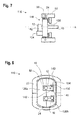
Figure 1 shows a schematic sectional view of a fluid line having a conventional flange with a positioning pin; -
Figure 2 shows a schematic sectional view of an assembly according to the invention having a vehicle air conditioning system seal according to the invention in a first embodiment; -
Figure 3 shows a plan view of the assembly fromFigure 2 ; -
Figures 4 to 6 schematically show mounting steps for the assembly fromFigure 2 ; -
Figure 7 shows a schematic sectional view of an assembly according to the invention having a vehicle air conditioning system seal according to the invention in a second embodiment; and -
Figure 8 shows a plan view of the assembly fromFigure 7 . -
Figure 1 shows afluid line 10, which has at one end aflange 12 that is connected to thefluid line 10 in a rotationally fixed manner. A positioningpin 14 projects at a given point from an end face, facing away from the fluid line, of theflange 12. The positioningpin 14 serves, as conventionally known, to avoid incorrect mounting when connecting forward and return lines of refrigerant in a vehicle air conditioning system. -
Figures 2 and 3 show anassembly 16 according to the invention having a vehicle air conditioning system seal 18 (also referred to as "seal" for short in the following text) according to the invention.Figure 2 in this case shows a sectional view along the line II-II inFigure 3 . Theseal 18 seals aline leadthrough 20 for afluid line 10 in ahousing 22 of a vehicle air conditioning module. Thehousing 22 usually consists of a rigid plastics material. - The vehicle air conditioning module (not shown in more detail) is arranged for example on a vehicle-interior side of a bulkhead and is connected, via the
fluid line 10 extending through theleadthrough 20, to a further module of the same air conditioning system, which is located on the other side of the bulkhead in the engine compartment. Theseal 18 prevents the penetration of water and moisture from the engine compartment into the vehicle interior and into the interior of thehousing 22. - The
seal 18 consists here of aresilient sealing element 24 and of a rigidintermediate body 26 that is received within theresilient sealing element 24. In this example, theresilient sealing element 24 is produced as a one-piece body made of a suitable elastomer and has in this case a cylindricalcircumferential wall portion 27 which surrounds theintermediate body 26. - Formed in the rigid
intermediate body 26 is a leadthrough opening 28 through which thefluid line 10 extends. It is possible for a plurality ofleadthrough openings 28 to be present in theintermediate body 26, as is illustrated for example inFigures 3 and8 . However, it is also possible to provide only asingle leadthrough opening 28. - The
intermediate body 26 consists here of twoparts leadthrough opening 28 for each of thefluid lines 10, such that the twoparts fluid lines 10 so that each of thefluid lines 10 is surrounded by the inner wall of therespective leadthrough opening 28. - The
seal 18 is inserted into anopening 30 in thehousing 22, wherein thecircumferential wall portion 27 is located between theintermediate body 26 and the inner wall of theopening 30 in thehousing 22. The dimensions are selected such that theseal 18 is held in theopening 30 with a desired clamping force. - Provided in this case between the inner wall of the
leadthrough opening 28 in the rigidintermediate body 26 and the outer circumference of thefluid line 10 is a sealingmaterial 32 in order to create gas- and/or liquid-tight sealing of theleadthrough opening 28. However, the sealing material could also be formed by a portion of theresilient sealing element 24 of theseal 18, saidresilient sealing element 24 for example enclosing thefluid line 10 in a manner axially adjoining theintermediate body 26. - The
seal 18 has an anti-twist device which limits rotation of thefluid line 10 with respect to theintermediate body 26. In this case, provision is made of a seal-side structure 34 which interacts with a line-side structure 36 such that it is only possible to twist thefluid line 10 with respect to theintermediate body 26 through a maximum twist angle, which is for example of the order of 0.1° to 3°. - In the embodiment shown here, the seal-
side structure 34 is formed by a blind hole in theintermediate body 26, while the line-side structure 36 is formed by a fixing pin which engages in the blind hole. - The fixing pin is configured here as an extension of the
positioning pin 14 on theflange 12 on thefluid line 10. Thepositioning pin 14, provided as a mounting aid on theflange 12, is extended through theflange 12 and has a seal-side end which extends in a straight line from thepositioning pin 14 and which can engage as a fixing pin in the blind hole in theintermediate body 26. - It is desired for the fixing pin to fit in a form-fitting manner in the blind hole, but, on account of manufacturing tolerances, small gaps can remain, and so slight twisting within the maximum rotation angle is possible.
- As a result of the anti-twist device, rotational forces that occur when the flange connections are tightened on the
fluid lines 10 of the air conditioning system are transferred via the fixing pin to theintermediate body 26 and via the latter to thehousing 22 of the air conditioning module. Therefore, it is possible to tighten the connections between thefluid lines 10 with sufficiently large forces in order to achieve the required sealing even for the refrigerant R744, in the case of which higher pressures prevail in thefluid lines 10 than in the case of other refrigerants. -
Figures 4 to 6 show the mounting of theseal 18 on thehousing 22 and on the twofluid lines 10. - First of all, the
resilient sealing element 24 is pulled over theflange 12 onto thefluid lines 10 and the twoparts intermediate body 26 are put together around the fluid lines 10. Then, theresilient sealing element 24 is pushed over theintermediate body 26 such that thecircumferential wall portion 27 surrounds theintermediate body 26. - The fluid lines 10 and the
flanges 12 thereof are rotated such that the fixing pin of the line-side structure 36 can engage in the blind hole in the seal-side structure 34. In this position, theseal 18 is pushed onto theflanges 12. - Finally, the components thus mounted are inserted into the
housing 22. In this example, thehousing 22 is also formed in two parts, wherein two half-shell-like parts seal 18, are provided in the region of theopening 30. The parting plane of theparts housing 22 lies in this case perpendicularly to the parting plane of theintermediate body 26. It would also be possible to use a one-piece housing 22 and to push theseal 18, together with thefluid line 10 mounted therein, into theopening 30 in the housing. -
Figures 7 and 8 show a second embodiment of anassembly 116. Components that are already known from the first embodiment and are not changed or are only changed insignificantly retain their already introduced reference signs. - In contrast to the
assembly 16 that has just been described, in this case the seal-side structure 134 of the anti-twist device on theseal 118 consists of a protrusion that projects in the axial direction A from the surface of theintermediate body 126 and partially engages around theflange 12 on thefluid line 10. The protrusion defines a U-shaped recess in which one end of therectangular flange 12 is received. On account of this geometry, the seal-side structure 134 has twostop points 140 which are located in the inner side, facing theflange 12, of the protrusion and which come into contact with the outer circumference of theflange 12 in the event of twisting about the central axis M of the fluid line 10 (indicated inFigure 8 for the upper flange 12). The line-side structure 136 is formed in this example simply bystop surfaces 142 in the rectangular external contour of the flange 12 (in this case at or close to the corners of the flange 12), and further processing or special shaping of theflange 12 is not necessary. - It would also be possible to provide a single, pin-like protrusion only at the position of each of the two stop points 140. It would likewise be possible to allow the protrusion to extend around the
entire flange 12, or else to insert theflange 12 into a corresponding recess in theintermediate body 126. - The seal-
side structure 134 is arranged entirely on one of the twoparts intermediate body 126. - As in the first embodiment, there is preferably a form fit between the seal-
side structure 134 and the line-side structure 136, although small spaces can be accepted. Here, too, the preferred maximum rotation angle is within 0.1° to 3°. Twisting in both directions of rotation is thus only within manufacturing tolerances. - This form of anti-twist device can be used both for flanges with one fluid line and for flanges with a plurality of fluid lines (not illustrated).
Claims (10)
- Vehicle air conditioning system seal, which has a resilient sealing element (24) and a rigid intermediate body (26; 126) in which at least one leadthrough opening (28) for a fluid line (10) of the vehicle air conditioning system is formed, wherein provision is made of an anti-twist device which limits twisting of the fluid line (10) with respect to the vehicle air conditioning system seal (18; 118), wherein the anti-twist device comprises a seal-side structure (34; 134) which is provided on the intermediate body (26; 126) and can interact with a line-side structure (36; 136) which is formed on the fluid line (10), and the seal-side structure (34; 134) is configured such that the line-side structure (36; 136) comes into abutment against the seal-side structure (34; 134) at least when the fluid line (10) is twisted through a maximum twist angle with respect to the intermediate body (26; 126).
- Vehicle air conditioning system seal according to Claim 1, characterized in that the seal-side structure (34) is a blind hole in the intermediate body (26).
- Vehicle air conditioning system seal according to Claim 1, characterized in that the seal-side structure (134) has at least one stop point (140) formed on the intermediate body (126).
- Vehicle air conditioning system seal according to one of the preceding claims, characterized in that the intermediate body (26; 126) has a plurality of parts (26a, 26b; 126a, 126b) which are able to be put together around the fluid line (10) such that they engage around the fluid line (10), wherein each of the parts (26a, 26b; 126a, 126b) defines a portion of the inner wall of the leadthrough opening (28).
- Assembly having a vehicle air conditioning system seal, in particular according to one of the preceding claims, which comprises at least one leadthrough opening (28) and a fluid line (10), extending through the leadthrough opening (28), of the air conditioning system, wherein the vehicle air conditioning system seal (18; 118) has a resilient sealing element (24) and a rigid intermediate body (26; 126), and wherein provision is made of an anti-twist device which limits twisting of the fluid line (10) with respect to the vehicle air conditioning system seal (18; 118), and the anti-twist device comprises a seal-side structure (34; 134) on the intermediate body (26; 126) and a line-side structure (36; 136) formed on the fluid line (10), wherein the line-side structure (36; 136) comes into abutment against the seal-side structure (34; 134) at least when the fluid line (10) is twisted through a maximum twist angle with respect to the intermediate body (26; 126).
- Assembly according to Claim 5, characterized in that the seal-side structure (34) is formed by a blind hole in the intermediate body (26) and the line-side structure (36) is formed by a fixing pin that engages in the blind hole.
- Assembly according to Claim 6, characterized in that the fixing pin is an extended portion, directed towards the intermediate body (26), of a positioning pin (14) on a flange (12) of the fluid line (10).
- Assembly according to Claim 5, characterized in that the seal-side structure (134) comprises at least one stop point (140) and the line-side structure (136) comprises at least one stop surface (142) which comes into contact with the stop point (140) at least when the fluid line (10) is twisted through the maximum twist angle with respect to the intermediate body (126).
- Assembly according to Claim 8, characterized in that the seal-side structure (134) comprises a recess and/or a protrusion with at least two wall surfaces on an end face of the intermediate body (126), wherein the stop points (140) are located in the wall surfaces.
- Assembly according to either of Claims 8 and 9, characterized in that the seal-side structure (134) and the line-side structure (136) form a form-fitting connection at least over a portion of the circumference of the flange (12) on the fluid line (10).
Applications Claiming Priority (1)
| Application Number | Priority Date | Filing Date | Title |
|---|---|---|---|
| DE102014113926.7A DE102014113926A1 (en) | 2014-09-25 | 2014-09-25 | Vehicle air conditioning system gasket and assembly with a vehicle air conditioning system gasket |
Publications (2)
| Publication Number | Publication Date |
|---|---|
| EP3000633A1 true EP3000633A1 (en) | 2016-03-30 |
| EP3000633B1 EP3000633B1 (en) | 2018-10-17 |
Family
ID=54198991
Family Applications (1)
| Application Number | Title | Priority Date | Filing Date |
|---|---|---|---|
| EP15186331.3A Not-in-force EP3000633B1 (en) | 2014-09-25 | 2015-09-22 | Vehicle air conditioning system seal and assembly having a vehicle air conditioning system seal |
Country Status (2)
| Country | Link |
|---|---|
| EP (1) | EP3000633B1 (en) |
| DE (1) | DE102014113926A1 (en) |
Families Citing this family (1)
| Publication number | Priority date | Publication date | Assignee | Title |
|---|---|---|---|---|
| DE102024111888A1 (en) * | 2024-04-29 | 2025-10-30 | Audi Aktiengesellschaft | Block connection arrangement with one-piece locking projection for a refrigeration system of a motor vehicle and refrigeration system with such a block connection arrangement |
Citations (3)
| Publication number | Priority date | Publication date | Assignee | Title |
|---|---|---|---|---|
| JPH01289714A (en) * | 1988-05-16 | 1989-11-21 | Hitachi Ltd | Piping connection structure for automobile |
| US20090250559A1 (en) * | 2008-04-03 | 2009-10-08 | Benoit Thomas A | Tube holding block assembly |
| FR2941518A1 (en) * | 2009-01-26 | 2010-07-30 | Valeo Systemes Thermiques | Heating, ventilation and/or air-conditioning installation for use in motor vehicle, has connector placed in housing, and assembly device with limit unit to limit displacement of connector in rotation inside housing |
-
2014
- 2014-09-25 DE DE102014113926.7A patent/DE102014113926A1/en not_active Withdrawn
-
2015
- 2015-09-22 EP EP15186331.3A patent/EP3000633B1/en not_active Not-in-force
Patent Citations (3)
| Publication number | Priority date | Publication date | Assignee | Title |
|---|---|---|---|---|
| JPH01289714A (en) * | 1988-05-16 | 1989-11-21 | Hitachi Ltd | Piping connection structure for automobile |
| US20090250559A1 (en) * | 2008-04-03 | 2009-10-08 | Benoit Thomas A | Tube holding block assembly |
| FR2941518A1 (en) * | 2009-01-26 | 2010-07-30 | Valeo Systemes Thermiques | Heating, ventilation and/or air-conditioning installation for use in motor vehicle, has connector placed in housing, and assembly device with limit unit to limit displacement of connector in rotation inside housing |
Also Published As
| Publication number | Publication date |
|---|---|
| EP3000633B1 (en) | 2018-10-17 |
| DE102014113926A1 (en) | 2016-03-31 |
Similar Documents
| Publication | Publication Date | Title |
|---|---|---|
| US9745926B2 (en) | Fluid line coupling | |
| US9784281B2 (en) | Exhaust-gas turbocharger | |
| US10711922B2 (en) | Wall feed-through element for a fluid line and wall feed-through | |
| US20030214130A1 (en) | Air conditioning block fitting with two surface sealing | |
| ES2263857T3 (en) | UNION PROVISION FOR FRIDGE AGENT PIPES. | |
| KR101906654B1 (en) | Method for producing a plug-in connector, and plug-in connector | |
| EP3000632B1 (en) | Vehicle air-conditioning-system-module seal and assembly with a vehicle air-conditioning-system-module seal | |
| US20170219139A1 (en) | Rotatable axially securing and pressure-resistant line connection | |
| US10036390B2 (en) | Pump unit | |
| US10305349B2 (en) | Actuator with latching connection | |
| EP3000633B1 (en) | Vehicle air conditioning system seal and assembly having a vehicle air conditioning system seal | |
| US20130134707A1 (en) | Pipe coupling for the fluid-tight attachment of components in an air conditioning system | |
| US7066208B2 (en) | Hydraulic accumulator | |
| KR101820570B1 (en) | Screw connection device for connecting two pipes | |
| JP2008256091A (en) | Piping joint | |
| KR101539320B1 (en) | Carbon seals for automotive air compressor compartment | |
| JPH01289714A (en) | Piping connection structure for automobile | |
| US10539146B2 (en) | Centrifugal pump | |
| JP2007092773A (en) | Assembling structure for eye coupling | |
| EP3652070B1 (en) | Fuel tank communication systems | |
| CN223677320U (en) | Rivet joint and cooling system | |
| US12379053B2 (en) | Connecting device for a sealed exchange of fluid between two components, connecting system and brake system | |
| CN104566882A (en) | Air-conditioner pipe | |
| JP2024542380A (en) | Pump device with screw plug | |
| US20210148452A1 (en) | Sealing surface having leak-proof passage of an oil channel |
Legal Events
| Date | Code | Title | Description |
|---|---|---|---|
| PUAI | Public reference made under article 153(3) epc to a published international application that has entered the european phase |
Free format text: ORIGINAL CODE: 0009012 |
|
| AK | Designated contracting states |
Kind code of ref document: A1 Designated state(s): AL AT BE BG CH CY CZ DE DK EE ES FI FR GB GR HR HU IE IS IT LI LT LU LV MC MK MT NL NO PL PT RO RS SE SI SK SM TR |
|
| AX | Request for extension of the european patent |
Extension state: BA ME |
|
| 17P | Request for examination filed |
Effective date: 20160930 |
|
| RBV | Designated contracting states (corrected) |
Designated state(s): AL AT BE BG CH CY CZ DE DK EE ES FI FR GB GR HR HU IE IS IT LI LT LU LV MC MK MT NL NO PL PT RO RS SE SI SK SM TR |
|
| GRAP | Despatch of communication of intention to grant a patent |
Free format text: ORIGINAL CODE: EPIDOSNIGR1 |
|
| STAA | Information on the status of an ep patent application or granted ep patent |
Free format text: STATUS: GRANT OF PATENT IS INTENDED |
|
| RIC1 | Information provided on ipc code assigned before grant |
Ipc: F16L 41/08 20060101ALI20180418BHEP Ipc: B60H 1/00 20060101AFI20180418BHEP |
|
| INTG | Intention to grant announced |
Effective date: 20180507 |
|
| GRAS | Grant fee paid |
Free format text: ORIGINAL CODE: EPIDOSNIGR3 |
|
| GRAA | (expected) grant |
Free format text: ORIGINAL CODE: 0009210 |
|
| STAA | Information on the status of an ep patent application or granted ep patent |
Free format text: STATUS: THE PATENT HAS BEEN GRANTED |
|
| AK | Designated contracting states |
Kind code of ref document: B1 Designated state(s): AL AT BE BG CH CY CZ DE DK EE ES FI FR GB GR HR HU IE IS IT LI LT LU LV MC MK MT NL NO PL PT RO RS SE SI SK SM TR |
|
| REG | Reference to a national code |
Ref country code: GB Ref legal event code: FG4D |
|
| REG | Reference to a national code |
Ref country code: CH Ref legal event code: EP |
|
| REG | Reference to a national code |
Ref country code: IE Ref legal event code: FG4D |
|
| REG | Reference to a national code |
Ref country code: DE Ref legal event code: R096 Ref document number: 602015018196 Country of ref document: DE Ref country code: AT Ref legal event code: REF Ref document number: 1053560 Country of ref document: AT Kind code of ref document: T Effective date: 20181115 |
|
| REG | Reference to a national code |
Ref country code: NL Ref legal event code: MP Effective date: 20181017 |
|
| REG | Reference to a national code |
Ref country code: LT Ref legal event code: MG4D |
|
| REG | Reference to a national code |
Ref country code: AT Ref legal event code: MK05 Ref document number: 1053560 Country of ref document: AT Kind code of ref document: T Effective date: 20181017 |
|
| PG25 | Lapsed in a contracting state [announced via postgrant information from national office to epo] |
Ref country code: NL Free format text: LAPSE BECAUSE OF FAILURE TO SUBMIT A TRANSLATION OF THE DESCRIPTION OR TO PAY THE FEE WITHIN THE PRESCRIBED TIME-LIMIT Effective date: 20181017 |
|
| PG25 | Lapsed in a contracting state [announced via postgrant information from national office to epo] |
Ref country code: FI Free format text: LAPSE BECAUSE OF FAILURE TO SUBMIT A TRANSLATION OF THE DESCRIPTION OR TO PAY THE FEE WITHIN THE PRESCRIBED TIME-LIMIT Effective date: 20181017 Ref country code: IS Free format text: LAPSE BECAUSE OF FAILURE TO SUBMIT A TRANSLATION OF THE DESCRIPTION OR TO PAY THE FEE WITHIN THE PRESCRIBED TIME-LIMIT Effective date: 20190217 Ref country code: BG Free format text: LAPSE BECAUSE OF FAILURE TO SUBMIT A TRANSLATION OF THE DESCRIPTION OR TO PAY THE FEE WITHIN THE PRESCRIBED TIME-LIMIT Effective date: 20190117 Ref country code: PL Free format text: LAPSE BECAUSE OF FAILURE TO SUBMIT A TRANSLATION OF THE DESCRIPTION OR TO PAY THE FEE WITHIN THE PRESCRIBED TIME-LIMIT Effective date: 20181017 Ref country code: HR Free format text: LAPSE BECAUSE OF FAILURE TO SUBMIT A TRANSLATION OF THE DESCRIPTION OR TO PAY THE FEE WITHIN THE PRESCRIBED TIME-LIMIT Effective date: 20181017 Ref country code: NO Free format text: LAPSE BECAUSE OF FAILURE TO SUBMIT A TRANSLATION OF THE DESCRIPTION OR TO PAY THE FEE WITHIN THE PRESCRIBED TIME-LIMIT Effective date: 20190117 Ref country code: LT Free format text: LAPSE BECAUSE OF FAILURE TO SUBMIT A TRANSLATION OF THE DESCRIPTION OR TO PAY THE FEE WITHIN THE PRESCRIBED TIME-LIMIT Effective date: 20181017 Ref country code: ES Free format text: LAPSE BECAUSE OF FAILURE TO SUBMIT A TRANSLATION OF THE DESCRIPTION OR TO PAY THE FEE WITHIN THE PRESCRIBED TIME-LIMIT Effective date: 20181017 Ref country code: AT Free format text: LAPSE BECAUSE OF FAILURE TO SUBMIT A TRANSLATION OF THE DESCRIPTION OR TO PAY THE FEE WITHIN THE PRESCRIBED TIME-LIMIT Effective date: 20181017 Ref country code: LV Free format text: LAPSE BECAUSE OF FAILURE TO SUBMIT A TRANSLATION OF THE DESCRIPTION OR TO PAY THE FEE WITHIN THE PRESCRIBED TIME-LIMIT Effective date: 20181017 |
|
| PG25 | Lapsed in a contracting state [announced via postgrant information from national office to epo] |
Ref country code: SE Free format text: LAPSE BECAUSE OF FAILURE TO SUBMIT A TRANSLATION OF THE DESCRIPTION OR TO PAY THE FEE WITHIN THE PRESCRIBED TIME-LIMIT Effective date: 20181017 Ref country code: AL Free format text: LAPSE BECAUSE OF FAILURE TO SUBMIT A TRANSLATION OF THE DESCRIPTION OR TO PAY THE FEE WITHIN THE PRESCRIBED TIME-LIMIT Effective date: 20181017 Ref country code: RS Free format text: LAPSE BECAUSE OF FAILURE TO SUBMIT A TRANSLATION OF THE DESCRIPTION OR TO PAY THE FEE WITHIN THE PRESCRIBED TIME-LIMIT Effective date: 20181017 Ref country code: GR Free format text: LAPSE BECAUSE OF FAILURE TO SUBMIT A TRANSLATION OF THE DESCRIPTION OR TO PAY THE FEE WITHIN THE PRESCRIBED TIME-LIMIT Effective date: 20190118 Ref country code: PT Free format text: LAPSE BECAUSE OF FAILURE TO SUBMIT A TRANSLATION OF THE DESCRIPTION OR TO PAY THE FEE WITHIN THE PRESCRIBED TIME-LIMIT Effective date: 20190217 |
|
| REG | Reference to a national code |
Ref country code: DE Ref legal event code: R097 Ref document number: 602015018196 Country of ref document: DE |
|
| PG25 | Lapsed in a contracting state [announced via postgrant information from national office to epo] |
Ref country code: IT Free format text: LAPSE BECAUSE OF FAILURE TO SUBMIT A TRANSLATION OF THE DESCRIPTION OR TO PAY THE FEE WITHIN THE PRESCRIBED TIME-LIMIT Effective date: 20181017 Ref country code: DK Free format text: LAPSE BECAUSE OF FAILURE TO SUBMIT A TRANSLATION OF THE DESCRIPTION OR TO PAY THE FEE WITHIN THE PRESCRIBED TIME-LIMIT Effective date: 20181017 Ref country code: CZ Free format text: LAPSE BECAUSE OF FAILURE TO SUBMIT A TRANSLATION OF THE DESCRIPTION OR TO PAY THE FEE WITHIN THE PRESCRIBED TIME-LIMIT Effective date: 20181017 |
|
| PLBE | No opposition filed within time limit |
Free format text: ORIGINAL CODE: 0009261 |
|
| STAA | Information on the status of an ep patent application or granted ep patent |
Free format text: STATUS: NO OPPOSITION FILED WITHIN TIME LIMIT |
|
| PG25 | Lapsed in a contracting state [announced via postgrant information from national office to epo] |
Ref country code: RO Free format text: LAPSE BECAUSE OF FAILURE TO SUBMIT A TRANSLATION OF THE DESCRIPTION OR TO PAY THE FEE WITHIN THE PRESCRIBED TIME-LIMIT Effective date: 20181017 Ref country code: SK Free format text: LAPSE BECAUSE OF FAILURE TO SUBMIT A TRANSLATION OF THE DESCRIPTION OR TO PAY THE FEE WITHIN THE PRESCRIBED TIME-LIMIT Effective date: 20181017 Ref country code: SM Free format text: LAPSE BECAUSE OF FAILURE TO SUBMIT A TRANSLATION OF THE DESCRIPTION OR TO PAY THE FEE WITHIN THE PRESCRIBED TIME-LIMIT Effective date: 20181017 Ref country code: EE Free format text: LAPSE BECAUSE OF FAILURE TO SUBMIT A TRANSLATION OF THE DESCRIPTION OR TO PAY THE FEE WITHIN THE PRESCRIBED TIME-LIMIT Effective date: 20181017 |
|
| 26N | No opposition filed |
Effective date: 20190718 |
|
| PG25 | Lapsed in a contracting state [announced via postgrant information from national office to epo] |
Ref country code: SI Free format text: LAPSE BECAUSE OF FAILURE TO SUBMIT A TRANSLATION OF THE DESCRIPTION OR TO PAY THE FEE WITHIN THE PRESCRIBED TIME-LIMIT Effective date: 20181017 |
|
| PGFP | Annual fee paid to national office [announced via postgrant information from national office to epo] |
Ref country code: FR Payment date: 20190930 Year of fee payment: 5 |
|
| PG25 | Lapsed in a contracting state [announced via postgrant information from national office to epo] |
Ref country code: TR Free format text: LAPSE BECAUSE OF FAILURE TO SUBMIT A TRANSLATION OF THE DESCRIPTION OR TO PAY THE FEE WITHIN THE PRESCRIBED TIME-LIMIT Effective date: 20181017 |
|
| PG25 | Lapsed in a contracting state [announced via postgrant information from national office to epo] |
Ref country code: MC Free format text: LAPSE BECAUSE OF FAILURE TO SUBMIT A TRANSLATION OF THE DESCRIPTION OR TO PAY THE FEE WITHIN THE PRESCRIBED TIME-LIMIT Effective date: 20181017 |
|
| REG | Reference to a national code |
Ref country code: CH Ref legal event code: PL |
|
| PG25 | Lapsed in a contracting state [announced via postgrant information from national office to epo] |
Ref country code: IE Free format text: LAPSE BECAUSE OF NON-PAYMENT OF DUE FEES Effective date: 20190922 Ref country code: CH Free format text: LAPSE BECAUSE OF NON-PAYMENT OF DUE FEES Effective date: 20190930 Ref country code: LU Free format text: LAPSE BECAUSE OF NON-PAYMENT OF DUE FEES Effective date: 20190922 Ref country code: LI Free format text: LAPSE BECAUSE OF NON-PAYMENT OF DUE FEES Effective date: 20190930 |
|
| REG | Reference to a national code |
Ref country code: BE Ref legal event code: MM Effective date: 20190930 |
|
| PG25 | Lapsed in a contracting state [announced via postgrant information from national office to epo] |
Ref country code: BE Free format text: LAPSE BECAUSE OF NON-PAYMENT OF DUE FEES Effective date: 20190930 |
|
| GBPC | Gb: european patent ceased through non-payment of renewal fee |
Effective date: 20190922 |
|
| PG25 | Lapsed in a contracting state [announced via postgrant information from national office to epo] |
Ref country code: GB Free format text: LAPSE BECAUSE OF NON-PAYMENT OF DUE FEES Effective date: 20190922 |
|
| PGFP | Annual fee paid to national office [announced via postgrant information from national office to epo] |
Ref country code: DE Payment date: 20200910 Year of fee payment: 6 |
|
| PG25 | Lapsed in a contracting state [announced via postgrant information from national office to epo] |
Ref country code: CY Free format text: LAPSE BECAUSE OF FAILURE TO SUBMIT A TRANSLATION OF THE DESCRIPTION OR TO PAY THE FEE WITHIN THE PRESCRIBED TIME-LIMIT Effective date: 20181017 |
|
| PG25 | Lapsed in a contracting state [announced via postgrant information from national office to epo] |
Ref country code: HU Free format text: LAPSE BECAUSE OF FAILURE TO SUBMIT A TRANSLATION OF THE DESCRIPTION OR TO PAY THE FEE WITHIN THE PRESCRIBED TIME-LIMIT; INVALID AB INITIO Effective date: 20150922 Ref country code: MT Free format text: LAPSE BECAUSE OF FAILURE TO SUBMIT A TRANSLATION OF THE DESCRIPTION OR TO PAY THE FEE WITHIN THE PRESCRIBED TIME-LIMIT Effective date: 20181017 Ref country code: FR Free format text: LAPSE BECAUSE OF NON-PAYMENT OF DUE FEES Effective date: 20200930 |
|
| REG | Reference to a national code |
Ref country code: DE Ref legal event code: R119 Ref document number: 602015018196 Country of ref document: DE |
|
| PG25 | Lapsed in a contracting state [announced via postgrant information from national office to epo] |
Ref country code: MK Free format text: LAPSE BECAUSE OF FAILURE TO SUBMIT A TRANSLATION OF THE DESCRIPTION OR TO PAY THE FEE WITHIN THE PRESCRIBED TIME-LIMIT Effective date: 20181017 |
|
| PG25 | Lapsed in a contracting state [announced via postgrant information from national office to epo] |
Ref country code: DE Free format text: LAPSE BECAUSE OF NON-PAYMENT OF DUE FEES Effective date: 20220401 |
|
| P01 | Opt-out of the competence of the unified patent court (upc) registered |
Effective date: 20230629 |