EP3000537A1 - Washing position confirmation device, fluid delivery position confirmation device, washing position confirmation system, and fluid delivery position confirmation method - Google Patents
Washing position confirmation device, fluid delivery position confirmation device, washing position confirmation system, and fluid delivery position confirmation method Download PDFInfo
- Publication number
- EP3000537A1 EP3000537A1 EP14800475.7A EP14800475A EP3000537A1 EP 3000537 A1 EP3000537 A1 EP 3000537A1 EP 14800475 A EP14800475 A EP 14800475A EP 3000537 A1 EP3000537 A1 EP 3000537A1
- Authority
- EP
- European Patent Office
- Prior art keywords
- fluid
- light source
- light
- joint member
- source section
- Prior art date
- Legal status (The legal status is an assumption and is not a legal conclusion. Google has not performed a legal analysis and makes no representation as to the accuracy of the status listed.)
- Granted
Links
Images


Classifications
-
- B—PERFORMING OPERATIONS; TRANSPORTING
- B08—CLEANING
- B08B—CLEANING IN GENERAL; PREVENTION OF FOULING IN GENERAL
- B08B5/00—Cleaning by methods involving the use of air flow or gas flow
- B08B5/02—Cleaning by the force of jets, e.g. blowing-out cavities
-
- B—PERFORMING OPERATIONS; TRANSPORTING
- B05—SPRAYING OR ATOMISING IN GENERAL; APPLYING FLUENT MATERIALS TO SURFACES, IN GENERAL
- B05B—SPRAYING APPARATUS; ATOMISING APPARATUS; NOZZLES
- B05B1/00—Nozzles, spray heads or other outlets, with or without auxiliary devices such as valves, heating means
- B05B1/005—Nozzles or other outlets specially adapted for discharging one or more gases
-
- B—PERFORMING OPERATIONS; TRANSPORTING
- B05—SPRAYING OR ATOMISING IN GENERAL; APPLYING FLUENT MATERIALS TO SURFACES, IN GENERAL
- B05B—SPRAYING APPARATUS; ATOMISING APPARATUS; NOZZLES
- B05B12/00—Arrangements for controlling delivery; Arrangements for controlling the spray area
- B05B12/08—Arrangements for controlling delivery; Arrangements for controlling the spray area responsive to condition of liquid or other fluent material to be discharged, of ambient medium or of target ; responsive to condition of spray devices or of supply means, e.g. pipes, pumps or their drive means
- B05B12/12—Arrangements for controlling delivery; Arrangements for controlling the spray area responsive to condition of liquid or other fluent material to be discharged, of ambient medium or of target ; responsive to condition of spray devices or of supply means, e.g. pipes, pumps or their drive means responsive to conditions of ambient medium or target, e.g. humidity, temperature position or movement of the target relative to the spray apparatus
- B05B12/122—Arrangements for controlling delivery; Arrangements for controlling the spray area responsive to condition of liquid or other fluent material to be discharged, of ambient medium or of target ; responsive to condition of spray devices or of supply means, e.g. pipes, pumps or their drive means responsive to conditions of ambient medium or target, e.g. humidity, temperature position or movement of the target relative to the spray apparatus responsive to presence or shape of target
-
- B—PERFORMING OPERATIONS; TRANSPORTING
- B08—CLEANING
- B08B—CLEANING IN GENERAL; PREVENTION OF FOULING IN GENERAL
- B08B13/00—Accessories or details of general applicability for machines or apparatus for cleaning
-
- B—PERFORMING OPERATIONS; TRANSPORTING
- B05—SPRAYING OR ATOMISING IN GENERAL; APPLYING FLUENT MATERIALS TO SURFACES, IN GENERAL
- B05B—SPRAYING APPARATUS; ATOMISING APPARATUS; NOZZLES
- B05B1/00—Nozzles, spray heads or other outlets, with or without auxiliary devices such as valves, heating means
- B05B1/02—Nozzles, spray heads or other outlets, with or without auxiliary devices such as valves, heating means designed to produce a jet, spray, or other discharge of particular shape or nature, e.g. in single drops, or having an outlet of particular shape
- B05B1/04—Nozzles, spray heads or other outlets, with or without auxiliary devices such as valves, heating means designed to produce a jet, spray, or other discharge of particular shape or nature, e.g. in single drops, or having an outlet of particular shape in flat form, e.g. fan-like, sheet-like
- B05B1/042—Outlets having two planes of symmetry perpendicular to each other, one of them defining the plane of the jet
Definitions
- the present invention relates to a cleaning position checking device included in an air-cleaning device for cleaning a cleaning-target object by blowing a fluid to the cleaning-target object.
- Patent Literature 1 discloses a nozzle having a light which nozzle is provided at an end of a flexible tube. The nozzle is configured such that (i) a light source is provided inside the nozzle so that light is emitted through the nozzle and (ii) a fluid is ejected from the flexible tube through the nozzle.
- Patent Literature 2 discloses an ejection reaching position checking jig for, before ejection of a substance through a nozzle, checking a position which the substance to be ejected is to reach.
- the jig is removably attached to the nozzle and has a light emitting material which, in a state where the jig is attached to the nozzle, emits light in a direction identical to that of a trajectory of the substance ejected through the nozzle. This allows a position which light from the light emitting material reaches to match a position which the substance ejected through the nozzle actually reaches. Therefore, before ejecting the substance, it is possible to check the position which the substance to be ejected is to reach, by checking light emitted from the light emitting material.
- Patent Literature 1 is configured such that (i) the light source is provided inside the nozzle and (ii) the slit is formed in the inner circumferential surface of the nozzle so that a fluid passes therethrough. It is therefore necessary to process the nozzle so as to have such a configuration. Moreover, since a commercially available slit nozzle or a porous nozzle has a flow path whose width is wide, it is not possible to fit a light source into such a nozzle. This causes usable nozzles to be limited. Therefore, there is a problem that the technique of Patent Literature 1 lacks versatility.
- Patent Literature 2 has a problem that it is not possible to check, during ejection of the substance, a position which the substance reaches. Furthermore, since a shape of the jig is determined in accordance with a shape of the nozzle, nozzles for which the jig can be used are limited. Therefore, the technique of Patent Literature 2 lacks versatility.
- the present invention has been made in view of the above problems, and an object of the present invention is to provide a cleaning position checking device, a fluid reaching position checking device, a cleaning position checking system, and a fluid reaching position checking method, each of which is highly versatile and makes it possible to easily check a position that a fluid to be blown is to reach.
- a cleaning position checking device of the present invention is a cleaning position checking device, provided between a fluid supply section and a nozzle having a hole through which a fluid supplied from the fluid supply section is ejected so that an cleaned object is cleaned with the fluid, for checking a position which the fluid to be ejected is to reach,
- the cleaning position checking device including: a joint member having a tubular shape, the joint member having (i) an inlet part through which the fluid flows in the joint member and (ii) an outlet part through which the fluid flows out of the joint member; and a holder having (a) a first opening through which a light source section is provided and (b) a light source section provided space therein in which the light source section is held so as to emit light toward the outlet part.
- the present invention is an invention which is highly versatile and which makes it possible to easily check a position that a fluid to be blown is to reach.
- Fig. 1 is a view illustrating an example air-cleaning device in accordance with an embodiment of the present invention.
- the air-cleaning device is a device which blows air to a cleaning-target object (cleaned object), which is retained at a predetermined height by a support, so as to eliminate dust and the like from the cleaning-target object.
- an air-cleaning device (cleaning position checking system) 1 includes an air supply section (fluid supply section) 100 which supplies pressurized air, an electromagnetic valve 30, a joint 40, a nozzle 50, a power source 10, a control device 20, and a dust collecting duct 70. Air outputted from the air supply section 100 passes through the electromagnetic valve 30 and the joint 40 in this order, and reaches the nozzle 50. The air is then blown to a cleaning-target object 60 through the nozzle 50. Dust eliminated from the cleaning-target object 60 by blowing air to the cleaning-target object 60 is collected by a dust collector (not illustrated) through the dust collecting duct 70.
- the air supply section 100 can further include a regulator for regulating a pressure of air to a predetermined pressure, a filter for eliminating a mist from air, and the like.
- the present embodiment will take, as an example, a case where air is blown to a cleaning-target object.
- the present embodiment is not limited to air, and any fluid including gas, such as nitrogen and argon, and liquids, such as water, can be alternatively employed.
- the control device 20 is connected to the electromagnetic valve 30 and a light source 80 which is provided inside the joint (cleaning position checking device) 40 provided between the nozzle 50 and the electromagnetic valve 30.
- the control device 20 controls (i) opening and closing of the electromagnetic valve 30 and (ii) the light source 80.
- the power source 10 supplies electric power to the control device 20, the electromagnetic valve 30, and the light source 80.
- the joint 40 will be described in detail with reference to Figs. 2 and 3 .
- Fig. 2 is a perspective view illustrating an inside of a joint.
- Fig. 3 is an enlarged view illustrating the inside of the joint.
- the joint 40 includes (i) a joint member 41 having a substantially cylindrical shape (tubular shape) and (ii) a holder 43 formed inside the joint member 41.
- the joint member 41 has (a) an inlet part 41b through which a fluid flows in the joint member 41 and (b) an outlet part 41a through which the fluid flows out of the joint member 41.
- the joint member 41 is configured such that (i) the inlet part 41b is connected to a side of the electromagnetic valve 30 through which side air is discharged and (ii) the outlet part 41a is connected to the nozzle 50.
- a thread groove is formed in an area of an inner circumferential surface of the joint member 41 which area extends, by a predetermined length, from the inlet part 41b.
- a tube which the electromagnetic valve 30 has and whose outer circumferential surface has therein a thread groove (outlet part of the electromagnetic valve 30) is screwed into the inlet part 41b.
- a thread groove is formed in an area of the inner circumferential surface of the joint member 41 which area extends, by a predetermined length, from the outlet part 41a.
- a tube which the nozzle 50 has and whose outer circumferential surface has therein a thread groove (inlet part of the nozzle 50) is screwed into the outlet part 41a.
- the holder 43 is fixed to the inner circumferential surface of the joint member 41.
- the holder 43 includes (i) a member (cylindrical member) 43f which has a cylindrical shape and which has an opening (first opening) 43a that faces the outlet part 41a of the joint member 41 and (ii) a cap 90 which covers the opening 43a.
- An outer diameter of the cylindrical member 43f is smaller than an inner diameter of the joint member 41. This allows, between the joint member 41 and the holder 43, air which has flowed in the joint member 41 through the inlet part 41b to flow toward the outlet part 41a.
- the shape of the cylindrical member 43f is not limited to the cylindrical shape and can alternatively have any shape.
- the cylindrical member 43f has a light source section provided space 43c in which the light source 80 is held. Specifically, the cylindrical member 43f successively has a first step part 43d and a second step part 43e on its inner circumferential surface on an inner side of the opening 43a. The first and second step parts 43d and 43e cause an inner diameter of the cylindrical member 43f to be smaller in part.
- the first step part 43d which is closer to the opening 43a than the second step part 43e, has a first contact surface 43d1 which extends in a radial direction.
- An edge of the cap 90 which covers the opening 43a of the cylindrical member 43f and which causes the light source 80 to be contained in the light source section provided space 43c, is in contact with the first contact surface 43d1.
- the second step part 43e which is further from the opening 43a that the first step part 43d, has a second contact surface 43e1 which extends in the radial direction.
- a back surface of the flange part 80a is in contact with the second contact surface 43e1.
- An inner diameter of the cap 90 is slightly smaller than an outer diameter of the flange part 80a of the light source 80, and is large enough to cover a light emitting part, other than the flange part 80a, of the light source 80.
- a distance between the first contact surface 43d1 and the second contact surface 43e1 is substantially equal to a thickness of the flange part 80a of the light source 80. Therefore, in a case where (i) the light source 80 is inserted into the cylindrical member 43f and (ii) the cap 90 is fitted to the opening 43a, the back surface of the flange part 80a of the light source 80 is supported by the second contact surface 43e1, and a front surface of the flange part 80a is supported by the edge of the cap 90. This allows the light source 80 to be positioned.
- a light axis of the light source 80 corresponds to a direction of a fluid flowing from the inlet part 41 b to the outlet part 41 a.
- the cap 90 can be arranged so as to have a high light-transmitting property by applying a solvent or the like on an outer surface of the cap 90. Further, the cap 90 can be processed into a lens shape so as to collect light emitted from the light source 80. A gap between the cap 90 and the cylindrical member 43f is sealed by a sealing member or a packing so as to prevent leakage of air. This also prevents external air from entering the joint member 41.
- the joint 40 has a through-hole (second opening) 43b.
- the through-hole 43b is located on an end of the space, in which the light source 80 is provided, of the cylindrical member 43f which end is different from an end at which the opening 43a is provided, and extends from an inside of the cylindrical member 43f to an outside of the joint member 41.
- the light source 80 is connected to the control device 20 and the power source 10 through the through-hole 43b.
- the light source 80 only needs to be one, such as an LED and a laser, that emits light traveling straight.
- the LED is not limited to a monochromatic LED, and can be alternatively a full-color LED or a color LED.
- a light source 80A which is a full-color LED having a plurality of LED chips that emit light of respective different colors can be provided inside the holder 43.
- a pressure sensor or the like is provided inside the nozzle 50, and the control device 20 controls the light source 80A to change colors depending on a change in pressure in the nozzle 50.
- the control device 20 controls the light source 80A to emit blue light. In a case where the value of the pressure is low, the control device 20 controls the light source 80A to emit green light. In a case where the value of the pressure is high, the control device 20 controls the light source 80A to emit red light.
- a photoelectric sensor which detects an object with use of light can be employed instead of the light source 80.
- the photoelectric sensor includes (i) a light emitting section (light source section) 81a which emits light and (ii) a light receiving section 81b which receives light.
- the control device 20 controls (i) the photoelectric sensor to detect the cleaning-target object 60 depending on whether or not the receiving section 81b detects light from the light emitting section 81a and (ii) air to be blown to the cleaning-target object 60.
- the control device 20 controls the electromagnetic valve 30 to be open so that air is blown to the cleaning-target object 60.
- the control device 20 controls the electromagnetic valve 30 to be closed so that a blow of the air is stopped. That is, supply of the air from the air supply section 100 to the nozzle 50 is stopped.
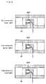
- the photoelectric sensor can be configured such that the light emitting section 81a and the light receiving section 81b are integrated with each other as illustrated in (a) of Fig. 6 .
- the photoelectric sensor can be configured such that the light emitting section 81a and light receiving section 81b are separated from each other as illustrated in (b) of Fig. 6 . That is, according to an example illustrated in (a) of Fig. 6 , the light emitting section 81a and the light receiving section 81b are provided in the light source section provided space 43c. According to an example illustrated in (b) of Fig.
- the light emitting section 81 a is provided in the light source section provided space 43c, and the light receiving section 81b is provided at a position which is located outside the joint 40 and which is located on a path along which light from the light source 80 travels.
- the control device 20 controls the photoelectric sensor to detect the cleaning-target object 60 in a case where light from the light emitting section 81a is reflected by the cleaning-target object 60 and received by the light receiving section 81b.
- the light receiving section 81b is arranged so as not to receive light directly from the light emitting section 81a.
- a shielding plate is provided between the light emitting section 81a and the light receiving section 81b.
- the control device 20 controls the photoelectric sensor to detect the cleaning-target object 60 in a case where light from the light emitting section 81a is not received by the light receiving section 81b.
- the nozzle 50 has a shape of a cylinder whose end is tapered, that is, a diameter of the nozzle 50 becomes smaller toward an end of the nozzle 50.
- a slit (hole) is formed in the end of the nozzle 50. Air is discharged through the slit of the nozzle 50.
- Fig. 7 is a view illustrating an example nozzle. As illustrated in (a) of Fig. 7 , a nozzle 50A has a slit 52 having a rectangular shape. In a case where light from the light source 80 passes through the slit 52, light having a shape identical to that of the slit 52 is emitted. On the other hand, as illustrated in (b) of Fig.
- a nozzle 50B has a slit 53 having a substantially circular shape.
- light from the light source 80 passes through the slit 53, light having a shape identical to that of the slit 53 is emitted. Therefore, it is possible to visually check, by checking an irradiation pattern, an area to which air is to be blown.
- the shape of the nozzle only needs to be one that allows light from the light source 80 to reach the cleaning-target object 60.
- a flow path such as an inside of the nozzle or the inside of the joint, can be processed with mirror finish so as to be reflective.
- a reflective material can be used so that the flow path is reflective.
- the shape of the nozzle is not limited to a cylindrical shape.
- a nozzle 50C can be employed which has such a shape that a cylinder is bent in the middle thereof as illustrated in Fig. 8 .
- a reflective plate 51 is provided at such a bent part of the cylinder so as to reflect light from the light source 80 toward a slit.
- a joint 40 of the present embodiment is a device, provided between an air supply section 100 and a nozzle 50 having a hole through which air supplied from the air supply section 100 is ejected so that a cleaning-target object 60 is cleaned with the air, for checking a position which the air to be ejected is to reach, the joint 40 including: a joint member 41 having a tubular shape, the joint member 41 having (i) an inlet part 41b through which the air flows in the joint member 41 and (ii) an outlet part 41a through which the air flows out of the joint member 41; and the holder having (a) an opening 43a through which a light source 80 is inserted into the holder and (b) a light source section provided space 43c in which the light source 80 is held so as to emit light toward the outlet part 41a.
- the light source 80 in a case where the light source 80 is provided in the light source section provided space 43c, it is possible to cause light to travel in a direction in which air flows. This allows a user to visually check a position which air is to reach. Furthermore, since the light source is not provided to the nozzle unlike the conventional techniques, it is not necessary to process the nozzle, depending on a type of the nozzle, so that the light source can be provided to the nozzle. This allows the joint to be used in connection with various types of nozzles. It is therefore possible to easily check a position which air to be blown is to reach, and possible to improve versatility.
- the air-cleaning device 1 is provided to an automated machine which blows air to sequentially conveyed cleaning-target objects 60, it is possible to shorten a time to position the nozzle 50 and possible to simplify management of the nozzles 50, because a position which air is to reach is easily checked. Moreover, it is only necessary to adjust the nozzle 50 so that target positions on the cleaning-target objects 60 are irradiated with light. Further, it can be seen that the nozzle 50 is not displaced even during production. Therefore, no special technique is needed to conduct checking operation.
- the air-cleaning device 1 of the present embodiment it is possible to absolutely and quantitatively give an highly effective clean (that is, it is possible to blow air a predetermined time later the cleaning-target object 60 is irradiated with light) merely by bringing, without regard to the nozzle 50, the cleaning-target object 60 to a position which light reaches.
- the air-cleaning device 1 of the present embodiment can be configured so as to clean the cleaning-target object 60 by removing static electricity from the cleaning-target object 60.
- a fluid reaching position checking device ionizer
- ionizer is configured by providing an ion generating device to the inlet part 41b of the joint 40. With this, an ionized fluid (air) is ejected through the nozzle 50, so that static electricity is removed from the cleaned object. It is thus possible to prevent powder dust and the like from attaching to the cleaned object.
- the air-cleaning device 1 of the present embodiment is configured such that the light source 80 is provided inside the joint 40 having a linear shape.
- An air-cleaning device 1 of a variation is configured such that a light source 80 is provided to a bent joint.
- Fig. 9 is a view illustrating an example joint of a variation.
- a joint 40A has a joint member 41A which has a cylindrical shape and which is bent into an L shape. That is, the joint member 41A has a bent part 41d, a tube part 41e which linearly extends from the bent part 41d to an outlet part 41a, and a tube part 41f which linearly extends from the bend part 41d to an inlet part 41b.
- a nozzle 50 is connected to the outlet part 41a of the joint member 41A, and an electromagnetic valve 30 is connected to the inlet part 41b of the joint member 41A.
- the joint member 41A further has an opening (third opening) 41 c which is provided along a direction of a flow path formed by the tube part 41e and which faces the outlet part 41a.
- a holder 43A is fitted and fixed to the opening 41 c.
- the holder 43A and the joint 40A can be fixed to each other by screwing up overlapping parts of the holder 43A and of the joint 40A.
- the holder 43A and the joint 40A can be fixed to each other in such a manner that an outer circumferential surface of the holder 43A is supported by an annular rubber provided along an inner side of the opening of the joint 40A.
- the holder 43A is one that is obtained by increasing a size of the holder 43 illustrated in Fig. 2 in accordance with the opening of the joint.
- the shape of the joint is not limited to an L shape, and can be alternatively a T shape.
- the air-cleaning device 1 is not limited to such a configuration that the holder 43A and the joint 40A are fixed to each other.
- the air-cleaning device 1 can be configured such that the holder 43A is fixed at a position apart from the joint 40A in a state where an opening 43a of the holder 43A is aligned with the opening 41c of the joint 40A as illustrated in Fig. 10 .
- the opening 41c of the joint 40A is covered by a transparent part 41g which transmits light from an outside of the joint 40A to an inside of the joint 40A.
- a commercially available joint can be used in combination with the holder.
- a commercially available joint 40B having a T shape can be used in such a manner that (i) an outlet part 41a located at a left end of the joint 40B is connected to the nozzle 50, (ii) an inlet part 41b located at a lower end of the joint 40B is connected to the electromagnetic valve 30, and (iii) an opening (third opening) 41c located at a right end of the joint 40B is connected to a holder 43B.
- the holder 43B is a member having a cylindrical shape, and has an opening 43a at its one end. The other end or the whole of the holder 43B has a light-transmitting property.
- the holder 43B is fitted to the opening 41c of the joint 40B in such a manner that the opening 43a of the holder 43B is located backward in a direction in which the holder 43B is inserted into the opening 41c of the joint 40B. This causes the opening 41c to be covered.
- the holder 43B serves as a stopper of the opening 41c of the joint 40B.
- the light source 80 is inserted into the holder 43B through the opening 43a of the holder 43B in such a manner that a light emitting section is located forward in a direction in which the light source 80 is inserted into the holder 43B.
- the light source is used to check a position to which a fluid is to be blown through a slit.
- a member which outputs an ultrasonic wave (ultrasonic wave generating section) and a member which visualizes the ultrasonic wave can be used.
- a joint 40C can be alternatively employed which is configured so as to have a bent part between a holder 43 and an outlet part 41a and to have a reflective plate 51 at the bent part.
- the reflective plate 51 allows light from the light source 80 to be guided to the slit of the nozzle 50.
- the fluid of the present invention is not limited to gas or a liquid in terms of making it possible to check a position which the fluid is to reach.
- an invisible fluid such as air or ionized air
- the term "clean” is not limited to cleaning an object with a fluid. As with the aforementioned case where ionized air is used, the term “clean” encompasses a case where powder dust and the like are prevented from attaching to an object by removing static electricity from the object with use of an ion.
- a cleaning position checking device of the present invention is a cleaning position checking device, provided between a fluid supply section and a nozzle having a hole through which a fluid supplied from the fluid supply section is ejected so that an cleaned object is cleaned with the fluid, for checking a position which the fluid to be ejected is to reach, the cleaning position checking device including: a joint member having a tubular shape, the joint member having (i) an inlet part through which the fluid flows in the joint member and (ii) an outlet part through which the fluid flows out of the joint member; and a holder having (a) a first opening through which a light source section is provided and (b) a light source section provided space therein in which the light source section is held so as to emit light toward the outlet part.
- the light source section in a case where the light source section is provided in the light source section provided space, it is possible to cause light to propagate in a direction in which the fluid flows. This allows a user to visually check a position which the fluid is to reach. Furthermore, since the light source section is not provided to the nozzle unlike the conventional techniques, it is not necessary to process the nozzle, depending on a type of the nozzle, so that the light source section can be provided to the nozzle. This allows various types of nozzles to be connected to the cleaning position checking device. It is therefore possible to easily check a position which the fluid to be blown is to reach, and possible to provide a highly versatile cleaning position checking device.
- the cleaning position checking device of the present invention can be arranged such that the holder is provided inside the joint member.
- the cleaning position checking device of the present invention can be arranged such that: the first opening faces the outlet part; and the holder includes a cap which is fitted to the first opening and which is made of a light-transmitting material.
- the cleaning position checking device of the present invention can be arranged such that the holder and the joint member have a second opening via which the light source section provided space is connected to an outside of the cleaning position checking device.
- the cleaning position checking device of the present invention can be arranged such that: the joint member has (i) a bent part and (ii) a tube part which linearly extends from the bent part to the outlet part; and the joint member has, in addition to the inlet part and the outlet part, a third opening which is provided along a direction of a flow path formed by the tube part and which faces the outlet part; and the holder is fitted and fixed to the third opening.
- the cleaning position checking device of the present invention can be arranged such that: the joint member has (i) a bent part and (ii) a tube part which linearly extends from the bent part to the outlet part; the bent part has, in a portion which is provided along a direction of a flow path formed by the tube part and which faces the outlet part, a transparent part which transmits light from an outside of the joint member to an inside of the joint member; and the holder is provided, in a state where the holder is apart from the joint member, so that the light from the light source section enters the joint member through the transparent part.
- the cleaning position checking device of the present invention can be arranged such that the joint member includes a reflective plate which guides, to the outlet part, the light emitted from the light source section.
- the cleaning position checking device of the present invention is preferably arranged such that a light axis of the light source section corresponds to an axis along which the fluid is ejected.
- a cleaning position checking system of the present invention includes: the cleaning position checking device; a light source section provided in the light source section provided space; and a control section which controls the light source section to emit light depending on a pressure in the nozzle.
- the cleaning position checking system of the present invention is arranged such that: the light source section emits light of a plurality of different colors; and the control section controls the light source section to change colors of the light depending on the pressure in the nozzle.
- a cleaning position checking system of the present invention includes: the cleaning position checking device; a light source section provided in the light source section provided space; a light receiving section provided in the light source section provided space, the light receiving section receiving light that enters the light source section provided space through the outlet part; and a control section which controls (i) detection of the cleaned object depending on whether the light receiving section receives the light, (ii) the fluid to be supplied from the fluid supply section to the nozzle in a case where the cleaned object is detected, and (iii) supply of the fluid from the fluid supply section to the nozzle to be stopped in a case where the cleaned object is not detected.
- a cleaning position checking system of the present invention includes: the cleaning position checking device; a light source section provided in the light source section provided space; a light receiving section provided at a position which is located outside the cleaning position checking device and which is located on a path along which light from the light source section travels; and a control section which controls (i) detection of the cleaned object depending on whether the light receiving section receives the light, (ii) the fluid to be supplied from the fluid supply section to the nozzle in a case where the cleaned object is detected, and (iii) supply of the fluid from the fluid supply section to the nozzle to be stopped in a case where the cleaned object is not detected.
- a fluid reaching position checking device of the present invention is a fluid reaching position checking device, provided between a fluid supply section and a nozzle having a hole through which a fluid supplied from the fluid supply section is ejected, for checking a position which the fluid to be ejected is to reach, the fluid reaching position checking device including: a joint member having a tubular shape, the joint member having (i) an inlet part through which the fluid flows in the joint member and (ii) an outlet part through which the fluid flows out of the joint member; and a holder having (a) a first opening through which a light source section is provided and (b) a light source section provided space therein in which the light source section is held so as to emit light toward the outlet part.
- the fluid reaching position checking device of the present invention is preferably arranged such that the fluid ejected through the nozzle is gas or ionized gas.
- the fluid reaching position checking device and the cleaning position checking device of the present invention are each preferably arranged such that a light axis of the light source section corresponds to an axis along which the fluid is ejected.
- a fluid reaching position checking method of the present invention is a fluid reaching position checking method using a fluid reaching position checking device, provided between a fluid supply section and a nozzle having a hole through which a fluid supplied from the fluid supply section is ejected, for checking a position which the fluid is to reach,
- the fluid reaching position checking device including: a joint member having a tubular shape, the joint member having (i) an inlet part through which the fluid flows in the joint member and (ii) an outlet part through which the fluid flows out of the joint member; and a holder having (a) a first opening through which a light source section is provided and (b) a light source section provided space therein in which the light source section is held so as to emit light toward the outlet part.
Abstract
Description
- The present invention relates to a cleaning position checking device included in an air-cleaning device for cleaning a cleaning-target object by blowing a fluid to the cleaning-target object.
- Conventionally, there has been known a device which ejects a fluid to an object through a nozzle so as to eliminate dust and the like lying on the object (that is, so as to clean the object). For example, each of Patent Literatures 1 and 2 discloses a technique which facilitates ejection of a fluid to a targeted position. Specifically, Patent Literature 1 discloses a nozzle having a light which nozzle is provided at an end of a flexible tube. The nozzle is configured such that (i) a light source is provided inside the nozzle so that light is emitted through the nozzle and (ii) a fluid is ejected from the flexible tube through the nozzle. This allows a welded surface irradiated by the light source to match a position to which the liquid is ejected through the nozzle. Therefore, by irradiating the welded surface with light, it is possible to accurately eject the fluid to the welded surface. Note that a slit through which the liquid passes is formed in an inner circumferential surface of the nozzle.
- Meanwhile, Patent Literature 2 discloses an ejection reaching position checking jig for, before ejection of a substance through a nozzle, checking a position which the substance to be ejected is to reach. The jig is removably attached to the nozzle and has a light emitting material which, in a state where the jig is attached to the nozzle, emits light in a direction identical to that of a trajectory of the substance ejected through the nozzle. This allows a position which light from the light emitting material reaches to match a position which the substance ejected through the nozzle actually reaches. Therefore, before ejecting the substance, it is possible to check the position which the substance to be ejected is to reach, by checking light emitted from the light emitting material.
-
- [Patent Literature 1]
Japanese Patent Application Publication Tokukai No.2010-23190 (Publication date: February 4, 2010 - [Patent Literature 2]
Japanese Patent Application Publication TokukaiheiNo. 7-132444 (Publication date: May 23, 1995 - However, as has been described, the technique of Patent Literature 1 is configured such that (i) the light source is provided inside the nozzle and (ii) the slit is formed in the inner circumferential surface of the nozzle so that a fluid passes therethrough. It is therefore necessary to process the nozzle so as to have such a configuration. Moreover, since a commercially available slit nozzle or a porous nozzle has a flow path whose width is wide, it is not possible to fit a light source into such a nozzle. This causes usable nozzles to be limited. Therefore, there is a problem that the technique of Patent Literature 1 lacks versatility.
- Meanwhile, the technique of Patent Literature 2 has a problem that it is not possible to check, during ejection of the substance, a position which the substance reaches. Furthermore, since a shape of the jig is determined in accordance with a shape of the nozzle, nozzles for which the jig can be used are limited. Therefore, the technique of Patent Literature 2 lacks versatility.
- The present invention has been made in view of the above problems, and an object of the present invention is to provide a cleaning position checking device, a fluid reaching position checking device, a cleaning position checking system, and a fluid reaching position checking method, each of which is highly versatile and makes it possible to easily check a position that a fluid to be blown is to reach.
- In order to attain the above object, a cleaning position checking device of the present invention is a cleaning position checking device, provided between a fluid supply section and a nozzle having a hole through which a fluid supplied from the fluid supply section is ejected so that an cleaned object is cleaned with the fluid, for checking a position which the fluid to be ejected is to reach, the cleaning position checking device including: a joint member having a tubular shape, the joint member having (i) an inlet part through which the fluid flows in the joint member and (ii) an outlet part through which the fluid flows out of the joint member; and a holder having (a) a first opening through which a light source section is provided and (b) a light source section provided space therein in which the light source section is held so as to emit light toward the outlet part.
- The present invention is an invention which is highly versatile and which makes it possible to easily check a position that a fluid to be blown is to reach.
-
-
Fig. 1 is a view illustrating an example air-cleaning device in accordance with an embodiment of the present invention. -
Fig. 2 is a perspective view illustrating an inside of a joint. -
Fig. 3 is an enlarged view illustrating the inside of the joint. -
Fig. 4 is a view illustrating example control carried out with respect to a light source. -
Fig. 5 is a first view illustrating an example light source in accordance with a variation of the present invention. -
Fig. 6 is a second view illustrating an example light source in accordance with a variation of the present invention. -
Fig. 7 is a view illustrating an example nozzle. -
Fig. 8 is a view illustrating an example nozzle in accordance with a variation of the present invention. -
Fig. 9 is a first view illustrating an example joint in accordance with a variation of the present invention. -
Fig. 10 is a second view illustrating an example joint in accordance with a variation of the present invention. -
Fig. 11 is a third view illustrating an example joint in accordance with a variation of the present invention. -
Fig. 12 is a fourth view illustrating an example joint in accordance with a variation of the present invention. - The following description will discuss an embodiment of the present invention with reference to the drawings. In the following description, identical reference signs are given to respective identical components. The identical components have respective identical names and functions. Therefore, such identical components will not be repeatedly described.
-
Fig. 1 is a view illustrating an example air-cleaning device in accordance with an embodiment of the present invention. The air-cleaning device is a device which blows air to a cleaning-target object (cleaned object), which is retained at a predetermined height by a support, so as to eliminate dust and the like from the cleaning-target object. - Specifically, as illustrated in
Fig. 1 , an air-cleaning device (cleaning position checking system) 1 includes an air supply section (fluid supply section) 100 which supplies pressurized air, anelectromagnetic valve 30, ajoint 40, anozzle 50, apower source 10, acontrol device 20, and adust collecting duct 70. Air outputted from theair supply section 100 passes through theelectromagnetic valve 30 and thejoint 40 in this order, and reaches thenozzle 50. The air is then blown to a cleaning-target object 60 through thenozzle 50. Dust eliminated from the cleaning-target object 60 by blowing air to the cleaning-target object 60 is collected by a dust collector (not illustrated) through thedust collecting duct 70. Note that theair supply section 100 can further include a regulator for regulating a pressure of air to a predetermined pressure, a filter for eliminating a mist from air, and the like. - Note that the present embodiment will take, as an example, a case where air is blown to a cleaning-target object. However, the present embodiment is not limited to air, and any fluid including gas, such as nitrogen and argon, and liquids, such as water, can be alternatively employed.
- The
control device 20 is connected to theelectromagnetic valve 30 and alight source 80 which is provided inside the joint (cleaning position checking device) 40 provided between thenozzle 50 and theelectromagnetic valve 30. Thecontrol device 20 controls (i) opening and closing of theelectromagnetic valve 30 and (ii) thelight source 80. Thepower source 10 supplies electric power to thecontrol device 20, theelectromagnetic valve 30, and thelight source 80. Here, the joint 40 will be described in detail with reference toFigs. 2 and3 . -
Fig. 2 is a perspective view illustrating an inside of a joint.Fig. 3 is an enlarged view illustrating the inside of the joint. As illustrated inFigs. 2 and3 , the joint 40 includes (i) ajoint member 41 having a substantially cylindrical shape (tubular shape) and (ii) aholder 43 formed inside thejoint member 41. Thejoint member 41 has (a) aninlet part 41b through which a fluid flows in thejoint member 41 and (b) anoutlet part 41a through which the fluid flows out of thejoint member 41. - The
joint member 41 is configured such that (i) theinlet part 41b is connected to a side of theelectromagnetic valve 30 through which side air is discharged and (ii) theoutlet part 41a is connected to thenozzle 50. Specifically, a thread groove is formed in an area of an inner circumferential surface of thejoint member 41 which area extends, by a predetermined length, from theinlet part 41b. A tube which theelectromagnetic valve 30 has and whose outer circumferential surface has therein a thread groove (outlet part of the electromagnetic valve 30) is screwed into theinlet part 41b. Similarly, a thread groove is formed in an area of the inner circumferential surface of thejoint member 41 which area extends, by a predetermined length, from theoutlet part 41a. A tube which thenozzle 50 has and whose outer circumferential surface has therein a thread groove (inlet part of the nozzle 50) is screwed into theoutlet part 41a. - The
holder 43 is fixed to the inner circumferential surface of thejoint member 41. Theholder 43 includes (i) a member (cylindrical member) 43f which has a cylindrical shape and which has an opening (first opening) 43a that faces theoutlet part 41a of thejoint member 41 and (ii) acap 90 which covers theopening 43a. An outer diameter of thecylindrical member 43f is smaller than an inner diameter of thejoint member 41. This allows, between thejoint member 41 and theholder 43, air which has flowed in thejoint member 41 through theinlet part 41b to flow toward theoutlet part 41a. Note that the shape of thecylindrical member 43f is not limited to the cylindrical shape and can alternatively have any shape. - The
cylindrical member 43f has a light source section providedspace 43c in which thelight source 80 is held. Specifically, thecylindrical member 43f successively has afirst step part 43d and asecond step part 43e on its inner circumferential surface on an inner side of theopening 43a. The first andsecond step parts cylindrical member 43f to be smaller in part. Thefirst step part 43d, which is closer to theopening 43a than thesecond step part 43e, has a first contact surface 43d1 which extends in a radial direction. An edge of thecap 90, which covers theopening 43a of thecylindrical member 43f and which causes thelight source 80 to be contained in the light source section providedspace 43c, is in contact with the first contact surface 43d1. Thesecond step part 43e, which is further from theopening 43a that thefirst step part 43d, has a second contact surface 43e1 which extends in the radial direction. In a case where thelight source 80 is inserted into thecylindrical member 43f through theopening 43a from aflange part 80a of thelight source 80, a back surface of theflange part 80a is in contact with the second contact surface 43e1. - An inner diameter of the
cap 90 is slightly smaller than an outer diameter of theflange part 80a of thelight source 80, and is large enough to cover a light emitting part, other than theflange part 80a, of thelight source 80. A distance between the first contact surface 43d1 and the second contact surface 43e1 is substantially equal to a thickness of theflange part 80a of thelight source 80. Therefore, in a case where (i) thelight source 80 is inserted into thecylindrical member 43f and (ii) thecap 90 is fitted to theopening 43a, the back surface of theflange part 80a of thelight source 80 is supported by the second contact surface 43e1, and a front surface of theflange part 80a is supported by the edge of thecap 90. This allows thelight source 80 to be positioned. A light axis of thelight source 80 corresponds to a direction of a fluid flowing from theinlet part 41 b to theoutlet part 41 a. - Note that the
cap 90 can be arranged so as to have a high light-transmitting property by applying a solvent or the like on an outer surface of thecap 90. Further, thecap 90 can be processed into a lens shape so as to collect light emitted from thelight source 80. A gap between thecap 90 and thecylindrical member 43f is sealed by a sealing member or a packing so as to prevent leakage of air. This also prevents external air from entering thejoint member 41. - The joint 40 has a through-hole (second opening) 43b. The through-
hole 43b is located on an end of the space, in which thelight source 80 is provided, of thecylindrical member 43f which end is different from an end at which theopening 43a is provided, and extends from an inside of thecylindrical member 43f to an outside of thejoint member 41. Thelight source 80 is connected to thecontrol device 20 and thepower source 10 through the through-hole 43b. - The
light source 80 only needs to be one, such as an LED and a laser, that emits light traveling straight. The LED is not limited to a monochromatic LED, and can be alternatively a full-color LED or a color LED. For example, as illustrated inFig. 4 , alight source 80A which is a full-color LED having a plurality of LED chips that emit light of respective different colors can be provided inside theholder 43. In this case, a pressure sensor or the like is provided inside thenozzle 50, and thecontrol device 20 controls thelight source 80A to change colors depending on a change in pressure in thenozzle 50. For example, as illustrated inFig. 5 , in a case where a value of the pressure is 0 (zero), thecontrol device 20 controls thelight source 80A to emit blue light. In a case where the value of the pressure is low, thecontrol device 20 controls thelight source 80A to emit green light. In a case where the value of the pressure is high, thecontrol device 20 controls thelight source 80A to emit red light. - Alternatively, as illustrated in
Fig. 6 , a photoelectric sensor which detects an object with use of light can be employed instead of thelight source 80. The photoelectric sensor includes (i) a light emitting section (light source section) 81a which emits light and (ii) alight receiving section 81b which receives light. In this case, thecontrol device 20 controls (i) the photoelectric sensor to detect the cleaning-target object 60 depending on whether or not the receivingsection 81b detects light from thelight emitting section 81a and (ii) air to be blown to the cleaning-target object 60. Specifically, in a case where the cleaning-target object 60 is detected, thecontrol device 20 controls theelectromagnetic valve 30 to be open so that air is blown to the cleaning-target object 60. That is, air is supplied from theair supply section 100 tonozzle 50. In a case where the cleaning-target object 60 ceases to be detected, thecontrol device 20 controls theelectromagnetic valve 30 to be closed so that a blow of the air is stopped. That is, supply of the air from theair supply section 100 to thenozzle 50 is stopped. - Note that the photoelectric sensor can be configured such that the
light emitting section 81a and thelight receiving section 81b are integrated with each other as illustrated in (a) ofFig. 6 . Alternatively, the photoelectric sensor can be configured such that thelight emitting section 81a andlight receiving section 81b are separated from each other as illustrated in (b) ofFig. 6 . That is, according to an example illustrated in (a) ofFig. 6 , thelight emitting section 81a and thelight receiving section 81b are provided in the light source section providedspace 43c. According to an example illustrated in (b) ofFig. 6 , thelight emitting section 81 a is provided in the light source section providedspace 43c, and thelight receiving section 81b is provided at a position which is located outside the joint 40 and which is located on a path along which light from thelight source 80 travels. In a case of (a) ofFig. 6 , thecontrol device 20 controls the photoelectric sensor to detect the cleaning-target object 60 in a case where light from thelight emitting section 81a is reflected by the cleaning-target object 60 and received by thelight receiving section 81b. Note that, in the case of (a) ofFig. 6 , thelight receiving section 81b is arranged so as not to receive light directly from thelight emitting section 81a. For example, a shielding plate is provided between thelight emitting section 81a and thelight receiving section 81b. In a case of (b) ofFig. 6 , thecontrol device 20 controls the photoelectric sensor to detect the cleaning-target object 60 in a case where light from thelight emitting section 81a is not received by thelight receiving section 81b. - The
nozzle 50 has a shape of a cylinder whose end is tapered, that is, a diameter of thenozzle 50 becomes smaller toward an end of thenozzle 50. A slit (hole) is formed in the end of thenozzle 50. Air is discharged through the slit of thenozzle 50.Fig. 7 is a view illustrating an example nozzle. As illustrated in (a) ofFig. 7 , anozzle 50A has aslit 52 having a rectangular shape. In a case where light from thelight source 80 passes through theslit 52, light having a shape identical to that of theslit 52 is emitted. On the other hand, as illustrated in (b) ofFig. 7 , anozzle 50B has aslit 53 having a substantially circular shape. In a case where light from thelight source 80 passes through theslit 53, light having a shape identical to that of theslit 53 is emitted. Therefore, it is possible to visually check, by checking an irradiation pattern, an area to which air is to be blown. - Note that the shape of the nozzle only needs to be one that allows light from the
light source 80 to reach the cleaning-target object 60. Note also that a flow path, such as an inside of the nozzle or the inside of the joint, can be processed with mirror finish so as to be reflective. Alternatively, a reflective material can be used so that the flow path is reflective. Moreover, the shape of the nozzle is not limited to a cylindrical shape. For example, anozzle 50C can be employed which has such a shape that a cylinder is bent in the middle thereof as illustrated inFig. 8 . In this case, areflective plate 51 is provided at such a bent part of the cylinder so as to reflect light from thelight source 80 toward a slit. - As has been described, a joint 40 of the present embodiment is a device, provided between an
air supply section 100 and anozzle 50 having a hole through which air supplied from theair supply section 100 is ejected so that a cleaning-target object 60 is cleaned with the air, for checking a position which the air to be ejected is to reach, the joint 40 including: ajoint member 41 having a tubular shape, thejoint member 41 having (i) aninlet part 41b through which the air flows in thejoint member 41 and (ii) anoutlet part 41a through which the air flows out of thejoint member 41; and the holder having (a) anopening 43a through which alight source 80 is inserted into the holder and (b) a light source section providedspace 43c in which thelight source 80 is held so as to emit light toward theoutlet part 41a. - According to the above configuration, in a case where the
light source 80 is provided in the light source section providedspace 43c, it is possible to cause light to travel in a direction in which air flows. This allows a user to visually check a position which air is to reach. Furthermore, since the light source is not provided to the nozzle unlike the conventional techniques, it is not necessary to process the nozzle, depending on a type of the nozzle, so that the light source can be provided to the nozzle. This allows the joint to be used in connection with various types of nozzles. It is therefore possible to easily check a position which air to be blown is to reach, and possible to improve versatility. - In a case where the air-cleaning device 1 is provided to an automated machine which blows air to sequentially conveyed cleaning-
target objects 60, it is possible to shorten a time to position thenozzle 50 and possible to simplify management of thenozzles 50, because a position which air is to reach is easily checked. Moreover, it is only necessary to adjust thenozzle 50 so that target positions on the cleaning-target objects 60 are irradiated with light. Further, it can be seen that thenozzle 50 is not displaced even during production. Therefore, no special technique is needed to conduct checking operation. - Conventionally, in a case where a worker manually cleans a cleaning-
target object 60, the worker visually checks a position of a nozzle, locates a position to which air is blown through the nozzle, and moves the cleaning-target object 60 by his/her hand so as to clean the cleaning-target object 60. In contrast, according to the air-cleaning device 1 of the present embodiment, it is possible to absolutely and quantitatively give an highly effective clean (that is, it is possible to blow air a predetermined time later the cleaning-target object 60 is irradiated with light) merely by bringing, without regard to thenozzle 50, the cleaning-target object 60 to a position which light reaches. - Note that the air-cleaning device 1 of the present embodiment can be configured so as to clean the cleaning-
target object 60 by removing static electricity from the cleaning-target object 60. Specifically, a fluid reaching position checking device (ionizer) is configured by providing an ion generating device to theinlet part 41b of the joint 40. With this, an ionized fluid (air) is ejected through thenozzle 50, so that static electricity is removed from the cleaned object. It is thus possible to prevent powder dust and the like from attaching to the cleaned object. - The air-cleaning device 1 of the present embodiment is configured such that the
light source 80 is provided inside the joint 40 having a linear shape. An air-cleaning device 1 of a variation is configured such that alight source 80 is provided to a bent joint.Fig. 9 is a view illustrating an example joint of a variation. As illustrated inFig. 9 , a joint 40A has ajoint member 41A which has a cylindrical shape and which is bent into an L shape. That is, thejoint member 41A has abent part 41d, atube part 41e which linearly extends from thebent part 41d to anoutlet part 41a, and atube part 41f which linearly extends from thebend part 41d to aninlet part 41b. Anozzle 50 is connected to theoutlet part 41a of thejoint member 41A, and anelectromagnetic valve 30 is connected to theinlet part 41b of thejoint member 41A. Thejoint member 41A further has an opening (third opening) 41 c which is provided along a direction of a flow path formed by thetube part 41e and which faces theoutlet part 41a. Aholder 43A is fitted and fixed to theopening 41 c. Theholder 43A and the joint 40A can be fixed to each other by screwing up overlapping parts of theholder 43A and of the joint 40A. Alternatively, theholder 43A and the joint 40A can be fixed to each other in such a manner that an outer circumferential surface of theholder 43A is supported by an annular rubber provided along an inner side of the opening of the joint 40A. Note that theholder 43A is one that is obtained by increasing a size of theholder 43 illustrated inFig. 2 in accordance with the opening of the joint. Note also that the shape of the joint is not limited to an L shape, and can be alternatively a T shape. - Note that the air-cleaning device 1 is not limited to such a configuration that the
holder 43A and the joint 40A are fixed to each other. Alternatively, the air-cleaning device 1 can be configured such that theholder 43A is fixed at a position apart from the joint 40A in a state where anopening 43a of theholder 43A is aligned with theopening 41c of the joint 40A as illustrated inFig. 10 . In this case, theopening 41c of the joint 40A is covered by atransparent part 41g which transmits light from an outside of the joint 40A to an inside of the joint 40A. - Note that a commercially available joint can be used in combination with the holder. For example, as illustrated in
Fig. 11 , a commercially available joint 40B having a T shape can be used in such a manner that (i) anoutlet part 41a located at a left end of the joint 40B is connected to thenozzle 50, (ii) aninlet part 41b located at a lower end of the joint 40B is connected to theelectromagnetic valve 30, and (iii) an opening (third opening) 41c located at a right end of the joint 40B is connected to aholder 43B. Theholder 43B is a member having a cylindrical shape, and has anopening 43a at its one end. The other end or the whole of theholder 43B has a light-transmitting property. Theholder 43B is fitted to theopening 41c of the joint 40B in such a manner that theopening 43a of theholder 43B is located backward in a direction in which theholder 43B is inserted into theopening 41c of the joint 40B. This causes theopening 41c to be covered. In other words, theholder 43B serves as a stopper of theopening 41c of the joint 40B. Thelight source 80 is inserted into theholder 43B through theopening 43a of theholder 43B in such a manner that a light emitting section is located forward in a direction in which thelight source 80 is inserted into theholder 43B. - Note that the light source is used to check a position to which a fluid is to be blown through a slit. Alternatively, a member which outputs an ultrasonic wave (ultrasonic wave generating section) and a member which visualizes the ultrasonic wave can be used.
- Note also that, as illustrated in
Fig. 12 , a joint 40C can be alternatively employed which is configured so as to have a bent part between aholder 43 and anoutlet part 41a and to have areflective plate 51 at the bent part. Thereflective plate 51 allows light from thelight source 80 to be guided to the slit of thenozzle 50. - Note that the fluid of the present invention is not limited to gas or a liquid in terms of making it possible to check a position which the fluid is to reach. However, in a case where an invisible fluid such as air or ionized air is particularly used, it is possible to achieve an effect that a position which the fluid is to reach is visualized. Note also that the term "clean" is not limited to cleaning an object with a fluid. As with the aforementioned case where ionized air is used, the term "clean" encompasses a case where powder dust and the like are prevented from attaching to an object by removing static electricity from the object with use of an ion.
- A cleaning position checking device of the present invention is a cleaning position checking device, provided between a fluid supply section and a nozzle having a hole through which a fluid supplied from the fluid supply section is ejected so that an cleaned object is cleaned with the fluid, for checking a position which the fluid to be ejected is to reach, the cleaning position checking device including: a joint member having a tubular shape, the joint member having (i) an inlet part through which the fluid flows in the joint member and (ii) an outlet part through which the fluid flows out of the joint member; and a holder having (a) a first opening through which a light source section is provided and (b) a light source section provided space therein in which the light source section is held so as to emit light toward the outlet part.
- According to the above configuration, in a case where the light source section is provided in the light source section provided space, it is possible to cause light to propagate in a direction in which the fluid flows. This allows a user to visually check a position which the fluid is to reach. Furthermore, since the light source section is not provided to the nozzle unlike the conventional techniques, it is not necessary to process the nozzle, depending on a type of the nozzle, so that the light source section can be provided to the nozzle. This allows various types of nozzles to be connected to the cleaning position checking device. It is therefore possible to easily check a position which the fluid to be blown is to reach, and possible to provide a highly versatile cleaning position checking device.
- The cleaning position checking device of the present invention can be arranged such that the holder is provided inside the joint member.
- Further, the cleaning position checking device of the present invention can be arranged such that: the first opening faces the outlet part; and the holder includes a cap which is fitted to the first opening and which is made of a light-transmitting material.
- According to the above configuration, it is possible to easily cause light to reach a cleaning-target object. Furthermore, since the first opening is covered by the cap, no external foreign substance enters the fluid through the first opening.
- Further, the cleaning position checking device of the present invention can be arranged such that the holder and the joint member have a second opening via which the light source section provided space is connected to an outside of the cleaning position checking device.
- According to the above configuration, it is possible to connect the light source section to a power source through the second opening.
- Further, the cleaning position checking device of the present invention can be arranged such that: the joint member has (i) a bent part and (ii) a tube part which linearly extends from the bent part to the outlet part; and the joint member has, in addition to the inlet part and the outlet part, a third opening which is provided along a direction of a flow path formed by the tube part and which faces the outlet part; and the holder is fitted and fixed to the third opening.
- Further, the cleaning position checking device of the present invention can be arranged such that: the joint member has (i) a bent part and (ii) a tube part which linearly extends from the bent part to the outlet part; the bent part has, in a portion which is provided along a direction of a flow path formed by the tube part and which faces the outlet part, a transparent part which transmits light from an outside of the joint member to an inside of the joint member; and the holder is provided, in a state where the holder is apart from the joint member, so that the light from the light source section enters the joint member through the transparent part.
- Further, the cleaning position checking device of the present invention can be arranged such that the joint member includes a reflective plate which guides, to the outlet part, the light emitted from the light source section.
- According to the above configuration, it is possible to easily check, with such a simple configuration, a position which the fluid to be blown is to reach.
- The cleaning position checking device of the present invention is preferably arranged such that a light axis of the light source section corresponds to an axis along which the fluid is ejected.
- Further, in order to solve the aforementioned problems, a cleaning position checking system of the present invention includes: the cleaning position checking device; a light source section provided in the light source section provided space; and a control section which controls the light source section to emit light depending on a pressure in the nozzle.
- According to the above configuration, it is possible to easily check a position which a fluid to be blown is to reach, and possible to provide a highly versatile cleaning position checking device. Moreover, it is possible to check strength with which the fluid is blown, by turning on or off the light source section.
- The cleaning position checking system of the present invention is arranged such that: the light source section emits light of a plurality of different colors; and the control section controls the light source section to change colors of the light depending on the pressure in the nozzle.
- According to the above configuration, it is possible to check strength with which the fluid is blown, by checking a color of light.
- A cleaning position checking system of the present invention includes: the cleaning position checking device; a light source section provided in the light source section provided space; a light receiving section provided in the light source section provided space, the light receiving section receiving light that enters the light source section provided space through the outlet part; and a control section which controls (i) detection of the cleaned object depending on whether the light receiving section receives the light, (ii) the fluid to be supplied from the fluid supply section to the nozzle in a case where the cleaned object is detected, and (iii) supply of the fluid from the fluid supply section to the nozzle to be stopped in a case where the cleaned object is not detected.
- A cleaning position checking system of the present invention includes: the cleaning position checking device; a light source section provided in the light source section provided space; a light receiving section provided at a position which is located outside the cleaning position checking device and which is located on a path along which light from the light source section travels; and a control section which controls (i) detection of the cleaned object depending on whether the light receiving section receives the light, (ii) the fluid to be supplied from the fluid supply section to the nozzle in a case where the cleaned object is detected, and (iii) supply of the fluid from the fluid supply section to the nozzle to be stopped in a case where the cleaned object is not detected.
- According to the above configuration, it is possible to automatically blow the fluid.
- A fluid reaching position checking device of the present invention is a fluid reaching position checking device, provided between a fluid supply section and a nozzle having a hole through which a fluid supplied from the fluid supply section is ejected, for checking a position which the fluid to be ejected is to reach, the fluid reaching position checking device including: a joint member having a tubular shape, the joint member having (i) an inlet part through which the fluid flows in the joint member and (ii) an outlet part through which the fluid flows out of the joint member; and a holder having (a) a first opening through which a light source section is provided and (b) a light source section provided space therein in which the light source section is held so as to emit light toward the outlet part.
- According to the above configuration, it is possible to easily check a position the fluid to be blown is to reach, and possible to provide a highly versatile fluid reaching position checking.
- The fluid reaching position checking device of the present invention is preferably arranged such that the fluid ejected through the nozzle is gas or ionized gas.
- The fluid reaching position checking device and the cleaning position checking device of the present invention are each preferably arranged such that a light axis of the light source section corresponds to an axis along which the fluid is ejected.
- A fluid reaching position checking method of the present invention is a fluid reaching position checking method using a fluid reaching position checking device, provided between a fluid supply section and a nozzle having a hole through which a fluid supplied from the fluid supply section is ejected, for checking a position which the fluid is to reach, the fluid reaching position checking device including: a joint member having a tubular shape, the joint member having (i) an inlet part through which the fluid flows in the joint member and (ii) an outlet part through which the fluid flows out of the joint member; and a holder having (a) a first opening through which a light source section is provided and (b) a light source section provided space therein in which the light source section is held so as to emit light toward the outlet part.
- According to the above configuration, it is possible to easily check a position which the fluid to be blown is to reach, and possible to provide a highly versatile fluid reaching position checking method.
- The present invention is not limited to the embodiments, but can be altered by a skilled person in the art within the scope of the claims. An embodiment derived from a proper combination of technical means each disclosed in a different embodiment is also encompassed in the technical scope of the present invention.
-
- 1 Air-cleaning device (cleaning position checking system)
- 20 Control device
- 30 Electromagnetic valve
- 40, 40A, 40B, 40C Joint (cleaning position checking device)
- 41, 41A Joint member
- 41a Outlet part
- 41b Inlet part
- 41c Opening (third opening)
- 41d Bent part
- 41e Tube part
- 41g Transparent part
- 43, 43A, 43B Holder
- 43a Opening (first opening)
- 43b Through-hole (second opening)
- 43c Light source section provided space
- 43f Cylindrical member
- 50, 50A, 50B, 50B Nozzle
- 51 Reflective plate
- 60 Cleaning-target object (cleaned object)
- 80, 80A Light source (light source section)
- 90 Cap
- 100 Air supply section (fluid supply section)
Claims (16)
- A cleaning position checking device, provided between a fluid supply section and a nozzle having a hole through which a fluid supplied from the fluid supply section is ejected so that an cleaned object is cleaned with the fluid, for checking a position which the fluid to be ejected is to reach, the cleaning position checking device comprising:a joint member having a tubular shape, the joint member having (i) an inlet part through which the fluid flows in the joint member and (ii) an outlet part through which the fluid flows out of the joint member; anda holder having (a) a first opening through which a light source section is provided and (b) a light source section provided space therein in which the light source section is held so as to emit light toward the outlet part.
- The cleaning position checking device as set forth in claim 1, wherein the holder is provided inside the joint member.
- The cleaning position checking device as set forth in claim 2, wherein:the first opening faces the outlet part; andthe holder includes a cap which is fitted to the first opening and which is made of a light-transmitting material.
- The cleaning position checking device as set forth in claim 2, wherein the holder and the joint member have a second opening via which the light source section provided space is connected to an outside of the cleaning position checking device.
- The cleaning position checking device as set forth in claim 1, wherein:the joint member has (i) a bent part and (ii) a tube part which linearly extends from the bent part to the outlet part; andthe joint member has, in addition to the inlet part and the outlet part, a third opening which is provided along a direction of a flow path formed by the tube part and which faces the outlet part; andthe holder is fitted and fixed to the third opening.
- The cleaning position checking device as set forth in claim 1, wherein:the joint member has (i) a bent part and (ii) a tube part which linearly extends from the bent part to the outlet part;the bent part has, in a portion which is provided along a direction of a flow path formed by the tube part and which faces the outlet part, a transparent part which transmits light from an outside of the joint member to an inside of the joint member; andthe holder is provided, in a state where the holder is apart from the joint member, so that the light from the light source section enters the joint member through the transparent part.
- The cleaning position checking device as set forth in any one of claims 1 through 6, wherein the joint member includes a reflective plate which guides, to the outlet part, the light emitted from the light source section.
- The cleaning position checking device as set forth in claim 1, wherein a light axis of the light source section corresponds to an axis along which the fluid is ejected.
- A cleaning position checking system comprising:the cleaning position checking device recited in any one of claims 1 through 8;a light source section provided in the light source section provided space; anda control section which controls the light source section to emit light depending on a pressure in the nozzle.
- The cleaning position checking system as set forth in claim 9, wherein:the light source section emits light of a plurality of different colors; andthe control section controls the light source section to change colors of the light depending on the pressure in the nozzle.
- A cleaning position checking system comprising:the cleaning position checking device recited in any one of claims 1 through 8;a light source section provided in the light source section provided space;a light receiving section provided in the light source section provided space, the light receiving section receiving light that enters the light source section provided space through the outlet part; anda control section which controls (i) detection of the cleaned object depending on whether the light receiving section receives the light, (ii) the fluid to be supplied from the fluid supply section to the nozzle in a case where the cleaned object is detected, and (iii) supply of the fluid from the fluid supply section to the nozzle to be stopped in a case where the cleaned object is not detected.
- A cleaning position checking system comprising:the cleaning position checking device recited in any one of claims 1 through 8;a light source section provided in the light source section provided space;a light receiving section provided at a position which is located outside the cleaning position checking device and which is located on a path along which light from the light source section travels; anda control section which controls (i) detection of the cleaned object depending on whether the light receiving section receives the light, (ii) the fluid to be supplied from the fluid supply section to the nozzle in a case where the cleaned object is detected, and (iii) supply of the fluid from the fluid supply section to the nozzle to be stopped in a case where the cleaned object is not detected.
- A fluid reaching position checking device, provided between a fluid supply section and a nozzle having a hole through which a fluid supplied from the fluid supply section is ejected, for checking a position which the fluid to be ejected is to reach, the fluid reaching position checking device comprising:a joint member having a tubular shape, the joint member having (i) an inlet part through which the fluid flows in the joint member and (ii) an outlet part through which the fluid flows out of the joint member; anda holder having (a) a first opening through which a light source section is provided and (b) a light source section provided space therein in which the light source section is held so as to emit light toward the outlet part.
- The fluid reaching position checking device as set forth in claim 13, wherein the fluid ejected through the nozzle is gas or ionized gas.
- The fluid reaching position checking device as set forth in claim 13, wherein a light axis of the light source section corresponds to an axis along which the fluid is ejected.
- A fluid reaching position checking method using a fluid reaching position checking device, provided between a fluid supply section and a nozzle having a hole through which a fluid supplied from the fluid supply section is ejected, for checking a position which the fluid is to reach,
the fluid reaching position checking device including:a joint member having a tubular shape, the joint member having (i) an inlet part through which the fluid flows in the joint member and (ii) an outlet part through which the fluid flows out of the joint member; anda holder having (a) a first opening through which a light source section is provided and (b) a light source section provided space therein in which the light source section is held so as to emit light toward the outlet part.
Applications Claiming Priority (2)
| Application Number | Priority Date | Filing Date | Title |
|---|---|---|---|
| JP2013106310 | 2013-05-20 | ||
| PCT/JP2014/062366 WO2014188880A1 (en) | 2013-05-20 | 2014-05-08 | Washing position confirmation device, fluid delivery position confirmation device, washing position confirmation system, and fluid delivery position confirmation method |
Publications (3)
| Publication Number | Publication Date |
|---|---|
| EP3000537A1 true EP3000537A1 (en) | 2016-03-30 |
| EP3000537A4 EP3000537A4 (en) | 2016-10-19 |
| EP3000537B1 EP3000537B1 (en) | 2017-11-22 |
Family
ID=51933443
Family Applications (1)
| Application Number | Title | Priority Date | Filing Date |
|---|---|---|---|
| EP14800475.7A Not-in-force EP3000537B1 (en) | 2013-05-20 | 2014-05-08 | Washing position confirmation device, fluid delivery position confirmation device, washing position confirmation system, and fluid delivery position confirmation method |
Country Status (9)
| Country | Link |
|---|---|
| US (1) | US20160082485A1 (en) |
| EP (1) | EP3000537B1 (en) |
| JP (1) | JP5920490B2 (en) |
| KR (1) | KR101771830B1 (en) |
| CN (1) | CN105121041B (en) |
| BR (1) | BR112015026271B1 (en) |
| MX (1) | MX2015014889A (en) |
| MY (1) | MY175774A (en) |
| WO (1) | WO2014188880A1 (en) |
Families Citing this family (5)
| Publication number | Priority date | Publication date | Assignee | Title |
|---|---|---|---|---|
| US10307803B2 (en) * | 2016-07-20 | 2019-06-04 | The United States Of America As Represented By Secretary Of The Navy | Transmission window cleanliness for directed energy devices |
| DE102017114657A1 (en) * | 2017-06-30 | 2019-01-03 | Khs Gmbh | Spray station of a cleaning machine |
| US20190077373A1 (en) * | 2017-09-08 | 2019-03-14 | Ford Global Technologies, Llc | Vehicle sensor system |
| US11602032B2 (en) | 2019-12-20 | 2023-03-07 | Kohler Co. | Systems and methods for lighted showering |
| CN114682759A (en) * | 2022-03-31 | 2022-07-01 | 安徽江淮汽车集团股份有限公司 | Release agent spraying range indicating device |
Family Cites Families (34)
| Publication number | Priority date | Publication date | Assignee | Title |
|---|---|---|---|---|
| US3232099A (en) * | 1962-11-06 | 1966-02-01 | Honeywell Inc | Measuring apparatus |
| US3503804A (en) * | 1967-04-25 | 1970-03-31 | Hellmut Schneider | Method and apparatus for the production of sonic or ultrasonic waves on a surface |
| US3821510A (en) * | 1973-02-22 | 1974-06-28 | H Muncheryan | Hand held laser instrumentation device |
| US3866832A (en) * | 1973-12-27 | 1975-02-18 | Noguchi Fountain And Plaza Inc | Nozzle assembly for producing an internally illuminated water column |
| DE2938863A1 (en) * | 1979-09-26 | 1981-04-09 | Agfa-Gevaert Ag, 5090 Leverkusen | DEVICE FOR CONTACT-FREE REMOVAL OF DUST |
| DE3565171D1 (en) * | 1984-05-09 | 1988-10-27 | Herman Paulus Maria Kessener | Liquid outlet adapted to provide lighting effects and/or for illumination |
| EP0446365A4 (en) * | 1989-09-29 | 1992-07-08 | Inax Corporation | Water discharging apparatus |
| JPH05154422A (en) * | 1991-12-04 | 1993-06-22 | Fujitsu Ltd | Gas ejection device and collimation method of the same |
| US5334019A (en) * | 1991-12-06 | 1994-08-02 | American Dental Technologies, Inc. | Dental air abrasive system |
| JPH07132444A (en) | 1993-11-05 | 1995-05-23 | Toyota Motor Corp | Jet arrival position confirming jig |
| US5598972A (en) * | 1995-07-19 | 1997-02-04 | University Of Northern Iowa Foundation | Optical spray paint optimization system and method |
| JPH09136151A (en) * | 1995-11-14 | 1997-05-27 | Mitsubishi Motors Corp | Method and device for adjusting atomizing angle of atomizer |
| KR100308732B1 (en) * | 1998-05-13 | 2002-01-15 | 이정규 | Fire-fighting nozzle having flash |
| US6065853A (en) * | 1998-05-19 | 2000-05-23 | Crevier; Kirk D. | Driveway, walkway and landscape lighting |
| US6196471B1 (en) * | 1999-11-30 | 2001-03-06 | Douglas Ruthenberg | Apparatus for creating a multi-colored illuminated waterfall or water fountain |
| US6393192B1 (en) * | 2000-03-17 | 2002-05-21 | Oasis Waterfalls Llc | Illuminated water feature |
| US20030088170A1 (en) * | 2001-11-06 | 2003-05-08 | Leica Microsystems Inc. | Non-contact tonometer having mechanically isolated cylinder |
| US6896192B2 (en) * | 2002-01-25 | 2005-05-24 | Laser Touch And Technologies Inc. | Spray can targeting and positioning system |
| JP2004042005A (en) * | 2002-07-08 | 2004-02-12 | East Japan Railway Co | Laser irradiator for adjusting and confirming fixing direction of nozzle |
| US7021994B2 (en) * | 2003-11-05 | 2006-04-04 | General Electric Company | Method and apparatus for metalworking using a coolant fluid |
| JP2006007012A (en) * | 2004-06-22 | 2006-01-12 | Koganei Corp | Charge removal/dedusting apparatus |
| DE102005010349B4 (en) * | 2005-03-07 | 2009-10-15 | Hansa Metallwerke Ag | plumbing fixture |
| US20060283981A1 (en) * | 2005-06-16 | 2006-12-21 | Mead William T | Spray coating nozzle assembly for coating remote areas |
| US7384165B2 (en) * | 2005-07-05 | 2008-06-10 | Kevin Doyle | Water feature with an LED system |
| TWI316000B (en) * | 2006-11-15 | 2009-10-21 | Chugai Ro Kogyo Kaisha Ltd | Discharge nozzle washing apparatus |
| US20100012751A1 (en) * | 2008-07-16 | 2010-01-21 | Warren Marc R | Laser Assisted Aiming System for Fluid Nozzles |
| JP4804512B2 (en) | 2008-07-22 | 2011-11-02 | 茂雄 上田 | Illuminated nozzle |
| US8141190B2 (en) * | 2008-07-28 | 2012-03-27 | Gentex Optics, Inc. | Walk-up workstation employing ionizing air nozzles and insulating panels |
| JP2010149098A (en) * | 2008-12-24 | 2010-07-08 | Nobuo Watanabe | Liquid discharger |
| JP4922378B2 (en) * | 2009-10-06 | 2012-04-25 | 関東自動車工業株式会社 | Painting work training equipment |
| JP2011115706A (en) * | 2009-12-02 | 2011-06-16 | Roisber Servicios Sl | Mobile painting cabin |
| US8613704B2 (en) * | 2011-01-25 | 2013-12-24 | Reichert, Inc. | Subsystems and methods for non-contact corneal deformation |
| WO2012116155A1 (en) * | 2011-02-24 | 2012-08-30 | Foro Energy, Inc. | Electric motor for laser-mechanical drilling |
| US9283580B2 (en) * | 2014-01-17 | 2016-03-15 | Calvin Ross ISLEY | Car wash wand with LED light |
-
2014
- 2014-05-08 BR BR112015026271-6A patent/BR112015026271B1/en not_active IP Right Cessation
- 2014-05-08 CN CN201480022445.8A patent/CN105121041B/en not_active Expired - Fee Related
- 2014-05-08 MX MX2015014889A patent/MX2015014889A/en unknown
- 2014-05-08 EP EP14800475.7A patent/EP3000537B1/en not_active Not-in-force
- 2014-05-08 JP JP2014560164A patent/JP5920490B2/en not_active Expired - Fee Related
- 2014-05-08 WO PCT/JP2014/062366 patent/WO2014188880A1/en active Application Filing
- 2014-05-08 MY MYPI2015703564A patent/MY175774A/en unknown
- 2014-05-08 US US14/786,253 patent/US20160082485A1/en not_active Abandoned
- 2014-05-08 KR KR1020157029995A patent/KR101771830B1/en active IP Right Grant
Also Published As
| Publication number | Publication date |
|---|---|
| MY175774A (en) | 2020-07-08 |
| MX2015014889A (en) | 2016-03-07 |
| CN105121041B (en) | 2017-03-08 |
| KR20150131373A (en) | 2015-11-24 |
| EP3000537B1 (en) | 2017-11-22 |
| JPWO2014188880A1 (en) | 2017-02-23 |
| BR112015026271A2 (en) | 2017-07-25 |
| WO2014188880A1 (en) | 2014-11-27 |
| KR101771830B1 (en) | 2017-08-25 |
| CN105121041A (en) | 2015-12-02 |
| JP5920490B2 (en) | 2016-05-18 |
| BR112015026271B1 (en) | 2021-01-19 |
| EP3000537A4 (en) | 2016-10-19 |
| US20160082485A1 (en) | 2016-03-24 |
Similar Documents
| Publication | Publication Date | Title |
|---|---|---|
| EP3000537B1 (en) | Washing position confirmation device, fluid delivery position confirmation device, washing position confirmation system, and fluid delivery position confirmation method | |
| US11761854B2 (en) | Optical particle sensor, in particular, exhaust gas sensor | |
| US9527182B2 (en) | Device for the extraction, parallel to the process, of processing products arising during the processing of a workpiece | |
| KR100653220B1 (en) | Particle Separation and Detection Device | |
| BRPI0707995A2 (en) | laser marking system for part marking and part marking method using the same | |
| US10730052B2 (en) | Apparatus for forming liquid flow including biological particles, and treatment apparatus | |
| EP2634580A1 (en) | Virus detection device and virus detection method | |
| KR102328003B1 (en) | Flow cytometry assembly and system, analysing device comprising such a cytometry assembly and assembly comprising such a cytometry system | |
| US20170241906A1 (en) | Testing apparatus and testing method of vaporizers of electronic cigarettes | |
| US8944343B2 (en) | Spraying system with flow sensing and monitoring device | |
| CN105158327B (en) | A kind of magnetic powder inspection device | |
| CN109219497B (en) | Laser processing apparatus | |
| JP2015136714A (en) | Laser processing device | |
| CN109803770A (en) | For by laser spot cleaning equipment of the control inside fluid beam and method and including the system of cleaning equipment | |
| CN105899125A (en) | Endoscope connector and endoscope reprocessor | |
| US20100012751A1 (en) | Laser Assisted Aiming System for Fluid Nozzles | |
| KR101958575B1 (en) | Welding tip inspection equipment | |
| JP2009240898A (en) | Misty liquid flow rate measuring apparatus and misty liquid flow rate measuring method | |
| JP6590274B2 (en) | Dust detection device and dust detection system | |
| JP6593744B2 (en) | Dust detection device and dust detection system | |
| KR20210003968A (en) | System for measuring tool wear | |
| JP3871310B2 (en) | Dust measuring device | |
| JP2001215164A (en) | Apparatus utilizing misty water drop for detecting vacuum/gas leakage | |
| CN217048000U (en) | Jet printing device | |
| CN113399792B (en) | High-precision laser recognition device and method for welding |
Legal Events
| Date | Code | Title | Description |
|---|---|---|---|
| PUAI | Public reference made under article 153(3) epc to a published international application that has entered the european phase |
Free format text: ORIGINAL CODE: 0009012 |
|
| 17P | Request for examination filed |
Effective date: 20151105 |
|
| AK | Designated contracting states |
Kind code of ref document: A1 Designated state(s): AL AT BE BG CH CY CZ DE DK EE ES FI FR GB GR HR HU IE IS IT LI LT LU LV MC MK MT NL NO PL PT RO RS SE SI SK SM TR |
|
| AX | Request for extension of the european patent |
Extension state: BA ME |
|
| DAX | Request for extension of the european patent (deleted) | ||
| A4 | Supplementary search report drawn up and despatched |
Effective date: 20160916 |
|
| RIC1 | Information provided on ipc code assigned before grant |
Ipc: B05B 15/00 20060101ALI20160912BHEP Ipc: B05C 11/00 20060101ALI20160912BHEP Ipc: B08B 5/02 20060101AFI20160912BHEP |
|
| GRAP | Despatch of communication of intention to grant a patent |
Free format text: ORIGINAL CODE: EPIDOSNIGR1 |
|
| STAA | Information on the status of an ep patent application or granted ep patent |
Free format text: STATUS: GRANT OF PATENT IS INTENDED |
|
| INTG | Intention to grant announced |
Effective date: 20170718 |
|
| GRAS | Grant fee paid |
Free format text: ORIGINAL CODE: EPIDOSNIGR3 |
|
| GRAA | (expected) grant |
Free format text: ORIGINAL CODE: 0009210 |
|
| STAA | Information on the status of an ep patent application or granted ep patent |
Free format text: STATUS: THE PATENT HAS BEEN GRANTED |
|
| AK | Designated contracting states |
Kind code of ref document: B1 Designated state(s): AL AT BE BG CH CY CZ DE DK EE ES FI FR GB GR HR HU IE IS IT LI LT LU LV MC MK MT NL NO PL PT RO RS SE SI SK SM TR |
|
| REG | Reference to a national code |
Ref country code: GB Ref legal event code: FG4D |
|
| REG | Reference to a national code |
Ref country code: CH Ref legal event code: EP |
|
| REG | Reference to a national code |
Ref country code: IE Ref legal event code: FG4D |
|
| REG | Reference to a national code |
Ref country code: AT Ref legal event code: REF Ref document number: 947926 Country of ref document: AT Kind code of ref document: T Effective date: 20171215 |
|
| REG | Reference to a national code |
Ref country code: DE Ref legal event code: R096 Ref document number: 602014017708 Country of ref document: DE |
|
| REG | Reference to a national code |
Ref country code: NL Ref legal event code: MP Effective date: 20171122 |
|
| REG | Reference to a national code |
Ref country code: LT Ref legal event code: MG4D |
|
| REG | Reference to a national code |
Ref country code: AT Ref legal event code: MK05 Ref document number: 947926 Country of ref document: AT Kind code of ref document: T Effective date: 20171122 |
|
| PG25 | Lapsed in a contracting state [announced via postgrant information from national office to epo] |
Ref country code: ES Free format text: LAPSE BECAUSE OF FAILURE TO SUBMIT A TRANSLATION OF THE DESCRIPTION OR TO PAY THE FEE WITHIN THE PRESCRIBED TIME-LIMIT Effective date: 20171122 Ref country code: NL Free format text: LAPSE BECAUSE OF FAILURE TO SUBMIT A TRANSLATION OF THE DESCRIPTION OR TO PAY THE FEE WITHIN THE PRESCRIBED TIME-LIMIT Effective date: 20171122 Ref country code: LT Free format text: LAPSE BECAUSE OF FAILURE TO SUBMIT A TRANSLATION OF THE DESCRIPTION OR TO PAY THE FEE WITHIN THE PRESCRIBED TIME-LIMIT Effective date: 20171122 Ref country code: NO Free format text: LAPSE BECAUSE OF FAILURE TO SUBMIT A TRANSLATION OF THE DESCRIPTION OR TO PAY THE FEE WITHIN THE PRESCRIBED TIME-LIMIT Effective date: 20180222 Ref country code: SE Free format text: LAPSE BECAUSE OF FAILURE TO SUBMIT A TRANSLATION OF THE DESCRIPTION OR TO PAY THE FEE WITHIN THE PRESCRIBED TIME-LIMIT Effective date: 20171122 Ref country code: FI Free format text: LAPSE BECAUSE OF FAILURE TO SUBMIT A TRANSLATION OF THE DESCRIPTION OR TO PAY THE FEE WITHIN THE PRESCRIBED TIME-LIMIT Effective date: 20171122 |
|
| PG25 | Lapsed in a contracting state [announced via postgrant information from national office to epo] |
Ref country code: GR Free format text: LAPSE BECAUSE OF FAILURE TO SUBMIT A TRANSLATION OF THE DESCRIPTION OR TO PAY THE FEE WITHIN THE PRESCRIBED TIME-LIMIT Effective date: 20180223 Ref country code: RS Free format text: LAPSE BECAUSE OF FAILURE TO SUBMIT A TRANSLATION OF THE DESCRIPTION OR TO PAY THE FEE WITHIN THE PRESCRIBED TIME-LIMIT Effective date: 20171122 Ref country code: BG Free format text: LAPSE BECAUSE OF FAILURE TO SUBMIT A TRANSLATION OF THE DESCRIPTION OR TO PAY THE FEE WITHIN THE PRESCRIBED TIME-LIMIT Effective date: 20180222 Ref country code: AT Free format text: LAPSE BECAUSE OF FAILURE TO SUBMIT A TRANSLATION OF THE DESCRIPTION OR TO PAY THE FEE WITHIN THE PRESCRIBED TIME-LIMIT Effective date: 20171122 Ref country code: LV Free format text: LAPSE BECAUSE OF FAILURE TO SUBMIT A TRANSLATION OF THE DESCRIPTION OR TO PAY THE FEE WITHIN THE PRESCRIBED TIME-LIMIT Effective date: 20171122 Ref country code: HR Free format text: LAPSE BECAUSE OF FAILURE TO SUBMIT A TRANSLATION OF THE DESCRIPTION OR TO PAY THE FEE WITHIN THE PRESCRIBED TIME-LIMIT Effective date: 20171122 |
|
| PG25 | Lapsed in a contracting state [announced via postgrant information from national office to epo] |
Ref country code: CY Free format text: LAPSE BECAUSE OF FAILURE TO SUBMIT A TRANSLATION OF THE DESCRIPTION OR TO PAY THE FEE WITHIN THE PRESCRIBED TIME-LIMIT Effective date: 20171122 Ref country code: EE Free format text: LAPSE BECAUSE OF FAILURE TO SUBMIT A TRANSLATION OF THE DESCRIPTION OR TO PAY THE FEE WITHIN THE PRESCRIBED TIME-LIMIT Effective date: 20171122 Ref country code: DK Free format text: LAPSE BECAUSE OF FAILURE TO SUBMIT A TRANSLATION OF THE DESCRIPTION OR TO PAY THE FEE WITHIN THE PRESCRIBED TIME-LIMIT Effective date: 20171122 Ref country code: SK Free format text: LAPSE BECAUSE OF FAILURE TO SUBMIT A TRANSLATION OF THE DESCRIPTION OR TO PAY THE FEE WITHIN THE PRESCRIBED TIME-LIMIT Effective date: 20171122 Ref country code: CZ Free format text: LAPSE BECAUSE OF FAILURE TO SUBMIT A TRANSLATION OF THE DESCRIPTION OR TO PAY THE FEE WITHIN THE PRESCRIBED TIME-LIMIT Effective date: 20171122 |
|
| REG | Reference to a national code |
Ref country code: DE Ref legal event code: R097 Ref document number: 602014017708 Country of ref document: DE |
|
| PG25 | Lapsed in a contracting state [announced via postgrant information from national office to epo] |
Ref country code: PL Free format text: LAPSE BECAUSE OF FAILURE TO SUBMIT A TRANSLATION OF THE DESCRIPTION OR TO PAY THE FEE WITHIN THE PRESCRIBED TIME-LIMIT Effective date: 20171122 Ref country code: SM Free format text: LAPSE BECAUSE OF FAILURE TO SUBMIT A TRANSLATION OF THE DESCRIPTION OR TO PAY THE FEE WITHIN THE PRESCRIBED TIME-LIMIT Effective date: 20171122 Ref country code: RO Free format text: LAPSE BECAUSE OF FAILURE TO SUBMIT A TRANSLATION OF THE DESCRIPTION OR TO PAY THE FEE WITHIN THE PRESCRIBED TIME-LIMIT Effective date: 20171122 |
|
| PLBE | No opposition filed within time limit |
Free format text: ORIGINAL CODE: 0009261 |
|
| STAA | Information on the status of an ep patent application or granted ep patent |
Free format text: STATUS: NO OPPOSITION FILED WITHIN TIME LIMIT |
|
| 26N | No opposition filed |
Effective date: 20180823 |
|
| PG25 | Lapsed in a contracting state [announced via postgrant information from national office to epo] |
Ref country code: SI Free format text: LAPSE BECAUSE OF FAILURE TO SUBMIT A TRANSLATION OF THE DESCRIPTION OR TO PAY THE FEE WITHIN THE PRESCRIBED TIME-LIMIT Effective date: 20171122 |
|
| REG | Reference to a national code |
Ref country code: DE Ref legal event code: R119 Ref document number: 602014017708 Country of ref document: DE |
|
| REG | Reference to a national code |
Ref country code: CH Ref legal event code: PL |
|
| GBPC | Gb: european patent ceased through non-payment of renewal fee |
Effective date: 20180508 |
|
| REG | Reference to a national code |
Ref country code: BE Ref legal event code: MM Effective date: 20180531 |
|
| PG25 | Lapsed in a contracting state [announced via postgrant information from national office to epo] |
Ref country code: MC Free format text: LAPSE BECAUSE OF FAILURE TO SUBMIT A TRANSLATION OF THE DESCRIPTION OR TO PAY THE FEE WITHIN THE PRESCRIBED TIME-LIMIT Effective date: 20171122 |
|
| REG | Reference to a national code |
Ref country code: IE Ref legal event code: MM4A |
|
| PG25 | Lapsed in a contracting state [announced via postgrant information from national office to epo] |
Ref country code: LI Free format text: LAPSE BECAUSE OF NON-PAYMENT OF DUE FEES Effective date: 20180531 Ref country code: CH Free format text: LAPSE BECAUSE OF NON-PAYMENT OF DUE FEES Effective date: 20180531 |
|
| PG25 | Lapsed in a contracting state [announced via postgrant information from national office to epo] |
Ref country code: LU Free format text: LAPSE BECAUSE OF NON-PAYMENT OF DUE FEES Effective date: 20180508 |
|
| PG25 | Lapsed in a contracting state [announced via postgrant information from national office to epo] |
Ref country code: IE Free format text: LAPSE BECAUSE OF NON-PAYMENT OF DUE FEES Effective date: 20180508 Ref country code: DE Free format text: LAPSE BECAUSE OF NON-PAYMENT OF DUE FEES Effective date: 20181201 Ref country code: FR Free format text: LAPSE BECAUSE OF NON-PAYMENT OF DUE FEES Effective date: 20180531 Ref country code: GB Free format text: LAPSE BECAUSE OF NON-PAYMENT OF DUE FEES Effective date: 20180508 |
|
| PG25 | Lapsed in a contracting state [announced via postgrant information from national office to epo] |
Ref country code: BE Free format text: LAPSE BECAUSE OF NON-PAYMENT OF DUE FEES Effective date: 20180531 |
|
| PG25 | Lapsed in a contracting state [announced via postgrant information from national office to epo] |
Ref country code: MT Free format text: LAPSE BECAUSE OF NON-PAYMENT OF DUE FEES Effective date: 20180508 |
|
| PG25 | Lapsed in a contracting state [announced via postgrant information from national office to epo] |
Ref country code: TR Free format text: LAPSE BECAUSE OF FAILURE TO SUBMIT A TRANSLATION OF THE DESCRIPTION OR TO PAY THE FEE WITHIN THE PRESCRIBED TIME-LIMIT Effective date: 20171122 |
|
| PG25 | Lapsed in a contracting state [announced via postgrant information from national office to epo] |
Ref country code: PT Free format text: LAPSE BECAUSE OF FAILURE TO SUBMIT A TRANSLATION OF THE DESCRIPTION OR TO PAY THE FEE WITHIN THE PRESCRIBED TIME-LIMIT Effective date: 20171122 |
|
| PG25 | Lapsed in a contracting state [announced via postgrant information from national office to epo] |
Ref country code: MK Free format text: LAPSE BECAUSE OF NON-PAYMENT OF DUE FEES Effective date: 20171122 Ref country code: HU Free format text: LAPSE BECAUSE OF FAILURE TO SUBMIT A TRANSLATION OF THE DESCRIPTION OR TO PAY THE FEE WITHIN THE PRESCRIBED TIME-LIMIT; INVALID AB INITIO Effective date: 20140508 |
|
| PG25 | Lapsed in a contracting state [announced via postgrant information from national office to epo] |
Ref country code: AL Free format text: LAPSE BECAUSE OF FAILURE TO SUBMIT A TRANSLATION OF THE DESCRIPTION OR TO PAY THE FEE WITHIN THE PRESCRIBED TIME-LIMIT Effective date: 20171122 Ref country code: IS Free format text: LAPSE BECAUSE OF FAILURE TO SUBMIT A TRANSLATION OF THE DESCRIPTION OR TO PAY THE FEE WITHIN THE PRESCRIBED TIME-LIMIT Effective date: 20180322 |
|
| PGFP | Annual fee paid to national office [announced via postgrant information from national office to epo] |
Ref country code: IT Payment date: 20200414 Year of fee payment: 7 |
|
| PG25 | Lapsed in a contracting state [announced via postgrant information from national office to epo] |
Ref country code: IT Free format text: LAPSE BECAUSE OF NON-PAYMENT OF DUE FEES Effective date: 20200508 |