EP3000530B1 - Regelung der flüssigkeitsströmungssequenz auf einer mikrofluidischen vorrichtung - Google Patents
Regelung der flüssigkeitsströmungssequenz auf einer mikrofluidischen vorrichtung Download PDFInfo
- Publication number
- EP3000530B1 EP3000530B1 EP15192652.4A EP15192652A EP3000530B1 EP 3000530 B1 EP3000530 B1 EP 3000530B1 EP 15192652 A EP15192652 A EP 15192652A EP 3000530 B1 EP3000530 B1 EP 3000530B1
- Authority
- EP
- European Patent Office
- Prior art keywords
- liquid
- conduit
- chamber
- liquid holding
- holding structure
- Prior art date
- Legal status (The legal status is an assumption and is not a legal conclusion. Google has not performed a legal analysis and makes no representation as to the accuracy of the status listed.)
- Not-in-force
Links
Images


Classifications
-
- B—PERFORMING OPERATIONS; TRANSPORTING
- B01—PHYSICAL OR CHEMICAL PROCESSES OR APPARATUS IN GENERAL
- B01J—CHEMICAL OR PHYSICAL PROCESSES, e.g. CATALYSIS OR COLLOID CHEMISTRY; THEIR RELEVANT APPARATUS
- B01J19/00—Chemical, physical or physico-chemical processes in general; Their relevant apparatus
- B01J19/18—Stationary reactors having moving elements inside
-
- B—PERFORMING OPERATIONS; TRANSPORTING
- B01—PHYSICAL OR CHEMICAL PROCESSES OR APPARATUS IN GENERAL
- B01L—CHEMICAL OR PHYSICAL LABORATORY APPARATUS FOR GENERAL USE
- B01L3/00—Containers or dishes for laboratory use, e.g. laboratory glassware; Droppers
- B01L3/50—Containers for the purpose of retaining a material to be analysed, e.g. test tubes
- B01L3/502—Containers for the purpose of retaining a material to be analysed, e.g. test tubes with fluid transport, e.g. in multi-compartment structures
- B01L3/5027—Containers for the purpose of retaining a material to be analysed, e.g. test tubes with fluid transport, e.g. in multi-compartment structures by integrated microfluidic structures, i.e. dimensions of channels and chambers are such that surface tension forces are important, e.g. lab-on-a-chip
- B01L3/50273—Containers for the purpose of retaining a material to be analysed, e.g. test tubes with fluid transport, e.g. in multi-compartment structures by integrated microfluidic structures, i.e. dimensions of channels and chambers are such that surface tension forces are important, e.g. lab-on-a-chip characterised by the means or forces applied to move the fluids
-
- B—PERFORMING OPERATIONS; TRANSPORTING
- B01—PHYSICAL OR CHEMICAL PROCESSES OR APPARATUS IN GENERAL
- B01L—CHEMICAL OR PHYSICAL LABORATORY APPARATUS FOR GENERAL USE
- B01L3/00—Containers or dishes for laboratory use, e.g. laboratory glassware; Droppers
-
- B—PERFORMING OPERATIONS; TRANSPORTING
- B01—PHYSICAL OR CHEMICAL PROCESSES OR APPARATUS IN GENERAL
- B01L—CHEMICAL OR PHYSICAL LABORATORY APPARATUS FOR GENERAL USE
- B01L3/00—Containers or dishes for laboratory use, e.g. laboratory glassware; Droppers
- B01L3/50—Containers for the purpose of retaining a material to be analysed, e.g. test tubes
- B01L3/502—Containers for the purpose of retaining a material to be analysed, e.g. test tubes with fluid transport, e.g. in multi-compartment structures
- B01L3/5027—Containers for the purpose of retaining a material to be analysed, e.g. test tubes with fluid transport, e.g. in multi-compartment structures by integrated microfluidic structures, i.e. dimensions of channels and chambers are such that surface tension forces are important, e.g. lab-on-a-chip
- B01L3/502738—Containers for the purpose of retaining a material to be analysed, e.g. test tubes with fluid transport, e.g. in multi-compartment structures by integrated microfluidic structures, i.e. dimensions of channels and chambers are such that surface tension forces are important, e.g. lab-on-a-chip characterised by integrated valves
-
- G—PHYSICS
- G05—CONTROLLING; REGULATING
- G05D—SYSTEMS FOR CONTROLLING OR REGULATING NON-ELECTRIC VARIABLES
- G05D7/00—Control of flow
- G05D7/06—Control of flow characterised by the use of electric means
- G05D7/0617—Control of flow characterised by the use of electric means specially adapted for fluid materials
- G05D7/0629—Control of flow characterised by the use of electric means specially adapted for fluid materials characterised by the type of regulator means
- G05D7/0694—Control of flow characterised by the use of electric means specially adapted for fluid materials characterised by the type of regulator means by action on throttling means or flow sources of very small size, e.g. microfluidics
-
- B—PERFORMING OPERATIONS; TRANSPORTING
- B01—PHYSICAL OR CHEMICAL PROCESSES OR APPARATUS IN GENERAL
- B01D—SEPARATION
- B01D21/00—Separation of suspended solid particles from liquids by sedimentation
- B01D21/26—Separation of sediment aided by centrifugal force or centripetal force
-
- B—PERFORMING OPERATIONS; TRANSPORTING
- B01—PHYSICAL OR CHEMICAL PROCESSES OR APPARATUS IN GENERAL
- B01L—CHEMICAL OR PHYSICAL LABORATORY APPARATUS FOR GENERAL USE
- B01L2200/00—Solutions for specific problems relating to chemical or physical laboratory apparatus
- B01L2200/06—Fluid handling related problems
- B01L2200/0621—Control of the sequence of chambers filled or emptied
-
- B—PERFORMING OPERATIONS; TRANSPORTING
- B01—PHYSICAL OR CHEMICAL PROCESSES OR APPARATUS IN GENERAL
- B01L—CHEMICAL OR PHYSICAL LABORATORY APPARATUS FOR GENERAL USE
- B01L2200/00—Solutions for specific problems relating to chemical or physical laboratory apparatus
- B01L2200/10—Integrating sample preparation and analysis in single entity, e.g. lab-on-a-chip concept
-
- B—PERFORMING OPERATIONS; TRANSPORTING
- B01—PHYSICAL OR CHEMICAL PROCESSES OR APPARATUS IN GENERAL
- B01L—CHEMICAL OR PHYSICAL LABORATORY APPARATUS FOR GENERAL USE
- B01L2300/00—Additional constructional details
- B01L2300/06—Auxiliary integrated devices, integrated components
- B01L2300/0627—Sensor or part of a sensor is integrated
- B01L2300/0636—Integrated biosensor, microarrays
-
- B—PERFORMING OPERATIONS; TRANSPORTING
- B01—PHYSICAL OR CHEMICAL PROCESSES OR APPARATUS IN GENERAL
- B01L—CHEMICAL OR PHYSICAL LABORATORY APPARATUS FOR GENERAL USE
- B01L2300/00—Additional constructional details
- B01L2300/08—Geometry, shape and general structure
- B01L2300/0803—Disc shape
-
- B—PERFORMING OPERATIONS; TRANSPORTING
- B01—PHYSICAL OR CHEMICAL PROCESSES OR APPARATUS IN GENERAL
- B01L—CHEMICAL OR PHYSICAL LABORATORY APPARATUS FOR GENERAL USE
- B01L2300/00—Additional constructional details
- B01L2300/08—Geometry, shape and general structure
- B01L2300/0803—Disc shape
- B01L2300/0806—Standardised forms, e.g. compact disc [CD] format
-
- B—PERFORMING OPERATIONS; TRANSPORTING
- B01—PHYSICAL OR CHEMICAL PROCESSES OR APPARATUS IN GENERAL
- B01L—CHEMICAL OR PHYSICAL LABORATORY APPARATUS FOR GENERAL USE
- B01L2400/00—Moving or stopping fluids
- B01L2400/04—Moving fluids with specific forces or mechanical means
- B01L2400/0403—Moving fluids with specific forces or mechanical means specific forces
- B01L2400/0409—Moving fluids with specific forces or mechanical means specific forces centrifugal forces
-
- B—PERFORMING OPERATIONS; TRANSPORTING
- B01—PHYSICAL OR CHEMICAL PROCESSES OR APPARATUS IN GENERAL
- B01L—CHEMICAL OR PHYSICAL LABORATORY APPARATUS FOR GENERAL USE
- B01L2400/00—Moving or stopping fluids
- B01L2400/06—Valves, specific forms thereof
- B01L2400/0688—Valves, specific forms thereof surface tension valves, capillary stop, capillary break
-
- B—PERFORMING OPERATIONS; TRANSPORTING
- B01—PHYSICAL OR CHEMICAL PROCESSES OR APPARATUS IN GENERAL
- B01L—CHEMICAL OR PHYSICAL LABORATORY APPARATUS FOR GENERAL USE
- B01L2400/00—Moving or stopping fluids
- B01L2400/06—Valves, specific forms thereof
- B01L2400/0694—Valves, specific forms thereof vents used to stop and induce flow, backpressure valves
-
- B—PERFORMING OPERATIONS; TRANSPORTING
- B04—CENTRIFUGAL APPARATUS OR MACHINES FOR CARRYING-OUT PHYSICAL OR CHEMICAL PROCESSES
- B04B—CENTRIFUGES
- B04B13/00—Control arrangements specially designed for centrifuges; Program control of centrifuges
-
- Y—GENERAL TAGGING OF NEW TECHNOLOGICAL DEVELOPMENTS; GENERAL TAGGING OF CROSS-SECTIONAL TECHNOLOGIES SPANNING OVER SEVERAL SECTIONS OF THE IPC; TECHNICAL SUBJECTS COVERED BY FORMER USPC CROSS-REFERENCE ART COLLECTIONS [XRACs] AND DIGESTS
- Y10—TECHNICAL SUBJECTS COVERED BY FORMER USPC
- Y10T—TECHNICAL SUBJECTS COVERED BY FORMER US CLASSIFICATION
- Y10T137/00—Fluid handling
- Y10T137/0318—Processes
-
- Y—GENERAL TAGGING OF NEW TECHNOLOGICAL DEVELOPMENTS; GENERAL TAGGING OF CROSS-SECTIONAL TECHNOLOGIES SPANNING OVER SEVERAL SECTIONS OF THE IPC; TECHNICAL SUBJECTS COVERED BY FORMER USPC CROSS-REFERENCE ART COLLECTIONS [XRACs] AND DIGESTS
- Y10—TECHNICAL SUBJECTS COVERED BY FORMER USPC
- Y10T—TECHNICAL SUBJECTS COVERED BY FORMER US CLASSIFICATION
- Y10T137/00—Fluid handling
- Y10T137/8593—Systems
Definitions
- the present invention relates to the handling of liquids, in particular but not exclusively to the sequencing of liquids by gas entrapment in a microfluidic device, such as a "lab on a disk” device.
- Liquid sequencing is a critical function in rotating analytical systems.
- Standard systems make use of active elements to open valves in order to perform sequential flow of liquids into predefined regions.
- active valve implementation is described in WO2010084190 . It would however be preferable to eliminate the use of active elements in order to simplify the manufacture and use of rotating analytical systems.
- WO98/53311A2 discloses apparatus and methods for performing microscale processes on a microplatform, whereby fluid is moved on the platform in defined channels motivated by centripetal or centrifugal force arising from rotation of the microplatform.
- CN101906378A discloses a bubble-based microvalve, in which the microvalve comprises a gas chamber connected to a fluid channel.
- a device for handling liquid is rotatable about an axis of rotation to drive liquid flow within the device.
- the device comprises a first liquid holding structure and a second liquid holding structure, an upstream liquid handling structure for supplying liquid to the first and second liquid holding structures and a downstream liquid handling structure for receiving liquid from the first liquid holding structure.
- a conduit connects an outlet port of the second chamber to an inlet port of the first chamber.
- the conduit comprises a bend portion extending radially inward of the outlet port to a crest, and radially outward from the crest to the inlet port.
- liquid flow can be sequenced without active elements and without complicated structural or rotation protocol features in an efficient manner.
- a simplified structure with an appropriately shaped conduit for each sequenced liquid is thus provided, which moreover allows liquids to be sequenced while the device is rotated at a constant rotational frequency.
- downstream liquid handling structures include optical detection structures (for example the detection of binding between antigens in a sample and antibodies immobilised in the detection structure) by optical techniques, as the constant rate of rotation may enable a signal to noise ratio to be improved.
- the device may be arranged to fill the second liquid holding structure with a threshold amount of liquid not less than the volume of the second liquid holding structure and conduit, both filled to a radially innermost point of the conduit.
- a threshold amount of liquid not less than the volume of the second liquid holding structure and conduit, both filled to a radially innermost point of the conduit.
- the amount of liquid may be such that the conduit and second liquid holding structure are filled to a lower level at which, nevertheless, capilliary forces in the conduit are sufficiently strong for the liquid to cross the radially innermost point of the conduit so that a siphon action can ensue when the device is rotated at a rotational frequency less than cut-off frequency.
- the centrifugal force associated with the corresponding liquid head is overcome by capilliary forces.
- the cut-off frequency may be 30 turns per second.
- the device may comprise a vent conduit connecting a first and second liquid holding structure to equilibrate pressures therebetween. This provides a simple and direct pressure equilibration connection between the two liquid holding structures without the need for a connection to a vent circuit for each liquid holding structure.
- the device comprises a further conduit for connecting a further inlet port of the first liquid holding structure to a further outlet port of a third liquid holding structure, the further conduit comprising a further bend portion extending radially inward of the further inlet and outlet ports.
- this enables gas to be trapped in the further bend portion between respective liquids from the first and third liquid holding structures.
- the further inlet port is radially outward of the inlet port to hold liquid in the third liquid holding structure once liquid is flowing from the second liquid holding structure through the first liquid holding structure. This arrangement enables three (and by extension any number of) liquids to be sequenced by appropriate placement of their respective inlet ports into the first liquid holding structure.
- the device is arranged to sequentially move liquid from the first and second liquid holding structures to the downstream liquid handling structure while the device is rotated at a constant frequency.
- rotation at a constant frequency during liquid sequencing not only facilitates control but also may enhance signal to noise ratio in optical detection techniques integrated into the device. Further, mechanical stresses on the device are reduced as the number of accelerations and decelerations needed to process liquids are reduced.
- liquid handling systems using a device as described above, as well as liquid handling systems comprising means for implementing the functionality described above.
- a method of sequentially moving liquid from first and second liquid holding structures to a downstream liquid handling structure includes filling the first and second liquid holding structures with liquid to trap gas in a conduit between the first and second liquid holding structures.
- the method further includes moving liquid from the first liquid holding structure to the downstream liquid handling structure while liquid is held in the second liquid holding structure, and then moving liquid from the second liquid holding structure through a conduit to the first liquid holding structure and on to the downstream liquid handling structure, subsequent to venting the trapped gas from the conduit through the first liquid holding structure.
- embodiments further include methods in which a third liquid holding structure is filled with liquid and gas is trapped in a further conduit between the first and third liquid holding structure to sequence a third liquid as described above.
- the liquid may be moved in all of the method steps described above in response to a constant driving force being kept at a constant magnitude during the method steps. For example, in the case of the driving force being a centrifugal force, the device would be rotated at a constant frequency of rotation.
- a rotating fluidic device comprising: a fluidic network comprising an upstream circuit, a downstream circuit, and a sequencing structure containing at least one chamber connected to at least two upstream chambers by connecting channels, wherein by rotation the liquid flow from the upstream circuit into the sequencing structure creates gas entrapment in at least one of the connecting channels, so that the gas entrapment prevents the liquid flow of at least one of the upstream chambers into the sequencing structure until the first liquid flows from the sequencing structure into the downstream circuit.
- level is used in relation to a chamber or other liquid containing structure, it will be understood that this does not necessarily refer to a straight level as would be observed in a chamber filled with liquid under gravity, but that the term includes curved levels which may be curved due to a centrifugal force acting on the liquid or due to surface tension effect, as long as this corresponds to a well-defined amount of liquid in the liquid containing structure.
- the "level” is not limited to the liquid retaining chamber, but rather defines a geometric locus, e.g. relative to a centre of rotation.
- microfluidic is referred to herein to mean devices having a fluidic element such as reservoir or a channel with at least one dimension below 1mm.
- the device need not be disc shaped and, indeed, the axis of rotation need not be provided within the device itself, but the device can be arranged to be placed in the rotor for rotating it about an axis of rotation not within the device itself.
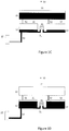
- a rotational device for handling liquid comprises an upstream liquid handling structure 21 for supplying liquid to a first 31 and second chamber 32 through a respective conduit 51, 52 in response to a centrifugal pressure when the device is rotated about an axis 10.
- the first 31 and second chambers 32 are connected by a conduit 41 having a bend that extends radially inwards to a crest and radially outwards from the crest.
- the conduit 41 connects the outlet port of the second chamber 32 to an inlet port of the first chamber 31.
- the bend of the conduit 41 enables gas to be trapped in the bend portion when the first 31 and second chambers 32 are filled, such that liquid is held in the second chamber 32 until the gas is vented through the first chamber 31, as described in detail below.
- the chamber 31 is connected to a downstream liquid handling structure 22 by a conduit 53.
- the chambers 31 and 32 each act as communicating vessels with a respective portion of the conduit 41.
- the result is, in effect, a system of communicating vessels interacting through the intermediary of gas trapped between each set of communicating vessels.
- Figure 1B illustrates an initial configuration in which the upstream liquid handling structure 21 contains a liquid 61.
- the first and second chambers 31, 32 are filled with liquid 61 flowing from the upstream liquid handling structure 21 to provide liquid volumes 62, 63 in the chambers 31, 32.
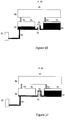
- the liquid 62 may also start to flow into the downstream liquid handling structure 22 due to the centrifugal pressure acting on it.
- the device is arranged such that as the first 31 and second chambers 32 are filled, gas 71 is trapped in the bend of the conduit 41 connecting the first 31 and second chambers 32. To this end, the respective flow rates are tuned accordingly.
- the flow rates into the first and second chambers 31, 32 depend on the centrifugally induced pressure and the hydrodynamic flow resistance.
- the centrifugally induced pressure depends on the rotational speed of the device, liquid density and radial distance of the centre of mass of the liquid column of the liquid 61.
- the hydrodynamic flow resistance of the outlet channel depends on the geometry and surface properties of the channels 51, 52 and the viscosity of the liquid 61.
- the flow rates out of the chambers 31, 32 have a similar dependence on the liquid level in these chambers and the geometry and surface properties of the channels 41 and 53. By adjusting these factors the flow rates can be controlled to allow the first 31 and second chambers 32 to fill so as to entrap gas 71 in the conduit 41 when liquids 62, 63 flow into the conduit 41 from each side.
- the capilliary force depends on the dimension, geometry and surface properties of the conduit 41 and the chambers 31, 32 where they meet the conduit 41, and tends to urge liquid into the conduit 41.
- a pressure increase due to the corresponding reduction in gas volume 71 inside the conduit 41 urges liquid in an opposite direction out of the conduit 41.
- the centrifugal pressure experienced by the liquid on either side of the bend depends on the liquid head (difference in radial height of the liquid column in the respective chambers 31, 32 and corresponding leg of the conduit 41) on either side of the bend. The centrifugal pressure tends to reduce the liquid head and therefore can force liquid into or out of the conduit 41 depending on the respective liquid levels.
- the chambers 31, 32 have continued to fill until a point in time when the levels of liquid are the same in all parts of the chambers 31, 32 and the conduit 41. This corresponds to a particular moment where pressure due to the capilliary force and the gas pressure of gas 71 balance so that the centrifugal force drives the respective liquid heads to zero on either side of the bend of conduit 41. It will be understood that this is a snapshot of the filling process and that in practice the two chambers may not fill at the same rate and not to the same level, depending on flow rates and chamber geometries.
- the level of liquids 62, 63 in the conduit 41 on either side of the bend of the conduit 41 are below the level of liquid 62, 63 in the first 31 and second chambers 32.
- the pressure of the entrapped gas 71 balances the liquid head on either side of the bend and, as a consequence, the liquid heads (the differences between the level in each chamber 31, 32 and the level in the corresponding side of the bend in the conduit 41, rather than the absolute liquid level in the chambers 31, 32) on both sides of the bend are the same.
- the liquid 63 may be held in the chamber 32 by the gas 71 entrapped in the channel 41, even if the cartridge changes its rotation speed or if it is stopped.
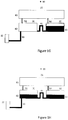
- Figure IF depicts a specific configuration in which the volume of the liquid 63 is such as to fill the conduit 41 and chamber 32 to a level corresponding to the radially inner most point of the conduit 41.
- the capilliary force tends to draw the liquid 63 into the conduit 41.
- any liquid remaining in the conduit 41 on the side adjacent the chamber 31 imposes a negative pressure on the gas 71 as it flows out of the conduit, thus drawing liquid 63 further into the conduit 41.
- the centrifugal force will act to siphon the liquid 63 into the chamber 31, as described in more detail below.
- the siphoning regime is still achievable if the conduit 41 has dimensions, geometry and surface properties designed to overcome the centrifugal pressure associated with a liquid head in the conduit 41 above the level of liquid 63 in the chamber 31 if the volume of liquid 63 is below the threshold volume.
- the capilliary force is generally small compared to centrifugal forces acting on any appreciateable liquid heads at even relatively low rotation frequencies, the siphon emptying of liquid 63 can then only be achieved up to a threshold frequency of rotation.
- liquid 63 could be pushed across the conduit 41 before the desired moment negating the sequencing action described above.
- the chamber 32 and its corresponding leg of the conduit 41 are filled with a volume greater than the threshold volume, there is a residual liquid head once the liquid 63 has advanced up to the radially innermost point of the conduit 41, which needs to be balanced by the pressure of gas 71 and hence the liquid head of liquid 62 if flow of liquid 63 into chamber 31 is to be held off. This means that under such conditions, liquid 63 can flow into the chamber 31 before the liquid head on liquid 62 is zero, i.e. before complete emptying.
- the chambers 31, 32 are now filled with the same liquid 63 without an intermediary gas volume and therefore act as communicating vessels with the liquid level in chambers 31 and 32 equalising due to the centrifugal force.
- the liquid 63 continues to empty through conduit 53, the liquid level in both chambers 31 and 32 is reduced until they are completely emptied (including the conduit 41 provided that the port to chamber 31 is at a radially outermost point of the conduit 41), as illustrated in Figure 1I .
- upstream the liquid handling structure 21 does not need to be filled with one single liquid 61 and could be composed of different chambers, reservoirs or channels.
- One example is an upstream liquid handling structure with two upstream chambers each having a specific liquid of a different nature (e.g. a buffer and a diluted blood plasma, or any other liquids), with each chamber connected separately to the sequencing structure by the channels 51 and 52, respectively.
- This arrangement results in a sequential flow pattern of the two different liquids (in the above example, the sequential flow of first a buffer and then a diluted blood plasma, or any other liquids).
- Some embodiments dispense with one of chambers 31 and 32.
- the channel 41 directly connects the chamber 31 to an upstream circuit 21, without the need for the chamber 32 and the channel 52.
- the main requirement in this case, would be that the flow rate of the liquid 62 into the chamber 31 would be sufficiently greater than the flow of the liquid 61 coming from the upstream circuit 21 into the channel 41 to cause a volume of gas 71 to be trapped in the conduit 41 as described above.
- a fraction of the channel 41 would be filled by trapped gas 71 and therefore enable the liquid sequencing of the liquid 62 that has filled the chamber 31 and the liquid 61 from the upstream circuits 21.
- control of the flow rates mentioned above may be easily obtained by designing the channels to have different cross-sections since the channel cross-section is inversely related to the hydraulic resistance.
- the flow rates may be controlled by placing the channels at different radii based on the flow rate dependence on radial position.
- the chambers described above are replaced by corresponding channels, placing them in defined positions in order to exploit the effect described above.
- the entrapped gas 71 will have a pressure higher than the pressure in chambers 31, 32 (e.g. atmospheric pressure), since the entrapped gas 71 is compressed by the displacement of the liquids 62 and 63 into the conduit 41.
- more than two liquids are sequenced.
- One example of multiple sequential flow consists in using several channels of similar nature to the channel 41, arranged either in parallel (leading to one and the same fluidic structure, either a channel or a chamber) or in series (a channel is connected to a certain fluidic structure, which in turn is connected to another channel and so on).
- a combination of serial and parallel arrangements in order to achieve a higher number of sequential flows is also envisaged.
- the upstream and downstream liquid handling structures 21, 22 may contain any type of liquid handling arrangements, namely aliquoting units, mixing units, particulate separation units, detection structures, or any type of fluidic functional structure.
- the described embodiments can be exploited to perform sequential flow without changing the rotational speed of the device. This may be advantageous in many detection applications where mechanical stability and signal acquisition stability are of critical importance.
- a cartridge 100 in the form of a disk has an axis of rotation 110, an inner contour 120 and an outer contour 130.
- the cartridge contains a variety of liquid handling structures designed to perform analytical functions when appropriately operated with a specific rotational protocol.
- the cartridge 100 includes upstream liquid handling structures not represented in Figure 2 , connected by conduits 310, 340 and 330 to, respectively, chambers 210, 230 and 220. Further, a conduit 320 also connects an upstream liquid handling structure(s) to the chamber 210.
- the liquid handling structures can include, but are not limited to aliquoting structures (e.g. delivering certain liquids to the conduits 310, 320, 330, 340), mixing structures, blood plasma separation structures, metering structures, etc. A series of different fluidic functions may be performed prior to the fluid sequencing function described herein.
- liquid starts to flow in the channels 310, 320, 330 and 340 from the upstream liquid handling structures into the chambers 210, 220 and 230 as is now described.
- a first flow path for a first liquid comprises the conduit 310 feeding into chamber 210 which has an outlet conduit 510 leading to downstream liquid handling structures.
- the downstream liquid handling structures include a detection chamber 250 fed from the outlet conduit 510 and in turn connected by a conduit 520 to a waste chamber 240.
- the embodiments described herein are not limited to this specific arrangement of the downstream liquid handling structures. Rather the described sequencing mechanism is applicable irrespective of the downstream liquid handling structures fed by the sequenced liquids, and other downstream liquid handling structures will readily be employed depending on the application at hand.
- a second liquid flow path for a second liquid includes the conduit 340 feeding into the chamber 230, which in turn is connected by a conduit 430 to the chamber 210 from where the second flow path coincides with the first flow path described above.
- the conduit 430 is configured with a radially inward bend analogous to conduit 41 discussed above to sequence liquid flow from chamber 230 to chamber 210 as described above.
- a third liquid flow path for a third liquid comprises the conduit 330 feeding into the chamber 220, which in turn is connected to the chamber 210 by a conduit 420.
- the conduit 420 is arranged analogously to the conduit 41 described above to sequence flow from the chamber 220 to the chamber 210. From the chamber 210, the third flow path coincides with the first and second flow paths through the conduit 510 and onwards downstream.
- a fourth liquid flow path for a fourth liquid includes the conduit 320 feeding into the chamber 210, from where the fourth liquid flow path coincides with the third, second and first liquid flow paths through the conduit 510 and onwards downstream.
- the conduit 320 is fed directly from upstream liquid handling structures and is arranged with a radially inward bend analogous to conduit 41 discussed above to sequence liquid from the relevant portion of the upstream liquid handling structure to the chamber 210.
- the cartridge 100 is arranged such that the inflow rates into the chamber 210 (from conduits 310, 320, 420 and 430) are larger than the outflow rate from the chamber 210 through conduit 510 by appropriate design of the geometry dimensions and/or surface properties of the conduits involved. As a result, as long as liquid flows into the chamber 210 from one of the conduits 310, 320, 420 or 430, the liquid level in the chamber 210 will rise and only fall if there is no liquid inflow into the chamber 210 but only liquid outflow through conduit 510.
- the ports from conduits 310, 320, 420 and 430 into the chamber 210 are arranged such that the port of conduit 420 is disposed radially outward of the port of conduit 430 and the port of conduit 320 is disposed radially outward of the port of conduit 420. As described below in detail, this arrangement of radial port positions determines the sequence of liquid flows. Additionally, in the specific embodiment shown in Figure 2 , the port into the chamber 210 from conduit 310 is disposed radially inward of the other ports discussed above, although this does not constrain the sequencing of liquids, and other port locations for the conduit 310 are equally possible without departing from the sequence now described.
- conduits 310, 340 and 330 fill, respectively, chambers 210, 230 and 220.
- the respective flow rates are adapted such that gas is trapped in conduits 420 and 430 as described above for conduit 41, in the bend portion of the respective conduit.
- liquid flows into channel 320 from upstream liquid handling structures at a rate so that gas is trapped in the radially inward bend of the conduit 320 between a liquid advancing from the upstream liquid handling structures and liquid advancing into the channel 320 from chamber 210 due to capilliary forces.
- liquid fills the chamber 210 from conduit 310, the chamber 230 from conduit 340, and the chamber 220 from conduit 330 while liquid is held in the conduit 320.
- liquid may start to flow from chamber 210 through conduit 510 at a rate lower than the rate of liquid flowing into the chamber 210, or the conduit 510 may be provided with a means for temporarily blocking outflow from the chamber 210.
- An example of a temporary block may be a capilliary siphon arrangement positioned in the conduit 510 which blocks liquid flow in the conduit 510 upon initial rotation by virtue of an opposed centrifugal force and allows liquid to flow subsequent to priming of the capillary siphon (liquid advancing across a crest of the siphon due to capilliary forces as the rotational frequency is slowed down sufficiently), subsequent to which liquid can flow freely in the conduit 510 due to a siphon effect, as is well known to the person skilled in the art.
- the trapped gas in conduit 430 is vented and liquid flow from chamber 230 to chamber 210 starts while liquid is held in chamber 220 and conduit 320.
- the inflow rate through conduit 430 is arranged to be at least equal to or greater than the outflow rate from chamber 210 through conduit 510, and hence the liquid level in the chamber 210 subsequently remains stable or rises again until liquid flow from chamber 230 through conduit 430 to chamber 210 ceases.
- the liquid level in the chamber 210 again starts to drop until the liquid level drops to or just below the port of conduit 420 to vent the gas trapped in conduit 420 and start liquid flow from chamber 220 through conduit 420 into chamber 210 while liquid is held in conduit 320, so that the liquid level in chamber 210 again remains stable or rises as described above for the flow from chamber 230.
- the embodiment of Figure 2 thus enables a first, second, third and fourth liquid to flow in sequence into a common sequencing chamber (chamber 210), from which they can flow onwards downstream (through conduit 510 through any appropriate downstream liquid handling structure) in sequence.
- a common sequencing chamber chamber 210
- the embodiment of Figure 2 provides for sequencing of four liquids through a common sequencing chamber by appropriate arrangements of the respective ports leading into the common sequencing chamber and configuration of the conduits feeding into the chamber in line with the principles discussed above with reference to Figure 1 .
- the above sequence of liquid flows can be achieved at constant rotational frequency (and hence constant centrifugal driving force) and does not require any particular rotational protocol.
- this can be beneficial to optical detection processes and also allows the rotational protocol to be designed as required for the liquid handling functions implemented on the cartridge 100, as a constant rotational frequency is not a requirement to achieve sequencing.
- the above embodiment clearly is not limited to any particular liquids, which could all be the same, or different or a combination thereof.
- an example in which such sequences of four liquids find application is the detection of antibodies in a sample using an optical detection technique.
- the first liquid is a reference liquid used for an initial wash of the detection structure 250 and also to obtain a baseline reading.
- the second liquid is a sample containing substances (antigens) to be identified by binding to antibodies immobilized in the detection structure 250, such that the binding can then be detected by an optical technique such as fluorescence microscopy or surface plasmon resonance.
- the third liquid is an amplifying substance to amplify the signal associated with the binding of antibodies and antigens in the detection structure to facilitate quantitative analysis of binding events.
- the fourth liquid is a wash liquid to wash away any unbound antigens and amplifier for subsequent detection of a signal for comparison with the initially obtained base line. Often, the liquid used for the final wash and initial wash/base line will be the same liquid. Of course, it will be understood that this is only a particular example of an application of a four liquid sequence and that the described embodiments are applicable to any application of liquid sequencings, be it with four, more, or less, liquids to be sequenced.
- the described embodiments enable sequential flow of liquids (e.g. four liquids in the Figure 2 embodiment) from upstream liquid handling structures into downstream liquid handling structures, without the need for any active elements, nor any need for complicated surface tension requirements or any particular rotational frequency protocols. It can thus be stressed that the sequence of liquid flows described above may all occur while the cartridge is rotated at a constant rotational frequency, without the need for repeated acceleration and deceleration, for example, if serial capilliary siphons were employed to sequence liquid flows. (Naturally, the rotational frequency could be varied during the liquid sequence but this is not necessary to obtain the desired sequence of liquid that flows described above). In many applications, there can be a significant advantage to rotate the cartridge 100 always at the same rotational frequency during the sequential flow of liquids, in particular in cartridges in which optical detection is used. In optical detection systems, the constant rotational frequency may contribute to an increased signal to noise ratio.
- chambers 210 and 220 are connected by an additional conduit 620 at a radially inward aspect to provide a vent conduit so that pressure between the two chambers can equilibrate at all times.
- chamber 210 is also connected to chamber 230 by a similar vent circuit 610.
- a further vent conduit (not shown) connects one of the chambers 210, 220 or 230 to atmospheric pressure or a closed vent circuit (a circuit enabling gas to move around the cartridge from downstream regions as it is displaced by liquid flowing upstream to downstream) to ensure efficient flow from the upstream fluidic structure through channels 310, 320, 330 and 340.
- the waste chamber 240 is connected to atmospheric pressure or a vent circuit by vent conduit 630, thus venting not only the waste chamber 240 but also conduits 510 and 520, as well as the detection structure 250 as liquid flows from the chamber 210 into the conduit 510 and on downstream. It will be appreciated that the embodiments described above are not limited to any particular way of pressure equilibration around the cartridge 100 and that many ways of maintaining appropriate pressure conditions so as not to impede liquid flows throughout the cartridge will be apparent to a person skilled in the art.
- a drive system 700 for driving a cartridge 100 comprises a controller 710 for controlling the application of a driving force to drive liquid flow in the cartridge 100 or other device.
- the system 700 comprises a motor 720 under control of the controller 710 and in one particular embodiment, the motor 720 is coupled to a spindle for engaging the inner contour 120 of the cartridge 100.
- the controller 710 is arranged to control the driving force in accordance with a predefined schedule, for example an initial rotation to distribute liquids around the cartridge 100, followed by a brief deceleration to prime a capilliary siphon in the conduit 510 followed by reacceleration and rotation at a constant rotation frequency to sequence liquids in the cartridge 100 as described above.
- a predefined schedule for example an initial rotation to distribute liquids around the cartridge 100, followed by a brief deceleration to prime a capilliary siphon in the conduit 510 followed by reacceleration and rotation at a constant rotation frequency to sequence liquids in the cartridge 100 as described above.
- microfluidic is referred to herein to mean devices having a fluidic element such as a reservoir or a channel with at least one dimension below lmm.
Landscapes
- Chemical & Material Sciences (AREA)
- Health & Medical Sciences (AREA)
- Chemical Kinetics & Catalysis (AREA)
- Dispersion Chemistry (AREA)
- Clinical Laboratory Science (AREA)
- Analytical Chemistry (AREA)
- Hematology (AREA)
- General Health & Medical Sciences (AREA)
- Physics & Mathematics (AREA)
- General Physics & Mathematics (AREA)
- Engineering & Computer Science (AREA)
- Automation & Control Theory (AREA)
- Organic Chemistry (AREA)
- Automatic Analysis And Handling Materials Therefor (AREA)
Claims (7)
- Flüssigkeitshandhabungssystem (10), umfassend:eine zentrifugale mikrofluidische Vorrichtung, umfassend:eine erste Flüssigkeitshaltestruktur (31, 210);eine zweite Flüssigkeitshaltestruktur (32, 220); undeine stromabwärtige Flüssigkeitshandhabungsstruktur (22, 250);eine Leitung (41, 420) zwischen den ersten und zweiten Flüssigkeitshaltestrukturen; undeine Leitung (53) zwischen der ersten Flüssigkeitshaltestruktur und der stromabwärtigen Flüssigkeitshandhabungsstruktur; undMittel zum Drehen der zentrifugalen mikrofluidischen Vorrichtung;dadurch gekennzeichnet, dass die Leitung (41, 420) eine Krümmung umfasst, die sich radial einwärts zu einem Scheitelpunkt und radial auswärts vom Scheitelpunkt erstreckt, wobei das Flüssigkeitshandhabungssystem das Folgende umfasst:Mittel zum Füllen der ersten (31, 210) und der zweiten (32, 220) Flüssigkeitshaltestruktur mit Flüssigkeit zum Einschließen von Gas (71) in der Krümmung der Leitung (41, 420) zwischen den ersten und zweiten Flüssigkeitshaltestrukturen;Mittel zum Bewegen von Flüssigkeit von der ersten Flüssigkeitshaltestruktur (31, 210) zur stromabwärtigen Flüssigkeitshandhabungsstruktur (22, 250), während Flüssigkeit von dem in der Leitung eingeschlossenen Gas in der zweiten Flüssigkeitshaltestruktur (32, 220) zurückgehalten wird; undMittel zum Bewegen von Flüssigkeit von der zweiten Flüssigkeitshaltestruktur (32, 220) durch die Leitung (41, 420) und die erste Flüssigkeitshaltestruktur (31, 210) zur stromabwärtigen Flüssigkeitshandhabungsstruktur (22, 250) im Anschluss an die Entlüftung des eingeschlossenen Gases (71) aus der Leitung (41, 420) durch die erste Flüssigkeitshaltestruktur.
- Flüssigkeitshandhabungssystem nach Anspruch 1, ferner umfassend:Mittel zum Füllen einer dritten Flüssigkeitshaltestruktur (230) mit Flüssigkeit zum Einschließen von Gas in einer weiteren Leitung (430) zwischen den ersten (210) und dritten (230) Flüssigkeitshaltestrukturen;Mittel zum Bewegen von Flüssigkeit von der ersten (210) und zweiten (220) Flüssigkeitshaltestruktur zur stromabwärtigen Flüssigkeitshandhabungsstruktur, während Flüssigkeit in der dritten Flüssigkeitshaltestruktur (230) zurückgehalten wird; undMittel zum Bewegen von Flüssigkeit von der dritten Flüssigkeitshaltestruktur (230) durch die weitere Leitung (430) und die erste Flüssigkeitshaltestruktur (210) zur stromabwärtigen Flüssigkeitshandhabungsstruktur (250) im Anschluss an die Entlüftung des eingeschlossenen Gases aus der weiteren Leitung (430) durch die erste Flüssigkeitshaltestruktur (210).
- Flüssigkeitshandhabungssystem nach Anspruch 1 oder 2, umfassend Mittel zum Bewegen von Flüssigkeit von den ersten und zweiten Flüssigkeitshaltestrukturen als Reaktion auf eine im Wesentlichen konstante Antriebskraft.
- Flüssigkeitshandhabungssystem nach einem der vorhergehenden Ansprüche, umfassend einen Motor zum Drehen der zentrifugalen mikrofluidischen Vorrichtung.
- Verfahren zum sequentiellen Bewegen von Flüssigkeit unter Verwendung eines Flüssigkeitshandhabungssystems nach einem der Ansprüche 1 bis 4 von den ersten (31, 210) und den zweiten (32, 220) Flüssigkeitshaltestrukturen der zentrifugalen mikrofluidischen Vorrichtung zur stromabwärtigen Flüssigkeitshandhabungsstruktur (22, 250) der zentrifugalen mikrofluidischen Vorrichtung, wobei das Verfahren dadurch gekennzeichnet ist, dass die zentrifugale mikrofluidische Vorrichtung unter Verwendung des Drehmittels gedreht wird, um:die ersten (31, 210) und zweiten (32, 220) Flüssigkeitshaltestrukturen zum Einschließen von Gas (71) in der Leitung (41, 420) zwischen den ersten und zweiten Flüssigkeitshaltestrukturen mit Flüssigkeit zu füllen;Flüssigkeit von der ersten Flüssigkeitshaltestruktur (31, 210) zur stromabwärtigen Flüssigkeitshandhabungsstruktur (22, 250) zu bewegen, während Flüssigkeit in der zweiten Flüssigkeitshaltestruktur (32, 220) zurückgehalten wird; undFlüssigkeit von der zweiten Flüssigkeitshaltestruktur (32, 220) durch die Leitung (41, 420) und die erste Flüssigkeitshaltestruktur (31, 210) zur stromabwärtigen Flüssigkeitshandhabungsstruktur (22, 250) nach Entlüftung des eingeschlossenen Gases (71) aus der Leitung (41, 420) durch die erste Flüssigkeitshaltestruktur zu bewegen.
- Verfahren nach Anspruch 5, wobei das Verfahren ferner das Drehen der Vorrichtung umfasst, um:eine dritte (230) Flüssigkeitshaltestruktur zum Einschließen von Gas in einer weiteren Leitung (430) zwischen den ersten (210) und dritten (230) Flüssigkeitshaltestrukturen mit Flüssigkeit zu füllen;Flüssigkeit von der ersten (210) und zweiten (220) Flüssigkeitshaltestruktur zur stromabwärtigen Flüssigkeitshandhabungsstruktur zu bewegen, während Flüssigkeit in der dritten Flüssigkeitshaltestruktur (230) zurückgehalten wird; undFlüssigkeit von der dritten Flüssigkeitshaltestruktur (230) durch die weitere Leitung (430) und die erste Flüssigkeitshaltestruktur (210) zur stromabwärtigen Flüssigkeitshandhabungsstruktur (250) nach Entlüftung des eingeschlossenen Gases aus der weiteren Leitung (430) durch die erste Flüssigkeitshaltestruktur (210) zu bewegen.
- Verfahren nach den Ansprüchen 5 oder 6, wobei die Drehung der Vorrichtung die Drehung der Vorrichtung mit einer im Wesentlichen konstanten Geschwindigkeit umfasst.
Applications Claiming Priority (2)
| Application Number | Priority Date | Filing Date | Title |
|---|---|---|---|
| PT10558311 | 2011-03-24 | ||
| EP12716626.2A EP2688674B1 (de) | 2011-03-24 | 2012-03-23 | Steuerung von den flussreihenfolge von flüssigkeit auf einer mikrofluidischen-vorrichtung |
Related Parent Applications (1)
| Application Number | Title | Priority Date | Filing Date |
|---|---|---|---|
| EP12716626.2A Division EP2688674B1 (de) | 2011-03-24 | 2012-03-23 | Steuerung von den flussreihenfolge von flüssigkeit auf einer mikrofluidischen-vorrichtung |
Publications (3)
| Publication Number | Publication Date |
|---|---|
| EP3000530A2 EP3000530A2 (de) | 2016-03-30 |
| EP3000530A3 EP3000530A3 (de) | 2016-05-11 |
| EP3000530B1 true EP3000530B1 (de) | 2018-05-23 |
Family
ID=45999908
Family Applications (2)
| Application Number | Title | Priority Date | Filing Date |
|---|---|---|---|
| EP15192652.4A Not-in-force EP3000530B1 (de) | 2011-03-24 | 2012-03-23 | Regelung der flüssigkeitsströmungssequenz auf einer mikrofluidischen vorrichtung |
| EP12716626.2A Not-in-force EP2688674B1 (de) | 2011-03-24 | 2012-03-23 | Steuerung von den flussreihenfolge von flüssigkeit auf einer mikrofluidischen-vorrichtung |
Family Applications After (1)
| Application Number | Title | Priority Date | Filing Date |
|---|---|---|---|
| EP12716626.2A Not-in-force EP2688674B1 (de) | 2011-03-24 | 2012-03-23 | Steuerung von den flussreihenfolge von flüssigkeit auf einer mikrofluidischen-vorrichtung |
Country Status (7)
| Country | Link |
|---|---|
| US (2) | US9625916B2 (de) |
| EP (2) | EP3000530B1 (de) |
| JP (1) | JP6116543B2 (de) |
| KR (1) | KR101956265B1 (de) |
| CN (1) | CN103517762B (de) |
| BR (1) | BR112013024496A2 (de) |
| WO (1) | WO2012131556A1 (de) |
Cited By (1)
| Publication number | Priority date | Publication date | Assignee | Title |
|---|---|---|---|---|
| US12090479B2 (en) | 2019-04-18 | 2024-09-17 | Lg Chem, Ltd. | Method for detecting aldehydes or ketones |
Families Citing this family (27)
| Publication number | Priority date | Publication date | Assignee | Title |
|---|---|---|---|---|
| GB2464721C (en) * | 2008-10-23 | 2013-08-14 | Biosurfit Sa | Jet deflection device |
| GB2476474B (en) | 2009-12-22 | 2012-03-28 | Biosurfit Sa | Surface plasmon resonance detection system |
| GB2479139A (en) | 2010-03-29 | 2011-10-05 | Biosurfit Sa | A liquid distribution and metering device |
| EP2595754B1 (de) | 2010-07-22 | 2018-04-04 | Gencell Biosystems Limited | Verbund-flüssigkeitszellen |
| EP3000530B1 (de) | 2011-03-24 | 2018-05-23 | Biosurfit, S.A. | Regelung der flüssigkeitsströmungssequenz auf einer mikrofluidischen vorrichtung |
| DE102012202775B4 (de) * | 2012-02-23 | 2016-08-25 | Hahn-Schickard-Gesellschaft für angewandte Forschung e.V. | Fluidikmodul, vorrichtung und verfahren zum pumpen einer flüssigkeit |
| CA2888042A1 (en) | 2012-11-27 | 2014-06-05 | Gencell Biosystems Ltd. | Handling liquid samples |
| US11219896B2 (en) * | 2013-06-25 | 2022-01-11 | University Of Washington Through Its Center For Commercialization | Self-digitization of sample volumes |
| CN106029885A (zh) * | 2014-02-10 | 2016-10-12 | 基因细胞生物系统有限公司 | 复合液体池(clc)介导的核酸文库制备装置及其使用方法 |
| EP3142796A4 (de) | 2014-05-16 | 2017-12-20 | Qvella Corporation | Vorrichtung, system und verfahren zur durchführung einer automatischen zentrifugaltrennung |
| DE102014211121A1 (de) * | 2014-06-11 | 2015-12-17 | Hahn-Schickard-Gesellschaft für angewandte Forschung e.V. | Fluidikmodul, vorrichtung und verfahren zum handhaben von flüssigkeit |
| EP3204752B1 (de) | 2014-10-06 | 2019-07-24 | Biosurfit, S.A. | Bindungstestanalyse |
| CN113791202B (zh) * | 2015-06-12 | 2024-07-12 | 芯易诊有限公司 | 用于分析流体样品的流体设备及用于分析生物样品的方法 |
| WO2017103029A1 (en) * | 2015-12-16 | 2017-06-22 | Biosurfit, S.A. | A device and method for handling liquid |
| WO2017165630A1 (en) | 2016-03-23 | 2017-09-28 | Truvian Sciences, Inc. | Systems and methods for multianalyte detection |
| PL3464916T3 (pl) * | 2016-05-26 | 2022-02-21 | Flender-Graffenstaden S.A.S. | Łożysko hydrodynamiczne z wtryskiwaczami i deflektorami |
| WO2017212031A1 (en) * | 2016-06-09 | 2017-12-14 | Biosurfit, S.A. | Liquid handling device for rotationally driving liquid flow and method of using device |
| US10639635B2 (en) * | 2016-10-07 | 2020-05-05 | Biosurfit, SA | Device and method for handling liquid |
| US20200230600A1 (en) | 2017-07-27 | 2020-07-23 | Biosurfit, S.A. | Apparatus and methods for handling liquid |
| WO2019136134A2 (en) * | 2018-01-05 | 2019-07-11 | Genturi, Inc. | Duty cycle optimization in single-molecule detection |
| KR102301178B1 (ko) | 2018-06-25 | 2021-09-09 | 주식회사 엘지화학 | 알데히드류 또는 케톤류 검출용 마이크로 디바이스 |
| KR102318501B1 (ko) | 2018-08-21 | 2021-10-28 | 주식회사 엘지화학 | 마이크로 디바이스를 이용한 고상 추출 방법 |
| KR102463382B1 (ko) | 2019-04-19 | 2022-11-03 | 주식회사 엘지화학 | 알데히드류 또는 케톤류 검출용 마이크로 디바이스 |
| DE102021208891B3 (de) * | 2021-08-13 | 2022-10-13 | Hahn-Schickard-Gesellschaft für angewandte Forschung e.V. | Unterdruckschalten von Flüssigkeit |
| CN115074230B (zh) * | 2022-07-21 | 2023-05-23 | 北京泰豪生物科技有限公司 | 试剂控释模块、生物反应器以及生物检测装置 |
| USD1116151S1 (en) | 2023-05-03 | 2026-03-03 | Truvian Sciences, Inc. | Monolayer |
| DE102023207560B3 (de) | 2023-08-07 | 2024-05-08 | Hahn-Schickard-Gesellschaft für angewandte Forschung e.V. | Halten und Transferieren von Flüssigkeiten |
Citations (1)
| Publication number | Priority date | Publication date | Assignee | Title |
|---|---|---|---|---|
| CN101906378A (zh) * | 2010-07-05 | 2010-12-08 | 博奥生物有限公司 | 一种气泡微阀及基于此气泡微阀的微流控芯片 |
Family Cites Families (18)
| Publication number | Priority date | Publication date | Assignee | Title |
|---|---|---|---|---|
| AU8083891A (en) * | 1990-06-04 | 1991-12-31 | Abaxis, Inc. | Analytical rotors and methods for analysis of biological fluids |
| US6709869B2 (en) | 1995-12-18 | 2004-03-23 | Tecan Trading Ag | Devices and methods for using centripetal acceleration to drive fluid movement in a microfluidics system |
| EP0983504A2 (de) * | 1997-05-23 | 2000-03-08 | Gamera Bioscience Corporation | Verfahren und vorrichtungen zur benutzung der zentripetalbeschleunigung für die bewegung von flüssigkeiten in einem mikrofluidiksystem |
| DE10302721A1 (de) * | 2003-01-23 | 2004-08-05 | Steag Microparts Gmbh | Mikrofluidische Anordnung zum Dosieren von Flüssigkeiten |
| JP2007500351A (ja) | 2003-07-25 | 2007-01-11 | 長岡実業株式会社 | バイオディスクを有するサンプル調製用流体回路及びそれに関連した方法 |
| EP1827668A1 (de) * | 2004-12-08 | 2007-09-05 | Danfoss A/S | Blasentolerante mikromischer |
| US7449051B2 (en) * | 2005-07-11 | 2008-11-11 | Hewlett-Packard Development Company, L.P. | Separation of liquid and gas from froth |
| US20090169430A1 (en) * | 2006-04-04 | 2009-07-02 | Matsushita Electric Industrial Co., Ltd. | Panel for analyzing sample liquid |
| EP2135069A4 (de) | 2007-03-02 | 2011-03-09 | Univ Laval | In reihe geschaltete heberventile für fluidik- oder mikrofluidik-vorrichtungen |
| JP5376429B2 (ja) | 2007-10-30 | 2013-12-25 | パナソニック株式会社 | 分析用デバイスとこれを使用する分析装置および分析方法 |
| GB2464721C (en) | 2008-10-23 | 2013-08-14 | Biosurfit Sa | Jet deflection device |
| GB2466644B (en) | 2008-12-30 | 2011-05-11 | Biosurfit Sa | Liquid handling |
| WO2010084190A1 (en) | 2009-01-23 | 2010-07-29 | Dublin City University | Fluidic single use valve and microfluidic systems incorporating said valve |
| KR20110009022A (ko) * | 2009-07-20 | 2011-01-27 | 삼성전자주식회사 | 디스크형 미세유동장치 및 이를 이용하는 혈액검사장치 |
| GB2479139A (en) | 2010-03-29 | 2011-10-05 | Biosurfit Sa | A liquid distribution and metering device |
| EP3000530B1 (de) | 2011-03-24 | 2018-05-23 | Biosurfit, S.A. | Regelung der flüssigkeitsströmungssequenz auf einer mikrofluidischen vorrichtung |
| WO2012131598A1 (en) | 2011-03-28 | 2012-10-04 | Biosurfit, S.A. | Liquid switching, dosing and pumping |
| WO2012137122A1 (en) | 2011-04-02 | 2012-10-11 | Biosurfit, S.A. | Liquid reagent storage and operation of analytical devices |
-
2012
- 2012-03-23 EP EP15192652.4A patent/EP3000530B1/de not_active Not-in-force
- 2012-03-23 BR BR112013024496A patent/BR112013024496A2/pt not_active Application Discontinuation
- 2012-03-23 EP EP12716626.2A patent/EP2688674B1/de not_active Not-in-force
- 2012-03-23 JP JP2014500531A patent/JP6116543B2/ja active Active
- 2012-03-23 CN CN201280021051.1A patent/CN103517762B/zh not_active Expired - Fee Related
- 2012-03-23 KR KR1020137027484A patent/KR101956265B1/ko active Active
- 2012-03-23 WO PCT/IB2012/051411 patent/WO2012131556A1/en not_active Ceased
- 2012-03-23 US US14/007,257 patent/US9625916B2/en active Active
-
2017
- 2017-02-10 US US15/429,432 patent/US9908116B2/en active Active
Patent Citations (2)
| Publication number | Priority date | Publication date | Assignee | Title |
|---|---|---|---|---|
| CN101906378A (zh) * | 2010-07-05 | 2010-12-08 | 博奥生物有限公司 | 一种气泡微阀及基于此气泡微阀的微流控芯片 |
| US20130206250A1 (en) * | 2010-07-05 | 2013-08-15 | Tsinghua University | Bubble-based microvalve and its use in microfluidic chip |
Cited By (1)
| Publication number | Priority date | Publication date | Assignee | Title |
|---|---|---|---|---|
| US12090479B2 (en) | 2019-04-18 | 2024-09-17 | Lg Chem, Ltd. | Method for detecting aldehydes or ketones |
Also Published As
| Publication number | Publication date |
|---|---|
| CN103517762A (zh) | 2014-01-15 |
| US9625916B2 (en) | 2017-04-18 |
| KR20140035893A (ko) | 2014-03-24 |
| WO2012131556A1 (en) | 2012-10-04 |
| CN103517762B (zh) | 2015-12-23 |
| BR112013024496A2 (pt) | 2016-12-27 |
| EP2688674A1 (de) | 2014-01-29 |
| EP2688674B1 (de) | 2015-11-04 |
| KR101956265B1 (ko) | 2019-06-24 |
| EP3000530A2 (de) | 2016-03-30 |
| EP3000530A3 (de) | 2016-05-11 |
| US20170151559A1 (en) | 2017-06-01 |
| US20140109972A1 (en) | 2014-04-24 |
| JP6116543B2 (ja) | 2017-04-19 |
| JP2014508952A (ja) | 2014-04-10 |
| US9908116B2 (en) | 2018-03-06 |
Similar Documents
| Publication | Publication Date | Title |
|---|---|---|
| US9908116B2 (en) | Control of liquid flow sequence on microfluidic device | |
| EP3389866B1 (de) | Vorrichtung und verfahren zur handhabung einer flüssigkeit | |
| EP2552589B1 (de) | Flüssigkeitsverteilung und messung | |
| EP3468716B1 (de) | Flüssigkeitshandhabungsvorrichtung zur rotationsansteuerung eines flüssigkeitsstroms | |
| US11141728B2 (en) | Centrifugo-pneumatic switching of liquid | |
| US20140134631A1 (en) | Centrifugal microfluidic platform | |
| US10232105B2 (en) | Multi-chamber microfluidic device | |
| US11964274B2 (en) | Device and method for handling liquid |
Legal Events
| Date | Code | Title | Description |
|---|---|---|---|
| PUAI | Public reference made under article 153(3) epc to a published international application that has entered the european phase |
Free format text: ORIGINAL CODE: 0009012 |
|
| AC | Divisional application: reference to earlier application |
Ref document number: 2688674 Country of ref document: EP Kind code of ref document: P |
|
| AK | Designated contracting states |
Kind code of ref document: A2 Designated state(s): AL AT BE BG CH CY CZ DE DK EE ES FI FR GB GR HR HU IE IS IT LI LT LU LV MC MK MT NL NO PL PT RO RS SE SI SK SM TR |
|
| PUAL | Search report despatched |
Free format text: ORIGINAL CODE: 0009013 |
|
| 111Z | Information provided on other rights and legal means of execution |
Free format text: AL AT BE BG CH CY CZ DE DK EE ES FI FR GB GR HR HU IE IS IT LT LU LV MC MK MT NL NO PL PT RO RS SE SI SK SM TR Effective date: 20160330 |
|
| AK | Designated contracting states |
Kind code of ref document: A3 Designated state(s): AL AT BE BG CH CY CZ DE DK EE ES FI FR GB GR HR HU IE IS IT LI LT LU LV MC MK MT NL NO PL PT RO RS SE SI SK SM TR |
|
| RIC1 | Information provided on ipc code assigned before grant |
Ipc: G05D 7/06 20060101ALN20160406BHEP Ipc: B01L 3/00 20060101AFI20160406BHEP |
|
| STAA | Information on the status of an ep patent application or granted ep patent |
Free format text: STATUS: REQUEST FOR EXAMINATION WAS MADE |
|
| 17P | Request for examination filed |
Effective date: 20161111 |
|
| RBV | Designated contracting states (corrected) |
Designated state(s): AL AT BE BG CH CY CZ DE DK EE ES FI FR GB GR HR HU IE IS IT LI LT LU LV MC MK MT NL NO PL PT RO RS SE SI SK SM TR |
|
| STAA | Information on the status of an ep patent application or granted ep patent |
Free format text: STATUS: EXAMINATION IS IN PROGRESS |
|
| 17Q | First examination report despatched |
Effective date: 20170810 |
|
| RAP1 | Party data changed (applicant data changed or rights of an application transferred) |
Owner name: BIOSURFIT, S.A. |
|
| GRAP | Despatch of communication of intention to grant a patent |
Free format text: ORIGINAL CODE: EPIDOSNIGR1 |
|
| STAA | Information on the status of an ep patent application or granted ep patent |
Free format text: STATUS: GRANT OF PATENT IS INTENDED |
|
| INTG | Intention to grant announced |
Effective date: 20180309 |
|
| GRAS | Grant fee paid |
Free format text: ORIGINAL CODE: EPIDOSNIGR3 |
|
| GRAA | (expected) grant |
Free format text: ORIGINAL CODE: 0009210 |
|
| STAA | Information on the status of an ep patent application or granted ep patent |
Free format text: STATUS: THE PATENT HAS BEEN GRANTED |
|
| AC | Divisional application: reference to earlier application |
Ref document number: 2688674 Country of ref document: EP Kind code of ref document: P |
|
| AK | Designated contracting states |
Kind code of ref document: B1 Designated state(s): AL AT BE BG CH CY CZ DE DK EE ES FI FR GB GR HR HU IE IS IT LI LT LU LV MC MK MT NL NO PL PT RO RS SE SI SK SM TR |
|
| REG | Reference to a national code |
Ref country code: GB Ref legal event code: FG4D |
|
| REG | Reference to a national code |
Ref country code: CH Ref legal event code: EP |
|
| REG | Reference to a national code |
Ref country code: IE Ref legal event code: FG4D |
|
| REG | Reference to a national code |
Ref country code: AT Ref legal event code: REF Ref document number: 1001097 Country of ref document: AT Kind code of ref document: T Effective date: 20180615 |
|
| REG | Reference to a national code |
Ref country code: DE Ref legal event code: R096 Ref document number: 602012046767 Country of ref document: DE |
|
| REG | Reference to a national code |
Ref country code: NL Ref legal event code: MP Effective date: 20180523 |
|
| REG | Reference to a national code |
Ref country code: LT Ref legal event code: MG4D |
|
| PG25 | Lapsed in a contracting state [announced via postgrant information from national office to epo] |
Ref country code: LT Free format text: LAPSE BECAUSE OF FAILURE TO SUBMIT A TRANSLATION OF THE DESCRIPTION OR TO PAY THE FEE WITHIN THE PRESCRIBED TIME-LIMIT Effective date: 20180523 Ref country code: ES Free format text: LAPSE BECAUSE OF FAILURE TO SUBMIT A TRANSLATION OF THE DESCRIPTION OR TO PAY THE FEE WITHIN THE PRESCRIBED TIME-LIMIT Effective date: 20180523 Ref country code: BG Free format text: LAPSE BECAUSE OF FAILURE TO SUBMIT A TRANSLATION OF THE DESCRIPTION OR TO PAY THE FEE WITHIN THE PRESCRIBED TIME-LIMIT Effective date: 20180823 Ref country code: FI Free format text: LAPSE BECAUSE OF FAILURE TO SUBMIT A TRANSLATION OF THE DESCRIPTION OR TO PAY THE FEE WITHIN THE PRESCRIBED TIME-LIMIT Effective date: 20180523 Ref country code: SE Free format text: LAPSE BECAUSE OF FAILURE TO SUBMIT A TRANSLATION OF THE DESCRIPTION OR TO PAY THE FEE WITHIN THE PRESCRIBED TIME-LIMIT Effective date: 20180523 Ref country code: NO Free format text: LAPSE BECAUSE OF FAILURE TO SUBMIT A TRANSLATION OF THE DESCRIPTION OR TO PAY THE FEE WITHIN THE PRESCRIBED TIME-LIMIT Effective date: 20180823 |
|
| PG25 | Lapsed in a contracting state [announced via postgrant information from national office to epo] |
Ref country code: GR Free format text: LAPSE BECAUSE OF FAILURE TO SUBMIT A TRANSLATION OF THE DESCRIPTION OR TO PAY THE FEE WITHIN THE PRESCRIBED TIME-LIMIT Effective date: 20180824 Ref country code: LV Free format text: LAPSE BECAUSE OF FAILURE TO SUBMIT A TRANSLATION OF THE DESCRIPTION OR TO PAY THE FEE WITHIN THE PRESCRIBED TIME-LIMIT Effective date: 20180523 Ref country code: HR Free format text: LAPSE BECAUSE OF FAILURE TO SUBMIT A TRANSLATION OF THE DESCRIPTION OR TO PAY THE FEE WITHIN THE PRESCRIBED TIME-LIMIT Effective date: 20180523 Ref country code: RS Free format text: LAPSE BECAUSE OF FAILURE TO SUBMIT A TRANSLATION OF THE DESCRIPTION OR TO PAY THE FEE WITHIN THE PRESCRIBED TIME-LIMIT Effective date: 20180523 Ref country code: NL Free format text: LAPSE BECAUSE OF FAILURE TO SUBMIT A TRANSLATION OF THE DESCRIPTION OR TO PAY THE FEE WITHIN THE PRESCRIBED TIME-LIMIT Effective date: 20180523 |
|
| REG | Reference to a national code |
Ref country code: AT Ref legal event code: MK05 Ref document number: 1001097 Country of ref document: AT Kind code of ref document: T Effective date: 20180523 |
|
| PG25 | Lapsed in a contracting state [announced via postgrant information from national office to epo] |
Ref country code: PL Free format text: LAPSE BECAUSE OF FAILURE TO SUBMIT A TRANSLATION OF THE DESCRIPTION OR TO PAY THE FEE WITHIN THE PRESCRIBED TIME-LIMIT Effective date: 20180523 Ref country code: SK Free format text: LAPSE BECAUSE OF FAILURE TO SUBMIT A TRANSLATION OF THE DESCRIPTION OR TO PAY THE FEE WITHIN THE PRESCRIBED TIME-LIMIT Effective date: 20180523 Ref country code: CZ Free format text: LAPSE BECAUSE OF FAILURE TO SUBMIT A TRANSLATION OF THE DESCRIPTION OR TO PAY THE FEE WITHIN THE PRESCRIBED TIME-LIMIT Effective date: 20180523 Ref country code: RO Free format text: LAPSE BECAUSE OF FAILURE TO SUBMIT A TRANSLATION OF THE DESCRIPTION OR TO PAY THE FEE WITHIN THE PRESCRIBED TIME-LIMIT Effective date: 20180523 Ref country code: EE Free format text: LAPSE BECAUSE OF FAILURE TO SUBMIT A TRANSLATION OF THE DESCRIPTION OR TO PAY THE FEE WITHIN THE PRESCRIBED TIME-LIMIT Effective date: 20180523 Ref country code: AT Free format text: LAPSE BECAUSE OF FAILURE TO SUBMIT A TRANSLATION OF THE DESCRIPTION OR TO PAY THE FEE WITHIN THE PRESCRIBED TIME-LIMIT Effective date: 20180523 Ref country code: DK Free format text: LAPSE BECAUSE OF FAILURE TO SUBMIT A TRANSLATION OF THE DESCRIPTION OR TO PAY THE FEE WITHIN THE PRESCRIBED TIME-LIMIT Effective date: 20180523 |
|
| REG | Reference to a national code |
Ref country code: DE Ref legal event code: R097 Ref document number: 602012046767 Country of ref document: DE |
|
| REG | Reference to a national code |
Ref country code: GB Ref legal event code: 732E Free format text: REGISTERED BETWEEN 20190131 AND 20190206 |
|
| PG25 | Lapsed in a contracting state [announced via postgrant information from national office to epo] |
Ref country code: SM Free format text: LAPSE BECAUSE OF FAILURE TO SUBMIT A TRANSLATION OF THE DESCRIPTION OR TO PAY THE FEE WITHIN THE PRESCRIBED TIME-LIMIT Effective date: 20180523 Ref country code: IT Free format text: LAPSE BECAUSE OF FAILURE TO SUBMIT A TRANSLATION OF THE DESCRIPTION OR TO PAY THE FEE WITHIN THE PRESCRIBED TIME-LIMIT Effective date: 20180523 |
|
| PLBE | No opposition filed within time limit |
Free format text: ORIGINAL CODE: 0009261 |
|
| STAA | Information on the status of an ep patent application or granted ep patent |
Free format text: STATUS: NO OPPOSITION FILED WITHIN TIME LIMIT |
|
| 26N | No opposition filed |
Effective date: 20190226 |
|
| PG25 | Lapsed in a contracting state [announced via postgrant information from national office to epo] |
Ref country code: SI Free format text: LAPSE BECAUSE OF FAILURE TO SUBMIT A TRANSLATION OF THE DESCRIPTION OR TO PAY THE FEE WITHIN THE PRESCRIBED TIME-LIMIT Effective date: 20180523 |
|
| PG25 | Lapsed in a contracting state [announced via postgrant information from national office to epo] |
Ref country code: MC Free format text: LAPSE BECAUSE OF FAILURE TO SUBMIT A TRANSLATION OF THE DESCRIPTION OR TO PAY THE FEE WITHIN THE PRESCRIBED TIME-LIMIT Effective date: 20180523 |
|
| PG25 | Lapsed in a contracting state [announced via postgrant information from national office to epo] |
Ref country code: LU Free format text: LAPSE BECAUSE OF NON-PAYMENT OF DUE FEES Effective date: 20190323 Ref country code: AL Free format text: LAPSE BECAUSE OF FAILURE TO SUBMIT A TRANSLATION OF THE DESCRIPTION OR TO PAY THE FEE WITHIN THE PRESCRIBED TIME-LIMIT Effective date: 20180523 |
|
| REG | Reference to a national code |
Ref country code: BE Ref legal event code: MM Effective date: 20190331 |
|
| PG25 | Lapsed in a contracting state [announced via postgrant information from national office to epo] |
Ref country code: IE Free format text: LAPSE BECAUSE OF NON-PAYMENT OF DUE FEES Effective date: 20190323 |
|
| PG25 | Lapsed in a contracting state [announced via postgrant information from national office to epo] |
Ref country code: BE Free format text: LAPSE BECAUSE OF NON-PAYMENT OF DUE FEES Effective date: 20190331 |
|
| PG25 | Lapsed in a contracting state [announced via postgrant information from national office to epo] |
Ref country code: TR Free format text: LAPSE BECAUSE OF FAILURE TO SUBMIT A TRANSLATION OF THE DESCRIPTION OR TO PAY THE FEE WITHIN THE PRESCRIBED TIME-LIMIT Effective date: 20180523 |
|
| PGFP | Annual fee paid to national office [announced via postgrant information from national office to epo] |
Ref country code: DE Payment date: 20200327 Year of fee payment: 9 Ref country code: GB Payment date: 20200327 Year of fee payment: 9 |
|
| PG25 | Lapsed in a contracting state [announced via postgrant information from national office to epo] |
Ref country code: MT Free format text: LAPSE BECAUSE OF NON-PAYMENT OF DUE FEES Effective date: 20190323 Ref country code: PT Free format text: LAPSE BECAUSE OF FAILURE TO SUBMIT A TRANSLATION OF THE DESCRIPTION OR TO PAY THE FEE WITHIN THE PRESCRIBED TIME-LIMIT Effective date: 20180924 |
|
| PGFP | Annual fee paid to national office [announced via postgrant information from national office to epo] |
Ref country code: FR Payment date: 20200325 Year of fee payment: 9 |
|
| PGFP | Annual fee paid to national office [announced via postgrant information from national office to epo] |
Ref country code: CH Payment date: 20200401 Year of fee payment: 9 |
|
| PG25 | Lapsed in a contracting state [announced via postgrant information from national office to epo] |
Ref country code: CY Free format text: LAPSE BECAUSE OF FAILURE TO SUBMIT A TRANSLATION OF THE DESCRIPTION OR TO PAY THE FEE WITHIN THE PRESCRIBED TIME-LIMIT Effective date: 20180523 |
|
| PG25 | Lapsed in a contracting state [announced via postgrant information from national office to epo] |
Ref country code: IS Free format text: LAPSE BECAUSE OF FAILURE TO SUBMIT A TRANSLATION OF THE DESCRIPTION OR TO PAY THE FEE WITHIN THE PRESCRIBED TIME-LIMIT Effective date: 20180923 |
|
| PG25 | Lapsed in a contracting state [announced via postgrant information from national office to epo] |
Ref country code: HU Free format text: LAPSE BECAUSE OF FAILURE TO SUBMIT A TRANSLATION OF THE DESCRIPTION OR TO PAY THE FEE WITHIN THE PRESCRIBED TIME-LIMIT; INVALID AB INITIO Effective date: 20120323 |
|
| REG | Reference to a national code |
Ref country code: DE Ref legal event code: R119 Ref document number: 602012046767 Country of ref document: DE |
|
| REG | Reference to a national code |
Ref country code: CH Ref legal event code: PL |
|
| GBPC | Gb: european patent ceased through non-payment of renewal fee |
Effective date: 20210323 |
|
| PG25 | Lapsed in a contracting state [announced via postgrant information from national office to epo] |
Ref country code: FR Free format text: LAPSE BECAUSE OF NON-PAYMENT OF DUE FEES Effective date: 20210331 Ref country code: GB Free format text: LAPSE BECAUSE OF NON-PAYMENT OF DUE FEES Effective date: 20210323 Ref country code: DE Free format text: LAPSE BECAUSE OF NON-PAYMENT OF DUE FEES Effective date: 20211001 Ref country code: LI Free format text: LAPSE BECAUSE OF NON-PAYMENT OF DUE FEES Effective date: 20210331 Ref country code: CH Free format text: LAPSE BECAUSE OF NON-PAYMENT OF DUE FEES Effective date: 20210331 |
|
| PG25 | Lapsed in a contracting state [announced via postgrant information from national office to epo] |
Ref country code: MK Free format text: LAPSE BECAUSE OF FAILURE TO SUBMIT A TRANSLATION OF THE DESCRIPTION OR TO PAY THE FEE WITHIN THE PRESCRIBED TIME-LIMIT Effective date: 20180523 |