EP3000509A1 - Manufacturing method for an outer layer for a panel of a ball - Google Patents
Manufacturing method for an outer layer for a panel of a ball Download PDFInfo
- Publication number
- EP3000509A1 EP3000509A1 EP15186381.8A EP15186381A EP3000509A1 EP 3000509 A1 EP3000509 A1 EP 3000509A1 EP 15186381 A EP15186381 A EP 15186381A EP 3000509 A1 EP3000509 A1 EP 3000509A1
- Authority
- EP
- European Patent Office
- Prior art keywords
- textures
- panel
- ball
- sheet
- outer layer
- Prior art date
- Legal status (The legal status is an assumption and is not a legal conclusion. Google has not performed a legal analysis and makes no representation as to the accuracy of the status listed.)
- Granted
Links
Images




Classifications
-
- B—PERFORMING OPERATIONS; TRANSPORTING
- B29—WORKING OF PLASTICS; WORKING OF SUBSTANCES IN A PLASTIC STATE IN GENERAL
- B29C—SHAPING OR JOINING OF PLASTICS; SHAPING OF MATERIAL IN A PLASTIC STATE, NOT OTHERWISE PROVIDED FOR; AFTER-TREATMENT OF THE SHAPED PRODUCTS, e.g. REPAIRING
- B29C51/00—Shaping by thermoforming, i.e. shaping sheets or sheet like preforms after heating, e.g. shaping sheets in matched moulds or by deep-drawing; Apparatus therefor
- B29C51/08—Deep drawing or matched-mould forming, i.e. using mechanical means only
- B29C51/082—Deep drawing or matched-mould forming, i.e. using mechanical means only by shaping between complementary mould parts
-
- A—HUMAN NECESSITIES
- A63—SPORTS; GAMES; AMUSEMENTS
- A63B—APPARATUS FOR PHYSICAL TRAINING, GYMNASTICS, SWIMMING, CLIMBING, OR FENCING; BALL GAMES; TRAINING EQUIPMENT
- A63B41/00—Hollow inflatable balls
- A63B41/08—Ball covers; Closures therefor
-
- A—HUMAN NECESSITIES
- A63—SPORTS; GAMES; AMUSEMENTS
- A63B—APPARATUS FOR PHYSICAL TRAINING, GYMNASTICS, SWIMMING, CLIMBING, OR FENCING; BALL GAMES; TRAINING EQUIPMENT
- A63B43/00—Balls with special arrangements
- A63B43/008—Balls with special arrangements with means for improving visibility, e.g. special markings or colours
-
- A—HUMAN NECESSITIES
- A63—SPORTS; GAMES; AMUSEMENTS
- A63B—APPARATUS FOR PHYSICAL TRAINING, GYMNASTICS, SWIMMING, CLIMBING, OR FENCING; BALL GAMES; TRAINING EQUIPMENT
- A63B45/00—Apparatus or methods for manufacturing balls
-
- B—PERFORMING OPERATIONS; TRANSPORTING
- B29—WORKING OF PLASTICS; WORKING OF SUBSTANCES IN A PLASTIC STATE IN GENERAL
- B29C—SHAPING OR JOINING OF PLASTICS; SHAPING OF MATERIAL IN A PLASTIC STATE, NOT OTHERWISE PROVIDED FOR; AFTER-TREATMENT OF THE SHAPED PRODUCTS, e.g. REPAIRING
- B29C33/00—Moulds or cores; Details thereof or accessories therefor
- B29C33/42—Moulds or cores; Details thereof or accessories therefor characterised by the shape of the moulding surface, e.g. ribs or grooves
-
- B—PERFORMING OPERATIONS; TRANSPORTING
- B29—WORKING OF PLASTICS; WORKING OF SUBSTANCES IN A PLASTIC STATE IN GENERAL
- B29C—SHAPING OR JOINING OF PLASTICS; SHAPING OF MATERIAL IN A PLASTIC STATE, NOT OTHERWISE PROVIDED FOR; AFTER-TREATMENT OF THE SHAPED PRODUCTS, e.g. REPAIRING
- B29C51/00—Shaping by thermoforming, i.e. shaping sheets or sheet like preforms after heating, e.g. shaping sheets in matched moulds or by deep-drawing; Apparatus therefor
- B29C51/14—Shaping by thermoforming, i.e. shaping sheets or sheet like preforms after heating, e.g. shaping sheets in matched moulds or by deep-drawing; Apparatus therefor using multilayered preforms or sheets
-
- B—PERFORMING OPERATIONS; TRANSPORTING
- B29—WORKING OF PLASTICS; WORKING OF SUBSTANCES IN A PLASTIC STATE IN GENERAL
- B29C—SHAPING OR JOINING OF PLASTICS; SHAPING OF MATERIAL IN A PLASTIC STATE, NOT OTHERWISE PROVIDED FOR; AFTER-TREATMENT OF THE SHAPED PRODUCTS, e.g. REPAIRING
- B29C51/00—Shaping by thermoforming, i.e. shaping sheets or sheet like preforms after heating, e.g. shaping sheets in matched moulds or by deep-drawing; Apparatus therefor
- B29C51/14—Shaping by thermoforming, i.e. shaping sheets or sheet like preforms after heating, e.g. shaping sheets in matched moulds or by deep-drawing; Apparatus therefor using multilayered preforms or sheets
- B29C51/145—Shaping by thermoforming, i.e. shaping sheets or sheet like preforms after heating, e.g. shaping sheets in matched moulds or by deep-drawing; Apparatus therefor using multilayered preforms or sheets having at least one layer of textile or fibrous material combined with at least one plastics layer
-
- B—PERFORMING OPERATIONS; TRANSPORTING
- B29—WORKING OF PLASTICS; WORKING OF SUBSTANCES IN A PLASTIC STATE IN GENERAL
- B29C—SHAPING OR JOINING OF PLASTICS; SHAPING OF MATERIAL IN A PLASTIC STATE, NOT OTHERWISE PROVIDED FOR; AFTER-TREATMENT OF THE SHAPED PRODUCTS, e.g. REPAIRING
- B29C59/00—Surface shaping of articles, e.g. embossing; Apparatus therefor
- B29C59/02—Surface shaping of articles, e.g. embossing; Apparatus therefor by mechanical means, e.g. pressing
- B29C59/021—Surface shaping of articles, e.g. embossing; Apparatus therefor by mechanical means, e.g. pressing of profiled articles, e.g. hollow or tubular articles, beams
-
- B—PERFORMING OPERATIONS; TRANSPORTING
- B29—WORKING OF PLASTICS; WORKING OF SUBSTANCES IN A PLASTIC STATE IN GENERAL
- B29C—SHAPING OR JOINING OF PLASTICS; SHAPING OF MATERIAL IN A PLASTIC STATE, NOT OTHERWISE PROVIDED FOR; AFTER-TREATMENT OF THE SHAPED PRODUCTS, e.g. REPAIRING
- B29C59/00—Surface shaping of articles, e.g. embossing; Apparatus therefor
- B29C59/02—Surface shaping of articles, e.g. embossing; Apparatus therefor by mechanical means, e.g. pressing
- B29C59/022—Surface shaping of articles, e.g. embossing; Apparatus therefor by mechanical means, e.g. pressing characterised by the disposition or the configuration, e.g. dimensions, of the embossments or the shaping tools therefor
-
- B—PERFORMING OPERATIONS; TRANSPORTING
- B29—WORKING OF PLASTICS; WORKING OF SUBSTANCES IN A PLASTIC STATE IN GENERAL
- B29D—PRODUCING PARTICULAR ARTICLES FROM PLASTICS OR FROM SUBSTANCES IN A PLASTIC STATE
- B29D22/00—Producing hollow articles
- B29D22/02—Inflatable articles
-
- B—PERFORMING OPERATIONS; TRANSPORTING
- B29—WORKING OF PLASTICS; WORKING OF SUBSTANCES IN A PLASTIC STATE IN GENERAL
- B29D—PRODUCING PARTICULAR ARTICLES FROM PLASTICS OR FROM SUBSTANCES IN A PLASTIC STATE
- B29D22/00—Producing hollow articles
- B29D22/04—Spherical articles, e.g. balls
-
- A—HUMAN NECESSITIES
- A63—SPORTS; GAMES; AMUSEMENTS
- A63B—APPARATUS FOR PHYSICAL TRAINING, GYMNASTICS, SWIMMING, CLIMBING, OR FENCING; BALL GAMES; TRAINING EQUIPMENT
- A63B71/00—Games or sports accessories not covered in groups A63B1/00 - A63B69/00
- A63B71/06—Indicating or scoring devices for games or players, or for other sports activities
- A63B71/0619—Displays, user interfaces and indicating devices, specially adapted for sport equipment, e.g. display mounted on treadmills
- A63B2071/0655—Tactile feedback
-
- A—HUMAN NECESSITIES
- A63—SPORTS; GAMES; AMUSEMENTS
- A63B—APPARATUS FOR PHYSICAL TRAINING, GYMNASTICS, SWIMMING, CLIMBING, OR FENCING; BALL GAMES; TRAINING EQUIPMENT
- A63B2225/00—Miscellaneous features of sport apparatus, devices or equipment
- A63B2225/01—Special aerodynamic features, e.g. airfoil shapes, wings or air passages
-
- A—HUMAN NECESSITIES
- A63—SPORTS; GAMES; AMUSEMENTS
- A63B—APPARATUS FOR PHYSICAL TRAINING, GYMNASTICS, SWIMMING, CLIMBING, OR FENCING; BALL GAMES; TRAINING EQUIPMENT
- A63B2243/00—Specific ball sports not provided for in A63B2102/00 - A63B2102/38
- A63B2243/0025—Football
-
- B—PERFORMING OPERATIONS; TRANSPORTING
- B29—WORKING OF PLASTICS; WORKING OF SUBSTANCES IN A PLASTIC STATE IN GENERAL
- B29L—INDEXING SCHEME ASSOCIATED WITH SUBCLASS B29C, RELATING TO PARTICULAR ARTICLES
- B29L2031/00—Other particular articles
- B29L2031/54—Balls
- B29L2031/545—Football balls
Definitions
- the present invention relates to a method for manufacturing an outer layer for a panel of a ball, in particular a football, an outer layer manufactured with the method as well as a panel and a ball comprising such a layer.
- Balls in particular sport balls, such as footballs, comprise a cover with a plurality of panels in many cases, which are sewed, glued or otherwise connected to each other.
- the panels are nowadays mostly made from plastics, but they may also comprise natural leather.
- EP 1424 105 B1 describes a method for manufacturing three-dimensional parts of a ball, in particular of a football, the parts comprising an outer material and a backing material, as well as a method for manufacturing a ball from such parts.
- the surface of the individual panels or also of the completely assembled ball may be imprinted or sprayed with color, for example.
- this has the disadvantage that the optical design applied in this manner is rapidly impaired by abrasion or removed due to the influence of kicks, hits, bounces on the floor, etc.
- this process also only enables a simple two-dimensional optical design with colored patterns, images, graphical characters and the like. Effects which appear three-dimensional are not achievable or only difficult to achieve in this manner.
- the aerodynamic properties of the ball made from the panels constitute a further factor to be taken into consideration in the manufacture of panels for balls. It has turned out, particularly with footballs, that a surface of the ball which is too smooth may have a negative effect on the flying properties and result in the ball "chattering", for example. Furthermore, a surface of a ball which is too smooth may also have negative effects on the usability of the ball, e.g. during a football match on a wet grass pitch.
- DE 10 2009 016 287 B3 describes an inflatable ball, in particular a football, with an outer cover comprising a plurality of panels, the panels being connected with each other by seams and each panel comprising a pseudo-seam which extends at least along a part of the outer surface of the panel. Furthermore, DE 10 2009 016 287 B3 discloses that the panels may also comprise a surface texture.
- US 2012/0172160 A1 discloses a game ball, such as a soccer ball, having a cover comprised of one or more cover panel blanks and one or more reinforcement material blanks.
- the cover panel blanks and reinforcement material blanks are heat bonded together so that the free edges and interior panel boundaries of the cover panel blanks are aligned with the reinforcement material blanks.
- EP 2 243 520 A1 discloses a ball having an outer shell comprising a plurality of panels, wherein the panels are interconnected by seams. Each panel comprises at least one pseudo-seam extending at least over a part of the outer surface of the panel.
- this problem is at least partially solved by a method for manufacturing an outer layer for a panel of a ball, in particular a football, wherein the method comprises shaping a sheet of material (e.g. essentially a two-dimensional material or a flat material) in a mold, wherein the mold is formed in such a way that during shaping, the sheet of material assumes a three-dimensional shape of the outer layer of the panel. Additionally, the method comprises creating first textures in at least a first partial region on a first side of the sheet of material and creating second textures in at least a second partial region on a second side of the sheet of material.
- a sheet of material e.g. essentially a two-dimensional material or a flat material
- the method according to the invention allows manufacturing, in a particularly easy manner, an outer layer for a panel of a ball, in particular a football, which can provide a plurality of functions.
- the outer layer for the panel of a ball manufactured from the sheet of material and the panel itself can be connected to each other in a largely form-fitted manner.
- this is advantageous in order to ensure the necessary stability of a ball manufactured from such inventive panels including outer layers, and, on the one hand, in order to largely avoid negatively affecting the game-play and usage properties of such a ball.
- the outer layer may in particular be provided with a foamed plastic material on its back side to create the panel.
- first and / or second textures which may preferably be effected and controlled independently from three-dimensionally shaping the sheet of material with the inventive method, allows advantageously influencing the aerodynamic and haptic as well as the optical properties of the finished panels or balls, respectively, in a plurality of ways.
- the entire outer layer for a panel can be manufactured integrally, which leads to increased resilience and durability of the outer layer and thus ultimately also of the finished panels or balls, respectively.
- shaping the sheet of material comprises pressing with a plunger element.
- the shaping can be solely effected by such pressing, which constitutes a particularly easy procedural option.
- the shaping comprises further possibilities which will be described in the following.
- analogous statements also apply to all other possibilities of shaping the sheet of material which are described herein.
- the mold is formed in such a way that during pressing, the first textures are at least partially created, and that the plunger element is formed in such a way that during pressing, the second textures are at least partially created.
- the textures may be solely created by the option currently discussed.
- further possibilities discussed herein may contribute to the creation of the textures.
- the first textures may at least partially be created during pressing by corresponding indentations in the mold and / or the second textures may at least partially be created during pressing by corresponding protruding elements on the plunger element.
- the first textures may at least partially be created during pressing by corresponding protruding elements in the mold and / or the second textures may at least partially be created during pressing by corresponding indentations in the plunger element.
- the mold or the plunger element, respectively comprises both indentations as well as protruding elements that contribute to the creation of the first or second textures, respectively, during pressing.
- shaping the sheet of material comprises deep-drawing into the mold.
- the sheet of material nestles against the mold particularly well and thereby, for example, takes over mold-textures that are present in the mold for the creation of the first textures, e.g. indentations or protruding elements, particularly well.
- the first textures are at least partially created by the mold having corresponding indentations - or more generally corresponding mold-textures in the mold - and by inserting a flowable (e.g. fluid) material into the mold before shaping the sheet of material.
- a flowable material e.g. fluid
- Such a flowable material may, for example, be (poly-) urethane or thermoplastic (poly-) urethane, which may be provided with a low viscosity.
- a flowable material may, for example, be (poly-) urethane or thermoplastic (poly-) urethane, which may be provided with a low viscosity.
- first textures and / or the second textures are at least partially created by minting or high-pressure-forming, for example by use of a highly focused airstream with high pressure, or a combination thereof. It is once again mentioned that the different possibilities for creating the first and / or second textures may be appropriately combined.
- the sheet of material may additionally be subjected to a heat treatment.
- the heat treatment may occur before shaping of the sheet of material, for example before pressing or deep-drawing, but also simultaneously with shaping in the sense of a thermoforming process.
- the deformability of the sheet of material can be increased by the heat treatment, for example, so that the manufacturing process is facilitated and the creation of the first and second textures, respectively, is also facilitated.
- an additional cooling process may additionally be carried out, which results in an at least partial hardening of the sheet of material and thus the manufactured outer layer for the panel and in an increase of their stability.
- the first side is an outer side of the sheet of material facing away from the panel of the ball and the second side is an inner side of the sheet of material facing towards the panel of the ball.
- the first textures on the first side may primarily serve the purpose of influencing the haptic and aerodynamic properties of a panel or ball, respectively, equipped with such an outer layer, whereas the second textures on the second side may primarily serve the optical design and are largely protected from outer influences.
- the first textures and / or the second textures each serve the purpose of influencing the haptic and aerodynamic as well as the optical properties.
- Influencing the haptic properties may on the one hand improve the feeling when using the ball and its general appearance.
- the influence may, however, also affect technical characteristics of the ball, e.g. increase its grip and contact surface.
- the possibilities of influencing the optical properties increase the design freedom for the manufacture of balls and may allow for a customization.
- third textures are additionally created, e.g. during pressing or deep-drawing, which extend on the first side and / or on the second side and / or on the first side as well as on the second side of the sheet of material.
- Such third textures may, for example, be created during pressing by further indentations and / or protruding elements in the mold and / or on the plunger element.
- third textures "penetrating" the sheet of material may be created which are designed such that a protrusion is created on the first side of the sheet of material and a corresponding indentation is created on the second side of the sheet of material, or vice versa.
- the third textures only extend on the first and / or the second side, without "penetrating" the sheet of material, and the third textures may be both indentation-like and protruding textures.
- the further possibilities for the creation of the first and / or second textures discussed herein may also contribute to the creation of the third textures.
- Such third textures allow further influencing the haptic, aerodynamic and optical properties of the outer layer for panels or balls, respectively. It is also possible that the third textures form "sub-textures" within the first and / or second textures or, vice versa, that the first and / or second textures form "sub-textures" within the third textures.
- first textures comprise dimensions of 0.1 mm - 0.5 mm.
- First textures of such dimensions have a particularly advantageous effect on the aerodynamic properties, e.g. steadiness of flight, and the haptic properties, e.g. "grip" in case of moisture.
- the second textures may comprise dimensions of less than 0.1 mm. Second textures of such dimensions are particularly well suited for influencing the optical properties of the outer layer, for example by refraction of light.
- the first and / or the second textures, and potentially the third textures may evoke an absorption of light and / or a refraction of light.
- This may, as was already mentioned, further influence the appearance of the finished panel or ball, respectively, including the outer layer manufactured according to the invention, particularly when subject to the incidence of light.
- This may, in particular, cause effects which appear three-dimensional.
- a change of color of the outer layer may be effected depending on the depth of the first, second and potentially third textures.
- the sheet of material comprises a textile carrier.
- the textile carrier may comprise a fiber-reinforced material, a fleece material, a finely knitted material, a woven material or a felt material.
- the textile carrier may have an optical design printed on it.
- the textile carrier may thus serve to influence the optical as well as haptic and aerodynamic properties. It may also increase the tear resistance of the outer layer.
- the sheet of material comprises a plastic layer, for example a cast plastic layer and in particular a cast plastic coat. It is, in particular, possible that a sheet of material with a textile carrier comprises a cast plastic layer or a cast plastic coat, respectively.
- the cast plastic layer or the cast plastic coat may, e.g., be a transparent layer or a transparent coat, respectively, such that an underlying layer or optical design may remain visible.
- materials for the plastic layer / the plastic coat e.g. (poly-) urethane or thermoplastic (poly-) urethane may be considered. These materials lead to a haptically valuable and largely UV-resistant surface, in particular for a plastic layer provided on the first side facing away from the panel. Furthermore, these materials may be provided with a low viscosity, which facilitates the application of the plastic layer or the plastic coat, respectively.
- the plastic layer is only cast on the first side of the sheet of material or only on the second side.
- the plastic layer is applied by a method different from casting, e.g. by spraying or the like.
- the plastic layer is applied to both sides of the sheet of material and thus forms a plastic coat. It is, however, also possible that the plastic material is arranged within the interior of the sheet of material, and so forth.
- the plastic layer or the plastic coat may moreover be applied in a partial region of the sheet of material only, for example in partial region where the first or second textures, respectively, are created.
- such a plastic layer or a plastic coat may also be applied to the sheet of material during the shaping of the sheet of material and / or the creation of the first, second and potentially third textures.
- the plastic layer or the plastic coat is only applied to the sheet of material after the remaining procedure, in particular only after the shaping of the sheet of material and the creation of the first, second and potentially third textures, has been completed, such that the plastic layer or the plastic coat, respectively, cover the textures and protect them from abrasion and other adverse influences.
- the sheet of material comprises a plastic foil.
- the sheet of material may, for example, consist of a plastic foil. It is thus conceivable that the outer layer is manufactured by pressing a plastic foil with a plunger element into a mold.
- plastic foil is only applied to the sheet of material during or after completion of the remaining process for the manufacture of the outer layer, for example by way of a further deep-drawing process and for example on the outer side facing away from the panel of the ball, such that the foil may cover the textures and protect them from abrasion and other adverse influences.
- the application of multiple plastic foils is possible in this regard, or a combination with the application of a plastic layer or a plastic coat, respectively, cf. above.
- plastic foil itself comprises a layered construction, as further illustrated below by way of a specific example having a base layer and a decoration layer.
- the sheet of material may already comprise a layered construction in its base state, i.e. before shaping of the sheet of material and creation of the first, second and potentially third textures.
- further layers like one or more of the above described plastic layers or a plastic coat or one or more plastic foils or textile layers, may be applied to the sheet of material during or after completion of the remaining procedure, in particular during or after shaping of the sheet of material and /or creation of the first, second and potentially third textures.
- the plastic foil is permeable for light at least in a partial region.
- the light may, for example, advance through the plastic foil to the second textures on the second, e.g. inner side of the plastic foil and be reflected, mirrored, refracted, scattered, etc. This may influence the optical appearance of the finished panel or ball, respectively, particularly when subject to the incidence of light.
- a plastic foil which is at least partially permeable for light may allow the panel of the ball underneath it to be at least partially visible.
- the plastic foil comprises a thickness before shaping, in particular before pressing, of 0.2 mm - 0.6 mm, preferably a thickness of 0.2 mm - 0.4 mm.
- Such a thickness constitutes a preferred compromise between a thickness which is selected sufficiently large to enable the desired influence of the properties of the panel or the ball, respectively, and which, on the other hand, is low enough so as not or not significantly to affect negatively the weight and other properties which are relevant to the use.
- the plastic foil may, for example, comprise one of several of the following materials: acrylonitrile-butadiene-styrene, thermoplastic (poly-) urethane.
- each of these materials entails its specific substance and processing properties, which may be used or combined with each other advantageously depending on the profile of requirements.
- the plastic foil may comprise a layered construction, in particular a base layer and a decoration layer.
- a plastic foil with layered construction may also comprise a reinforcement layer, for example a textile carrier as discussed above.
- the base layer for example, comprises acrylonitrile-butadiene-styrene and / or thermoplastic (poly-) urethane and the decoration layer preferably comprises thermoplastic (poly-) urethane and a thickness of 0 ⁇ m - 200 ⁇ m, particularly preferably a thickness of 90 ⁇ m - 110 ⁇ m.
- the base layer may, for example, provide the necessary basic stability and thickness of the plastic foil which is necessary for creating the first, second and potentially third textures, while the decoration layer provides a further possibility for optical design, which can be applied essentially independently from or also in combination with the further possibilities discussed herein for optical, haptic and aerodynamic design.
- the materials and layer thicknesses specified above have proven particularly advantageous.
- the decoration layer is arranged on the first side of the plastic foil and the base layer is arranged on the second side of the plastic foil.
- This set-up allows, in particular, additionally influencing the optical properties directly at the surface of the finished panel or ball, respectively, while it is also possible that the danger of abrasion of the decoration layer serving the purpose of optical design is largely avoided due to the tight and potentially integral connection of the decoration layer and the base layer.
- a different set-up is, however, also possible.
- the arrangement of the base layer in relation to the decoration layer may change locally, the base layer and the decoration layer may e.g. constitute two interwoven layers.
- the decoration layer comprises a light-reflecting material.
- the reflectivity may be developed to different degrees.
- the decoration layer may appear matt or glossy.
- the light reflecting material may, e.g., be used in order to create the impression of three-dimensional design effects, in particular in combination with the possibilities for optical design described herein.
- Such a panel may, for example, be manufactured by providing an inventive outer layer with a foamed plastic material on its back side. From such panels, a finished ball may be manufactured by sewing, gluing or welding of the panels.
- Panels or balls, respectively, with an outer layer manufactured according to the invention particularly comprise, as was already mentioned, the advantage that the outer layer provides protection from external influences such as abrasion, carves or cuts, moisture and the like, while simultaneously allowing the aerodynamic and haptic as well as optical properties of the panel or ball, respectively, to be influenced advantageously and essentially independently from one another, or also in combination, with reduced production efforts.
- a further advantage of the inventive method is the possibility of an automated production process, at least to a large degree.
- the desired structure and design of an outer layer, or a panel or a ball, to be produced may first be created within a 3D-simulation. Based on this simulation, a manufacturing site may be caused to manufacture the corresponding outer layer, or already the complete panel or ball. The computation of the necessary manufacturing- and control-parameters may take into account the rounded form of the product.
- the design of the outer layer may be adapted to the coloring of elements lying below, for example of a foamed panel material used in the creation of the panel.
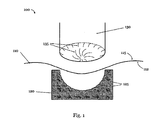
- Fig. 1 schematically shows a method 100 for manufacturing an outer layer for a panel of a ball, in particular a football.
- the method 100 comprises the shaping of a sheet of material 110 in a mold 120, wherein the mold 120 is formed in such a way, that the sheet of material 110 assumes a three-dimensional shape of the outer layer of the panel during shaping.
- the method 100 further comprises the creation of first textures in at least a first partial region on a first side 112 of the sheet of material 110 and the creation of second textures in at least a second partial region on a second side 115 of the sheet of material 110 .
- the method 100 may, as shown in Fig. 1 , comprise pressing a sheet of material 110 , here a plastic foil 110 , into a mold 120 with a plunger element 130.
- the mold 120 and the plunger element 130 are formed in such a way that during pressing the plastic foil 110 assumes a desired three-dimensional shape of the outer layer of the panel.
- the mold 120 is furthermore formed in such a way that during pressing, the mold 120 at least partially creates the first textures on the first side 112 and the plunger element 130 is formed in such a way the during pressing, it at least partially creates the second textures on the second side 115.
- the thickness and / or the material density of the plastic foil 110 may be influenced by pressing.
- the first textures are created at least partially during pressing by corresponding indentations 125 in the mold and the second textures are created at least partially during pressing by correspondingly protruding elements 135 on the plunger element 130, or vice versa.
- the shaping may, in particular, also comprise deep-drawing of the sheet of material 110 into the mold 120 and / or the sheet of material 110 may additionally be subjected to a heat treatment.
- the creation of the first and / or second textures may also be achieved in a different way or comprise other possibilities.
- the first textures may, in particular, at least partially be created by the mold 120 having corresponding indentations 125 and by inserting a flowable material (not shown) into the mold 120 before shaping of the sheet of material 110 .
- first and / or second textures are at least partially created by minting or high-pressure-forming.
- the sheet of material 110 may be pressed into the mold 120 by a focused high-pressure airstream, thereby creating the first and / or second textures at least partially.
- the sheet of material 110 need not be a plastic foil 110 , as shown here. Rather, the sheet of material 110 may, e.g., comprise a textile carrier, it may comprise one or more cast plastic layers or plastic layers applied otherwise or a plastic coat, and it may comprise further layers or components in addition to a plastic foil. Also, such textile carriers, plastic layers / coats or plastic foils may also be applied or added during or after the completion of the method 100 illustrated here.
- the first side 112 is preferably an outer side facing away from the panel of the ball and the second side 115 is an inner side facing towards the panel of the ball.
- inventive outer layers for ball panels which assume the desired three-dimensional shape of the surface of the ball panel, can be manufactured in a particularly simple manner while simultaneously imprinting the desired first and / or second textures on the latter.
- third textures are created with the method, which extend on the first side 112 of the plastic foil 110 and / or on the second side 115 of the plastic foil 110 and / or both on the first side 112 of the plastic foil 110 and on the second side 115 of the plastic foil 110 and which are created with additional indentations and / or protruding elements in the mold 120 or on the plunger element 130, respectively, which do not correspond to the indentations 125 and protruding elements 135 mentioned above for creating the first or second textures, respectively.
- This also includes textures "penetrating" the plastic foil 110: For example, during pressing the plunger element 130 may create an indentation-like texture on the second side 115 of the plastic foil 110 .
- this indentation-like texture may result in a corresponding texture on the first side 112 of the plastic foil 110 during pressing, depending on the precise shape of the mold 120 in this area (for example, if the mold 120 comprises a corresponding indentation in this area), so that the created third texture is not only located on one side of the plastic foil 110 , but quasi “penetrates" the plastic foil 110, as it were.
- the third textures only extend on the first side 112 and / or the second side 115 of the plastic foil 110 without penetrating it.
- the third textures on each of the two sides of the plastic foil 110 may be indentation-like as well as protruding third elements, which may be created during pressing by further indentations/protruding elements, for example, in the mold 120 or on the plunger element 130, respectively (which, as was mentioned already, may not correspond to the indentations 125 or the protruding elements 135, respectively).
- FIG. 1 is a strongly schematized illustration, which merely serves the purpose of clarifying the basic principle of the method according to the invention.
- the dimensions and precise design features, such as of the plastic foil 110 , the mold 120 including the indentations 125 and the plunger element 130 including protruding elements 135 do not necessarily represent the real conditions to be encountered when the method 100 according to the invention is actually used.
- the first textures comprise dimensions in the range from 0.1 mm to 0.5 mm, whereas the second textures comprise dimensions of less than 0.1 mm.
- the dimensions of the textures are to be understood as their typical spatial extension. This may, for example, be given by the depth or the diameter or the like being measured for a plurality of such textures and the measurement values being subsequently averaged (e.g. by arithmetic averaging).
- dimensions shall always refer to their depth and width, but not their length.
- textures with such dimensions are particularly suited for advantageously influencing the aerodynamic, haptic and optical properties of a ball panel or of a ball, respectively.
- the term "refraction of light” comprises the phenomenon of diffuse refraction of light and/or of light scattering as well as the generation of (punctual) light-reflexes and mirror-like effects.
- This allows the outer layer to be designed such that shadow-like effects, for example, are caused in individual partial regions of the outer layer, for example in regions in which the first and / or second textures cause absorption of light and / or scattering of light which is stronger compared to other regions of the outer layer.
- the plastic foil 110 is permeable for light at least in partial regions, e.g. in one or several partial regions in which first and / or second textures are located.
- a plastic foil 110 is to be considered permeable for light if it lets through at least a portion of the incident light, i.e. if it does not fully absorb and/or reflect the incident light, for example.
- a sheet of material 110 provided as a plastic foil 110 to have a thickness before shaping, in particular in the case of pressing, between 0.2 mm and 0.6 mm, particularly preferably between 0.2 mm and 0.4 mm.
- a plastic foil 110 of this thickness comprises a sufficient material thickness for impressing the desired textures and sufficient stability to meet the desired protection functions of the outer layer, for example, such as protection against abrasion, cuts, moisture, etc.
- it is also thin enough so as not to considerably increase the weight of the ball or negatively affect its deformability and behavior in case of kicks or hits.
- acrylonitrile-butadiene-styrene and / or thermoplastic (poly-) urethane have particularly proven advantageous as the materials for a plastic foil 110 for use with the manufacturing method 100 according to the invention described herein.
- These materials are particularly easy to process and comprise a combination of substance-specific properties which is advantageous for use in the method 100 described herein or variants thereof.
- the plastic foil 110 may additionally be subject to a heat treatment, as already mentioned before.
- the plastic foil 110 can be heated up and thus softened, for example, before it is inserted into the mold 120, so that its ability to assume the shape of the mold 120 and of the plunger element 130 is improved and so that impressing the first and / or second (and potentially third) textures by the indentations 125 or the protruding elements 135, respectively, (and potentially further indentations / protruding elements for the creation of the third textures) is furthermore facilitated.
- An embodiment of the method 100 according to the invention in which the plastic foil 110 is subject to such heat treatment during pressing is particularly preferred.
- the mold 120 and / or the plunger element 130 may for example be electrically heated or streamed through by a heated liquid.
- the plastic foil 110 may, for example, be suctioned or deep drawn against the mold 120 by negative pressure, as also already mentioned before.
- the mold 120 for example, comprises small openings (not shown), which are connected to a negative-pressure system (not shown, either).
- a thermoforming method comprises a particularly preferred embodiment of the inventive method 100.
- the plastic foil 110 may be subject to a cooling process or to cold treatment, respectively, either still inside the mold 120 or after it has been removed from the mold 120. This may be used for increasing dimensional stability and / or firmness of the outer layer created in that way, for example.
- the properties of the outer layer manufactured using the method 100 according to the invention can be further influenced.
- the plastic foil 110 is constructed from several layers.
- the plastic foil 110 comprises a base layer and a decoration layer.
- the base layer may assume the tasks which were already described above, such as providing a sufficient thickness for impressing the textures with a simultaneously sufficient protective function and flexibility, etc.
- the decoration layer may serve the optical design in a manner that is largely unaffected by these requirements.
- the plastic foil 110 comprises a base layer which comprises acrylonitrile-butadiene-styrene and / or thermoplastic (poly-) urethane, for example, at a thickness (before pressing) of 0.2 mm - 0.6 mm, preferably 0.2 mm - 0.4 mm, whereas the decoration layer comprises thermoplastic (poly-) urethane, for example at a thickness (before pressing) of 0 - 200 ⁇ m, preferably 90 ⁇ m - 110 ⁇ m.
- the decoration layer may furthermore comprise a light-reflecting material at least in partial regions, with a light-reflecting material being supposed to be understood herein as a material which reflects incident light almost completely, to a certain extent or even only a small proportion thereof, potentially dependent on the angle of incidence of the light or the angle of vision.
- the decoration layer can at least in partial regions, for example, also be colored, with colored, liquid thermoplastic (poly-) urethane, which is for example particularly resiliently affiliable with a decoration layer made from thermoplastic (poly-) urethane and is thus hardly influenced by abrasion.
- This also allows the decoration layer to be arranged on the first side 112 (the side facing away from the panel, for example) of the plastic foil 110 , with the base layer being arranged on the second side 115 (the side facing towards the panel) of the plastic foil 110 .
- a decoration layer which comprises a light-reflecting material at least in partial regions mirror-like optical effects can thus be created directly at the surface of the ball.
- optical effects can be created which go beyond a simple two-dimensional optical design, as e.g. impressing the surface of the ball.
- the outer layer may be applied, e.g. glued, onto the corresponding panel and / or connected with the panel by further pressure and / or heat treatment, and the finished ball can ultimately be manufactured from the panels manufactured in this way.
- the outer layer may be provided with a foamed plastic material on its back side to create an inventive panel. All these steps may also be performed during an integrated process within a manufacturing site or production line.
- Figs. 2a -f show the product 200 of a manufacturing method according to the invention. What can be seen is a plastic foil 210 which has undergone a method according to the invention, as described above in connection with Fig. 1 , for example.
- the entire plastic foil 210 is used as an outer layer for the panel of the ball for which the layer was manufactured here.
- the area 220 whose dimensions are suggested by the dashed line 225 in Fig. 2a , constitutes the actual outer layer for the ball panel.
- the projecting parts of the plastic foil 210 are cut off before or after the outer layer 220 is applied to the panel or a foamed panel material is provided to the back side of the outer layer 220 , for example.
- the outer layer 220 or the finished panel is die-cut from the plastic foil 210. (A marking corresponding to line 225 is not shown in Figs. 2b -f so as not to cover further details.) Further postprocessing steps may potentially follow.
- the finished ball can then ultimately be manufactured from such panels.
- Figs. 2a and 2b show a first side of the plastic foil 210 / of the outer layer 220 facing away from the panel of the ball
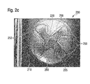
- Figs. 2c and 2d show a second side of the plastic foil 210 / the outer layer 220 facing towards the ball panel
- Fig. 2e once again shows the first side from a different view angle
- Fig. 2f illustrates the construction of the plastic foil 210 from a base layer 230 and a decoration layer 235 .
- the plastic foil 210 or rather the part 220 of the plastic foil 210 which is used as the outer layer for a ball panel, has first of all assumed the desired three-dimensional shape of the outer layer 220 due to the manufacturing process according to the invention, so that the outer layer 220 can be connected to the corresponding panel in an essentially (i.e. potentially up to corresponding first, second and / or third textures in the outer layer 220 ) form-fitted manner or be provided with a foamed material on its back side to create the panel.
- the plastic foil 210 may be subject to heat treatment, as was already mentioned, during or before the manufacturing method, for example.
- first textures are located in the first partial regions 240.
- the dimensions of these partial regions are suggested by the dotted line 245 in Fig. 2a ). These may, e.g. in case the shaping of the plastic foil 210 is carried out by pressing with a plunger element, be preferably created during pressing by corresponding indentations in the mold, as was already described above in connection with Fig. 1 .
- no further textures are located in the embodiment shown here, i.e. the first side of the outer layer 220 is essentially (i.e. apart from tolerances due to manufacturing) smooth outside the first partial areas 240.
- first textures are also located in other partial regions of the first side of the outer layer 220.
- Fig. 2b once again shows the first side of the embodiment 200 from an altered view angle and with a different incidence of light in contrast to Fig. 2a .
- this altered view angle results for example in a reflection of light in the area 280.
- Figs. 2c and 2d show the second side of the plastic foil 210 or of the outer layer 220 , respectively, facing towards the panel of the ball.
- second textures are located in the second partial regions 250, 252 and 255 (the extent of which is suggested by the solid line 258 in Fig. 2c ), which, e.g. in case the shaping of the plastic foil 210 is carried out by pressing with a plunger element, may be created during pressing by protruding elements on the plunger element, as was already described in connection with Fig. 1 .
- the plunger element was designed such that the outer layer 220 comprises different thicknesses and thus material densities after pressing in partial regions 250, 252 and 255. Particularly in combination with the first textures on the first side (cf. above), this results in different optical properties of the outer layer 220 in the various partial regions. For example, permeability for light/transparency of the outer layer is reduced in the partial regions 250 in contrast to the partial regions 252 and 255, so that a kind of shading effect or darkening effect is caused in the partial regions 250.
- the second side comprises third textures 260, which only extend on the second, inner side of the outer layer 220 and which are protruding elements which were created by corresponding indentations in the plunger element used for manufacture.
- third textures 260 are considerably larger in the embodiment shown here, for example in the range from 1 mm - 5 mm, than the dimensions of the first and second textures in the first partial regions 240 or the second partial regions 250, 252 and 255.
- the third textures influence the optical properties of the outer layer in a different manner than the first and / or second textures do, which further increases the design freedom for designing the outer layer of the panel/ball.
- Fig. 2d shows a further detailed view of the inside of the outer layer 220.
- the different thicknesses of the partial regions 250 and 252 which result in different optical properties of the outer layer 220 in these partial regions, can be seen.
- a reflection of light shows up in region 285, for example.
- Fig. 2e shows the first side, facing away from the panel, of the outer layer 220 made from the plastic foil 210 again, once more from a different perspective.
- the different optical properties of the outer layer 220 caused by the first textures in the first partial regions 240 of the first side and by the second textures in the various second partial regions 250, 252, 255 of the second side, as well as a reflection of light in region 288, for example, are visible.
- the plastic foil 210 comprises a base layer 230 as well as a decoration layer 235 in the present case.
- the base layer 230 comprises acrylonitrile-butadiene-styrene and thermoplastic (poly-) urethane
- the decoration layer 235 comprises thermoplastic (poly-) urethane and a thickness of approximately 100 ⁇ m, the base layer 230 being arranged on the side facing towards the panel and the decoration layer 235 being arranged on the side facing away from the panel.
- the decoration layer 235 comprises a material, at least in partial regions, which at least partially reflects incident light.
- this material and its distribution within the decoration layer 235 are designed such that the decoration layer 235 and thus also the outer layer 220 , depending on the angle of incidence of the light or on the view angle from which the decoration layer 235 is considered, reflects the light incident from the front (i.e. incident onto the side of the decoration layer 235 facing towards the viewer) largely or only in part, and therefore largely or at least partially "blinds out” light incident from the back (i.e. incident from the side of the decoration layer 235 facing away from the viewer) and crossing the decoration layer 235.
- the decoration layer 235 may result in the decoration layer 235 appearing non-permeable for light and like a mirror in case of strong reflection of the light incident from the front and thus a strong blinding out of the light incident from the back.
- the decoration layer 235 reflects the light incident from the side of the viewer in the direction of the arrow 238 almost completely in the region 237 and in this region almost completely blinds out light coming from the back of the decoration layer 235 and penetrating the decoration layer 235 from there.
- the decoration layer 235 appears non-permeable for light and like a mirror e.g. in the region 237 for someone looking at Fig. 2f . From another view angle or angle of incidence of the light, however, this behavior changes and the decoration layer 235 becomes at least partially transparent, cf. Figs. 2a and 2c , for example.
Landscapes
- Engineering & Computer Science (AREA)
- Mechanical Engineering (AREA)
- Health & Medical Sciences (AREA)
- General Health & Medical Sciences (AREA)
- Physical Education & Sports Medicine (AREA)
- Textile Engineering (AREA)
- Laminated Bodies (AREA)
- Casting Or Compression Moulding Of Plastics Or The Like (AREA)
- Blow-Moulding Or Thermoforming Of Plastics Or The Like (AREA)
- Physics & Mathematics (AREA)
- Thermal Sciences (AREA)
Abstract
Description
- The present invention relates to a method for manufacturing an outer layer for a panel of a ball, in particular a football, an outer layer manufactured with the method as well as a panel and a ball comprising such a layer.
- Balls, in particular sport balls, such as footballs, comprise a cover with a plurality of panels in many cases, which are sewed, glued or otherwise connected to each other. The panels are nowadays mostly made from plastics, but they may also comprise natural leather.
- For example,
EP 1424 105 B1 describes a method for manufacturing three-dimensional parts of a ball, in particular of a football, the parts comprising an outer material and a backing material, as well as a method for manufacturing a ball from such parts. - For the optical design of such balls, the surface of the individual panels or also of the completely assembled ball may be imprinted or sprayed with color, for example. However, on the one hand, this has the disadvantage that the optical design applied in this manner is rapidly impaired by abrasion or removed due to the influence of kicks, hits, bounces on the floor, etc. On the other hand, this process also only enables a simple two-dimensional optical design with colored patterns, images, graphical characters and the like. Effects which appear three-dimensional are not achievable or only difficult to achieve in this manner.
- In order to avoid the aforementioned abrasion, methods for the optical design of panels of a ball are known in the art which comprise imprinting a foil on its inside. The foil imprinted in this manner may be applied to a panel. Since the optical design elements are located on the inside of the foil, they are protected from abrasion by the foil to a large extent. Moreover, such a foil may also protect the panel of the ball itself from outer influences such as abrasion, moisture, sharp objects, etc.
- The aerodynamic properties of the ball made from the panels constitute a further factor to be taken into consideration in the manufacture of panels for balls. It has turned out, particularly with footballs, that a surface of the ball which is too smooth may have a negative effect on the flying properties and result in the ball "chattering", for example. Furthermore, a surface of a ball which is too smooth may also have negative effects on the usability of the ball, e.g. during a football match on a wet grass pitch.
- In order to avoid such effects, various structured surfaces or balls or individual panels of such balls are known in the art.
- For example,
DE 10 2009 016 287 B3 describes an inflatable ball, in particular a football, with an outer cover comprising a plurality of panels, the panels being connected with each other by seams and each panel comprising a pseudo-seam which extends at least along a part of the outer surface of the panel. Furthermore,DE 10 2009 016 287 B3 discloses that the panels may also comprise a surface texture. - Moreover,
US 2012/0172160 A1 discloses a game ball, such as a soccer ball, having a cover comprised of one or more cover panel blanks and one or more reinforcement material blanks. The cover panel blanks and reinforcement material blanks are heat bonded together so that the free edges and interior panel boundaries of the cover panel blanks are aligned with the reinforcement material blanks. -
EP 2 243 520 A1 discloses a ball having an outer shell comprising a plurality of panels, wherein the panels are interconnected by seams. Each panel comprises at least one pseudo-seam extending at least over a part of the outer surface of the panel. - It is a disadvantage of the ball panels or balls, respectively, known in the art, however, that the optical as well as the haptic and aerodynamic aspects are typically influenced by separate elements of the panels and the ball and that a plurality of different manufacturing steps and manufacturing devices are therefore required. This, on the one hand, makes the constructive set-up of such a ball more complicated, and on the other hand, the durability and resilience of the panels and the ball may suffer therefrom.
- Based on this prior art, it is therefore a problem underlying the present invention to provide simplified manufacturing methods for ball panels which allow influencing both the haptic and the aerodynamic properties of the panels in an advantageous way and to an improved extent while simultaneously increasing durability and resilience of the panels and the balls manufactured from them against external influences.
- According to an aspect of the invention, this problem is at least partially solved by a method for manufacturing an outer layer for a panel of a ball, in particular a football, wherein the method comprises shaping a sheet of material (e.g. essentially a two-dimensional material or a flat material) in a mold, wherein the mold is formed in such a way that during shaping, the sheet of material assumes a three-dimensional shape of the outer layer of the panel. Additionally, the method comprises creating first textures in at least a first partial region on a first side of the sheet of material and creating second textures in at least a second partial region on a second side of the sheet of material.
- Thus, the method according to the invention allows manufacturing, in a particularly easy manner, an outer layer for a panel of a ball, in particular a football, which can provide a plurality of functions.
- Assuming the desired three-dimensional shape facilitates the possibility that the outer layer for the panel of a ball manufactured from the sheet of material and the panel itself can be connected to each other in a largely form-fitted manner. On the one hand, this is advantageous in order to ensure the necessary stability of a ball manufactured from such inventive panels including outer layers, and, on the one hand, in order to largely avoid negatively affecting the game-play and usage properties of such a ball. In this way, the outer layer may in particular be provided with a foamed plastic material on its back side to create the panel.
- The creation of the first and / or second textures, which may preferably be effected and controlled independently from three-dimensionally shaping the sheet of material with the inventive method, allows advantageously influencing the aerodynamic and haptic as well as the optical properties of the finished panels or balls, respectively, in a plurality of ways. Herein, it is a particular advantage that the entire outer layer for a panel can be manufactured integrally, which leads to increased resilience and durability of the outer layer and thus ultimately also of the finished panels or balls, respectively.
- It is possible that shaping the sheet of material comprises pressing with a plunger element.
- For example, the shaping can be solely effected by such pressing, which constitutes a particularly easy procedural option. On the other hand, it is also possible that the shaping comprises further possibilities which will be described in the following. Moreover, analogous statements also apply to all other possibilities of shaping the sheet of material which are described herein.
- It is conceivable that the mold is formed in such a way that during pressing, the first textures are at least partially created, and that the plunger element is formed in such a way that during pressing, the second textures are at least partially created.
- When speaking about a partial creation of the textures in this context, this means that on the one hand, the textures may be solely created by the option currently discussed. On the other hand, however, further possibilities discussed herein may contribute to the creation of the textures.
- In particular, the first textures may at least partially be created during pressing by corresponding indentations in the mold and / or the second textures may at least partially be created during pressing by corresponding protruding elements on the plunger element. The opposite case is also possible, i.e. the first textures may at least partially be created during pressing by corresponding protruding elements in the mold and / or the second textures may at least partially be created during pressing by corresponding indentations in the plunger element. It is also conceivable that the mold or the plunger element, respectively, comprises both indentations as well as protruding elements that contribute to the creation of the first or second textures, respectively, during pressing.
- On the one hand, this allows largely doing without a pre-texturing of the sheet of material or the like. Moreover, molds or plunger elements with indentations or protruding elements, respectively, are particularly easy tools to manufacture and well suited for use within suitable manufacturing devices. Thus, the method according to the invention allows a particularly simple and economic manufacture of outer layers for ball panels according to the invention.
- It is also conceivable that shaping the sheet of material comprises deep-drawing into the mold.
- In this manner, it may be achieved that the sheet of material nestles against the mold particularly well and thereby, for example, takes over mold-textures that are present in the mold for the creation of the first textures, e.g. indentations or protruding elements, particularly well.
- It is also possible that the first textures are at least partially created by the mold having corresponding indentations - or more generally corresponding mold-textures in the mold - and by inserting a flowable (e.g. fluid) material into the mold before shaping the sheet of material.
- Such a flowable material may, for example, be (poly-) urethane or thermoplastic (poly-) urethane, which may be provided with a low viscosity. In this manner, also subtle and complex first textures may be created, which may not or only under significantly increased effort be created solely by pressing into a mold with indentations or protruding elements, respectively.
- It is mentioned here that the use of such a flowable material can, in principle, also be used for the creation of the second textures or contribute to it.
- Moreover, it is conceivable that the first textures and / or the second textures are at least partially created by minting or high-pressure-forming, for example by use of a highly focused airstream with high pressure, or a combination thereof. It is once again mentioned that the different possibilities for creating the first and / or second textures may be appropriately combined.
- These further options may again enlarge the spectrum of first and second textures that may be created.
- The sheet of material may additionally be subjected to a heat treatment. Here, the heat treatment may occur before shaping of the sheet of material, for example before pressing or deep-drawing, but also simultaneously with shaping in the sense of a thermoforming process. The deformability of the sheet of material can be increased by the heat treatment, for example, so that the manufacturing process is facilitated and the creation of the first and second textures, respectively, is also facilitated. After such a manufacturing process has been completed, an additional cooling process may additionally be carried out, which results in an at least partial hardening of the sheet of material and thus the manufactured outer layer for the panel and in an increase of their stability.
- For example, the first side is an outer side of the sheet of material facing away from the panel of the ball and the second side is an inner side of the sheet of material facing towards the panel of the ball.
- Thus, the first textures on the first side, for example, may primarily serve the purpose of influencing the haptic and aerodynamic properties of a panel or ball, respectively, equipped with such an outer layer, whereas the second textures on the second side may primarily serve the optical design and are largely protected from outer influences. However, it is also possible that the first textures and / or the second textures each serve the purpose of influencing the haptic and aerodynamic as well as the optical properties.
- Influencing the haptic properties may on the one hand improve the feeling when using the ball and its general appearance. The influence may, however, also affect technical characteristics of the ball, e.g. increase its grip and contact surface. The possibilities of influencing the optical properties increase the design freedom for the manufacture of balls and may allow for a customization.
- Optionally, third textures are additionally created, e.g. during pressing or deep-drawing, which extend on the first side and / or on the second side and / or on the first side as well as on the second side of the sheet of material.
- Such third textures may, for example, be created during pressing by further indentations and / or protruding elements in the mold and / or on the plunger element. For example, by an indentation in the mold and a corresponding protruding element on the plunger element, third textures "penetrating" the sheet of material may be created which are designed such that a protrusion is created on the first side of the sheet of material and a corresponding indentation is created on the second side of the sheet of material, or vice versa. In other embodiments of the method, the third textures only extend on the first and / or the second side, without "penetrating" the sheet of material, and the third textures may be both indentation-like and protruding textures. Moreover, the further possibilities for the creation of the first and / or second textures discussed herein may also contribute to the creation of the third textures. Such third textures, for example, allow further influencing the haptic, aerodynamic and optical properties of the outer layer for panels or balls, respectively. It is also possible that the third textures form "sub-textures" within the first and / or second textures or, vice versa, that the first and / or second textures form "sub-textures" within the third textures.
- It is conceivable that the first textures comprise dimensions of 0.1 mm - 0.5 mm. First textures of such dimensions, for example, have a particularly advantageous effect on the aerodynamic properties, e.g. steadiness of flight, and the haptic properties, e.g. "grip" in case of moisture.
- Moreover, the second textures may comprise dimensions of less than 0.1 mm. Second textures of such dimensions are particularly well suited for influencing the optical properties of the outer layer, for example by refraction of light.
- In particular, the first and / or the second textures, and potentially the third textures, too, may evoke an absorption of light and / or a refraction of light. This may, as was already mentioned, further influence the appearance of the finished panel or ball, respectively, including the outer layer manufactured according to the invention, particularly when subject to the incidence of light. This may, in particular, cause effects which appear three-dimensional. For example, under the incidence of light, a change of color of the outer layer may be effected depending on the depth of the first, second and potentially third textures.
- It is conceivable that the sheet of material comprises a textile carrier. The textile carrier may comprise a fiber-reinforced material, a fleece material, a finely knitted material, a woven material or a felt material. Moreover, the textile carrier may have an optical design printed on it.
- The textile carrier may thus serve to influence the optical as well as haptic and aerodynamic properties. It may also increase the tear resistance of the outer layer.
- It is further conceivable that the sheet of material comprises a plastic layer, for example a cast plastic layer and in particular a cast plastic coat. It is, in particular, possible that a sheet of material with a textile carrier comprises a cast plastic layer or a cast plastic coat, respectively.
- The cast plastic layer or the cast plastic coat may, e.g., be a transparent layer or a transparent coat, respectively, such that an underlying layer or optical design may remain visible. As possible materials for the plastic layer / the plastic coat, e.g. (poly-) urethane or thermoplastic (poly-) urethane may be considered. These materials lead to a haptically valuable and largely UV-resistant surface, in particular for a plastic layer provided on the first side facing away from the panel. Furthermore, these materials may be provided with a low viscosity, which facilitates the application of the plastic layer or the plastic coat, respectively.
- It is conceivable in this regard, that the plastic layer is only cast on the first side of the sheet of material or only on the second side. In principle, it is also possible that the plastic layer is applied by a method different from casting, e.g. by spraying or the like.
- Further, it is conceivable that the plastic layer is applied to both sides of the sheet of material and thus forms a plastic coat. It is, however, also possible that the plastic material is arranged within the interior of the sheet of material, and so forth. The plastic layer or the plastic coat may moreover be applied in a partial region of the sheet of material only, for example in partial region where the first or second textures, respectively, are created.
- It is further mentioned here that such a plastic layer or a plastic coat may also be applied to the sheet of material during the shaping of the sheet of material and / or the creation of the first, second and potentially third textures. In principle, it is also possible that the plastic layer or the plastic coat is only applied to the sheet of material after the remaining procedure, in particular only after the shaping of the sheet of material and the creation of the first, second and potentially third textures, has been completed, such that the plastic layer or the plastic coat, respectively, cover the textures and protect them from abrasion and other adverse influences.
- It is also possible that the sheet of material comprises a plastic foil.
- The sheet of material may, for example, consist of a plastic foil. It is thus conceivable that the outer layer is manufactured by pressing a plastic foil with a plunger element into a mold.
- Also here, however, reference is made to the possibility that such a plastic foil is only applied to the sheet of material during or after completion of the remaining process for the manufacture of the outer layer, for example by way of a further deep-drawing process and for example on the outer side facing away from the panel of the ball, such that the foil may cover the textures and protect them from abrasion and other adverse influences. Also, the application of multiple plastic foils is possible in this regard, or a combination with the application of a plastic layer or a plastic coat, respectively, cf. above.
- Finally, reference is made to the possibility that such a plastic foil itself comprises a layered construction, as further illustrated below by way of a specific example having a base layer and a decoration layer.
- In summary, the sheet of material may already comprise a layered construction in its base state, i.e. before shaping of the sheet of material and creation of the first, second and potentially third textures. Alternatively, further layers, like one or more of the above described plastic layers or a plastic coat or one or more plastic foils or textile layers, may be applied to the sheet of material during or after completion of the remaining procedure, in particular during or after shaping of the sheet of material and /or creation of the first, second and potentially third textures. One might think of an injection molded thermoset reinforcement layer or a design foil, for example on the inner side facing towards the panel of the ball.
- It is, in particular, possible that the plastic foil is permeable for light at least in a partial region. Hence, the light may, for example, advance through the plastic foil to the second textures on the second, e.g. inner side of the plastic foil and be reflected, mirrored, refracted, scattered, etc. This may influence the optical appearance of the finished panel or ball, respectively, particularly when subject to the incidence of light. Furthermore, a plastic foil which is at least partially permeable for light may allow the panel of the ball underneath it to be at least partially visible.
- It is possible that the plastic foil comprises a thickness before shaping, in particular before pressing, of 0.2 mm - 0.6 mm, preferably a thickness of 0.2 mm - 0.4 mm.
- Such a thickness constitutes a preferred compromise between a thickness which is selected sufficiently large to enable the desired influence of the properties of the panel or the ball, respectively, and which, on the other hand, is low enough so as not or not significantly to affect negatively the weight and other properties which are relevant to the use.
- The plastic foil may, for example, comprise one of several of the following materials: acrylonitrile-butadiene-styrene, thermoplastic (poly-) urethane.
- These materials have proven particularly advantageous for manufacturing an outer layer as described herein, particularly using the methods according to the invention described herein. In this regard, each of these materials entails its specific substance and processing properties, which may be used or combined with each other advantageously depending on the profile of requirements.
- As a further possibility, the plastic foil may comprise a layered construction, in particular a base layer and a decoration layer. Furthermore, such a plastic foil with layered construction may also comprise a reinforcement layer, for example a textile carrier as discussed above.
- Herein, the base layer, for example, comprises acrylonitrile-butadiene-styrene and / or thermoplastic (poly-) urethane and the decoration layer preferably comprises thermoplastic (poly-) urethane and a thickness of 0 µm - 200 µm, particularly preferably a thickness of 90 µm - 110 µm.
- The base layer may, for example, provide the necessary basic stability and thickness of the plastic foil which is necessary for creating the first, second and potentially third textures, while the decoration layer provides a further possibility for optical design, which can be applied essentially independently from or also in combination with the further possibilities discussed herein for optical, haptic and aerodynamic design. In this context, the materials and layer thicknesses specified above have proven particularly advantageous.
- It is conceivable that the decoration layer is arranged on the first side of the plastic foil and the base layer is arranged on the second side of the plastic foil. This set-up allows, in particular, additionally influencing the optical properties directly at the surface of the finished panel or ball, respectively, while it is also possible that the danger of abrasion of the decoration layer serving the purpose of optical design is largely avoided due to the tight and potentially integral connection of the decoration layer and the base layer. A different set-up is, however, also possible. For example, the arrangement of the base layer in relation to the decoration layer may change locally, the base layer and the decoration layer may e.g. constitute two interwoven layers.
- It is further possible that the decoration layer comprises a light-reflecting material. The reflectivity may be developed to different degrees. In particular, the decoration layer may appear matt or glossy. The light reflecting material may, e.g., be used in order to create the impression of three-dimensional design effects, in particular in combination with the possibilities for optical design described herein.
- Further aspects of the invention relate to an outer layer for a panel of a ball, in particular of a football, manufactured with one of the methods described herein, a panel of a ball, in particular of a football, which comprises such an outer layer, as well as a ball, in particular a football, manufactured from such panels.
- Such a panel may, for example, be manufactured by providing an inventive outer layer with a foamed plastic material on its back side. From such panels, a finished ball may be manufactured by sewing, gluing or welding of the panels.
- Panels or balls, respectively, with an outer layer manufactured according to the invention particularly comprise, as was already mentioned, the advantage that the outer layer provides protection from external influences such as abrasion, carves or cuts, moisture and the like, while simultaneously allowing the aerodynamic and haptic as well as optical properties of the panel or ball, respectively, to be influenced advantageously and essentially independently from one another, or also in combination, with reduced production efforts.
- A further advantage of the inventive method is the possibility of an automated production process, at least to a large degree. For example, the desired structure and design of an outer layer, or a panel or a ball, to be produced may first be created within a 3D-simulation. Based on this simulation, a manufacturing site may be caused to manufacture the corresponding outer layer, or already the complete panel or ball. The computation of the necessary manufacturing- and control-parameters may take into account the rounded form of the product. During this process, the design of the outer layer may be adapted to the coloring of elements lying below, for example of a foamed panel material used in the creation of the panel.
- Presently preferred exemplary designs and embodiments of the methods and products according to the invention are described in the following detailed description, with reference to the following figures:
- Fig. 1:
- An exemplary embodiment of a method according to the invention for manufacturing an outer layer for a panel of a ball, in particular a football.
- Figs. 2a-f:
- An exemplary embodiment of an outer layer for a panel of a ball, in particular a football, according to the invention, which was manufactured using one of the methods described herein.
- In the following detailed description, presently preferred embodiments of the invention will be described primarily with regard to methods and products for the manufacture of footballs. However, it is emphasized that the present invention is not limited to this area but may also be used in the manufacture of other types of balls or more generally sporting goods.
- It also has to be taken into consideration that, depending on the profile of requirements for the respective panel or the respective ball, various ones of the described aspects and steps can be advantageously combined with each other or individual aspects or steps may be left unconsidered provided that they are not relevant to the respective panel, the respective ball or the respective good. Such embodiments are also to be considered as being part of the invention.
-
Fig. 1 schematically shows amethod 100 for manufacturing an outer layer for a panel of a ball, in particular a football. - The
method 100 comprises the shaping of a sheet ofmaterial 110 in amold 120, wherein themold 120 is formed in such a way, that the sheet ofmaterial 110 assumes a three-dimensional shape of the outer layer of the panel during shaping. Themethod 100 further comprises the creation of first textures in at least a first partial region on afirst side 112 of the sheet ofmaterial 110 and the creation of second textures in at least a second partial region on asecond side 115 of the sheet ofmaterial 110. - All connected or disconnected parts of the respective side of the sheet of material shall be understood as a partial region.
- The
method 100 may, as shown inFig. 1 , comprise pressing a sheet ofmaterial 110, here aplastic foil 110, into amold 120 with aplunger element 130. Themold 120 and theplunger element 130 are formed in such a way that during pressing theplastic foil 110 assumes a desired three-dimensional shape of the outer layer of the panel. Themold 120 is furthermore formed in such a way that during pressing, themold 120 at least partially creates the first textures on thefirst side 112 and theplunger element 130 is formed in such a way the during pressing, it at least partially creates the second textures on thesecond side 115. Moreover, the thickness and / or the material density of theplastic foil 110 may be influenced by pressing. - For example, the first textures are created at least partially during pressing by corresponding
indentations 125 in the mold and the second textures are created at least partially during pressing by correspondingly protrudingelements 135 on theplunger element 130, or vice versa. - Further embodiments of the method are, however, also conceivable, as already described in detail further above. The shaping may, in particular, also comprise deep-drawing of the sheet of
material 110 into themold 120 and / or the sheet ofmaterial 110 may additionally be subjected to a heat treatment. - The creation of the first and / or second textures may also be achieved in a different way or comprise other possibilities. The first textures may, in particular, at least partially be created by the
mold 120 having correspondingindentations 125 and by inserting a flowable material (not shown) into themold 120 before shaping of the sheet ofmaterial 110. - It is also possible that the first and / or second textures are at least partially created by minting or high-pressure-forming. For example, the sheet of
material 110 may be pressed into themold 120 by a focused high-pressure airstream, thereby creating the first and / or second textures at least partially. - Moreover, the sheet of
material 110 need not be aplastic foil 110, as shown here. Rather, the sheet ofmaterial 110 may, e.g., comprise a textile carrier, it may comprise one or more cast plastic layers or plastic layers applied otherwise or a plastic coat, and it may comprise further layers or components in addition to a plastic foil. Also, such textile carriers, plastic layers / coats or plastic foils may also be applied or added during or after the completion of themethod 100 illustrated here. - For the reason of simplification, the
method 100 illustrated inFig. 1 will in the following be further discussed for the special case of the pressing of aplastic foil 110. It will be apparent to the skilled person, however, that all further possibilities mentioned herein mays also be used. Insofar, reference is made to the more detailed considerations put forth in section 3. ("Summary of the invention") of this document. - The
first side 112 is preferably an outer side facing away from the panel of the ball and thesecond side 115 is an inner side facing towards the panel of the ball. - For example, by means of a combination of a
mold 120 withindentations 125 and aplunger element 130 withprotruding elements 135, inventive outer layers for ball panels, which assume the desired three-dimensional shape of the surface of the ball panel, can be manufactured in a particularly simple manner while simultaneously imprinting the desired first and / or second textures on the latter. - Optionally, it is also possible for third textures to be created with the method, which extend on the
first side 112 of theplastic foil 110 and / or on thesecond side 115 of theplastic foil 110 and / or both on thefirst side 112 of theplastic foil 110 and on thesecond side 115 of theplastic foil 110 and which are created with additional indentations and / or protruding elements in themold 120 or on theplunger element 130, respectively, which do not correspond to theindentations 125 and protrudingelements 135 mentioned above for creating the first or second textures, respectively. This also includes textures "penetrating" the plastic foil 110: For example, during pressing theplunger element 130 may create an indentation-like texture on thesecond side 115 of theplastic foil 110. If the dimensions of this indentation-like texture are large enough in relation to the thickness of theplastic foil 110, this may result in a corresponding texture on thefirst side 112 of theplastic foil 110 during pressing, depending on the precise shape of themold 120 in this area (for example, if themold 120 comprises a corresponding indentation in this area), so that the created third texture is not only located on one side of theplastic foil 110, but quasi "penetrates" theplastic foil 110, as it were. In contrast, in other embodiments, the third textures only extend on thefirst side 112 and / or thesecond side 115 of theplastic foil 110 without penetrating it. Here, the third textures on each of the two sides of theplastic foil 110 may be indentation-like as well as protruding third elements, which may be created during pressing by further indentations/protruding elements, for example, in themold 120 or on theplunger element 130, respectively (which, as was mentioned already, may not correspond to theindentations 125 or theprotruding elements 135, respectively). - It has to be taken into consideration in this regard that the illustration of
Fig. 1 is a strongly schematized illustration, which merely serves the purpose of clarifying the basic principle of the method according to the invention. Herein, the dimensions and precise design features, such as of theplastic foil 110, themold 120 including theindentations 125 and theplunger element 130 includingprotruding elements 135 do not necessarily represent the real conditions to be encountered when themethod 100 according to the invention is actually used. - Preferably, the first textures comprise dimensions in the range from 0.1 mm to 0.5 mm, whereas the second textures comprise dimensions of less than 0.1 mm. Here, the dimensions of the textures are to be understood as their typical spatial extension. This may, for example, be given by the depth or the diameter or the like being measured for a plurality of such textures and the measurement values being subsequently averaged (e.g. by arithmetic averaging).
- For channel-like textures, "dimensions" shall always refer to their depth and width, but not their length.
- As will be discussed in more detail in connection with the embodiment of an inventive
outer layer 220 for a panel of a ball shown inFigs. 2a -f, textures with such dimensions are particularly suited for advantageously influencing the aerodynamic, haptic and optical properties of a ball panel or of a ball, respectively. - Here, it is particularly advantageous for influencing the optical design features of the panel or of the ball, respectively, if the first and / or the second textures are designed such that they may cause absorptions of light and / or refractions of light. In the context of this document, the term "refraction of light" comprises the phenomenon of diffuse refraction of light and/or of light scattering as well as the generation of (punctual) light-reflexes and mirror-like effects. This allows the outer layer to be designed such that shadow-like effects, for example, are caused in individual partial regions of the outer layer, for example in regions in which the first and / or second textures cause absorption of light and / or scattering of light which is stronger compared to other regions of the outer layer. Due to the combination of such textures, it is particularly possible to create optical effects which appear three-dimensional, i.e. effects which go beyond a simple two-dimensional optical design of the surface of the panel or the ball, respectively. In this regard, it is furthermore advantageous if the
plastic foil 110 is permeable for light at least in partial regions, e.g. in one or several partial regions in which first and / or second textures are located. In this regard, aplastic foil 110 is to be considered permeable for light if it lets through at least a portion of the incident light, i.e. if it does not fully absorb and/or reflect the incident light, for example. - In order to enable the first and / or second (and potentially third) textures being created while simultaneously not excessively negatively affecting the weight and other properties relevant to game-play, it has proven particularly advantageous for a sheet of
material 110 provided as aplastic foil 110 to have a thickness before shaping, in particular in the case of pressing, between 0.2 mm and 0.6 mm, particularly preferably between 0.2 mm and 0.4 mm. Aplastic foil 110 of this thickness comprises a sufficient material thickness for impressing the desired textures and sufficient stability to meet the desired protection functions of the outer layer, for example, such as protection against abrasion, cuts, moisture, etc. On the other hand, however, it is also thin enough so as not to considerably increase the weight of the ball or negatively affect its deformability and behavior in case of kicks or hits. In this regard, particularly sufficient deformability of the outer layer has to be maintained, since an outer layer of a panel or ball, respectively, which is too rigid might otherwise easily cause injuries to a player (e.g. a footballer when kicking or of a volleyball player when hitting) and might furthermore negatively affect the elasticity properties of the ball. - In order to meet these requirements, acrylonitrile-butadiene-styrene and / or thermoplastic (poly-) urethane have particularly proven advantageous as the materials for a
plastic foil 110 for use with themanufacturing method 100 according to the invention described herein. These materials are particularly easy to process and comprise a combination of substance-specific properties which is advantageous for use in themethod 100 described herein or variants thereof. - In order to facilitate the three-dimensional shaping of the
plastic foil 110 and the creation of the first and / or second (and potentially third) textures, theplastic foil 110 may additionally be subject to a heat treatment, as already mentioned before. For example, theplastic foil 110 can be heated up and thus softened, for example, before it is inserted into themold 120, so that its ability to assume the shape of themold 120 and of theplunger element 130 is improved and so that impressing the first and / or second (and potentially third) textures by theindentations 125 or theprotruding elements 135, respectively, (and potentially further indentations / protruding elements for the creation of the third textures) is furthermore facilitated. An embodiment of themethod 100 according to the invention in which theplastic foil 110 is subject to such heat treatment during pressing is particularly preferred. For this purpose, themold 120 and / or theplunger element 130 may for example be electrically heated or streamed through by a heated liquid. - In order to further optimize the
manufacturing process 100, theplastic foil 110 may, for example, be suctioned or deep drawn against themold 120 by negative pressure, as also already mentioned before. For this purpose, themold 120, for example, comprises small openings (not shown), which are connected to a negative-pressure system (not shown, either). Such a thermoforming method comprises a particularly preferred embodiment of theinventive method 100. Furthermore, theplastic foil 110 may be subject to a cooling process or to cold treatment, respectively, either still inside themold 120 or after it has been removed from themold 120. This may be used for increasing dimensional stability and / or firmness of the outer layer created in that way, for example. It is apparent to a person skilled in the art that by suitably varying the manufacturing parameters, such as pressure or forming pressure, duration and temperature of the heat treatment and / or the cold treatment as well as the starting material and the starting thickness of theplastic foil 110, etc., the properties of the outer layer manufactured using themethod 100 according to the invention, particularly its dimensional stability and flexibility, can be further influenced. - In order to enable even further influencing, in particular, the optical properties of the panel or ball, respectively, it is furthermore advantageous of the
plastic foil 110 is constructed from several layers. Here, it is particularly preferable if theplastic foil 110 comprises a base layer and a decoration layer. Herein, the base layer may assume the tasks which were already described above, such as providing a sufficient thickness for impressing the textures with a simultaneously sufficient protective function and flexibility, etc., whereas the decoration layer may serve the optical design in a manner that is largely unaffected by these requirements. In a particularly preferred embodiment, theplastic foil 110 comprises a base layer which comprises acrylonitrile-butadiene-styrene and / or thermoplastic (poly-) urethane, for example, at a thickness (before pressing) of 0.2 mm - 0.6 mm, preferably 0.2 mm - 0.4 mm, whereas the decoration layer comprises thermoplastic (poly-) urethane, for example at a thickness (before pressing) of 0 - 200 µm, preferably 90 µm - 110 µm. - For the optical design, the decoration layer may furthermore comprise a light-reflecting material at least in partial regions, with a light-reflecting material being supposed to be understood herein as a material which reflects incident light almost completely, to a certain extent or even only a small proportion thereof, potentially dependent on the angle of incidence of the light or the angle of vision.
- Moreover, the decoration layer can at least in partial regions, for example, also be colored, with colored, liquid thermoplastic (poly-) urethane, which is for example particularly resiliently affiliable with a decoration layer made from thermoplastic (poly-) urethane and is thus hardly influenced by abrasion. This also allows the decoration layer to be arranged on the first side 112 (the side facing away from the panel, for example) of the
plastic foil 110, with the base layer being arranged on the second side 115 (the side facing towards the panel) of theplastic foil 110. Especially in connection with a decoration layer which comprises a light-reflecting material at least in partial regions mirror-like optical effects can thus be created directly at the surface of the ball. In combination with the first textures located on thefirst side 112 extending throughout the decoration layer and potentially also the part of the base layer adjacent to the decoration layer, as well as second textures lying underneath that and extending, e.g., on thesecond side 115 of the base layer facing towards the panel, optical effects can be created which go beyond a simple two-dimensional optical design, as e.g. impressing the surface of the ball. - After completion of the method steps of the
manufacturing method 100 according to the invention described herein, potentially superfluous parts of theplastic foil 110, which are not required for the outer layer of the panel (cf.Figs. 2a -f), may be removed and / or further postprocessing steps on the outer layer manufactured with theinventive method 100 may follow, for example the application of further plastic foils, plastic layers, plastic coats, reinforcement layers or decoration layers, as already mentioned numerous times. After this, the outer layer may be applied, e.g. glued, onto the corresponding panel and / or connected with the panel by further pressure and / or heat treatment, and the finished ball can ultimately be manufactured from the panels manufactured in this way. Alternatively, the outer layer may be provided with a foamed plastic material on its back side to create an inventive panel. All these steps may also be performed during an integrated process within a manufacturing site or production line. -
Figs. 2a -f show theproduct 200 of a manufacturing method according to the invention. What can be seen is aplastic foil 210 which has undergone a method according to the invention, as described above in connection withFig. 1 , for example. - What has to be taken into consideration with these figures, first of all, is that not the entire
plastic foil 210 is used as an outer layer for the panel of the ball for which the layer was manufactured here. Merely thearea 220, whose dimensions are suggested by the dashedline 225 inFig. 2a , constitutes the actual outer layer for the ball panel. The projecting parts of theplastic foil 210 are cut off before or after theouter layer 220 is applied to the panel or a foamed panel material is provided to the back side of theouter layer 220, for example. As a further possibility, theouter layer 220 or the finished panel is die-cut from theplastic foil 210. (A marking corresponding toline 225 is not shown inFigs. 2b -f so as not to cover further details.) Further postprocessing steps may potentially follow. The finished ball can then ultimately be manufactured from such panels. - Here,
Figs. 2a and2b show a first side of theplastic foil 210 / of theouter layer 220 facing away from the panel of the ball, whereasFigs. 2c and2d show a second side of theplastic foil 210 / theouter layer 220 facing towards the ball panel.Fig. 2e once again shows the first side from a different view angle andFig. 2f illustrates the construction of theplastic foil 210 from abase layer 230 and adecoration layer 235. - As can be seen from
Figs. 2a -f, first of all, theplastic foil 210, or rather thepart 220 of theplastic foil 210 which is used as the outer layer for a ball panel, has first of all assumed the desired three-dimensional shape of theouter layer 220 due to the manufacturing process according to the invention, so that theouter layer 220 can be connected to the corresponding panel in an essentially (i.e. potentially up to corresponding first, second and / or third textures in the outer layer 220) form-fitted manner or be provided with a foamed material on its back side to create the panel. In order to enable this three-dimensional shaping, among other things, theplastic foil 210 may be subject to heat treatment, as was already mentioned, during or before the manufacturing method, for example. - On the first side of the
outer layer 220, i.e. the side facing away from the panel of theouter layer 220, first textures are located in the firstpartial regions 240. (The dimensions of these partial regions are suggested by the dottedline 245 inFig. 2a ). These may, e.g. in case the shaping of theplastic foil 210 is carried out by pressing with a plunger element, be preferably created during pressing by corresponding indentations in the mold, as was already described above in connection withFig. 1 . In the remaining partial regions of the first side of theouter layer 220, no further textures are located in the embodiment shown here, i.e. the first side of theouter layer 220 is essentially (i.e. apart from tolerances due to manufacturing) smooth outside the firstpartial areas 240. - In other embodiments, first textures are also located in other partial regions of the first side of the
outer layer 220. -
Fig. 2b once again shows the first side of theembodiment 200 from an altered view angle and with a different incidence of light in contrast toFig. 2a . As will be described in detail below, this altered view angle results for example in a reflection of light in thearea 280. -
Figs. 2c and2d show the second side of theplastic foil 210 or of theouter layer 220, respectively, facing towards the panel of the ball. On this second side, second textures are located in the secondpartial regions solid line 258 inFig. 2c ), which, e.g. in case the shaping of theplastic foil 210 is carried out by pressing with a plunger element, may be created during pressing by protruding elements on the plunger element, as was already described in connection withFig. 1 . - In the embodiment shown here, the plunger element was designed such that the
outer layer 220 comprises different thicknesses and thus material densities after pressing inpartial regions outer layer 220 in the various partial regions. For example, permeability for light/transparency of the outer layer is reduced in thepartial regions 250 in contrast to thepartial regions partial regions 250. - Moreover, in the embodiment shown here, the second side comprises
third textures 260, which only extend on the second, inner side of theouter layer 220 and which are protruding elements which were created by corresponding indentations in the plunger element used for manufacture. - The dimensions of these
third textures 260 are considerably larger in the embodiment shown here, for example in the range from 1 mm - 5 mm, than the dimensions of the first and second textures in the firstpartial regions 240 or the secondpartial regions -
Fig. 2d shows a further detailed view of the inside of theouter layer 220. Here, the different thicknesses of thepartial regions outer layer 220 in these partial regions, can be seen. Furthermore, due to the view angle and angle of incidence of the light which has been altered in contrast toFig. 2c , a reflection of light shows up inregion 285, for example. -
Fig. 2e , in contrast, shows the first side, facing away from the panel, of theouter layer 220 made from theplastic foil 210 again, once more from a different perspective. The different optical properties of theouter layer 220 caused by the first textures in the firstpartial regions 240 of the first side and by the second textures in the various secondpartial regions region 288, for example, are visible. - As can further be seen from
Fig. 2f , theplastic foil 210 comprises abase layer 230 as well as adecoration layer 235 in the present case. Here, thebase layer 230 comprises acrylonitrile-butadiene-styrene and thermoplastic (poly-) urethane, whereas thedecoration layer 235 comprises thermoplastic (poly-) urethane and a thickness of approximately 100 µm, thebase layer 230 being arranged on the side facing towards the panel and thedecoration layer 235 being arranged on the side facing away from the panel. - Moreover, the
decoration layer 235 comprises a material, at least in partial regions, which at least partially reflects incident light. In the present case, this material and its distribution within thedecoration layer 235 are designed such that thedecoration layer 235 and thus also theouter layer 220, depending on the angle of incidence of the light or on the view angle from which thedecoration layer 235 is considered, reflects the light incident from the front (i.e. incident onto the side of thedecoration layer 235 facing towards the viewer) largely or only in part, and therefore largely or at least partially "blinds out" light incident from the back (i.e. incident from the side of thedecoration layer 235 facing away from the viewer) and crossing thedecoration layer 235. This may result in thedecoration layer 235 appearing non-permeable for light and like a mirror in case of strong reflection of the light incident from the front and thus a strong blinding out of the light incident from the back. In the view angle shown inFig. 2f , for example, thedecoration layer 235 reflects the light incident from the side of the viewer in the direction of thearrow 238 almost completely in theregion 237 and in this region almost completely blinds out light coming from the back of thedecoration layer 235 and penetrating thedecoration layer 235 from there. Thus, thedecoration layer 235 appears non-permeable for light and like a mirror e.g. in theregion 237 for someone looking atFig. 2f . From another view angle or angle of incidence of the light, however, this behavior changes and thedecoration layer 235 becomes at least partially transparent, cf.Figs. 2a and2c , for example. - Whereas in the above discussion of the embodiment shown in
Figs. 2a -f, the optical properties of the outer layer or of the panel/ball were mainly talked about, it is apparent to the person skilled in the art, however, that the possibilities of influence discussed here may at least also partially serve the purpose of influencing the haptic and/or aerodynamic properties. - In the following, further embodiments are described to facilitate the understanding of the invention:
- 1. Method for manufacturing an outer layer for a panel of a ball, in particular a football, wherein the method comprises:
- a. shaping of a sheet of material in a mold,
- b. wherein the mold is formed in such a way that during shaping, the sheet of material assumes a three-dimensional shape of the outer layer of the panel;
- c. creating first textures in at least a first partial region on a first side of the sheet of material; and
- d. creating second textures in at least a second partial region on a second side of the sheet of material.
- 2. Method according to embodiment 1, wherein shaping the sheet of material comprises pressing with a plunger element.
- 3. Method according to embodiment 2, wherein the mold is formed in such a way that during pressing, the mold at least partially creates the first textures, and wherein the plunger element is formed in such a way that during pressing, the plunger element at least partially creates the second textures.
- 4. Method according to embodiment 3, wherein the first textures are at least partially created during pressing by corresponding indentations in the mold and / or wherein the second textures are at least partially created during pressing by corresponding protruding elements on the plunger element, or vice versa.
- 5. Method according to one of the preceding embodiments, wherein shaping the sheet of material comprises deep-drawing into the mold.
- 6. Method according to one of the preceding embodiments, wherein the first textures are at least partially created by the mold having corresponding indentations and by inserting a flowable material into the mold before shaping the sheet of material.
- 7. Method according to one of the preceding embodiments, wherein the first textures and / or the second textures are at least partially created by minting or high-pressure-forming.
- 8. Method according to one of the preceding embodiments, wherein the sheet of material is additionally subjected to a heat treatment.
- 9. Method according to one of the preceding embodiments, wherein the first side is an outer side of the sheet of material facing away from the panel of the ball and wherein the second side is an inner side of the sheet of material facing towards the panel of the ball.
- 10. Method according to one of the preceding embodiments, wherein third textures are additionally created, which extend along the first side and / or along the second side and / or along the first side as well as the second side.
- 11. Method according to one of the preceding embodiments, wherein the first textures comprise dimensions of 0.1 mm - 0.5 mm.
- 12. Method according to one of the preceding embodiments, wherein the second textures comprise dimensions of less than 0.1 mm.
- 13. Method according to one of the preceding embodiments, wherein the first textures and / or the second textures can evoke an absorption of light and / or a refraction of light.
- 14. Method according to one of the preceding embodiments, wherein the sheet of material comprises a textile carrier.
- 15. Method according to one of the preceding embodiments, wherein the sheet of material comprises a cast plastic layer, in particular a cast plastic coat.
- 16. Method according to one of the preceding embodiments, wherein the sheet of material comprises a plastic foil.
- 17. Method according to embodiment 16, wherein the plastic foil is permeable for light at least in a partial region.
- 18. Method according to one of the preceding embodiments 16-17, wherein before shaping the plastic foil comprises a thickness of 0.2 mm - 0.6 mm, preferably of 0.2 mm - 0.4 mm.
- 19. Method according to one of the preceding embodiments 16-18, wherein the plastic foil comprises one or more of the following materials: acrylonitrile-butadiene-styrene, thermoplastic (poly-) urethane.
- 20. Method according to one of the preceding embodiments 16-19, wherein the plastic foil comprises a base layer and a decoration layer.
- 21. Method according to embodiment 20, wherein the base layer comprises acrylonitrile-butadiene-styrene and/or thermoplastic (poly-) urethane, and wherein the decoration layer comprises thermoplastic (poly-) urethane and a thickness of 0-200 µm, preferably 90-110 µm.
- 22. Method according to embodiment 20 or 21, wherein the decoration layer is arranged on the first side of the plastic foil and the base layer is arranged on the second side of the plastic foil.
- 23. Method according to one of the embodiments 20-22, wherein the decoration layer comprises a light-reflecting material.
- 24. Outer layer for a panel of a ball, in particular a football, manufactured with a method according to one of the embodiments 1-23.
- 25. Panel of a ball, in particular a football, comprising an outer layer according to embodiment 24.
- 26. Ball, in particular a football, comprising a panel according to embodiment 25.
Claims (15)
- Method (100) for manufacturing an outer layer (220) for a panel of a ball, in particular a football, wherein the method comprises:a. shaping of a sheet of material (110; 210) in a mold (120),b. wherein the mold (120) is formed in such a way that during shaping, the sheet of material (110; 210) assumes a three-dimensional shape of the outer layer (220) of the panel;c. creating first textures in at least a first partial region (240) on a first side (112) of the sheet of material (110; 210); andd. creating second textures in at least a second partial region (250; 252; 255) on a second side (115) of the sheet of material (110; 210).
- Method according to claim 1, wherein shaping the sheet of material (110; 210) comprises pressing with a plunger element (130).
- Method according to claim 2, wherein the mold (120) is formed in such a way that during pressing, the mold (120) at least partially creates the first textures, and wherein the plunger element (130) is formed in such a way that during pressing, the plunger element (130) at least partially creates the second textures.
- Method according to one of the preceding claims, wherein shaping the sheet of material (110; 210) comprises deep-drawing into the mold (120).
- Method according to one of the preceding claims, wherein the first textures are at least partially created by the mold (120) having corresponding indentations (125) and by inserting a flowable material into the mold (120) before shaping the sheet of material (110; 210).
- Method according to one of the preceding claims, wherein the first textures and / or the second textures are at least partially created by minting or high-pressure-forming.
- Method according to one of the preceding claims, wherein third textures (260) are additionally created, which extend along the first side (112) and / or along the second side (115) and / or along the first side (112) as well as the second side (115).
- Method according to one of the preceding claims, wherein the first textures comprise dimensions of 0.1 mm - 0.5 mm.
- Method according to one of the preceding claims, wherein the second textures comprise dimensions of less than 0.1 mm.
- Method according to one of the preceding claims, wherein the first textures and / or the second textures can evoke an absorption of light and / or a refraction of light.
- Method according to one of the preceding claims, wherein the sheet of material (110; 210) comprises a plastic foil (110; 210).
- Method according to claim 11, wherein the plastic foil (110; 210) is permeable for light at least in a partial region.
- Outer layer (220) for a panel of a ball, in particular a football, manufactured with a method according to one of the claims 1-12.
- Panel of a ball, in particular a football, comprising an outer layer (220) according to claim 13.
- Ball, in particular a football, comprising a panel according to claim 14.
Applications Claiming Priority (1)
| Application Number | Priority Date | Filing Date | Title |
|---|---|---|---|
| DE102014219396.6A DE102014219396A1 (en) | 2014-09-25 | 2014-09-25 | Production method for an outer layer for a panel of a ball |
Publications (2)
| Publication Number | Publication Date |
|---|---|
| EP3000509A1 true EP3000509A1 (en) | 2016-03-30 |
| EP3000509B1 EP3000509B1 (en) | 2018-08-08 |
Family
ID=54199554
Family Applications (1)
| Application Number | Title | Priority Date | Filing Date |
|---|---|---|---|
| EP15186381.8A Active EP3000509B1 (en) | 2014-09-25 | 2015-09-23 | Manufacturing method for an outer layer for a panel of a ball |
Country Status (5)
| Country | Link |
|---|---|
| US (1) | US10773448B2 (en) |
| EP (1) | EP3000509B1 (en) |
| JP (1) | JP2016067928A (en) |
| CN (1) | CN105459423B (en) |
| DE (1) | DE102014219396A1 (en) |
Families Citing this family (10)
| Publication number | Priority date | Publication date | Assignee | Title |
|---|---|---|---|---|
| CN107050779A (en) * | 2016-12-23 | 2017-08-18 | 张家港久益机械有限公司 | A kind of pneumatic driving dynamic formula ball lagging folding brake apparatus for shaping |
| US10207158B2 (en) | 2017-02-28 | 2019-02-19 | Nike, Inc. | Sports ball |
| US11148013B2 (en) | 2018-08-31 | 2021-10-19 | Nike, Inc. | Sports ball |
| WO2020046557A1 (en) | 2018-08-31 | 2020-03-05 | Nike Innovate C.V. | Sports ball |
| WO2020150593A1 (en) | 2019-01-18 | 2020-07-23 | Nike Innovate C.V. | Sports ball |
| WO2021002983A1 (en) | 2019-07-03 | 2021-01-07 | Nike Innovate C.V. | Sports ball with wickerbill |
| EP4106890A1 (en) | 2020-02-21 | 2022-12-28 | NIKE Innovate C.V. | Sports ball with staggered surface features |
| DE102021202706A1 (en) | 2021-03-19 | 2022-09-22 | Adidas Ag | inflatable ball |
| DE102021118289A1 (en) | 2021-07-15 | 2023-01-19 | Hans Bohnet | Method of making an object and object |
| WO2023164647A1 (en) * | 2022-02-28 | 2023-08-31 | Nike, Inc. | Sport ball |
Citations (4)
| Publication number | Priority date | Publication date | Assignee | Title |
|---|---|---|---|---|
| GB2375054A (en) * | 2001-04-19 | 2002-11-06 | Mitre Sports Internat Ltd | Game balls |
| EP1424105B1 (en) | 2002-11-26 | 2009-05-06 | adidas International Marketing B.V. | Method for the manufacture of parts of a ball and method for the manufacture of a ball |
| EP2243520A1 (en) | 2009-04-03 | 2010-10-27 | Adidas Ag | Ball with pseudo seams |
| US20120172160A1 (en) | 2010-12-29 | 2012-07-05 | Michel Marc | Game Ball and Method of Manufacturing Same |
Family Cites Families (19)
| Publication number | Priority date | Publication date | Assignee | Title |
|---|---|---|---|---|
| US2891280A (en) * | 1954-07-20 | 1959-06-23 | Us Products Corp | Method and apparatus for forming hollow plastic articles |
| US3458380A (en) * | 1965-08-26 | 1969-07-29 | Union Carbide Corp | Method of bonding thermoplastics |
| US4130619A (en) * | 1977-06-16 | 1978-12-19 | Ektelon | Apparatus and method of making hollow articles |
| US4115173A (en) * | 1977-11-23 | 1978-09-19 | National Distillers And Chemical Corporation | Valve base roughening process |
| US4584157A (en) * | 1983-04-25 | 1986-04-22 | Arrem Plastics, Inc. | Method for double-side thermoforming |
| US5150906A (en) * | 1989-03-10 | 1992-09-29 | Lisco, Inc. | Multi-piece golf balls and methods of manufacture |
| GB2232114A (en) * | 1989-06-02 | 1990-12-05 | Boral Edenhall Concrete Produc | Moulding a textured or three dimensional surface onto a concrete block |
| US5427372A (en) * | 1993-07-01 | 1995-06-27 | Kransco | Applying patches and impressing patterns on ball |
| CN2239648Y (en) * | 1995-12-25 | 1996-11-06 | 吴泗沧 | A forming device for a three-dimensional sign or emblem |
| US6500372B1 (en) * | 1997-04-25 | 2002-12-31 | Premador, Inc. | Method for the moulding of wood fiber board |
| GB9817793D0 (en) * | 1998-08-14 | 1998-10-14 | Scherer Corp R P | The formation of indicia in the base of a blister pack for transference to a body cast therein |
| US6749794B2 (en) * | 2001-08-13 | 2004-06-15 | R + S Technik Gmbh | Method and apparatus for molding components with molded-in surface texture |
| WO2003033234A1 (en) * | 2001-10-10 | 2003-04-24 | Sakaeriken Kogyo Co.,Ltd. | Method for producing plastic molding with texture pattern |
| TW550188B (en) * | 2002-05-24 | 2003-09-01 | Benq Corp | Method for generating a holographic visual effect and decoration plate formed by the method |
| JP5231797B2 (en) | 2007-12-25 | 2013-07-10 | 株式会社モルテン | Ball, skin material for ball, and method of manufacturing ball |
| CN101524894B (en) * | 2008-03-07 | 2011-11-23 | 胡两发 | Manufacturing method of seamless artificial leather ball |
| US8501063B2 (en) * | 2010-04-20 | 2013-08-06 | Faurecia Interior Systems, Inc. | Process of graining thermoplastic sheets |
| US9370693B2 (en) * | 2010-12-03 | 2016-06-21 | Nike, Inc. | Sport ball with indented casing |
| JP5766737B2 (en) | 2013-03-26 | 2015-08-19 | 株式会社モルテン | ball |
-
2014
- 2014-09-25 DE DE102014219396.6A patent/DE102014219396A1/en not_active Ceased
-
2015
- 2015-09-23 EP EP15186381.8A patent/EP3000509B1/en active Active
- 2015-09-25 CN CN201510622810.5A patent/CN105459423B/en active Active
- 2015-09-25 JP JP2015187569A patent/JP2016067928A/en active Pending
- 2015-09-25 US US14/865,144 patent/US10773448B2/en active Active
Patent Citations (5)
| Publication number | Priority date | Publication date | Assignee | Title |
|---|---|---|---|---|
| GB2375054A (en) * | 2001-04-19 | 2002-11-06 | Mitre Sports Internat Ltd | Game balls |
| EP1424105B1 (en) | 2002-11-26 | 2009-05-06 | adidas International Marketing B.V. | Method for the manufacture of parts of a ball and method for the manufacture of a ball |
| EP2243520A1 (en) | 2009-04-03 | 2010-10-27 | Adidas Ag | Ball with pseudo seams |
| DE102009016287B3 (en) | 2009-04-03 | 2010-11-04 | Adidas Ag | ball |
| US20120172160A1 (en) | 2010-12-29 | 2012-07-05 | Michel Marc | Game Ball and Method of Manufacturing Same |
Also Published As
| Publication number | Publication date |
|---|---|
| JP2016067928A (en) | 2016-05-09 |
| CN105459423B (en) | 2019-05-31 |
| US10773448B2 (en) | 2020-09-15 |
| CN105459423A (en) | 2016-04-06 |
| EP3000509B1 (en) | 2018-08-08 |
| DE102014219396A1 (en) | 2016-03-31 |
| US20160089580A1 (en) | 2016-03-31 |
Similar Documents
| Publication | Publication Date | Title |
|---|---|---|
| EP3000509B1 (en) | Manufacturing method for an outer layer for a panel of a ball | |
| US12251605B2 (en) | Ball, in particular a soccer ball, and method of manufacturing a ball | |
| EP3098069B1 (en) | Method for manufacturing a panel for a ball, panel for a ball, and ball with a plurality of such panels | |
| US8590176B1 (en) | Shoe bottom having interspersed materials | |
| JP5137215B2 (en) | ball | |
| US9049900B1 (en) | Shoe having a bottom surface formed from a piece of fabric material and a separate insert piece | |
| WO1998026844A1 (en) | Improved novelty boomerang and method for manufacture thereof | |
| CN114534211A (en) | Method for manufacturing three-dimensional handle belt | |
| JP3160049U (en) | Snowshoe structure | |
| AU2007323208A1 (en) | Sports ball | |
| JP6474229B2 (en) | Golf ball | |
| CN208576185U (en) | Vacuum forming film and vacuum coated part | |
| JP3085046U (en) | Elastic ball | |
| KR20130005005U (en) | Mold for producing baseball or softball cover | |
| JP2011025613A (en) | Synthetic resin molding and method of manufacturing the same | |
| TWM317017U (en) | Elastic light reflection plate |
Legal Events
| Date | Code | Title | Description |
|---|---|---|---|
| PUAI | Public reference made under article 153(3) epc to a published international application that has entered the european phase |
Free format text: ORIGINAL CODE: 0009012 |
|
| AK | Designated contracting states |
Kind code of ref document: A1 Designated state(s): AL AT BE BG CH CY CZ DE DK EE ES FI FR GB GR HR HU IE IS IT LI LT LU LV MC MK MT NL NO PL PT RO RS SE SI SK SM TR |
|
| AX | Request for extension of the european patent |
Extension state: BA ME |
|
| 17P | Request for examination filed |
Effective date: 20160907 |
|
| RBV | Designated contracting states (corrected) |
Designated state(s): AL AT BE BG CH CY CZ DE DK EE ES FI FR GB GR HR HU IE IS IT LI LT LU LV MC MK MT NL NO PL PT RO RS SE SI SK SM TR |
|
| 17Q | First examination report despatched |
Effective date: 20170921 |
|
| GRAP | Despatch of communication of intention to grant a patent |
Free format text: ORIGINAL CODE: EPIDOSNIGR1 |
|
| INTG | Intention to grant announced |
Effective date: 20180416 |
|
| GRAS | Grant fee paid |
Free format text: ORIGINAL CODE: EPIDOSNIGR3 |
|
| GRAA | (expected) grant |
Free format text: ORIGINAL CODE: 0009210 |
|
| AK | Designated contracting states |
Kind code of ref document: B1 Designated state(s): AL AT BE BG CH CY CZ DE DK EE ES FI FR GB GR HR HU IE IS IT LI LT LU LV MC MK MT NL NO PL PT RO RS SE SI SK SM TR |
|
| REG | Reference to a national code |
Ref country code: GB Ref legal event code: FG4D |
|
| REG | Reference to a national code |
Ref country code: CH Ref legal event code: EP Ref country code: AT Ref legal event code: REF Ref document number: 1026324 Country of ref document: AT Kind code of ref document: T Effective date: 20180815 |
|
| REG | Reference to a national code |
Ref country code: IE Ref legal event code: FG4D |
|
| REG | Reference to a national code |
Ref country code: DE Ref legal event code: R096 Ref document number: 602015014559 Country of ref document: DE |
|
| REG | Reference to a national code |
Ref country code: FR Ref legal event code: PLFP Year of fee payment: 4 |
|
| REG | Reference to a national code |
Ref country code: NL Ref legal event code: MP Effective date: 20180808 |
|
| REG | Reference to a national code |
Ref country code: LT Ref legal event code: MG4D |
|
| REG | Reference to a national code |
Ref country code: AT Ref legal event code: MK05 Ref document number: 1026324 Country of ref document: AT Kind code of ref document: T Effective date: 20180808 |
|
| PG25 | Lapsed in a contracting state [announced via postgrant information from national office to epo] |
Ref country code: NO Free format text: LAPSE BECAUSE OF FAILURE TO SUBMIT A TRANSLATION OF THE DESCRIPTION OR TO PAY THE FEE WITHIN THE PRESCRIBED TIME-LIMIT Effective date: 20181108 Ref country code: BG Free format text: LAPSE BECAUSE OF FAILURE TO SUBMIT A TRANSLATION OF THE DESCRIPTION OR TO PAY THE FEE WITHIN THE PRESCRIBED TIME-LIMIT Effective date: 20181108 Ref country code: SE Free format text: LAPSE BECAUSE OF FAILURE TO SUBMIT A TRANSLATION OF THE DESCRIPTION OR TO PAY THE FEE WITHIN THE PRESCRIBED TIME-LIMIT Effective date: 20180808 Ref country code: AT Free format text: LAPSE BECAUSE OF FAILURE TO SUBMIT A TRANSLATION OF THE DESCRIPTION OR TO PAY THE FEE WITHIN THE PRESCRIBED TIME-LIMIT Effective date: 20180808 Ref country code: NL Free format text: LAPSE BECAUSE OF FAILURE TO SUBMIT A TRANSLATION OF THE DESCRIPTION OR TO PAY THE FEE WITHIN THE PRESCRIBED TIME-LIMIT Effective date: 20180808 Ref country code: PL Free format text: LAPSE BECAUSE OF FAILURE TO SUBMIT A TRANSLATION OF THE DESCRIPTION OR TO PAY THE FEE WITHIN THE PRESCRIBED TIME-LIMIT Effective date: 20180808 Ref country code: LT Free format text: LAPSE BECAUSE OF FAILURE TO SUBMIT A TRANSLATION OF THE DESCRIPTION OR TO PAY THE FEE WITHIN THE PRESCRIBED TIME-LIMIT Effective date: 20180808 Ref country code: FI Free format text: LAPSE BECAUSE OF FAILURE TO SUBMIT A TRANSLATION OF THE DESCRIPTION OR TO PAY THE FEE WITHIN THE PRESCRIBED TIME-LIMIT Effective date: 20180808 Ref country code: IS Free format text: LAPSE BECAUSE OF FAILURE TO SUBMIT A TRANSLATION OF THE DESCRIPTION OR TO PAY THE FEE WITHIN THE PRESCRIBED TIME-LIMIT Effective date: 20181208 Ref country code: RS Free format text: LAPSE BECAUSE OF FAILURE TO SUBMIT A TRANSLATION OF THE DESCRIPTION OR TO PAY THE FEE WITHIN THE PRESCRIBED TIME-LIMIT Effective date: 20180808 Ref country code: GR Free format text: LAPSE BECAUSE OF FAILURE TO SUBMIT A TRANSLATION OF THE DESCRIPTION OR TO PAY THE FEE WITHIN THE PRESCRIBED TIME-LIMIT Effective date: 20181109 |
|
| PG25 | Lapsed in a contracting state [announced via postgrant information from national office to epo] |
Ref country code: HR Free format text: LAPSE BECAUSE OF FAILURE TO SUBMIT A TRANSLATION OF THE DESCRIPTION OR TO PAY THE FEE WITHIN THE PRESCRIBED TIME-LIMIT Effective date: 20180808 Ref country code: AL Free format text: LAPSE BECAUSE OF FAILURE TO SUBMIT A TRANSLATION OF THE DESCRIPTION OR TO PAY THE FEE WITHIN THE PRESCRIBED TIME-LIMIT Effective date: 20180808 Ref country code: LV Free format text: LAPSE BECAUSE OF FAILURE TO SUBMIT A TRANSLATION OF THE DESCRIPTION OR TO PAY THE FEE WITHIN THE PRESCRIBED TIME-LIMIT Effective date: 20180808 |
|
| PG25 | Lapsed in a contracting state [announced via postgrant information from national office to epo] |
Ref country code: EE Free format text: LAPSE BECAUSE OF FAILURE TO SUBMIT A TRANSLATION OF THE DESCRIPTION OR TO PAY THE FEE WITHIN THE PRESCRIBED TIME-LIMIT Effective date: 20180808 Ref country code: IT Free format text: LAPSE BECAUSE OF FAILURE TO SUBMIT A TRANSLATION OF THE DESCRIPTION OR TO PAY THE FEE WITHIN THE PRESCRIBED TIME-LIMIT Effective date: 20180808 Ref country code: RO Free format text: LAPSE BECAUSE OF FAILURE TO SUBMIT A TRANSLATION OF THE DESCRIPTION OR TO PAY THE FEE WITHIN THE PRESCRIBED TIME-LIMIT Effective date: 20180808 Ref country code: CZ Free format text: LAPSE BECAUSE OF FAILURE TO SUBMIT A TRANSLATION OF THE DESCRIPTION OR TO PAY THE FEE WITHIN THE PRESCRIBED TIME-LIMIT Effective date: 20180808 Ref country code: ES Free format text: LAPSE BECAUSE OF FAILURE TO SUBMIT A TRANSLATION OF THE DESCRIPTION OR TO PAY THE FEE WITHIN THE PRESCRIBED TIME-LIMIT Effective date: 20180808 |
|
| REG | Reference to a national code |
Ref country code: CH Ref legal event code: PL |
|
| REG | Reference to a national code |
Ref country code: DE Ref legal event code: R097 Ref document number: 602015014559 Country of ref document: DE |
|
| PG25 | Lapsed in a contracting state [announced via postgrant information from national office to epo] |
Ref country code: SK Free format text: LAPSE BECAUSE OF FAILURE TO SUBMIT A TRANSLATION OF THE DESCRIPTION OR TO PAY THE FEE WITHIN THE PRESCRIBED TIME-LIMIT Effective date: 20180808 Ref country code: SM Free format text: LAPSE BECAUSE OF FAILURE TO SUBMIT A TRANSLATION OF THE DESCRIPTION OR TO PAY THE FEE WITHIN THE PRESCRIBED TIME-LIMIT Effective date: 20180808 Ref country code: DK Free format text: LAPSE BECAUSE OF FAILURE TO SUBMIT A TRANSLATION OF THE DESCRIPTION OR TO PAY THE FEE WITHIN THE PRESCRIBED TIME-LIMIT Effective date: 20180808 |
|
| REG | Reference to a national code |
Ref country code: BE Ref legal event code: MM Effective date: 20180930 |
|
| PLBE | No opposition filed within time limit |
Free format text: ORIGINAL CODE: 0009261 |
|
| STAA | Information on the status of an ep patent application or granted ep patent |
Free format text: STATUS: NO OPPOSITION FILED WITHIN TIME LIMIT |
|
| REG | Reference to a national code |
Ref country code: IE Ref legal event code: MM4A |
|
| PG25 | Lapsed in a contracting state [announced via postgrant information from national office to epo] |
Ref country code: LU Free format text: LAPSE BECAUSE OF NON-PAYMENT OF DUE FEES Effective date: 20180923 Ref country code: MC Free format text: LAPSE BECAUSE OF FAILURE TO SUBMIT A TRANSLATION OF THE DESCRIPTION OR TO PAY THE FEE WITHIN THE PRESCRIBED TIME-LIMIT Effective date: 20180808 |
|
| 26N | No opposition filed |
Effective date: 20190509 |
|
| PG25 | Lapsed in a contracting state [announced via postgrant information from national office to epo] |
Ref country code: IE Free format text: LAPSE BECAUSE OF NON-PAYMENT OF DUE FEES Effective date: 20180923 |
|
| PG25 | Lapsed in a contracting state [announced via postgrant information from national office to epo] |
Ref country code: BE Free format text: LAPSE BECAUSE OF NON-PAYMENT OF DUE FEES Effective date: 20180930 Ref country code: SI Free format text: LAPSE BECAUSE OF FAILURE TO SUBMIT A TRANSLATION OF THE DESCRIPTION OR TO PAY THE FEE WITHIN THE PRESCRIBED TIME-LIMIT Effective date: 20180808 Ref country code: CH Free format text: LAPSE BECAUSE OF NON-PAYMENT OF DUE FEES Effective date: 20180930 Ref country code: LI Free format text: LAPSE BECAUSE OF NON-PAYMENT OF DUE FEES Effective date: 20180930 |
|
| PG25 | Lapsed in a contracting state [announced via postgrant information from national office to epo] |
Ref country code: MT Free format text: LAPSE BECAUSE OF NON-PAYMENT OF DUE FEES Effective date: 20180923 |
|
| PG25 | Lapsed in a contracting state [announced via postgrant information from national office to epo] |
Ref country code: TR Free format text: LAPSE BECAUSE OF FAILURE TO SUBMIT A TRANSLATION OF THE DESCRIPTION OR TO PAY THE FEE WITHIN THE PRESCRIBED TIME-LIMIT Effective date: 20180808 |
|
| PG25 | Lapsed in a contracting state [announced via postgrant information from national office to epo] |
Ref country code: PT Free format text: LAPSE BECAUSE OF FAILURE TO SUBMIT A TRANSLATION OF THE DESCRIPTION OR TO PAY THE FEE WITHIN THE PRESCRIBED TIME-LIMIT Effective date: 20180808 |
|
| PG25 | Lapsed in a contracting state [announced via postgrant information from national office to epo] |
Ref country code: CY Free format text: LAPSE BECAUSE OF FAILURE TO SUBMIT A TRANSLATION OF THE DESCRIPTION OR TO PAY THE FEE WITHIN THE PRESCRIBED TIME-LIMIT Effective date: 20180808 Ref country code: HU Free format text: LAPSE BECAUSE OF FAILURE TO SUBMIT A TRANSLATION OF THE DESCRIPTION OR TO PAY THE FEE WITHIN THE PRESCRIBED TIME-LIMIT; INVALID AB INITIO Effective date: 20150923 Ref country code: MK Free format text: LAPSE BECAUSE OF NON-PAYMENT OF DUE FEES Effective date: 20180808 |
|
| PGFP | Annual fee paid to national office [announced via postgrant information from national office to epo] |
Ref country code: DE Payment date: 20250820 Year of fee payment: 11 |
|
| PGFP | Annual fee paid to national office [announced via postgrant information from national office to epo] |
Ref country code: GB Payment date: 20250822 Year of fee payment: 11 |
|
| PGFP | Annual fee paid to national office [announced via postgrant information from national office to epo] |
Ref country code: FR Payment date: 20250820 Year of fee payment: 11 |