EP3000407B1 - Devices and methods for stabilizing fasteners post-deployment - Google Patents
Devices and methods for stabilizing fasteners post-deployment Download PDFInfo
- Publication number
- EP3000407B1 EP3000407B1 EP15183383.7A EP15183383A EP3000407B1 EP 3000407 B1 EP3000407 B1 EP 3000407B1 EP 15183383 A EP15183383 A EP 15183383A EP 3000407 B1 EP3000407 B1 EP 3000407B1
- Authority
- EP
- European Patent Office
- Prior art keywords
- staple
- staples
- tissue
- cartridge
- sled
- Prior art date
- Legal status (The legal status is an assumption and is not a legal conclusion. Google has not performed a legal analysis and makes no representation as to the accuracy of the status listed.)
- Active
Links
- 238000000034 method Methods 0.000 title description 13
- 230000000087 stabilizing effect Effects 0.000 title description 2
- 230000007246 mechanism Effects 0.000 claims description 51
- 239000012636 effector Substances 0.000 claims description 32
- 238000010168 coupling process Methods 0.000 claims description 7
- 238000005859 coupling reaction Methods 0.000 claims description 7
- 230000008878 coupling Effects 0.000 claims description 5
- 238000005520 cutting process Methods 0.000 description 31
- 238000010304 firing Methods 0.000 description 8
- 238000002324 minimally invasive surgery Methods 0.000 description 6
- 238000001356 surgical procedure Methods 0.000 description 6
- 230000000694 effects Effects 0.000 description 5
- 238000004140 cleaning Methods 0.000 description 3
- 210000000683 abdominal cavity Anatomy 0.000 description 2
- 230000002411 adverse Effects 0.000 description 2
- 230000008901 benefit Effects 0.000 description 2
- 238000003780 insertion Methods 0.000 description 2
- 230000037431 insertion Effects 0.000 description 2
- 238000004519 manufacturing process Methods 0.000 description 2
- 239000000463 material Substances 0.000 description 2
- 238000012978 minimally invasive surgical procedure Methods 0.000 description 2
- 235000010627 Phaseolus vulgaris Nutrition 0.000 description 1
- 244000046052 Phaseolus vulgaris Species 0.000 description 1
- RTAQQCXQSZGOHL-UHFFFAOYSA-N Titanium Chemical compound [Ti] RTAQQCXQSZGOHL-UHFFFAOYSA-N 0.000 description 1
- 210000001015 abdomen Anatomy 0.000 description 1
- 210000003815 abdominal wall Anatomy 0.000 description 1
- 210000003484 anatomy Anatomy 0.000 description 1
- 238000013459 approach Methods 0.000 description 1
- 230000008859 change Effects 0.000 description 1
- 239000003814 drug Substances 0.000 description 1
- 229940079593 drug Drugs 0.000 description 1
- 238000002651 drug therapy Methods 0.000 description 1
- 238000002674 endoscopic surgery Methods 0.000 description 1
- 238000001415 gene therapy Methods 0.000 description 1
- 230000023597 hemostasis Effects 0.000 description 1
- 238000007373 indentation Methods 0.000 description 1
- 238000002357 laparoscopic surgery Methods 0.000 description 1
- 238000012830 laparoscopic surgical procedure Methods 0.000 description 1
- 229910052751 metal Inorganic materials 0.000 description 1
- 239000002184 metal Substances 0.000 description 1
- 210000000056 organ Anatomy 0.000 description 1
- 230000037361 pathway Effects 0.000 description 1
- 229920000642 polymer Polymers 0.000 description 1
- 230000002980 postoperative effect Effects 0.000 description 1
- 230000002028 premature Effects 0.000 description 1
- 238000011084 recovery Methods 0.000 description 1
- 230000037390 scarring Effects 0.000 description 1
- 229910001220 stainless steel Inorganic materials 0.000 description 1
- 239000010935 stainless steel Substances 0.000 description 1
- 230000001225 therapeutic effect Effects 0.000 description 1
- 239000010936 titanium Substances 0.000 description 1
- 229910052719 titanium Inorganic materials 0.000 description 1
- 238000002604 ultrasonography Methods 0.000 description 1
- 238000012800 visualization Methods 0.000 description 1
Images


Classifications
-
- A—HUMAN NECESSITIES
- A61—MEDICAL OR VETERINARY SCIENCE; HYGIENE
- A61B—DIAGNOSIS; SURGERY; IDENTIFICATION
- A61B17/00—Surgical instruments, devices or methods, e.g. tourniquets
- A61B17/068—Surgical staplers, e.g. containing multiple staples or clamps
- A61B17/072—Surgical staplers, e.g. containing multiple staples or clamps for applying a row of staples in a single action, e.g. the staples being applied simultaneously
- A61B17/07207—Surgical staplers, e.g. containing multiple staples or clamps for applying a row of staples in a single action, e.g. the staples being applied simultaneously the staples being applied sequentially
-
- A—HUMAN NECESSITIES
- A61—MEDICAL OR VETERINARY SCIENCE; HYGIENE
- A61B—DIAGNOSIS; SURGERY; IDENTIFICATION
- A61B17/00—Surgical instruments, devices or methods, e.g. tourniquets
- A61B17/064—Surgical staples, i.e. penetrating the tissue
- A61B17/0644—Surgical staples, i.e. penetrating the tissue penetrating the tissue, deformable to closed position
-
- A—HUMAN NECESSITIES
- A61—MEDICAL OR VETERINARY SCIENCE; HYGIENE
- A61B—DIAGNOSIS; SURGERY; IDENTIFICATION
- A61B17/00—Surgical instruments, devices or methods, e.g. tourniquets
- A61B17/068—Surgical staplers, e.g. containing multiple staples or clamps
- A61B17/072—Surgical staplers, e.g. containing multiple staples or clamps for applying a row of staples in a single action, e.g. the staples being applied simultaneously
- A61B2017/07214—Stapler heads
- A61B2017/07228—Arrangement of the staples
-
- A—HUMAN NECESSITIES
- A61—MEDICAL OR VETERINARY SCIENCE; HYGIENE
- A61B—DIAGNOSIS; SURGERY; IDENTIFICATION
- A61B17/00—Surgical instruments, devices or methods, e.g. tourniquets
- A61B17/068—Surgical staplers, e.g. containing multiple staples or clamps
- A61B17/072—Surgical staplers, e.g. containing multiple staples or clamps for applying a row of staples in a single action, e.g. the staples being applied simultaneously
- A61B2017/07214—Stapler heads
- A61B2017/0725—Stapler heads with settable gap between anvil and cartridge, e.g. for different staple heights at different shots
-
- A—HUMAN NECESSITIES
- A61—MEDICAL OR VETERINARY SCIENCE; HYGIENE
- A61B—DIAGNOSIS; SURGERY; IDENTIFICATION
- A61B17/00—Surgical instruments, devices or methods, e.g. tourniquets
- A61B17/068—Surgical staplers, e.g. containing multiple staples or clamps
- A61B17/072—Surgical staplers, e.g. containing multiple staples or clamps for applying a row of staples in a single action, e.g. the staples being applied simultaneously
- A61B2017/07214—Stapler heads
- A61B2017/07278—Stapler heads characterised by its sled or its staple holder
-
- A—HUMAN NECESSITIES
- A61—MEDICAL OR VETERINARY SCIENCE; HYGIENE
- A61B—DIAGNOSIS; SURGERY; IDENTIFICATION
- A61B17/00—Surgical instruments, devices or methods, e.g. tourniquets
- A61B17/068—Surgical staplers, e.g. containing multiple staples or clamps
- A61B17/072—Surgical staplers, e.g. containing multiple staples or clamps for applying a row of staples in a single action, e.g. the staples being applied simultaneously
- A61B2017/07214—Stapler heads
- A61B2017/07285—Stapler heads characterised by its cutter
-
- A—HUMAN NECESSITIES
- A61—MEDICAL OR VETERINARY SCIENCE; HYGIENE
- A61B—DIAGNOSIS; SURGERY; IDENTIFICATION
- A61B90/00—Instruments, implements or accessories specially adapted for surgery or diagnosis and not covered by any of the groups A61B1/00 - A61B50/00, e.g. for luxation treatment or for protecting wound edges
- A61B90/03—Automatic limiting or abutting means, e.g. for safety
- A61B2090/037—Automatic limiting or abutting means, e.g. for safety with a frangible part, e.g. by reduced diameter
Landscapes
- Health & Medical Sciences (AREA)
- Life Sciences & Earth Sciences (AREA)
- Surgery (AREA)
- Heart & Thoracic Surgery (AREA)
- Engineering & Computer Science (AREA)
- Biomedical Technology (AREA)
- Nuclear Medicine, Radiotherapy & Molecular Imaging (AREA)
- Medical Informatics (AREA)
- Molecular Biology (AREA)
- Animal Behavior & Ethology (AREA)
- General Health & Medical Sciences (AREA)
- Public Health (AREA)
- Veterinary Medicine (AREA)
- Surgical Instruments (AREA)
- Prostheses (AREA)
Description
- The present disclosure relates generally to stabilizing fasteners post-deployment.
- Minimally invasive surgical instruments are often preferred over traditional open surgical devices due to the reduced post-operative recovery time and minimal scarring associated with minimally invasive procedures. Laparoscopic surgery is one type of minimally invasive surgery (MIS) procedure in which one or more small incisions are formed in the abdomen and a trocar is inserted through the incision to form a pathway that provides access to the abdominal cavity. The trocar is used to introduce various instruments and tools into the abdominal cavity, as well as to provide insufflation to elevate the abdominal wall above the organs. Endoscopic surgery is another type of MIS procedure in which elongate flexible shafts are introduced into the body through a natural orifice.
- Due to the benefits associated with minimally invasive surgeries, significant efforts have gone into developing a range of endoscopic and laparoscopic surgical instruments that are suitable for precise placement of a distal end effector at a desired surgical site. These distal end effectors engage the tissue in a number of ways to achieve a diagnostic or therapeutic effect (e.g., grasper, cutter, stapler, clip applier, access device, drug/gene therapy delivery device, and energy device using ultrasound, radiofrequency, laser, etc.).
- For example, staplers including end effectors for grasping tissue have been developed which secure tissue between two jaws. Staples contained in one of the jaws can be driven into the grasped tissue and deformed to hold the tissue by impinging on the other jaw. The staples can form a predetermined pattern (e.g., one or more lines of staples) based upon the configuration of the staples in the one of the jaws. The stapler can be a linear stapler, in which the predetermined pattern includes one or more longitudinal lines of staples. Though staplers can be effective to grasp and staple tissue, it can be difficult to grasp and/or staple the tissue based on a variety of factors, such as a size and/or shape of the staple, a thickness and/or toughness of the tissue, etc.
- Some staplers can be refilled after firing staples. In some staplers, the staples can be contained in a cartridge which can be removable from the stapler's jaw to allow the stapler to be refilled with staples contained in another cartridge inserted into the jaw. However, this refilling of cartridges can be difficult since the cartridges can be relatively small and accordingly difficult to manipulate and/or properly secure within the jaw. Refilling a stapler with a new cartridge can thus be time consuming and/or can result in an improperly loaded cartridge that can misfire staples or otherwise function improperly during use on a patient.
- Accordingly, there remains a need for improved methods and devices for stapling tissue.
-
US 8,662,369 discloses a D-shaped surgical staple that includes a base and a single tine extending from one end of the base. The tine includes a free end, and an opposite end that is connected to the base. The free end of the tine is sharpened to facilitate entry into tissue. A barb extends from the base at a location between its ends. The barb also has a free end and an opposite end that is connected to the base. The free end of the barb is sharpened to facilitate entry into tissue. The barb is shorter in length than the tine and, as a result, it is more resistant to deformation. When the tine is deformed during deployment of the staple it approaches the barb so that they together secure the staple in tissue. - A surgical fastening device according to the present invention comprises an elongate shaft having an end effector coupled to a distal end thereof, wherein the end effector includes first and second opposed jaws coupled to one another and configured to engage tissue therebetween. The device also includes a staple cartridge disposed within the first jaw. The staple cartridge includes a plurality of D-shaped, plastically deformable staples, each staple being configured to rotate in a first direction into tissue engaged between the first and second jaws. Each staple has an anti-rotation mechanism configured to prevent rotation in a second direction opposite to the first direction when the staples are deployed in tissue. Each D-shaped staple of the device may include a first leg that is substantially straight, and a second leg that is curved.
- The anti-rotation mechanism comprises a coupling element formed on each staple and configured to receive a tip of an adjacent staple when deployed such that counter-rotation of the staples is prevented. For example, the anti-rotation mechanism on each staple may comprise a hoop formed adjacent to an intersection between the first and second legs and configured to receive a tip of the first leg when the staples are deployed in tissue.
- The plurality of staples can be attached to a carrier. The staples can be frangibly attached to the carrier and they can be arranged in longitudinal rows on the carrier.
- This invention will be more fully understood from the following detailed description taken in conjunction with the accompanying drawings, in which the staples according to embodiments of the invention are illustrated in
figures 17 - 19 , and: -
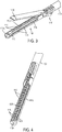
FIG. 1 is a perspective view of a surgical device configured to apply fasteners to tissue and including an end effector, the end effector being in a closed position; -
FIG. 2 is a perspective view of the end effector ofFIG. 1 in an open position; -
FIG. 3 is a perspective view of the end effector ofFIG. 2 with a cartridge removably coupled thereto; -
FIG. 4 is a perspective, partially cross-sectional view of the end effector and the cartridge ofFIG. 3 ; -
FIG. 5 is a perspective view of the cartridge ofFIG. 3 ; -
FIG. 6 is another perspective view of the cartridge ofFIG. 3 ; -
FIG. 7 is a perspective view of a sled of the cartridge ofFIG. 3 , the sled including a cutting element, and the cutting element being in a first position; -
FIG. 8 is a perspective view of the sled ofFIG. 7 with the cutting element in a second position that is different from the first position; -
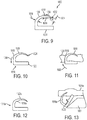
FIG. 9 is a side view of a fastener including an anti-rotation mechanism; -
FIG. 10 is a side view of another fastener including an anti-rotation mechanism; -
FIG. 11 is a side, partially transparent view of the fastener ofFIG. 10 deployed in tissue; -
FIG. 12 is a side view of yet another fastener including an anti-rotation mechanism; -
FIG. 13 is a side, partially transparent view of the fastener ofFIG. 12 being deployed in tissue; -
FIG. 14 is a side view of a fastener including first and second anti-rotation mechanisms; -
FIG. 15 is a side view of another fastener including an anti-rotation mechanism; -
FIG. 16 is a side, partially transparent view of the fastener ofFIG. 15 deployed in tissue; -
FIG. 17 is a perspective view of an embodiment of a fastener according to the invention including an anti-rotation mechanism; -
FIG. 18 is a perspective view of an embodiment of a plurality of interconnected deployed fasteners; -
FIG. 19 is a perspective view another embodiment of a fastener according to the invention including a first anti-rotation mechanism and a second anti-rotation mechanism, with the first anti-rotation mechanism coupled to an adjacent fastener; -
FIG. 20 is a perspective view of a cartridge and staples that can be deployed therefrom in opposite-facing longitudinal rows; -
FIG. 21 is a side, partially transparent view of the staples ofFIG. 20 that face in one direction being deployed from the cartridge with a drive beam engaged with a first sled translating distally through the cartridge; -
FIG. 22 is a side, partially transparent view of the first wedge sled ofFIG. 21 at a distal end of the cartridge and passing over a second sled; -
FIG. 23 is a side, partially transparent view of the drive beam engaged with the second sled ofFIG. 22 and disengaged from the first sled; -
FIG. 24 is a side, partially transparent view of the staples ofFIG. 23 facing in an opposite direction being deployed from the cartridge with the drive beam engaged with a second sled translating proximally through the cartridge; -
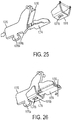
FIG. 25 is a perspective view of the drive beam and the first sled ofFIG. 24 coupled together and moving distally, and a perspective view of second sled not coupled to and positioned distal to the drive beam and the first sled; -
FIG. 26 is a perspective view of the drive beam and the first sled ofFIG. 22 coupled together and the first sled passing by the second sled; -
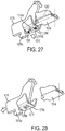
FIG. 27 is a perspective view of the drive beam and the second sled ofFIG. 23 coupled together and a perspective view of first sled not coupled to and positioned distal to the drive beam and the second sled; and -
FIG. 28 is a perspective view of the drive beam and the second sled ofFIG. 24 coupled together and moving proximally, and a perspective view of first sled not coupled to and positioned distal to the drive beam and the second sled. - Certain exemplary embodiments will now be described to provide an overall understanding of the principles of the structure, function, manufacture, and use of the devices and methods disclosed herein.
- Further, in the present disclosure, like-named components generally have similar features, and thus each feature of each like-named component is not necessarily fully elaborated upon. Additionally, to the extent that linear or circular dimensions are used in the description of the disclosed systems, devices, and methods, such dimensions are not intended to limit the types of shapes that can be used in conjunction with such systems, devices, and methods. A person skilled in the art will recognize that an equivalent to such linear and circular dimensions can easily be determined for any geometric shape. Sizes and shapes of the systems and devices, and the components thereof, can depend at least on the anatomy of the subject in which the systems and devices will be used, the size and shape of components with which the systems and devices will be used, and the methods and procedures in which the systems and devices will be used.
- It will be appreciated that the terms "proximal" and "distal" are used herein with reference to a user, such as a clinician, gripping a handle of an instrument. Other spatial terms such as "front" and "back" similarly correspond respectively to distal and proximal. It will be further appreciated that for convenience and clarity, spatial terms such as "vertical" and "horizontal" are used herein with respect to the drawings. However, surgical instruments are used in many orientations and positions, and these spatial terms are not intended to be limiting and absolute.
-
FIG. 1 illustrates asurgical device 1100 that is configured to apply staples to tissue. Thedevice 1100 includes a linear stapler configured to apply linear rows of staples. Other surgical devices that are configured to apply staples to tissue are described inU.S. Pat. No. 5,465,895 entitled "Surgical Stapler Instrument" filed February 3, 1994,U.S. Pat. No. 7,000,818 entitled "Surgical Stapling Instrument Having Separate Distinct Closing And Firing Systems" filed May 20, 2003,U.S. Pat. No. 7,669,746 entitled "Staple Cartridges For Forming Staples Having Differing Formed Staple Heights" filed on August 31, 2005, andU.S. Pat. Pub. No. 2014/0175146 entitled "Microcutter Stapling Apparatus Clamp And Deploy Mechanisms Systems And Methods" filed December 19, 2013. - Referring again to
FIG. 1 , thedevice 1100 includes aproximal handle portion 1102 having anelongate shaft 1104 extending distally therefrom. As also shown inFIG. 2 andFIG. 3 , theshaft 1104 has anend effector 1106 coupled to a distal end thereof. Theend effector 1106 is coupled to theshaft 1104 at a pivot joint 1108. A proximal end of theend effector 1106 is pivotally coupled to the joint 1108 at a distal end of theshaft 1104. Theend effector 1106 includes a tissue grasper having a pair of opposed first andsecond jaws handle portion 1102 is configured to be manipulated to effect the opening and closing of theopposed jaws jaws handle portion 1102 is configured to be manipulated to effect the firing of staples (not shown) from a one of thejaws jaws 1110a. The staple firing is independent of the opening and closing of thejaws - The
handle portion 1102 can have a variety of sizes, shapes, and configurations. As illustrated, Thehandle portion 1102 includes amain housing 1121, which houses a variety of elements therein and has some elements accessible outside thereof, such as a movable trigger 1122 and astationary handle 1124. The movable trigger 1122 is configured to be manually manipulated to move the movable trigger 1122 relative to thestationary handle 1124 so as to, e.g., effect closing of thejaws - The
shaft 1104 can have a variety of sizes, shapes, and configurations. For example, theshaft 1104 is rigid, e.g., made from a generally non-bendable material such as a metal (e.g., stainless steel, titanium, etc.) or a hard polymer. In other examples, theshaft 1104 can be configured to bend, such as being made from a generally flexible material, by including one or more articulation regions, etc. Theshaft 1104 can have any longitudinal length, although in an exemplary case it is long enough to allow thehandle portion 1102 to be manipulated outside a patient's body while theshaft 1104 extends through an opening in the body with theend effector 1106 disposed within a body cavity. In this way, theend effector 1106 can be easily manipulated when thedevice 1100 is in use during a surgical procedure. Theshaft 1104 can have any suitable diameter. For example, the shaft's diameter can be less than or equal to about 10 mm, e.g., less than or equal to about 7 mm, less than or equal to about 5 mm, etc., which allows for insertion of theshaft 1104 through an minimally invasive access device, e.g., a trocar, a cannula, a multiport access device, etc., such as during a laparoscopic surgical procedure. Theend effector 1106 coupled to the shaft's distal end can have a diameter equal to or less than the shaft's diameter, at least when thejaws - The
end effector 1106 can have a variety of sizes, shapes, and configurations. For example, theend effector 1106 is rigid. As shown inFIG. 2 andFIG. 3 , theend effector 1106 including the first andsecond jaws surgical device 1100. When thejaws second jaw 1110b is configured to remain stationary relative to theshaft 1104, and thefirst jaw 1110a is configured to move relative to theshaft 1104 and thesecond jaw 1110b by pivoting at the pivot joint 1108. - The
end effector 1106 is configured to releasably and replaceably seat acartridge 1112 therein, as shown inFIG. 3 and FIG. 4 . In this way, when the staples have been fired from thecartridge 1112, thecartridge 1112 can be removed from thesecond jaw 1110b and, optionally, replaced with another cartridge having another plurality of staples disposed therein.FIG. 2 shows theend effector 1106 without thecartridge 1112 seated therein. Theend effector 1106 is configured to receive thecartridge 1112 in thefirst jaw 1110a thereof, e.g., in a channel formed in thefirst jaw 1110a. Thefirst jaw 1110a can be configured to seat cartridges of different sizes, thereby facilitating versatility of thedevice 1100. - The
cartridge 1112 can have a variety of sizes, shapes, and configurations, as will be appreciated by a person skilled in the art. As shown inFIG. 4 ,FIG. 5, and FIG. 6 , thecartridge 1112 includes asled 1120 and has a plurality ofstaples 1116 disposed therein. Thesled 1120 is also illustrated inFIG. 7 and FIG. 8 . Thecartridge 1112 includes aplurality openings 1114 formed in atissue engaging surface 1118 thereof, as shown inFIG. 3 ,FIG. 5, and FIG. 6 . Thestaples 1116 disposed in thecartridge 1112 may be configured to be ejected from thecartridge 1112 through theopenings 1114, e.g., onestaple 1116 out of each opening 1114 (as illustrated), two staples out of eachopening 1114, etc. Theopenings 1114 define staple-receiving recesses of thecartridge 1112 in which thestaples 1116 are seated prior to being ejected from thecartridge 1112. - The
staples 1116 can have a variety of sizes, shapes, and configurations. Thestaples 1116 each have a D-shape and include a first leg that is substantially straight and a second leg that is curved. A person skilled in the art will appreciate that the first leg may not be precisely straight, e.g., due to manufacturing tolerances, but nevertheless be considered to be substantially straight. Each of thestaples 1116 is configured to be plastically deformable such that thestaples 1116 can each be configured to change shape, such as when thestaple 1116 is pressed against a tissue engaging surface (not shown) of thefirst jaw 1110a that faces thetissue engaging surface 1118 of thesecond jaw 1110b, while remaining a single unit, e.g., without either of the first and second legs breaking. A gap of space exists between a terminal end of the first leg and a terminal end of the second leg. In other words, the "D" shape has a gap therein. The gap of space facilitates plastic deformation of thestaple 1116. - The
staples 1116 are each frangibly attached to acarrier 1126, also referred to herein as a "carrier strip," disposed within thecartridge 1112. Thestaples 1116 can be frangibly attached to thecarrier 1126 by, e.g., being stamped together with thecarrier 1126 such that thestaples 1116 and thecarrier 1126 forms a single piece. Thestaples 1116 can each be configured to detach from thecarrier 1126 when fired from thecartridge 1112. Some or all of thestaples 1116 can be frangibly attached to another element, such as another element disposed within thecartridge 1112, an inner surface of thecartridge 1112, the tissue-engagingsurface 1118 of thecartridge 1112, etc. Thecarrier 1126 can be fixedly attached to an upper surface of one ormore rails 1128 defined by thecartridge 1112. Thecarrier 1126 is configured to remain stationary relative to thecartridge 1112. - As shown in
FIG. 3 ,FIG. 5, and FIG. 6 , thecartridge 1112 has alongitudinal slot 1130 formed therein. Thelongitudinal slot 1130 extends along a substantially flatcentral portion 1118f of the tissue-engagingsurface 1118. Theslot 1130 is configured to have a cutting element such as a knife (not shown) extend therethrough so as to cut tissue engaged by the tissue-engagingsurface 1118, as discussed further below. Theopenings 1114 can be formed inangled portions 1118a of the tissue-engagingsurface 1118 on both sides of theslot 1130, as shown inFIG. 3 ,FIG. 5, and FIG. 6 . In some cases, the tissue-engagingsurface 1118 is substantially flat, e.g., not have angled portions, while in other cases, the tissue-engagingsurface 1118 can be angled, e.g., not have any substantially flat portions. - As shown in
FIG. 5 and FIG. 6 , thecartridge 1112 includes a gap-setting feature 1142 configured to set of gap of space between the first andsecond jaws jaws cartridge 1112 is seated in thesecond jaw 1110b. In this way, the gap-setting feature 1142 defines a minimum distance between the facing tissue-engaging surfaces of the first andsecond jaws setting feature 1142 can have a variety of sizes, shapes, and configurations. The gap-setting feature 1142 includes an indentation inward toward a lateral center of thecartridge 1112, where a portion of a lateral edge of thecartridge 1112 immediately proximal to the gap-setting feature 1142 is located laterally inward relative to a portion of a lateral edge of thecartridge 1112 located immediately distal to the gap-setting feature 1142. - The
sled 1120 of thecartridge 1112 can have a variety of sizes, shapes, and configurations. Thesled 1120 is configured to translate longitudinally along thecartridge 1112 to cause deployment of thestaples 1116 therefrom and to cause tissue engaged by theend effector 1106 to be cut with the cutting element extending through theslot 1130. Thestaples 1116 are arranged longitudinally in thecartridge 1112, as shown inFIG. 4 , and thesled 1120 is configured to sequentially engage the longitudinally arrangedstaples 1116 as thesled 1120 translates longitudinally. As illustrated inFIG. 7 and FIG. 8 , thesled 1120 includes a plurality ofwedges 1136 and includes acutting element 1134, which as illustrated includes a knife with ablade 1132. Thesled 1120 includes fourwedges 1136 but thesled 1120 can include any other number ofwedges 1136 as appropriate for the arrangement of thestaples 1116 in thecartridge 1112. Each of thewedges 1136 has a shape configured to cause thestaples 1116 contacted by thatwedge 1136 to move upward toward thesecond jaw 1110b through theopenings 1114 and deform against thesecond jaw 1110b. As shown inFIG. 6 , thecartridge 1112 includes a plurality oflongitudinal slots 1150 formed therein, each of theslots 1150 being configured to slidably receive one of thewedges 1136 therein. Theslots 1150 facilitate consistent, straight movement of thewedges 1136 through thecartridge 1112 to help ensure proper engagement of thewedges 1136 with thestaples 1116. - Each of the
wedges 1136 is attached to abase 1138 of thesled 1120 and is in a fixed position relative thereto. Thebase 1138 has aguide element 1139 extending generally downward therefrom. Theguide element 1139 is configured to slide within a channel formed in thecartridge 1112 that includes thesled 1120. Thecutting element 1134 can also be attached to thebase 1138, but thecutting element 1134 can insteadbe configured to move relative to thebase 1138. Thecutting element 1134 can be substantially laterally centered in thebase 1138, which facilitates substantially central positioning of thecutting element 1134 relative to tissue engaged by theend effector 1106. - The
cutting element 1134 is movable relative to the remainder of thesled 1120 between a first position, shown inFIG. 7 , and a second position, shown inFIG. 6 andFIG. 8 . The first position is an initial position of thecutting element 1134. In the first position, also referred to herein as a "stowed position," theblade 1132 is generally obscured, e.g., oriented generally downward as shown inFIG. 4 ,FIG. 5 ,FIG. 6 , andFIG. 7 , which helps prevent theblade 1132 from inadvertent cutting, such as accidentally cutting a user of thedevice 1100 during seating of thecartridge 1120 within theend effector 1104 and/or premature cutting of tissue engaged by theend effector 1104. Thebase 1138 has acavity 1144 formed therein, as shown inFIG. 6 , which is configured to seat thecutting element 1134 at least partially therein when thecutting element 1134 is in the first position. In the second position, also referred to herein as an "upright position," theblade 1132 is generally unobscured and facing distally as shown inFIG. 6 andFIG. 8 , which allows theblade 1132 to extend through theslot 1130 and cut tissue engaged by theend effector 1106. - The
sled 1120 includes apivot member 1140 configured to facilitate movement of thecutting element 1134 relative to the remainder of thesled 1120. Thepivot member 1140 can have a variety of sizes, shapes, and configurations. Thepivot member 1140 is attached to thecutting element 1134 such that engagement of thepivot member 1140 causes thecutting element 1134 to pivot about a pivot point so as to move relative to the remainder of the sled. As illustrated thepivot member 1140 includes two separate pins extending laterally from opposite sides of thecutting element 1134. In other case, thepivot member 1140 can include a single pin extending through thecutting element 1134 to extend laterally from opposite sides therefrom, a single pin extending laterally from one side of thecutting element 1134, etc. At the pivot point, thesled 1120 includes apivot axle 1146 extending laterally from thecutting element 1134, and includes anaxle cavity 1148 formed in thebase 1138 and configured to receive thepivot axle 1146 therein. - The surgical devices described herein can be used in a variety of surgical procedures. The procedure can be a minimally invasive procedure in which the surgical device is advanced into a body of a patient through a relatively small opening in the patient. In a minimally invasive surgical procedure, one or more introducer devices (not shown), e.g., a cannula, a trocar, etc., may be advanced through an opening in the patient to provide access to a surgical site. A person skilled in the art will appreciate that one or more viewing devices, e.g., a scoping device such as an endoscope, can be advanced into the body through the incision or through another opening, e.g., another incision or a natural orifice, to provide visualization of the surgical site from outside the body. As will be appreciated by a person skilled in the art, the surgical device can be advanced into the patient's body in a variety of ways, such as by being inserted transorally therein, inserted through an introducer device, inserted through a scoping device, inserted directly through an incision, etc. Although the following example of use of a surgical device in a surgical procedure is described with respect to the
device 1100 ofFIG. 1 , any of the surgical devices described herein can be similarly used. - The surgical devices described herein can have any one or more variations to facilitate effective use of the device. Examples of such variations are described further below.
- In some cases, a surgical device such as the above-mentioned
surgical device 1100 is configured to stabilize fasteners post-deployment. In general, the fasteners can be configured to resist counter rotation after being deployed. Fasteners can have a tendency to shift position relative to tissue that the fasteners are securing. The position shifting can be caused by any one or more factors, such as the type of the tissue, the thickness of the tissue, the shape of the fasteners (e.g., a curved shape), and the strength of any bias urging the fastener into a certain position or configuration. The position shifting can take the form of counter rotation, in which the fastener rotates in a direction opposite to the direction in which the fastener was deployed into the tissue. This counter rotation can reduce the fastener's effectiveness in fastening the tissue because the fastener is "slipping" out of the tissue and/or reducing its hold on the tissue as a result of the counter rotation. The adverse effects of counter rotations can be exacerbated when, as in typical surgical procedures that use fasteners, a plurality of fasteners, all of which may counter rotate to varying degrees, are deployed in tissue. The adverse effects of counter rotations can be exacerbated when tissue is relatively thick such that staples may not close to a sufficient extent when deployed in the tissue. Fasteners being configured to resist counter rotation helps keep the staples secured in tissue into which the staples have been deployed, thereby helping to keep the tissue securely fastened and/or facilitating effective treatment of the tissue. - A fastener can be configured to resist counter rotation in a variety of ways. As described below, staples are used as examples of fasteners, but as will be appreciated by a person skilled in the art, other types of fasteners can be similarly configured and used.
- A staple can include one or more anti-rotation mechanisms configured to resist counter rotation of the staple when the staple is deployed in tissue.
FIG. 9 illustrates a staple 1000 that includes one or moreanti-rotation mechanisms 1008 configured to resist counter rotation. Thestaple 1000 is generally configured like the previously describedstaples 1116 and has a D-shape with apointed tip 1002, afirst leg 1004 that is substantially straight and asecond leg 1006 that is curved. Thepointed tip 1002 can be a terminal end of thesecond leg 1006, as illustrated. - The
staple 1000 includes one or moreanti-rotation mechanisms 1008, which as illustrated includes abarb 1008. This illustrated case includes only onebarb 1008, but thestaple 1000 can include one ormore barbs 1008 that are substantially identical to one another. Thebarb 1008 can be located in a variety of locations on thestaple 1000. The one ormore barbs 1008 are formed on an inner-facing surface of thesecond leg 1006 at thepointed tip 1002. Thebarbs 1008 are oriented in afirst direction 1010 that is opposite to asecond direction 1012 in which the pointedtip 1002 points. Thesecond direction 1012 is the direction in which thestaple 1000 is deployed into tissue, with the pointedtip 1002 leading the staple 1000 into the tissue. When thestaple 1000 is deployed in the tissue, thebarb 1008 thus prevents counter rotation of the staple 1000 therein, thereby helping to retain the staple securely within the tissue. - The
barb 1008 can have a variety of sizes. For example, thebarb 1008 has amaximum diameter 1014 is less than or substantially equal to amaximum diameter 1016 of thesecond leg 1006. In this way, the hole created by thebarb 1008 when thebarb 1008 penetrates into tissue can be smaller than or substantially equal in size to the hole created by thesecond leg 1006 when thesecond leg 1006 passes through the tissue, thereby helping to reducing any potential hemostasis issues that may arise from thebarb 1008. Thesecond leg 1006 can be tapered toward the pointedtip 1002 such that themaximum diameter 1016 of thesecond leg 1006 is adjacent a terminal end thereof that is opposite the pointedtip 1002. -
FIG. 10 and FIG. 11 illustrate anotherstaple 1016 that includes one or moreanti-rotation mechanisms 1018 configured to resist counter rotation. Thestaple 1016 and the one or moreanti-rotation mechanisms 1018, e.g., one ormore barbs 1018, can be generally configured and used similarly to thestaple 1000 and the one ormore barbs 1008, respectively, ofFIG. 9 . The one ormore barbs 1018, however, are formed in an intermediate portion of the staple'ssecond leg 1020 between proximal and distal ends thereof, and the one ormore barbs 1018 are formed on an outer-facing surface of asecond leg 1020 of the staple 1016 that includes a pointedtip 1024 of thestaple 1016 and that is connected to afirst leg 1022 of thestaple 1016. -
FIG. 11 illustrates the staple 1016 as deployed in atissue 1026. Thestaple 1016 is deployed into thetissue 1026, e.g., fired from a cartridge such as the above-mentionedcartridge 1112, in afirst direction 1028. The one ormore barbs 1018 are oriented in asecond direction 1030 that is opposite to thefirst direction 1028, thereby helping to secure the staple 1016 to thetissue 1026 and helping to prevent counter rotation of thestaple 1016 within thetissue 1026. The one ormore barbs 1018 are formed in the second leg's intermediate portion at a location substantially where thestaple 1016 exits thetissue 1026, as illustrated. An exterior surface of thetissue 1026 cooperates with the one ormore barbs 1018 at such a location to help prevent counter rotation of thestaple 1018, e.g., help prevent the staple 1016 from rotating in thesecond direction 1030 after being deployed in thetissue 1026. - In another example, the one or more barbs are formed on an inner-facing surface of the second leg in addition to or in alternative to the one or more barbs formed on the outer-facing surface of the second leg.
FIG. 12 illustrates such astaple 1016a with one ormore barbs 1018a formed on an inner-facing surface of asecond leg 1020a of the staple 1016a. The staple 1016a and the one or moreanti-rotation mechanisms 1018a can be generally configured and used similarly to thestaple 1000 and the one ormore barbs 1008, respectively, ofFIG. 9. FIG. 13 illustrates the staple 1016a being deployed in atissue 1026a by being pushed by awedge 1027 of a sled so as to rotate the staple 1016a in a direction of anarrow 1029.FIG. 14 illustrates another staple 1016b with one ormore barbs 1018b formed on an inner-facing surface of asecond leg 1020b of the staple 1016b. Thestaple 1016b is like the staple 1016a ofFIG. 12 except the staple 1016b ofFIG. 14 includes at least onesecond anti-rotation mechanism 1017 on an outer-facing surface of thesecond leg 1020b. The at least onesecond anti-rotation mechanism 1017 includes a plurality of spikes extending outward from the outer-facing surface of thesecond leg 1020b. -
FIG. 15 and FIG. 16 illustrate anotherstaple 1032 that includes one or moreanti-rotation mechanisms 1034 configured to resist counter rotation. Thestaple 1032 and the one or moreanti-rotation mechanisms 1034, e.g., one ormore barbs 1034, can be generally configured and used similarly to thestaple 1000 and the one ormore barbs 1008, respectively, ofFIG. 9 . The one ormore barbs 1034, however, are formed on an outer-facing surface of asecond leg 1036 of the staple 1032 closer to a first leg 1037 of the staple 1032 than inFIG. 9 , and are formed adjacent a terminal end of thesecond leg 1036 that is opposite to a terminal end thereof that includes a pointedtip 1038. In another example, the one or more barbs can be formed on an inner-facing surface of thesecond leg 1036 in addition to or in alternative to the one ormore barbs 1034 formed on the outer-facing surface of thesecond leg 1036. -
FIG. 16 illustrates the staple 1032 deployed in atissue 1040. The one ormore barbs 1034 of the staple 1032 can be oriented similar to the one ormore barbs 1026 ofFIG. 10 and FIG. 12 so as to be oriented in a direction that is opposite to the direction in which thestaple 1032 was deployed into thetissue 1040. The one ormore barbs 1034 are formed on thesecond leg 1036 at a location disposed within thetissue 1040 when thestaple 1032 is within thetissue 1040, as illustrated. Thetissue 1040 can thus completely surround the one ormore barbs 1034 so as to help the one ormore barbs 1034 prevent counter rotation. - In embodiments of the invention, an anti-rotation mechanism of a first staple is configured to engage a second staple deployed adjacently thereto in tissue. The anti-rotation mechanism can be configured to help prevent counter rotation of the first and second staples. In an exemplary embodiment, an anti-rotation mechanism of a staple configured to engage an adjacent staple is in the form of a coupling element configured to receive a pointed tip of the adjacent staple when both of the staples are deployed in tissue.
-
FIG. 17 illustrates one embodiment of a staple 1042 that includes ananti-rotation mechanism 1044 in the form of a coupling element configured to engage an adjacently deployed staple. The staple 1042 in this illustrated embodiment is generally configured and used like the previously describedstaples 1116 and has a D-shape with apointed tip 1046, afirst leg 1048 that is substantially straight and asecond leg 1050 that is curved. Thepointed tip 1046 is a first terminal end of thesecond leg 1050, as in this illustrated embodiment. Theanti-rotation mechanism 1044 is formed on an outer-facing surface of thestaple 1042 and located at a junction of the first andsecond legs anti-rotation mechanism 1044 includes a ring or hoop configured to receive a pointed tip of an adjacent staple therein. The pointed tip extends partially or all the way through ahole 1052 defined by theanti-rotation mechanism 1044. Theanti-rotation mechanism 1044 having the adjacent staple's tip at least partially captured by theanti-rotation mechanism 1044 helps to prevent counter rotation of the staple 1042 as well as the adjacent staple engaged by thestaple 1042. Because thestaple 1042 can be rotated to be deployed in tissue and can be one of a plurality of staples deployed in a longitudinal row, as discussed herein, the staple'stip 1046 is able to rotate into a previously deployed staple's anti-rotation mechanism. In this way, staples deployed in the longitudinal row can all be interconnected with one another via the anti-rotation mechanisms, thereby helping to stabilize the entire row of staples in tissue. -
FIG. 18 illustrates a plurality ofstaples staple 1042 ofFIG. 17 , having been deployed such that a pointed tip of a staple is captured as it rotates by an anti-rotation mechanism of the one of the staples having been deployed immediately prior thereto. In other words, apointed tip 1046b of the staple 1042b deployed second has been captured by ananti-rotation mechanism 1044a of thestaple 1042a deployed first, and apointed tip 1046c of the staple 1042c deployed third has been captured by ananti-rotation mechanism 1044b of the staple 1042b deployed second. As shown in this illustrated embodiment, the pointedtip 1046a of thefirst staple 1042a is not coupled to an anti-rotation mechanism, and the anti-rotation mechanism of the last one of the deployedstaples 1042c is not coupled to another staple. Only threestaples -
FIG. 19 illustrates another embodiment of a staple 1054 that includes ananti-rotation mechanism 1056 in the form of a coupling element configured to engage an adjacently deployed staple. The staple 1054 in this illustrated embodiment is generally configured and used like thestaple 1042 ofFIG. 17 except that thestaple 1054 includes asecond anti-rotation mechanism 1058. Thesecond anti-rotation mechanism 1058 in this illustrated embodiment is apointed tip 1060 of the staple 1056 having a barb similar to thebarb 1008 ofFIG. 9 . Thesecond anti-rotation mechanism 1058 in the form of a barb helps hold the staple 1054 in tissue and helps prevent the pointedtip 1060 from de-coupling from an adjacent staple's anti-rotation mechanism, e.g., from moving out of a hole of a ring or loop once advanced therein.FIG. 19 also shows anadjacent staple 1054a (partially illustrated), which is generally configured and used similarly to thestaple 1054, with itspointed tip 1060a andsecond anti-rotation mechanism 1058a engaged by theanti-rotation mechanism 1056 of thestaple 1054. - The orientation of a fastener relative to the orientation of one or more fasteners deployed adjacent thereto can be configured to help prevent counter rotation. For example, fasteners in one longitudinal row all face in a first direction, e.g., proximally, and fasteners in a longitudinal row adjacent thereto all face in the opposite direction, e.g., distally. In this way, forces exerted on tissue in which the fasteners facing opposite directions are deployed can help hold the fasteners in the tissue.
-
FIG. 20 illustrates acartridge 1062 that hasstaples 1066 in adjacent longitudinal rows facing in opposite directions. Thestaples 1066 are shown deployed out of thecartridge 1062 for ease of explanation. Thecartridge 1062 as illustrated has first, second, third, and fourthlongitudinal rows staples 1066. Thestaples 1066 in the first andfourth rows 1064a, 1064d face in a first direction, e.g., a distal direction, when deployed, and thestaples 1066 in the second andthird rows 1064b, 1064c face in a second, opposite direction, e.g., a proximal direction, when deployed. In this way, when thestaples 1062 are in tissue, the adjacent first and second rows 1064a, 1064b ofstaples 1066 face in opposite directions, and the adjacent third andfourth rows staples 1066 face in opposite directions. A cutting element (not shown) extends through alongitudinal slot 1072 in thecartridge 1062 and cuts tissue between the second andthird rows 1064b, 1064c as discussed herein such that the second andthird rows 1064b,1064c having staples 1066 facing the same direction generally will not affect counter rotation. - As discussed herein, the
staples 1066 can be deployed from thecartridge 1062 by rotating out ofopenings 1068 formed in the cartridge's tissue-engagingsurface 1070. Typically, all staples in a cartridge are deployed as a sled moves longitudinally through the cartridge, e.g., as the sled translates distally. However, thestaples 1066 facing in opposite directions can be deployed in two passes of a sled through thecartridge 1062, one pass in which the sled translates distally to deploy thestaples 1066 facing in one direction and another pass in which the sled translates proximally to deploy the staples facing the opposite direction. -
FIG. 21 ,FIG. 22, FIG. 23, and FIG. 24 illustrate deploying thestaples 1066 that face in opposite directions using afirst sled 1074, a drive beam 1076 (also referred to herein as a "drive rod" and an "I-beam"), and asecond sled 1078, which are also shown inFIG. 25, FIG. 26 ,FIG. 27, and FIG. 28 . Although as illustrated, deployment of thestaples 1066 disposed in thecartridge 1062, other staples disposed in other cartridges facing the opposite direction can be similarly deployed. The relative positions of the first sled,drive beam 1076, andsecond sled 1078 inFIG. 25, FIG. 26 ,FIG. 27, and FIG. 28 correspond respectively to their positions inFIG. 21 ,FIG. 22, FIG. 23, and FIG. 24 . Thefirst sled 1074 can be generally configured and used similarly to the previously describedsled 1120. Thefirst sled 1074 includes acutting element 1080, which includes a knife as illustrated. Thecutting element 1080 pivots between a stowed position in which the cutting element's blade 1082 is generally obscured, as shown inFIG. 22, FIG. 23, FIG. 24 ,FIG. 26 ,FIG. 27, and FIG. 28 , and an upright position in which thecutting element 1080 extends through theslot 1072 such that the blade 1082 can cut tissue, as shown inFIG. 21 andFIG. 25 . - As shown in
FIG. 21 andFIG. 25 , thesecond sled 1078 can be parked in an initial position near a distal end of thecartridge 1062. Thedrive beam 1076 can be advanced distally, e.g., by manipulating a handle of a surgical device that includes thecartridge 1062 seated in an end effector thereof, so as to cause thecutting element 1080 to move from the stowed position to the upright position and so as to push thefirst sled 1074 distally. Thedrive bean 1076 includes aguide member 1076a configured to slide within a corresponding guide track (not shown) formed in thecartridge 1062, which helps thedrive beam 1076 translate straight and smoothly within thecartridge 1062. The distal movement of thefirst sled 1074 causes the second andthird rows 1064b, 1064c ofstaples 1066 to be deployed. - After deploying the
staples 1066 in the second andthird rows 1064b, 1064c, the distally advancingfirst sled 1074 advances distally beyond the parkedsecond sled 1078, as shown inFIG. 22 andFIG. 26 , and thedrive rod 1076 engages the parkedsecond sled 1078, as shown inFIG. 23 andFIG. 27 . Thedrive rod 1076 can engage thesecond sled 1078 in a variety of ways. Thedrive rod 1076 includes aprotrusion 1076b extending therefrom configured to engage acorresponding opening 1078b formed in thesecond sled 1078. Thefirst sled 1076 being advanced to its distal-most position relative to thecartridge 1062 causes aspring 1084, shown inFIG. 27 , to be released. Thespring 1084 is coupled to thesecond sled 1078 and biased upward such that release of thespring 1084 causes thesecond sled 1078 to move upward, thereby allowing theprotrusion 1076b to engage theopening 1078 as shown inFIG. 23 andFIG. 27 . Thedrive rod 1076 can be advanced proximally, e.g., by manipulating the handle of the surgical device, so as to cause thesecond sled 1078 engaged with thedrive rod 1076 to move from the parked position and be advanced proximally with thedrive rod 1076 due to the engagement of theprotrusion 1076b and theopening 1078b. As shown inFIG. 25 andFIG. 28 , the proximal movement of thesecond sled 1078 causes the first andfourth rows 1064a, 1064d ofstaples 1066 to be deployed. Thefirst sled 1074 is parked near the distal end of thecartridge 1062 during the drive beam's and second sled's proximal movement, as also shown inFIG. 24 andFIG. 28 . The tissue is thus cut before all of thestaples 1066 have been deployed since the tissue is cut by thecutting element 1080 during firing of thestaples 1066 in the second andthird rows 1064b, 1064c and prior to firing of any of the staples in the first andfourth rows 1064a, 1064d. - Two-pass deployment of the
staples 1066 in which a first quantity of thestaples 1066 are deployed in one pass, e.g., a distal pass of thedrive beam 1076, and a second, remaining quantity of thestaples 1066 are deployed in a second pass, e.g., a proximal pass of thedrive beam 1076, reduces the force needed to fire thestaples 1066. A first force is required to deploy thestaples 1066 in the first pass, and a second force is required to deploy thestaples 1066 in the second pass. In this way, instead of requiring the sum of the first and second forces to deploy all of thestaples 1066, two smaller forces can be applied to deploy all of the staples. These reduced forces for firing can make firing of staples much easier in devices having relatively small diameters, such as those used in minimally invasive surgical procedures. For example, it can be difficult to generate a force required to deploy staples from an end effector of a 5 mm device, so effectively dividing the force required in half by having two passes makes the device easier to use and/or more effective in deploying staples properly. - In another examples of deploying staples from a cartridge in which some of the staples are disposed therein facing one direction and the remainder of the staples are disposed therein facing another, opposite direction, the sled is configured to advance distally through the cartridge so as to cause deployment of all of the staples. In other words, the sled's distal movement causes deployment of staples facing in opposed directions. Such a sled may include sides that extend upward and downward on left and right sides thereof so as to allow movement of the sled in one direction to cause deployment of staples facing in opposite directions.
- A person skilled in the art will appreciate that the present invention has application in conventional minimally-invasive and open surgical instrumentation as well as application in robotic-assisted surgery.
- The devices disclosed herein can also be designed to be disposed of after a single use, or they can be designed to be used multiple times. In either case, however, the device can be reconditioned for reuse after at least one use. Reconditioning includes any combination of the steps of disassembly of the device, followed by cleaning or replacement of particular pieces and subsequent reassembly. In particular, the device can be disassembled, and any number of the particular pieces or parts of the device can be selectively replaced or removed in any combination. Upon cleaning and/or replacement of particular parts, the device can be reassembled for subsequent use either at a reconditioning facility, or by a surgical team immediately prior to a surgical procedure. Those skilled in the art will appreciate that reconditioning of a device can utilize a variety of techniques for disassembly, cleaning/replacement, and reassembly. Use of such techniques, and the resulting reconditioned device, are all within the scope of the present application.
- One skilled in the art will appreciate further features and advantages of the invention based on the above description. Accordingly, the invention is not to be limited by what has been particularly shown and described, except as indicated by the appended claims.
Claims (7)
- A surgical fastening device (1100), comprising:an elongate shaft (1104) having an end effector (1106) coupled to a distal end thereof, the end effector includingfirst and second opposed jaws (1110a, 1110b) coupled to one another and configured to engage tissue therebetween, anda staple cartridge (1112) disposed within the first jaw, the staple cartridge including a plurality of D-shaped, plastically deformable staples (1042; 1054), each staple being configured to rotate in a first direction into tissue engaged between the first and second jaws, and each staple having an anti-rotation mechanism configured to prevent rotation in a second direction opposite to the first direction when the staples are deployed in tissue;characterized in that the anti-rotation mechanism comprises a coupling element (1044; 1056) formed on each staple and configured to receive a tip (1046; 1060) of an adjacent staple when deployed such that counter-rotation of the staples is prevented.
- The device of claim 1, wherein each D-shaped staple includes a first leg (1048) that is substantially straight, and a second leg (1050) that is curved.
- The device of claim 2, wherein the anti-rotation mechanism on each staple comprises a hoop (1044; 1056) formed adjacent to an intersection between the first and second legs and configured to receive a tip (1046; 1060) of the second leg (1050) of an adjacent staple when the staples are deployed in tissue.
- The device of claim 3, wherein the anti-rotation mechanism on each staple comprises a barb formed on a tip (1060) of the second leg (1050) and adapted to prevent the tip (1060) from de-coupling from the hoop of an adjacent staple.
- The device of claim 4, wherein the barb is formed on the inner surface of the second leg.
- The device of any preceding claim, wherein the plurality of staples are frangibly attached to a carrier (1126).
- The device of any preceding claim, wherein the plurality of staples are arranged in longitudinal rows (1064a- 1064d).
Priority Applications (2)
| Application Number | Priority Date | Filing Date | Title |
|---|---|---|---|
| PL15183383T PL3000407T3 (en) | 2014-09-02 | 2015-09-01 | Devices and methods for stabilizing fasteners post-deployment |
| EP18173568.9A EP3403593B1 (en) | 2014-09-02 | 2015-09-01 | Devices for stabilizing fasteners post-deployment |
Applications Claiming Priority (1)
| Application Number | Priority Date | Filing Date | Title |
|---|---|---|---|
| US14/474,653 US9907554B2 (en) | 2014-09-02 | 2014-09-02 | Devices and methods for stabilizing fasteners post-deployment |
Related Child Applications (1)
| Application Number | Title | Priority Date | Filing Date |
|---|---|---|---|
| EP18173568.9A Division EP3403593B1 (en) | 2014-09-02 | 2015-09-01 | Devices for stabilizing fasteners post-deployment |
Publications (3)
| Publication Number | Publication Date |
|---|---|
| EP3000407A2 EP3000407A2 (en) | 2016-03-30 |
| EP3000407A3 EP3000407A3 (en) | 2016-07-13 |
| EP3000407B1 true EP3000407B1 (en) | 2018-05-23 |
Family
ID=54014740
Family Applications (2)
| Application Number | Title | Priority Date | Filing Date |
|---|---|---|---|
| EP18173568.9A Active EP3403593B1 (en) | 2014-09-02 | 2015-09-01 | Devices for stabilizing fasteners post-deployment |
| EP15183383.7A Active EP3000407B1 (en) | 2014-09-02 | 2015-09-01 | Devices and methods for stabilizing fasteners post-deployment |
Family Applications Before (1)
| Application Number | Title | Priority Date | Filing Date |
|---|---|---|---|
| EP18173568.9A Active EP3403593B1 (en) | 2014-09-02 | 2015-09-01 | Devices for stabilizing fasteners post-deployment |
Country Status (3)
| Country | Link |
|---|---|
| US (1) | US9907554B2 (en) |
| EP (2) | EP3403593B1 (en) |
| PL (1) | PL3000407T3 (en) |
Families Citing this family (8)
| Publication number | Priority date | Publication date | Assignee | Title |
|---|---|---|---|---|
| US9655613B2 (en) * | 2013-03-14 | 2017-05-23 | Dextera Surgical Inc. | Beltless staple chain for cartridge and cartridgeless surgical staplers |
| US9788835B2 (en) | 2014-09-02 | 2017-10-17 | Ethicon Llc | Devices and methods for facilitating ejection of surgical fasteners from cartridges |
| JP6803395B2 (en) * | 2016-11-18 | 2020-12-23 | オリンパス株式会社 | Medical stapler system |
| EP3391829A1 (en) * | 2017-04-21 | 2018-10-24 | Gothenburg Medtech Innovations AB | Wound closure device |
| US11812956B2 (en) * | 2021-05-18 | 2023-11-14 | Covidien Lp | Dual firing radial stapling device |
| US20230107231A1 (en) * | 2021-09-27 | 2023-04-06 | Cilag Gmbh International | Overlapping staple pattern for surgical stapler |
| CN217118490U (en) * | 2021-12-17 | 2022-08-05 | 天臣国际医疗科技股份有限公司 | Nail bin assembly and medical anastomat |
| US20230301675A1 (en) * | 2022-03-25 | 2023-09-28 | Cilag Gmbh International | Surgical stapler features for stapling variable thickness tissue |
Family Cites Families (39)
| Publication number | Priority date | Publication date | Assignee | Title |
|---|---|---|---|---|
| US5465895A (en) | 1994-02-03 | 1995-11-14 | Ethicon Endo-Surgery, Inc. | Surgical stapler instrument |
| US5976159A (en) * | 1995-02-24 | 1999-11-02 | Heartport, Inc. | Surgical clips and methods for tissue approximation |
| US5725536A (en) | 1996-02-20 | 1998-03-10 | Richard-Allen Medical Industries, Inc. | Articulated surgical instrument with improved articulation control mechanism |
| US7285131B1 (en) | 1999-07-28 | 2007-10-23 | Cardica, Inc. | System for performing anastomosis |
| US7850703B2 (en) * | 1999-07-28 | 2010-12-14 | Cardica, Inc. | System for performing anastomosis |
| US6755338B2 (en) | 2001-08-29 | 2004-06-29 | Cerebral Vascular Applications, Inc. | Medical instrument |
| US6978921B2 (en) | 2003-05-20 | 2005-12-27 | Ethicon Endo-Surgery, Inc. | Surgical stapling instrument incorporating an E-beam firing mechanism |
| US7914543B2 (en) | 2003-10-14 | 2011-03-29 | Satiety, Inc. | Single fold device for tissue fixation |
| US7641671B2 (en) | 2004-11-22 | 2010-01-05 | Design Standards Corporation | Closing assemblies for clamping device |
| US7678121B1 (en) | 2004-12-23 | 2010-03-16 | Cardica, Inc. | Surgical stapling tool |
| US7669746B2 (en) | 2005-08-31 | 2010-03-02 | Ethicon Endo-Surgery, Inc. | Staple cartridges for forming staples having differing formed staple heights |
| US8123795B1 (en) | 2005-10-03 | 2012-02-28 | Cardica, Inc. | System for attaching an abdominal aortic stent or the like |
| US20080078802A1 (en) * | 2006-09-29 | 2008-04-03 | Hess Christopher J | Surgical staples and stapling instruments |
| US7473258B2 (en) | 2007-03-08 | 2009-01-06 | Cardica, Inc. | Surgical stapler |
| US7533790B1 (en) | 2007-03-08 | 2009-05-19 | Cardica, Inc. | Surgical stapler |
| US7988026B2 (en) | 2007-09-06 | 2011-08-02 | Cardica, Inc. | Endocutter with staple feed |
| US8070036B1 (en) | 2007-09-06 | 2011-12-06 | Cardica, Inc | True multi-fire surgical stapler configured to fire staples of different sizes |
| US8403956B1 (en) | 2007-09-06 | 2013-03-26 | Cardica, Inc. | Multiple-use surgical stapler |
| US8356740B1 (en) | 2009-03-09 | 2013-01-22 | Cardica, Inc. | Controlling compression applied to tissue by surgical tool |
| US7918376B1 (en) | 2009-03-09 | 2011-04-05 | Cardica, Inc. | Articulated surgical instrument |
| US8317071B1 (en) | 2009-03-09 | 2012-11-27 | Cardica, Inc. | Endocutter with auto-feed buttress |
| WO2010114635A2 (en) * | 2009-04-03 | 2010-10-07 | Romans Matthew L | Absorbable surgical staple |
| US8317072B1 (en) | 2009-05-03 | 2012-11-27 | Cardica, Inc. | Feeder belt for true multi-fire surgical stapler |
| US8631992B1 (en) * | 2009-05-03 | 2014-01-21 | Cardica, Inc. | Feeder belt with padded staples for true multi-fire surgical stapler |
| US8070034B1 (en) | 2009-05-29 | 2011-12-06 | Cardica, Inc. | Surgical stapler with angled staple bays |
| US8056789B1 (en) | 2009-06-03 | 2011-11-15 | Cardica, Inc. | Staple and feeder belt configurations for surgical stapler |
| US8087562B1 (en) | 2009-06-22 | 2012-01-03 | Cardica, Inc. | Anvil for surgical instrument |
| US8701960B1 (en) | 2009-06-22 | 2014-04-22 | Cardica, Inc. | Surgical stapler with reduced clamp gap for insertion |
| US8261958B1 (en) | 2010-01-06 | 2012-09-11 | Cardica, Inc. | Stapler cartridge with staples frangibly affixed thereto |
| US8672209B2 (en) | 2010-02-25 | 2014-03-18 | Design Standards Corporation | Laproscopic stapler |
| US8662369B1 (en) * | 2010-05-27 | 2014-03-04 | Cardica, Inc. | Barbed surgical staple |
| US8439246B1 (en) | 2010-07-20 | 2013-05-14 | Cardica, Inc. | Surgical stapler with cartridge-adjustable clamp gap |
| US9173978B2 (en) * | 2010-09-22 | 2015-11-03 | Ethicon, Inc. | Bioabsorbable polymeric compositions, processing methods, and medical devices therefrom |
| US8636189B1 (en) | 2011-04-19 | 2014-01-28 | Cardica, Inc. | Active wedge for surgical stapler |
| US20130277410A1 (en) | 2012-04-18 | 2013-10-24 | Cardica, Inc. | Safety lockout for surgical stapler |
| US9566065B2 (en) | 2012-12-21 | 2017-02-14 | Cardica, Inc. | Apparatus and methods for surgical stapler clamping and deployment |
| US9867613B2 (en) | 2013-12-19 | 2018-01-16 | Covidien Lp | Surgical staples and end effectors for deploying the same |
| US9839422B2 (en) * | 2014-02-24 | 2017-12-12 | Ethicon Llc | Implantable layers and methods for altering implantable layers for use with surgical fastening instruments |
| US10172611B2 (en) | 2014-06-10 | 2019-01-08 | Ethicon Llc | Adjunct materials and methods of using same in surgical methods for tissue sealing |
-
2014
- 2014-09-02 US US14/474,653 patent/US9907554B2/en active Active
-
2015
- 2015-09-01 EP EP18173568.9A patent/EP3403593B1/en active Active
- 2015-09-01 EP EP15183383.7A patent/EP3000407B1/en active Active
- 2015-09-01 PL PL15183383T patent/PL3000407T3/en unknown
Non-Patent Citations (1)
| Title |
|---|
| None * |
Also Published As
| Publication number | Publication date |
|---|---|
| EP3403593A3 (en) | 2019-02-20 |
| US20160058445A1 (en) | 2016-03-03 |
| EP3000407A2 (en) | 2016-03-30 |
| EP3403593B1 (en) | 2021-05-19 |
| EP3403593A2 (en) | 2018-11-21 |
| US9907554B2 (en) | 2018-03-06 |
| PL3000407T3 (en) | 2018-10-31 |
| EP3000407A3 (en) | 2016-07-13 |
Similar Documents
| Publication | Publication Date | Title |
|---|---|---|
| US10206680B2 (en) | Devices and methods for guiding surgical fasteners | |
| US9943312B2 (en) | Methods and devices for locking a surgical device based on loading of a fastener cartridge in the surgical device | |
| EP2992836B1 (en) | Devices for removably coupling a cartridge to an end effector of a surgical device | |
| US9848877B2 (en) | Methods and devices for adjusting a tissue gap of an end effector of a surgical device | |
| US10729437B2 (en) | Devices and methods for manually retracting a drive shaft, drive beam, and associated components of a surgical fastening device | |
| EP3000407B1 (en) | Devices and methods for stabilizing fasteners post-deployment | |
| US11364026B2 (en) | Devices and methods for facilitating ejection of surgical fasteners from cartridges | |
| EP2992835B1 (en) | Devices for facilitating closing and clamping of an end effector of a surgical device | |
| EP2992837B1 (en) | Devices for securing fasteners and adjunct materials to tissue | |
| EP2992832B1 (en) | Devices for facilitating ejection of surgical fasteners from cartridges |
Legal Events
| Date | Code | Title | Description |
|---|---|---|---|
| PUAI | Public reference made under article 153(3) epc to a published international application that has entered the european phase |
Free format text: ORIGINAL CODE: 0009012 |
|
| AK | Designated contracting states |
Kind code of ref document: A2 Designated state(s): AL AT BE BG CH CY CZ DE DK EE ES FI FR GB GR HR HU IE IS IT LI LT LU LV MC MK MT NL NO PL PT RO RS SE SI SK SM TR |
|
| AX | Request for extension of the european patent |
Extension state: BA ME |
|
| PUAL | Search report despatched |
Free format text: ORIGINAL CODE: 0009013 |
|
| AK | Designated contracting states |
Kind code of ref document: A3 Designated state(s): AL AT BE BG CH CY CZ DE DK EE ES FI FR GB GR HR HU IE IS IT LI LT LU LV MC MK MT NL NO PL PT RO RS SE SI SK SM TR |
|
| AX | Request for extension of the european patent |
Extension state: BA ME |
|
| RIC1 | Information provided on ipc code assigned before grant |
Ipc: A61B 17/064 20060101ALI20160608BHEP Ipc: A61B 90/00 20160101ALI20160608BHEP Ipc: A61B 17/072 20060101AFI20160608BHEP |
|
| STAA | Information on the status of an ep patent application or granted ep patent |
Free format text: STATUS: REQUEST FOR EXAMINATION WAS MADE |
|
| 17P | Request for examination filed |
Effective date: 20170113 |
|
| RAX | Requested extension states of the european patent have changed |
Extension state: ME Payment date: 20170113 Extension state: BA Payment date: 20170113 |
|
| RBV | Designated contracting states (corrected) |
Designated state(s): AL AT BE BG CH CY CZ DE DK EE ES FI FR GB GR HR HU IE IS IT LI LT LU LV MC MK MT NL NO PL PT RO RS SE SI SK SM TR |
|
| STAA | Information on the status of an ep patent application or granted ep patent |
Free format text: STATUS: EXAMINATION IS IN PROGRESS |
|
| 17Q | First examination report despatched |
Effective date: 20170607 |
|
| GRAP | Despatch of communication of intention to grant a patent |
Free format text: ORIGINAL CODE: EPIDOSNIGR1 |
|
| STAA | Information on the status of an ep patent application or granted ep patent |
Free format text: STATUS: GRANT OF PATENT IS INTENDED |
|
| INTG | Intention to grant announced |
Effective date: 20180202 |
|
| GRAS | Grant fee paid |
Free format text: ORIGINAL CODE: EPIDOSNIGR3 |
|
| GRAA | (expected) grant |
Free format text: ORIGINAL CODE: 0009210 |
|
| STAA | Information on the status of an ep patent application or granted ep patent |
Free format text: STATUS: THE PATENT HAS BEEN GRANTED |
|
| AK | Designated contracting states |
Kind code of ref document: B1 Designated state(s): AL AT BE BG CH CY CZ DE DK EE ES FI FR GB GR HR HU IE IS IT LI LT LU LV MC MK MT NL NO PL PT RO RS SE SI SK SM TR |
|
| AX | Request for extension of the european patent |
Extension state: BA ME |
|
| REG | Reference to a national code |
Ref country code: GB Ref legal event code: FG4D |
|
| REG | Reference to a national code |
Ref country code: CH Ref legal event code: EP |
|
| REG | Reference to a national code |
Ref country code: IE Ref legal event code: FG4D |
|
| REG | Reference to a national code |
Ref country code: AT Ref legal event code: REF Ref document number: 1000863 Country of ref document: AT Kind code of ref document: T Effective date: 20180615 |
|
| REG | Reference to a national code |
Ref country code: DE Ref legal event code: R096 Ref document number: 602015011365 Country of ref document: DE |
|
| REG | Reference to a national code |
Ref country code: FR Ref legal event code: PLFP Year of fee payment: 4 |
|
| REG | Reference to a national code |
Ref country code: NL Ref legal event code: MP Effective date: 20180523 |
|
| REG | Reference to a national code |
Ref country code: LT Ref legal event code: MG4D |
|
| PG25 | Lapsed in a contracting state [announced via postgrant information from national office to epo] |
Ref country code: SE Free format text: LAPSE BECAUSE OF FAILURE TO SUBMIT A TRANSLATION OF THE DESCRIPTION OR TO PAY THE FEE WITHIN THE PRESCRIBED TIME-LIMIT Effective date: 20180523 Ref country code: BG Free format text: LAPSE BECAUSE OF FAILURE TO SUBMIT A TRANSLATION OF THE DESCRIPTION OR TO PAY THE FEE WITHIN THE PRESCRIBED TIME-LIMIT Effective date: 20180823 Ref country code: FI Free format text: LAPSE BECAUSE OF FAILURE TO SUBMIT A TRANSLATION OF THE DESCRIPTION OR TO PAY THE FEE WITHIN THE PRESCRIBED TIME-LIMIT Effective date: 20180523 Ref country code: NO Free format text: LAPSE BECAUSE OF FAILURE TO SUBMIT A TRANSLATION OF THE DESCRIPTION OR TO PAY THE FEE WITHIN THE PRESCRIBED TIME-LIMIT Effective date: 20180823 Ref country code: LT Free format text: LAPSE BECAUSE OF FAILURE TO SUBMIT A TRANSLATION OF THE DESCRIPTION OR TO PAY THE FEE WITHIN THE PRESCRIBED TIME-LIMIT Effective date: 20180523 Ref country code: ES Free format text: LAPSE BECAUSE OF FAILURE TO SUBMIT A TRANSLATION OF THE DESCRIPTION OR TO PAY THE FEE WITHIN THE PRESCRIBED TIME-LIMIT Effective date: 20180523 |
|
| PG25 | Lapsed in a contracting state [announced via postgrant information from national office to epo] |
Ref country code: GR Free format text: LAPSE BECAUSE OF FAILURE TO SUBMIT A TRANSLATION OF THE DESCRIPTION OR TO PAY THE FEE WITHIN THE PRESCRIBED TIME-LIMIT Effective date: 20180824 Ref country code: HR Free format text: LAPSE BECAUSE OF FAILURE TO SUBMIT A TRANSLATION OF THE DESCRIPTION OR TO PAY THE FEE WITHIN THE PRESCRIBED TIME-LIMIT Effective date: 20180523 Ref country code: LV Free format text: LAPSE BECAUSE OF FAILURE TO SUBMIT A TRANSLATION OF THE DESCRIPTION OR TO PAY THE FEE WITHIN THE PRESCRIBED TIME-LIMIT Effective date: 20180523 Ref country code: NL Free format text: LAPSE BECAUSE OF FAILURE TO SUBMIT A TRANSLATION OF THE DESCRIPTION OR TO PAY THE FEE WITHIN THE PRESCRIBED TIME-LIMIT Effective date: 20180523 Ref country code: RS Free format text: LAPSE BECAUSE OF FAILURE TO SUBMIT A TRANSLATION OF THE DESCRIPTION OR TO PAY THE FEE WITHIN THE PRESCRIBED TIME-LIMIT Effective date: 20180523 |
|
| REG | Reference to a national code |
Ref country code: AT Ref legal event code: MK05 Ref document number: 1000863 Country of ref document: AT Kind code of ref document: T Effective date: 20180523 |
|
| PG25 | Lapsed in a contracting state [announced via postgrant information from national office to epo] |
Ref country code: RO Free format text: LAPSE BECAUSE OF FAILURE TO SUBMIT A TRANSLATION OF THE DESCRIPTION OR TO PAY THE FEE WITHIN THE PRESCRIBED TIME-LIMIT Effective date: 20180523 Ref country code: CZ Free format text: LAPSE BECAUSE OF FAILURE TO SUBMIT A TRANSLATION OF THE DESCRIPTION OR TO PAY THE FEE WITHIN THE PRESCRIBED TIME-LIMIT Effective date: 20180523 Ref country code: AT Free format text: LAPSE BECAUSE OF FAILURE TO SUBMIT A TRANSLATION OF THE DESCRIPTION OR TO PAY THE FEE WITHIN THE PRESCRIBED TIME-LIMIT Effective date: 20180523 Ref country code: DK Free format text: LAPSE BECAUSE OF FAILURE TO SUBMIT A TRANSLATION OF THE DESCRIPTION OR TO PAY THE FEE WITHIN THE PRESCRIBED TIME-LIMIT Effective date: 20180523 Ref country code: EE Free format text: LAPSE BECAUSE OF FAILURE TO SUBMIT A TRANSLATION OF THE DESCRIPTION OR TO PAY THE FEE WITHIN THE PRESCRIBED TIME-LIMIT Effective date: 20180523 Ref country code: SK Free format text: LAPSE BECAUSE OF FAILURE TO SUBMIT A TRANSLATION OF THE DESCRIPTION OR TO PAY THE FEE WITHIN THE PRESCRIBED TIME-LIMIT Effective date: 20180523 |
|
| REG | Reference to a national code |
Ref country code: DE Ref legal event code: R097 Ref document number: 602015011365 Country of ref document: DE |
|
| PG25 | Lapsed in a contracting state [announced via postgrant information from national office to epo] |
Ref country code: SM Free format text: LAPSE BECAUSE OF FAILURE TO SUBMIT A TRANSLATION OF THE DESCRIPTION OR TO PAY THE FEE WITHIN THE PRESCRIBED TIME-LIMIT Effective date: 20180523 |
|
| PLBE | No opposition filed within time limit |
Free format text: ORIGINAL CODE: 0009261 |
|
| STAA | Information on the status of an ep patent application or granted ep patent |
Free format text: STATUS: NO OPPOSITION FILED WITHIN TIME LIMIT |
|
| PG25 | Lapsed in a contracting state [announced via postgrant information from national office to epo] |
Ref country code: MC Free format text: LAPSE BECAUSE OF FAILURE TO SUBMIT A TRANSLATION OF THE DESCRIPTION OR TO PAY THE FEE WITHIN THE PRESCRIBED TIME-LIMIT Effective date: 20180523 |
|
| REG | Reference to a national code |
Ref country code: CH Ref legal event code: PL |
|
| 26N | No opposition filed |
Effective date: 20190226 |
|
| PG25 | Lapsed in a contracting state [announced via postgrant information from national office to epo] |
Ref country code: SI Free format text: LAPSE BECAUSE OF FAILURE TO SUBMIT A TRANSLATION OF THE DESCRIPTION OR TO PAY THE FEE WITHIN THE PRESCRIBED TIME-LIMIT Effective date: 20180523 |
|
| REG | Reference to a national code |
Ref country code: BE Ref legal event code: MM Effective date: 20180930 |
|
| REG | Reference to a national code |
Ref country code: IE Ref legal event code: MM4A |
|
| PG25 | Lapsed in a contracting state [announced via postgrant information from national office to epo] |
Ref country code: LU Free format text: LAPSE BECAUSE OF NON-PAYMENT OF DUE FEES Effective date: 20180901 |
|
| PG25 | Lapsed in a contracting state [announced via postgrant information from national office to epo] |
Ref country code: IE Free format text: LAPSE BECAUSE OF NON-PAYMENT OF DUE FEES Effective date: 20180901 |
|
| PG25 | Lapsed in a contracting state [announced via postgrant information from national office to epo] |
Ref country code: BE Free format text: LAPSE BECAUSE OF NON-PAYMENT OF DUE FEES Effective date: 20180930 Ref country code: LI Free format text: LAPSE BECAUSE OF NON-PAYMENT OF DUE FEES Effective date: 20180930 Ref country code: CH Free format text: LAPSE BECAUSE OF NON-PAYMENT OF DUE FEES Effective date: 20180930 |
|
| PG25 | Lapsed in a contracting state [announced via postgrant information from national office to epo] |
Ref country code: AL Free format text: LAPSE BECAUSE OF FAILURE TO SUBMIT A TRANSLATION OF THE DESCRIPTION OR TO PAY THE FEE WITHIN THE PRESCRIBED TIME-LIMIT Effective date: 20180523 |
|
| PG25 | Lapsed in a contracting state [announced via postgrant information from national office to epo] |
Ref country code: MT Free format text: LAPSE BECAUSE OF NON-PAYMENT OF DUE FEES Effective date: 20180901 |
|
| PG25 | Lapsed in a contracting state [announced via postgrant information from national office to epo] |
Ref country code: TR Free format text: LAPSE BECAUSE OF FAILURE TO SUBMIT A TRANSLATION OF THE DESCRIPTION OR TO PAY THE FEE WITHIN THE PRESCRIBED TIME-LIMIT Effective date: 20180523 |
|
| PG25 | Lapsed in a contracting state [announced via postgrant information from national office to epo] |
Ref country code: PT Free format text: LAPSE BECAUSE OF FAILURE TO SUBMIT A TRANSLATION OF THE DESCRIPTION OR TO PAY THE FEE WITHIN THE PRESCRIBED TIME-LIMIT Effective date: 20180523 |
|
| PG25 | Lapsed in a contracting state [announced via postgrant information from national office to epo] |
Ref country code: CY Free format text: LAPSE BECAUSE OF FAILURE TO SUBMIT A TRANSLATION OF THE DESCRIPTION OR TO PAY THE FEE WITHIN THE PRESCRIBED TIME-LIMIT Effective date: 20180523 Ref country code: MK Free format text: LAPSE BECAUSE OF NON-PAYMENT OF DUE FEES Effective date: 20180523 Ref country code: HU Free format text: LAPSE BECAUSE OF FAILURE TO SUBMIT A TRANSLATION OF THE DESCRIPTION OR TO PAY THE FEE WITHIN THE PRESCRIBED TIME-LIMIT; INVALID AB INITIO Effective date: 20150901 |
|
| PG25 | Lapsed in a contracting state [announced via postgrant information from national office to epo] |
Ref country code: IS Free format text: LAPSE BECAUSE OF FAILURE TO SUBMIT A TRANSLATION OF THE DESCRIPTION OR TO PAY THE FEE WITHIN THE PRESCRIBED TIME-LIMIT Effective date: 20180923 |
|
| PGFP | Annual fee paid to national office [announced via postgrant information from national office to epo] |
Ref country code: IT Payment date: 20230810 Year of fee payment: 9 Ref country code: GB Payment date: 20230803 Year of fee payment: 9 |
|
| PGFP | Annual fee paid to national office [announced via postgrant information from national office to epo] |
Ref country code: PL Payment date: 20230731 Year of fee payment: 9 Ref country code: FR Payment date: 20230808 Year of fee payment: 9 Ref country code: DE Payment date: 20230802 Year of fee payment: 9 |