EP3000002B1 - Verfahren zum definieren von faserpfaden aus einer transferoberfläche - Google Patents
Verfahren zum definieren von faserpfaden aus einer transferoberfläche Download PDFInfo
- Publication number
- EP3000002B1 EP3000002B1 EP14729942.4A EP14729942A EP3000002B1 EP 3000002 B1 EP3000002 B1 EP 3000002B1 EP 14729942 A EP14729942 A EP 14729942A EP 3000002 B1 EP3000002 B1 EP 3000002B1
- Authority
- EP
- European Patent Office
- Prior art keywords
- vector
- mesh
- point
- trajectories
- transfer
- Prior art date
- Legal status (The legal status is an assumption and is not a legal conclusion. Google has not performed a legal analysis and makes no representation as to the accuracy of the status listed.)
- Active
Links
Images







Classifications
-
- B—PERFORMING OPERATIONS; TRANSPORTING
- B29—WORKING OF PLASTICS; WORKING OF SUBSTANCES IN A PLASTIC STATE IN GENERAL
- B29C—SHAPING OR JOINING OF PLASTICS; SHAPING OF MATERIAL IN A PLASTIC STATE, NOT OTHERWISE PROVIDED FOR; AFTER-TREATMENT OF THE SHAPED PRODUCTS, e.g. REPAIRING
- B29C70/00—Shaping composites, i.e. plastics material comprising reinforcements, fillers or preformed parts, e.g. inserts
- B29C70/04—Shaping composites, i.e. plastics material comprising reinforcements, fillers or preformed parts, e.g. inserts comprising reinforcements only, e.g. self-reinforcing plastics
- B29C70/28—Shaping operations therefor
- B29C70/30—Shaping by lay-up, i.e. applying fibres, tape or broadsheet on a mould, former or core; Shaping by spray-up, i.e. spraying of fibres on a mould, former or core
-
- B—PERFORMING OPERATIONS; TRANSPORTING
- B32—LAYERED PRODUCTS
- B32B—LAYERED PRODUCTS, i.e. PRODUCTS BUILT-UP OF STRATA OF FLAT OR NON-FLAT, e.g. CELLULAR OR HONEYCOMB, FORM
- B32B37/00—Methods or apparatus for laminating, e.g. by curing or by ultrasonic bonding
- B32B37/02—Methods or apparatus for laminating, e.g. by curing or by ultrasonic bonding characterised by a sequence of laminating steps, e.g. by adding new layers at consecutive laminating stations
- B32B37/025—Transfer laminating
-
- G—PHYSICS
- G05—CONTROLLING; REGULATING
- G05B—CONTROL OR REGULATING SYSTEMS IN GENERAL; FUNCTIONAL ELEMENTS OF SUCH SYSTEMS; MONITORING OR TESTING ARRANGEMENTS FOR SUCH SYSTEMS OR ELEMENTS
- G05B19/00—Program-control systems
- G05B19/02—Program-control systems electric
- G05B19/18—Numerical control [NC], i.e. automatically operating machines, in particular machine tools, e.g. in a manufacturing environment, so as to execute positioning, movement or co-ordinated operations by means of program data in numerical form
- G05B19/4097—Numerical control [NC], i.e. automatically operating machines, in particular machine tools, e.g. in a manufacturing environment, so as to execute positioning, movement or co-ordinated operations by means of program data in numerical form characterised by using design data to control NC machines, e.g. CAD/CAM
-
- G—PHYSICS
- G05—CONTROLLING; REGULATING
- G05B—CONTROL OR REGULATING SYSTEMS IN GENERAL; FUNCTIONAL ELEMENTS OF SUCH SYSTEMS; MONITORING OR TESTING ARRANGEMENTS FOR SUCH SYSTEMS OR ELEMENTS
- G05B2219/00—Program-control systems
- G05B2219/30—Nc systems
- G05B2219/45—Nc applications
- G05B2219/45238—Tape, fiber, glue, material dispensing in layers, beads, filling, sealing
Definitions
- the present invention relates to the manufacture of composite material parts by automatic fiber draping machines, and more particularly to a method of defining fiber trajectories on a draping surface for automatic draping machines.
- fiber placement refers to the placement of wicks, in which each ply is made by contacting a strip of mold next to each other, each strip being formed by a plurality of independent strands disposed on the side. adjacent to each other, as well as the placement of strips in which each fold is made by contacting a strip of mold next to each other, each strip being formed of a single wick, of greater width than in the case of placement of wicks.
- the wicks conventionally used are unidirectional and comprise a multitude of filaments.
- the deposited fibers may be pre-impregnated with resin or not.
- the parts are manufactured by automatic placement machines, to which it is necessary to provide the fiber trajectories to make the folds.
- these machines are conventionally called fiber placement machines or Automated Fiber Placement (AFP) machines, and tape placement machines or Automated Tape Placement (ATP) machines in the case of placement of tapes.
- AFP Automated Fiber Placement
- ATP Automated Tape Placement
- the fiber trajectories are conventionally defined by software by means of a rosette, consisting of a system of axes associated with a transfer method, which makes it possible to define a fiber direction at any point on a surface.
- a rosette consisting of a system of axes associated with a transfer method, which makes it possible to define a fiber direction at any point on a surface.
- transfer methods which are recognized and used in the aeronautical sector according to the drape surface, such as for example the Cartesian rosette or the translation rosette.
- Each trajectory is generated by defining the direction of the trajectory at different points of analysis of the draping surface, also called propagation points, by transfer of the axis system to said analysis point according to the associated transfer method.
- These transfers of the axis system for the propagation points require calculation times that can be relatively long, especially in the case of complex surfaces.
- the trajectories obtained are then conventionally subjected to a curvature analysis, commonly called "steering" analysis, and / or an angular deviation analysis.
- the analysis of steering at a point of analysis of a trajectory consists in calculating the value of the average radius of curvature in the plane tangent to the surface at the point of analysis.
- the trajectories must be redefined manually in order to adapt the trajectories to the minimum acceptable or achievable radii of curvature with a given fiber, and to the maximum angular deviations desired by the designer of the part.
- the definition of trajectories can be long and tedious.
- the object of the present invention is to propose a solution to overcome at least one of the aforementioned drawbacks.
- the method according to the invention can be implemented automatically in the form of software.
- the process according to the invention can be used for the production of composite material parts by layering fibers, whether by layering in contact, such as by placement of locks or by placement of strips, or by non-contact draping such as by filament winding.
- the method according to the invention is of particular interest in the case of placing wicks on non-planar draping surfaces.
- the directional data associated with a transfer method consist of a conventional rosette or a combination of conventional rosettes, or a grid of constraints and / or stress curves, associated with a transfer method comprising a method of weighting of constraint vectors of said curves and / or of said grid, as described in the patent application filed by the applicant and entitled "Method for defining fiber trajectories from curves or stress grid"
- the subject of the present invention is also a method for manufacturing composite material parts by an automatic fiber draping machine, characterized in that the fiber trajectories for draping folds by the draping machine are defined by the method of definition. trajectory described above.
- the present invention also relates to a computer program comprising a set of instructions able to implement the trajectory definition method as described above, when said program is executed on a computer.
- the fiber trajectories are defined from a transfer surface possibly using conventional rosettes, stress curves and / or a constraint grid, and / or stress curves obtained from an angular deflection grid.
- the trajectories can be generated by passing through a vector field consisting of a mesh of the draping surface in which a director vector is associated with each mesh.
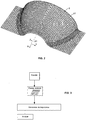
- the figure 2 illustrates a draping surface 9, this draping surface is a double curvature surface, and is defined by a mesh 91 finite elements.
- the figure 3 illustrates a vector field is obtained from a conventional rosette, such as a Cartesian rosette, comprising a reference mark defined by three orthogonal vectors X, Y, Z and a Cartesian transfer method.
- a conventional rosette such as a Cartesian rosette
- the vector X of the so-called global rosette is aligned with the main axis A 1 or axis of revolution of the layup surface.
- the vector field is obtained by Cartesian transfer of the vector X of the global rosette on each mesh 92 of the mesh, the transfer Cartesian vector X on the mesh consisting of a normal projection of the vector X on the plane of the mesh concerned, the projected vector of the so-called projected rosette constituting the vector vector 11 of the mesh.
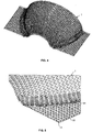
- the Figures 4 and 5 illustrate the resulting vector field 1.
- Fiber trajectories 81 for a 0 ° fold orientation can then be generated from this vector field 1, as illustrated in FIG. Figure 6A .
- Each trajectory is generated by defining the direction of the trajectory at different points of analysis, also called propagation points, the direction at a propagation point is that of the vector director of the mesh to which said propagation point belongs.
- a radius of curvature analysis can then be performed on these trajectories thus obtained.
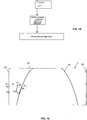
- the Figure 6B illustrates the minimum radius of curvature of each trajectory.
- This radius of curvature analysis shows large radii of curvature, incompatible for example with the placement of wicks of a quarter of an inch in width, for which a minimum radius of curvature of about 2 meters is conventionally recommended.
- radius of curvature and / or angular deflection can be performed directly from the vector field, without generating trajectories, this analysis can for example be visualized on the vector field by giving the vectors different colors depending on the values of the vector. radius of curvature or angular deflection.
- Fiber trajectories for other fold orientations may be generated from the same vector field 1, performing a corresponding rotation of the director vectors.
- the Figure 7A illustrates fiber trajectories for a 90 ° fold orientation, obtained by rotating the vectors of the vector field 1 by 90 °.
- Figure 7B illustrates the minimum radius of curvature of each trajectory.
- the figure 8 illustrates a obtained from a grid of constraints, in order to take into account design and / or manufacturing constraints in the definition of the trajectories, and thus to obtain trajectories with acceptable radii of curvature.
- a mesh 21 is defined from these geometrical constraints, each mesh of the mesh being formed of at least four nodes, then a constraint vector T is assigned to each node N of said mesh to form the grid of constraints 2.
- the direction vector of each mesh of the mesh is defined as follows.
- the normalized weights w 1 , w 2 , w 3 , w 4 are calculated at the projected point P ' 1 of the four nodes N 1 , N 2 , N 3 , N 4 which are associated with said projected point, namely the four nodes that define the mesh at which said projected point belongs.
- These normalized weights also called centroidal coordinates of the projected point, are calculated according to a method known per se, as a function of the distance between said projected point and said nodes.
- the vector vector of the mesh is then obtained by a transfer by normal projection of this vector D 1 to the central point P 1 of the mesh.
- the Figures 11 and 12 illustrate the resulting vector field 101, in which a director vector 111 is associated with each mesh.
- the Figures 13A and 13B respectively illustrate the trajectories 181 for a 0 ° fold, obtained from this vector field, and the results of the corresponding radius of curvature analysis.
- the Figures 14A and 14B respectively illustrate the trajectories 182 for a 90 ° fold, obtained from this vector field, after a 90 ° rotation of the director vectors, and the results of the corresponding radius of curvature analysis.
- Comparisons of Figures 6B and 7B with respectively the Figures 13B and 14B show that the trajectories obtained with the constraint grid have greater minimum radii of curvature than trajectories resulting from a Cartesian rosette.
- the figure 15 illustrates a vector field obtained from constraint curves.
- the geometric constraints represented in the form of the constraint grid 2 in the previous embodiment are here represented in the form of stress curves.
- the direction vector of each mesh of the mesh is defined as follows.
- the vector D 2 of the mesh corresponds to the director vector D 2 thus obtained.
- the vector field obtained from these stress curves 3 is similar to that obtained previously by means of the constraint grid.
- the figure 17 illustrates a vector field obtained from stress curves that are defined from an angular deflection grid.
- each cell is defined by four nodes N ', and assigning each node of the grid a maximum angular deflection value.
- An example of deviation values assigned to the different nodes is given to the figure 18 .
- Stress curves are generated on the draping surface by defining for each stress curve propagation directions at different points of analysis also called propagation points.
- the propagation direction at a propagation point P 3 is defined as follows.
- a reference direction is defined at said propagation point P 3 , this reference direction T R being in this embodiment a direction obtained by a Cartesian rosette, by normal projection transfer of the vector X of the overall rosette on the plane of the mesh of the draping surface to which said propagation point P 3 belongs.
- a normal projection of said point P 3 is carried out on the angular deflection grid, the projected point P ' 3 belonging for example to the mesh of the grid defined by the four nodes N' 1 , N ' 2 , N' 3 , N ' 4 .
- the standardized weights w 7 , w 8 , w 9 , w 10 are calculated at the projected point P ' 3 of the four nodes.
- These normalized weights, also called centroidal coordinates of the projected point are calculated according to a method known per se, as a function of the distance between said projected point and said nodes.
- An area of tolerance is then determined around the reference direction T R by defining limit directions L 1 and L 2 at an angle of + ⁇ and - ⁇ around the reference direction.
- a geodesic direction G corresponding to the direction of propagation at said propagation point P 3 of a geodesic curve is also determined.
- the reference direction is then reoriented within the limits of the allowed angular deflection value. If the geodesic direction G is included in the tolerance sector, then the direction of propagation at the point of propagation is defined as the geodesic direction. If the geodesic direction is not included in the tolerance sector, then the propagation direction at the propagation point is defined as the boundary direction L 1 or L 2 closest to the geodesic direction.
- the figure 20 illustrates an example of stress curves, designated under the general reference 303, obtained for 90 ° bends, from a Cartesian rosette and the angular deflection grid, with the angular deflection values indicated on the drawing. figure 18 .
- the obtaining of a vector field is carried out according to the method described above with the stress curves 3 of the figure 16 .
- the vector vector of each mesh of the mesh is defined in the following way. With reference to the figure 21 a normal projection of the central point P 4 of the mesh is made on the two nearest stress curves 331, 332. The two vectors T 11 , T 12 tangent to the curves are then defined at said projected points P ' 4 , P " 4.
- the standardized weights W 11 , W 12 are calculated at the central point P' of the two projected points, these normalized weights being function of the distances between the central point and the projected points
- the vector of the mesh corresponds to said vector D 3 , preferably after a 90 ° rotation of said vector D 3 to have a vector field concerning default 0 ° folds.
- the vector field 301 obtained from these stress curves is illustrated in FIG. figure 22 , the vector field comprising a director vector 311 associated with each mesh.
- the results of the analysis of radius of curvature of fiber trajectories, obtained from this vector field, or corresponding to the stress curves 303 of the figure 20 are illustrated in the figure 23 . These results show a significant increase in the minimum curvature radius of trajectories compared with the trajectories presented in Figure 7B and obtained simply by means of a Cartesian rosette.
- a vector field can also be obtained from a constraint vector grid and an angular deflection grid.
- the definition of the reference direction T R is carried out, not from the Cartesian rosette, but from the constraint vector grid, by normal projection of the point P 3 on the grid of constraints and definition of a vector D 1 according to the weighting method explained above with reference to the figure 10 .
- the reference direction T R of the mesh is then obtained by a transfer by normal projection of this vector D 1 to the point P 3 .
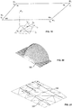
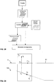
- the figure 24 illustrates an embodiment of the invention in which the vector field is obtained by using a transfer surface for the transfer of a Cartesian rosette.
- This type of vector field is suitable for defining trajectories on a non-continuous lay-up surface, such as the layup surface 109 illustrated in FIG. figure 26A .
- This draping surface is of generally frustoconical shape and comprises a central recess 194, forming ramps 195.
- a so-called continuous transfer surface is defined which corresponds to a simplified surface of the drape surface.
- the transfer surface corresponds to the drape surface without its central recess.
- This transfer surface is defined by a so-called transfer mesh.
- FIGS 26A and 26B illustrate trajectories 481 of 90 ° folds, obtained with such a vector field, after 90 ° rotation of the director vectors.
- Figure 31 illustrates the trajectories 581 obtained with a vector field defined from a rosette transfer directly to the drape surface, without use of the transfer surface.
- the trajectories are generated directly, without using a vector field.
- the vector field is obtained from a constraint vector grid and a transfer surface.
- the definition of the reference direction T ' R is carried out, not from the Cartesian rosette, but from the constraint vector grid, by normal projection of the point P' 5 on the grid of constraints and definition of a vector D 1 according to the weighting method explained above with reference to the figure 10 .
- the reference vector T ' R of the mesh is then obtained by a transfer by normal projection of this vector D 1 to the point P' 5 .
- the direction of propagation at point P 6 is then obtained as described above with reference to the figure 19 , using the maximum angular deflection value obtained from the angular deflection grid.
- the vector field is obtained from a constraint vector grid, an angular deflection grid and a transfer surface.
- the definition of the reference direction T " R is carried out, not from the Cartesian rosette, but from the constraint vector grid, by normal projection of the point P ' 6 on the constraint grid and definition of a vector D 1 according to the weighting method explained above with reference to the figure 10 .
- the reference vector T "R of the mesh is then obtained by a transfer by normal projection of this vector D 1 to the point P ' 6 .
- the vector field is obtained from a finite element mesh FEM, including direction data associated with each mesh, such as a FEM mesh from a design software, for example the software marketed under the trade name NASTRAN, with at least one angle associated with each mesh, and a rosette associated with said mesh.
- FEM mesh can be used directly at the input of the method according to the invention, or preferably be transformed in the form of a vector grid or stress curves.
- a vector field obtained according to the invention can be reintroduced at the input of the method according to the invention to obtain a new vector field.
- the vector vectors of the vector fields are all defined for an orientation at 0 °.
- a 90 ° rotation of the directional vectors is carried out to generate 90 ° trajectories.
- a rotation of plus or minus 45 ° of the direction vectors is performed to generate the trajectories at + 45 ° or -45 °.
Landscapes
- Engineering & Computer Science (AREA)
- Chemical & Material Sciences (AREA)
- Composite Materials (AREA)
- Mechanical Engineering (AREA)
- Human Computer Interaction (AREA)
- Manufacturing & Machinery (AREA)
- Physics & Mathematics (AREA)
- General Physics & Mathematics (AREA)
- Automation & Control Theory (AREA)
- Complex Calculations (AREA)
- Moulding By Coating Moulds (AREA)
Claims (2)
- Verfahren zum Definieren von Faserbahnen auf einer Drapierfläche zur Herstellung von mindestens einer Schicht mit einer gegebenen theoretischen Ausrichtung, dadurch gekennzeichnet, dass es Folgendes umfasst:- die Definition einer Vernetzung von fertigen Elementen der Drapierfläche,- wobei die Definition einer Vernetzung zur Übertragung einer kontinuierlichen Übertragungsfläche einer vereinfachten Oberfläche der Drapierfläche entspricht,wobei die Richtung einer Faser an einem Analysepunkt einer Masche der Drapierfläche erhalten wird durch- die Definition eines projizierten Punkts (P'5, P'6) durch normale Projektion eines Analysepunkts (P5, P6) der Masche auf die Übertragungsvernetzung (51),- die Definition einer Referenzrichtung (T'R, T"R) an dem projizierten Punkt (P'5), ausgehend von Richtungsdaten, die einem Übertragungsverfahren zugeordnet sind,- die Definition der Normalen (U1, U2) zur Übertragungsmasche,- die Definition einer Schnittebene (A2, A4), wobei die Schnittebene durch den projizierten Punkt (P'5, P'6), die Referenzrichtung (T'R, T"R) und die Normale (U1, U2) definiert ist,- die Definition der Schnittlinie (D4, D5) der Schnittebene (A2, A4) mit der Ebene (A3, A5) der Masche, wobei die Richtung der Faser am Analysepunkt ausgehend von der Richtung dieser Schnittlinie erhalten wird.
- Verfahren zur Herstellung von Teilen aus Verbundmaterial durch eine Maschine zum automatischen Drapieren von Fasern, dadurch gekennzeichnet, dass die Faserbahnen für die Drapierung von Schichten durch die Maschine zum Drapieren durch das Verfahren nach Anspruch 1 definiert sind.
Applications Claiming Priority (2)
| Application Number | Priority Date | Filing Date | Title |
|---|---|---|---|
| FR1301172A FR3006080B1 (fr) | 2013-05-22 | 2013-05-22 | Procede de definition de trajectoires de fibre a partir d'une surface de transfert |
| PCT/FR2014/000108 WO2014188084A1 (fr) | 2013-05-22 | 2014-05-20 | Procede de definition de trajectoires de fibre a partir d'une surface de transfert |
Publications (2)
| Publication Number | Publication Date |
|---|---|
| EP3000002A1 EP3000002A1 (de) | 2016-03-30 |
| EP3000002B1 true EP3000002B1 (de) | 2017-04-05 |
Family
ID=48979819
Family Applications (1)
| Application Number | Title | Priority Date | Filing Date |
|---|---|---|---|
| EP14729942.4A Active EP3000002B1 (de) | 2013-05-22 | 2014-05-20 | Verfahren zum definieren von faserpfaden aus einer transferoberfläche |
Country Status (4)
| Country | Link |
|---|---|
| US (1) | US9481135B2 (de) |
| EP (1) | EP3000002B1 (de) |
| FR (1) | FR3006080B1 (de) |
| WO (1) | WO2014188084A1 (de) |
Families Citing this family (7)
| Publication number | Priority date | Publication date | Assignee | Title |
|---|---|---|---|---|
| FR3006079B1 (fr) | 2013-05-22 | 2015-05-15 | Coriolis Software | Procede de definition de trajectoires de fibre a partir de courbes ou grille de contrainte |
| FR3006078B1 (fr) * | 2013-05-22 | 2016-06-03 | Coriolis Software | Procede de definition de trajectoires de fibre a partir d'un champ vectoriel |
| US9545759B2 (en) * | 2015-01-30 | 2017-01-17 | CGTech | Automated fiber placement with course trajectory compensation |
| US12240178B1 (en) | 2020-06-18 | 2025-03-04 | The Boeing Company | Layup strategy analysis |
| US11436390B2 (en) * | 2020-06-18 | 2022-09-06 | The Boeing Company | Fiber path planning to reduce in-plane curvature |
| CN114004126B (zh) * | 2021-11-05 | 2023-06-09 | 上海索辰信息科技股份有限公司 | 一种复合材料铺层的网格密度优化仿真分析方法 |
| CN116186962B (zh) * | 2022-09-07 | 2026-03-24 | 中国飞机强度研究所 | 一种复合材料层合板各层铺放带曲线铺放轨迹确定方法 |
Family Cites Families (5)
| Publication number | Priority date | Publication date | Assignee | Title |
|---|---|---|---|---|
| US4696707A (en) * | 1987-08-18 | 1987-09-29 | The Ingersoll Milling Machine Company | Composite tape placement apparatus with natural path generation means |
| JPH0725145B2 (ja) * | 1988-05-24 | 1995-03-22 | 新日本工機株式会社 | テープの自動貼付装置におけるテープの進行方向制御方法 |
| US8709576B2 (en) * | 2008-11-21 | 2014-04-29 | Airbus Operations (Sas) | Curved structural part made of composite material and a process for manufacturing such a part |
| FR3006079B1 (fr) * | 2013-05-22 | 2015-05-15 | Coriolis Software | Procede de definition de trajectoires de fibre a partir de courbes ou grille de contrainte |
| FR3006078B1 (fr) * | 2013-05-22 | 2016-06-03 | Coriolis Software | Procede de definition de trajectoires de fibre a partir d'un champ vectoriel |
-
2013
- 2013-05-22 FR FR1301172A patent/FR3006080B1/fr not_active Expired - Fee Related
-
2014
- 2014-05-20 EP EP14729942.4A patent/EP3000002B1/de active Active
- 2014-05-20 WO PCT/FR2014/000108 patent/WO2014188084A1/fr not_active Ceased
- 2014-05-20 US US14/893,310 patent/US9481135B2/en active Active
Non-Patent Citations (1)
| Title |
|---|
| None * |
Also Published As
| Publication number | Publication date |
|---|---|
| WO2014188084A1 (fr) | 2014-11-27 |
| FR3006080B1 (fr) | 2015-05-15 |
| US20160082672A1 (en) | 2016-03-24 |
| FR3006080A1 (fr) | 2014-11-28 |
| EP3000002A1 (de) | 2016-03-30 |
| US9481135B2 (en) | 2016-11-01 |
Similar Documents
| Publication | Publication Date | Title |
|---|---|---|
| EP3000003B1 (de) | Verfahren zum definieren von faserpfaden aus einem bedingungsgitter oder bedingungskurven | |
| EP3000001B1 (de) | Verfahren zum definieren von fasertrajektorien auf der basis eines vektorfeldes | |
| WO2014188084A1 (fr) | Procede de definition de trajectoires de fibre a partir d'une surface de transfert | |
| Barequet et al. | Filling gaps in the boundary of a polyhedron | |
| Campen et al. | Exact and robust (self‐) intersections for polygonal meshes | |
| EP3481613B1 (de) | Verfahren zur herstellung einer vorform für verbundwerkstoffe | |
| CA2648901A1 (fr) | Procede de choix d'un arrangement de secteurs pour un distributeur pour turbomachine | |
| EP1973435A1 (de) | Vorrichtung und verfahren für das bekleidungsdesign | |
| CN103838907A (zh) | 基于stl模型的曲面切割轨迹获得方法 | |
| Skraba et al. | 2D vector field simplification based on robustness | |
| US7720649B2 (en) | Reverse engineering method for disk and blade attachments | |
| EP4193334B1 (de) | Verfahren zur charakterisierung einer gewebten faserstruktur | |
| EP3274160B1 (de) | Verfahren zur herstellung einer kontrollklinge zur kalibrierung einer tomographischen inspektion und resultierende kontrollklinge | |
| CA2934052C (fr) | Aube pour roue a aubes de turbomachine et procede de modelisation de celle-ci | |
| US11436390B2 (en) | Fiber path planning to reduce in-plane curvature | |
| EP4076911A1 (de) | Verfahren zum herstellen eines aus einem verbundwerkstoff gefertigten gitters | |
| EP2359339A1 (de) | Computerunterstütztes entwurfsverfahren zum erzeugen einer oberfläche in einem komplexen system | |
| FR2952454A1 (fr) | Procede et outil de simulation du comportement aerodynamique d'un element aerodynamique d'un aeronef presentant un angle de fleche variable | |
| EP3434457B1 (de) | Verfahren zur herstellung eines teils durch automatisierte faserplatzierung | |
| Foteinos et al. | Fully generalized two-dimensional constrained Delaunay mesh refinement | |
| FR2797212A1 (fr) | Procede de fabrication d'un objet en materiau composite renforce par des fibres, tel qu'une portion d'une pale de rotor pour un aeronef, et objet obtenu par ce procede | |
| Halbritter | Leveraging Automated Fiber Placement Computer Aided Process Planning Framework for Defect Validation and Dynamic Layup Strategies | |
| CA2933628C (fr) | Aube, roue a aubes et turbomachine; procede de fabrication de l'aube | |
| WO2014154981A1 (fr) | Procede de conception d'une preforme commune pour la realisation de preformes d'aubes directrices de sortie de turbomachine en materiau composite a profils geometriques differents. | |
| EP4323179A1 (de) | Gekrümmte versteifung für eine turbinentriebwerksgondel und verfahren zur herstellung solch einer versteifung |
Legal Events
| Date | Code | Title | Description |
|---|---|---|---|
| PUAI | Public reference made under article 153(3) epc to a published international application that has entered the european phase |
Free format text: ORIGINAL CODE: 0009012 |
|
| 17P | Request for examination filed |
Effective date: 20151222 |
|
| AK | Designated contracting states |
Kind code of ref document: A1 Designated state(s): AL AT BE BG CH CY CZ DE DK EE ES FI FR GB GR HR HU IE IS IT LI LT LU LV MC MK MT NL NO PL PT RO RS SE SI SK SM TR |
|
| AX | Request for extension of the european patent |
Extension state: BA ME |
|
| DAX | Request for extension of the european patent (deleted) | ||
| GRAP | Despatch of communication of intention to grant a patent |
Free format text: ORIGINAL CODE: EPIDOSNIGR1 |
|
| INTG | Intention to grant announced |
Effective date: 20161212 |
|
| GRAS | Grant fee paid |
Free format text: ORIGINAL CODE: EPIDOSNIGR3 |
|
| GRAA | (expected) grant |
Free format text: ORIGINAL CODE: 0009210 |
|
| AK | Designated contracting states |
Kind code of ref document: B1 Designated state(s): AL AT BE BG CH CY CZ DE DK EE ES FI FR GB GR HR HU IE IS IT LI LT LU LV MC MK MT NL NO PL PT RO RS SE SI SK SM TR |
|
| REG | Reference to a national code |
Ref country code: GB Ref legal event code: FG4D Free format text: NOT ENGLISH |
|
| REG | Reference to a national code |
Ref country code: CH Ref legal event code: EP |
|
| REG | Reference to a national code |
Ref country code: AT Ref legal event code: REF Ref document number: 882367 Country of ref document: AT Kind code of ref document: T Effective date: 20170415 |
|
| REG | Reference to a national code |
Ref country code: FR Ref legal event code: PLFP Year of fee payment: 4 |
|
| REG | Reference to a national code |
Ref country code: IE Ref legal event code: FG4D Free format text: LANGUAGE OF EP DOCUMENT: FRENCH |
|
| REG | Reference to a national code |
Ref country code: DE Ref legal event code: R096 Ref document number: 602014008363 Country of ref document: DE |
|
| REG | Reference to a national code |
Ref country code: NL Ref legal event code: MP Effective date: 20170405 |
|
| REG | Reference to a national code |
Ref country code: LT Ref legal event code: MG4D |
|
| REG | Reference to a national code |
Ref country code: AT Ref legal event code: MK05 Ref document number: 882367 Country of ref document: AT Kind code of ref document: T Effective date: 20170405 |
|
| PG25 | Lapsed in a contracting state [announced via postgrant information from national office to epo] |
Ref country code: NL Free format text: LAPSE BECAUSE OF FAILURE TO SUBMIT A TRANSLATION OF THE DESCRIPTION OR TO PAY THE FEE WITHIN THE PRESCRIBED TIME-LIMIT Effective date: 20170405 |
|
| PG25 | Lapsed in a contracting state [announced via postgrant information from national office to epo] |
Ref country code: GR Free format text: LAPSE BECAUSE OF FAILURE TO SUBMIT A TRANSLATION OF THE DESCRIPTION OR TO PAY THE FEE WITHIN THE PRESCRIBED TIME-LIMIT Effective date: 20170706 Ref country code: FI Free format text: LAPSE BECAUSE OF FAILURE TO SUBMIT A TRANSLATION OF THE DESCRIPTION OR TO PAY THE FEE WITHIN THE PRESCRIBED TIME-LIMIT Effective date: 20170405 Ref country code: NO Free format text: LAPSE BECAUSE OF FAILURE TO SUBMIT A TRANSLATION OF THE DESCRIPTION OR TO PAY THE FEE WITHIN THE PRESCRIBED TIME-LIMIT Effective date: 20170705 Ref country code: ES Free format text: LAPSE BECAUSE OF FAILURE TO SUBMIT A TRANSLATION OF THE DESCRIPTION OR TO PAY THE FEE WITHIN THE PRESCRIBED TIME-LIMIT Effective date: 20170405 Ref country code: LT Free format text: LAPSE BECAUSE OF FAILURE TO SUBMIT A TRANSLATION OF THE DESCRIPTION OR TO PAY THE FEE WITHIN THE PRESCRIBED TIME-LIMIT Effective date: 20170405 Ref country code: HR Free format text: LAPSE BECAUSE OF FAILURE TO SUBMIT A TRANSLATION OF THE DESCRIPTION OR TO PAY THE FEE WITHIN THE PRESCRIBED TIME-LIMIT Effective date: 20170405 Ref country code: AT Free format text: LAPSE BECAUSE OF FAILURE TO SUBMIT A TRANSLATION OF THE DESCRIPTION OR TO PAY THE FEE WITHIN THE PRESCRIBED TIME-LIMIT Effective date: 20170405 |
|
| PG25 | Lapsed in a contracting state [announced via postgrant information from national office to epo] |
Ref country code: PL Free format text: LAPSE BECAUSE OF FAILURE TO SUBMIT A TRANSLATION OF THE DESCRIPTION OR TO PAY THE FEE WITHIN THE PRESCRIBED TIME-LIMIT Effective date: 20170405 Ref country code: IS Free format text: LAPSE BECAUSE OF FAILURE TO SUBMIT A TRANSLATION OF THE DESCRIPTION OR TO PAY THE FEE WITHIN THE PRESCRIBED TIME-LIMIT Effective date: 20170805 Ref country code: RS Free format text: LAPSE BECAUSE OF FAILURE TO SUBMIT A TRANSLATION OF THE DESCRIPTION OR TO PAY THE FEE WITHIN THE PRESCRIBED TIME-LIMIT Effective date: 20170405 Ref country code: BG Free format text: LAPSE BECAUSE OF FAILURE TO SUBMIT A TRANSLATION OF THE DESCRIPTION OR TO PAY THE FEE WITHIN THE PRESCRIBED TIME-LIMIT Effective date: 20170705 Ref country code: LV Free format text: LAPSE BECAUSE OF FAILURE TO SUBMIT A TRANSLATION OF THE DESCRIPTION OR TO PAY THE FEE WITHIN THE PRESCRIBED TIME-LIMIT Effective date: 20170405 Ref country code: SE Free format text: LAPSE BECAUSE OF FAILURE TO SUBMIT A TRANSLATION OF THE DESCRIPTION OR TO PAY THE FEE WITHIN THE PRESCRIBED TIME-LIMIT Effective date: 20170405 |
|
| REG | Reference to a national code |
Ref country code: CH Ref legal event code: PL |
|
| REG | Reference to a national code |
Ref country code: DE Ref legal event code: R097 Ref document number: 602014008363 Country of ref document: DE |
|
| PG25 | Lapsed in a contracting state [announced via postgrant information from national office to epo] |
Ref country code: CZ Free format text: LAPSE BECAUSE OF FAILURE TO SUBMIT A TRANSLATION OF THE DESCRIPTION OR TO PAY THE FEE WITHIN THE PRESCRIBED TIME-LIMIT Effective date: 20170405 Ref country code: DK Free format text: LAPSE BECAUSE OF FAILURE TO SUBMIT A TRANSLATION OF THE DESCRIPTION OR TO PAY THE FEE WITHIN THE PRESCRIBED TIME-LIMIT Effective date: 20170405 Ref country code: RO Free format text: LAPSE BECAUSE OF FAILURE TO SUBMIT A TRANSLATION OF THE DESCRIPTION OR TO PAY THE FEE WITHIN THE PRESCRIBED TIME-LIMIT Effective date: 20170405 Ref country code: MC Free format text: LAPSE BECAUSE OF FAILURE TO SUBMIT A TRANSLATION OF THE DESCRIPTION OR TO PAY THE FEE WITHIN THE PRESCRIBED TIME-LIMIT Effective date: 20170405 Ref country code: EE Free format text: LAPSE BECAUSE OF FAILURE TO SUBMIT A TRANSLATION OF THE DESCRIPTION OR TO PAY THE FEE WITHIN THE PRESCRIBED TIME-LIMIT Effective date: 20170405 Ref country code: SK Free format text: LAPSE BECAUSE OF FAILURE TO SUBMIT A TRANSLATION OF THE DESCRIPTION OR TO PAY THE FEE WITHIN THE PRESCRIBED TIME-LIMIT Effective date: 20170405 |
|
| PLBE | No opposition filed within time limit |
Free format text: ORIGINAL CODE: 0009261 |
|
| STAA | Information on the status of an ep patent application or granted ep patent |
Free format text: STATUS: NO OPPOSITION FILED WITHIN TIME LIMIT |
|
| REG | Reference to a national code |
Ref country code: IE Ref legal event code: MM4A |
|
| PG25 | Lapsed in a contracting state [announced via postgrant information from national office to epo] |
Ref country code: CH Free format text: LAPSE BECAUSE OF NON-PAYMENT OF DUE FEES Effective date: 20170531 Ref country code: IT Free format text: LAPSE BECAUSE OF FAILURE TO SUBMIT A TRANSLATION OF THE DESCRIPTION OR TO PAY THE FEE WITHIN THE PRESCRIBED TIME-LIMIT Effective date: 20170405 Ref country code: SM Free format text: LAPSE BECAUSE OF FAILURE TO SUBMIT A TRANSLATION OF THE DESCRIPTION OR TO PAY THE FEE WITHIN THE PRESCRIBED TIME-LIMIT Effective date: 20170405 Ref country code: LI Free format text: LAPSE BECAUSE OF NON-PAYMENT OF DUE FEES Effective date: 20170531 |
|
| 26N | No opposition filed |
Effective date: 20180108 |
|
| PG25 | Lapsed in a contracting state [announced via postgrant information from national office to epo] |
Ref country code: LU Free format text: LAPSE BECAUSE OF NON-PAYMENT OF DUE FEES Effective date: 20170520 |
|
| REG | Reference to a national code |
Ref country code: FR Ref legal event code: PLFP Year of fee payment: 5 |
|
| REG | Reference to a national code |
Ref country code: BE Ref legal event code: MM Effective date: 20170531 |
|
| PG25 | Lapsed in a contracting state [announced via postgrant information from national office to epo] |
Ref country code: IE Free format text: LAPSE BECAUSE OF NON-PAYMENT OF DUE FEES Effective date: 20170520 |
|
| PG25 | Lapsed in a contracting state [announced via postgrant information from national office to epo] |
Ref country code: SI Free format text: LAPSE BECAUSE OF FAILURE TO SUBMIT A TRANSLATION OF THE DESCRIPTION OR TO PAY THE FEE WITHIN THE PRESCRIBED TIME-LIMIT Effective date: 20170405 |
|
| PG25 | Lapsed in a contracting state [announced via postgrant information from national office to epo] |
Ref country code: BE Free format text: LAPSE BECAUSE OF NON-PAYMENT OF DUE FEES Effective date: 20170531 |
|
| REG | Reference to a national code |
Ref country code: DE Ref legal event code: R081 Ref document number: 602014008363 Country of ref document: DE Owner name: CORIOLIS COMPOSITES TECHNOLOGIES SAS, FR Free format text: FORMER OWNER: CORIOLIS SOFTWARE, QUEVEN, FR |
|
| PG25 | Lapsed in a contracting state [announced via postgrant information from national office to epo] |
Ref country code: MT Free format text: LAPSE BECAUSE OF FAILURE TO SUBMIT A TRANSLATION OF THE DESCRIPTION OR TO PAY THE FEE WITHIN THE PRESCRIBED TIME-LIMIT Effective date: 20170405 |
|
| REG | Reference to a national code |
Ref country code: GB Ref legal event code: 732E Free format text: REGISTERED BETWEEN 20190131 AND 20190206 |
|
| PG25 | Lapsed in a contracting state [announced via postgrant information from national office to epo] |
Ref country code: HU Free format text: LAPSE BECAUSE OF FAILURE TO SUBMIT A TRANSLATION OF THE DESCRIPTION OR TO PAY THE FEE WITHIN THE PRESCRIBED TIME-LIMIT; INVALID AB INITIO Effective date: 20140520 |
|
| PG25 | Lapsed in a contracting state [announced via postgrant information from national office to epo] |
Ref country code: CY Free format text: LAPSE BECAUSE OF FAILURE TO SUBMIT A TRANSLATION OF THE DESCRIPTION OR TO PAY THE FEE WITHIN THE PRESCRIBED TIME-LIMIT Effective date: 20170405 |
|
| PG25 | Lapsed in a contracting state [announced via postgrant information from national office to epo] |
Ref country code: MK Free format text: LAPSE BECAUSE OF FAILURE TO SUBMIT A TRANSLATION OF THE DESCRIPTION OR TO PAY THE FEE WITHIN THE PRESCRIBED TIME-LIMIT Effective date: 20170405 |
|
| PG25 | Lapsed in a contracting state [announced via postgrant information from national office to epo] |
Ref country code: TR Free format text: LAPSE BECAUSE OF FAILURE TO SUBMIT A TRANSLATION OF THE DESCRIPTION OR TO PAY THE FEE WITHIN THE PRESCRIBED TIME-LIMIT Effective date: 20170405 |
|
| PG25 | Lapsed in a contracting state [announced via postgrant information from national office to epo] |
Ref country code: PT Free format text: LAPSE BECAUSE OF FAILURE TO SUBMIT A TRANSLATION OF THE DESCRIPTION OR TO PAY THE FEE WITHIN THE PRESCRIBED TIME-LIMIT Effective date: 20170405 |
|
| PG25 | Lapsed in a contracting state [announced via postgrant information from national office to epo] |
Ref country code: AL Free format text: LAPSE BECAUSE OF FAILURE TO SUBMIT A TRANSLATION OF THE DESCRIPTION OR TO PAY THE FEE WITHIN THE PRESCRIBED TIME-LIMIT Effective date: 20170405 |
|
| PGFP | Annual fee paid to national office [announced via postgrant information from national office to epo] |
Ref country code: GB Payment date: 20220426 Year of fee payment: 9 Ref country code: DE Payment date: 20220420 Year of fee payment: 9 |
|
| REG | Reference to a national code |
Ref country code: DE Ref legal event code: R119 Ref document number: 602014008363 Country of ref document: DE |
|
| GBPC | Gb: european patent ceased through non-payment of renewal fee |
Effective date: 20230520 |
|
| PG25 | Lapsed in a contracting state [announced via postgrant information from national office to epo] |
Ref country code: DE Free format text: LAPSE BECAUSE OF NON-PAYMENT OF DUE FEES Effective date: 20231201 Ref country code: GB Free format text: LAPSE BECAUSE OF NON-PAYMENT OF DUE FEES Effective date: 20230520 |
|
| PGFP | Annual fee paid to national office [announced via postgrant information from national office to epo] |
Ref country code: FR Payment date: 20250423 Year of fee payment: 12 |