EP2999947B1 - Ultraschall-durchflussmessgerät mit zwei ultraschallwandler-montageanordnungen - Google Patents
Ultraschall-durchflussmessgerät mit zwei ultraschallwandler-montageanordnungen Download PDFInfo
- Publication number
- EP2999947B1 EP2999947B1 EP14720947.2A EP14720947A EP2999947B1 EP 2999947 B1 EP2999947 B1 EP 2999947B1 EP 14720947 A EP14720947 A EP 14720947A EP 2999947 B1 EP2999947 B1 EP 2999947B1
- Authority
- EP
- European Patent Office
- Prior art keywords
- ultrasonic
- clamping surface
- rolling elements
- bearing
- ultrasonic transducer
- Prior art date
- Legal status (The legal status is an assumption and is not a legal conclusion. Google has not performed a legal analysis and makes no representation as to the accuracy of the status listed.)
- Active
Links
Images



Classifications
-
- G—PHYSICS
- G10—MUSICAL INSTRUMENTS; ACOUSTICS
- G10K—SOUND-PRODUCING DEVICES; METHODS OR DEVICES FOR PROTECTING AGAINST, OR FOR DAMPING, NOISE OR OTHER ACOUSTIC WAVES IN GENERAL; ACOUSTICS NOT OTHERWISE PROVIDED FOR
- G10K11/00—Methods or devices for transmitting, conducting or directing sound in general; Methods or devices for protecting against, or for damping, noise or other acoustic waves in general
- G10K11/004—Mounting transducers, e.g. provided with mechanical moving or orienting device
-
- G—PHYSICS
- G01—MEASURING; TESTING
- G01F—MEASURING VOLUME, VOLUME FLOW, MASS FLOW OR LIQUID LEVEL; METERING BY VOLUME
- G01F1/00—Measuring the volume flow or mass flow of fluid or fluent solid material wherein the fluid passes through a meter in a continuous flow
- G01F1/66—Measuring the volume flow or mass flow of fluid or fluent solid material wherein the fluid passes through a meter in a continuous flow by measuring frequency, phase shift or propagation time of electromagnetic or other waves, e.g. using ultrasonic flowmeters
- G01F1/662—Constructional details
-
- G—PHYSICS
- G01—MEASURING; TESTING
- G01F—MEASURING VOLUME, VOLUME FLOW, MASS FLOW OR LIQUID LEVEL; METERING BY VOLUME
- G01F15/00—Details of, or accessories for, apparatus of groups G01F1/00 - G01F13/00 insofar as such details or appliances are not adapted to particular types of such apparatus
- G01F15/18—Supports or connecting means for meters
-
- G—PHYSICS
- G01—MEASURING; TESTING
- G01N—INVESTIGATING OR ANALYSING MATERIALS BY DETERMINING THEIR CHEMICAL OR PHYSICAL PROPERTIES
- G01N29/00—Investigating or analysing materials by the use of ultrasonic, sonic or infrasonic waves; Visualisation of the interior of objects by transmitting ultrasonic or sonic waves through the object
- G01N29/22—Details, e.g. general constructional or apparatus details
- G01N29/222—Constructional or flow details for analysing fluids
-
- G—PHYSICS
- G01—MEASURING; TESTING
- G01N—INVESTIGATING OR ANALYSING MATERIALS BY DETERMINING THEIR CHEMICAL OR PHYSICAL PROPERTIES
- G01N29/00—Investigating or analysing materials by the use of ultrasonic, sonic or infrasonic waves; Visualisation of the interior of objects by transmitting ultrasonic or sonic waves through the object
- G01N29/22—Details, e.g. general constructional or apparatus details
- G01N29/223—Supports, positioning or alignment in fixed situation
Definitions
- the invention relates to an ultrasonic flowmeter with two ultrasonic transducer mounting arrangements according to the preamble of claim 1.
- Ultrasonic flowmeters are widely used in process and automation technology. They allow in a simple way to determine the volume flow and / or mass flow in a pipeline.
- the known ultrasonic flowmeters often work according to the transit time difference principle.
- the transit time difference principle the different transit times of ultrasonic waves, in particular ultrasonic pulses, so-called bursts, are evaluated relative to the flow direction of the liquid.
- ultrasonic pulses are sent at a certain angle to the pipe axis both with and against the flow.
- the runtime difference can be used to determine the flow velocity and, with a known diameter of the pipe section, the volume flow rate.
- the ultrasonic waves are generated or received with the help of so-called ultrasonic transducers.
- ultrasonic transducers are firmly mounted in the pipe wall of the respective pipe section.
- Clamp-on ultrasonic flow measurement systems are also available. In these systems, the ultrasonic transducers are pressed from outside the measuring tube to the tube wall.
- a big advantage of clamp-on ultrasonic flow measuring systems is that they can not touch the measuring medium and can be mounted on an already existing pipeline.
- the ultrasonic transducers normally consist of an electromechanical transducer element, eg a piezoelectric element, and a coupling layer. In clamp-on systems, the ultrasonic waves are generated as acoustic signals in the electromechanical transducer element and passed over the coupling layer to the pipe wall and passed from there into the liquid.
- the acoustic signals are coupled into the measuring medium via the coupling layer.
- the ultrasonic transducers are usually located in a common plane on the measuring tube, either on opposite sides of the measuring tube, then the acoustic signal, projected on a tube cross-section, passes once along a secant through the Measuring tube, or on the same side of the measuring tube, then the acoustic signal is reflected on the opposite side of the measuring tube, whereby the acoustic signal passes twice through the measuring tube along the projected on the cross section through the measuring tube secant.
- a first ultrasonic transducer sends acoustic signals into the measuring tube which propagate through the medium.
- the acoustic signals are received by a second ultrasonic transducer.
- the second ultrasonic transducer emits acoustic signals received from the second ultrasonic transducer. If a medium flows through the measuring tube, different transit times result for the first and the second process. From these two transit times, the flow rate of the medium in the measuring tube is determined.
- the transmitting ultrasonic transducer generates in addition to the acoustic signal and an acoustic noise, which is transmitted from an ultrasonic transducer housing to the measuring tube and the measuring tube to the receiving ultrasonic transducer.
- the ultrasonic transducer housing is decoupled from the measuring tube with polymer or elastomeric dampers to minimize the transmission of acoustic noise.
- polymers or elastomers are of low strength and durability.
- the object is achieved by an ultrasonic flowmeter with two ultrasonic transducer mounting arrangements according to claim 1.
- the ultrasonic transducer mounting assembly according to the invention comprises an ultrasonic transducer element, a transducer housing in which the ultrasonic transducer element is arranged, and a receiving unit, wherein the transducer housing is clamped in the receiving unit in a clamping distance, wherein the clamping distance according to the invention at least one roller bearing with at least one rolling element, in particular at least a ball bearing with at least one ball, for acoustic decoupling of the converter housing from the receiving unit comprises.
- the clamping path is generally defined as an arrangement of bodies clamped against each other.
- rolling elements By using rolling elements, the contact area between the transducer housing and receiving unit is minimized, whereby the acoustic coupling of the converter housing and receiving unit is minimized.
- the rolling elements consist of balls
- the sound passes through a quasi point-like contact between the receiving unit and the ball in the ball and spreads in all directions.
- the sound waves that have entered the sphere are reflected in the sphere until the sound waves have subsided.
- the roller bearing can be designed to be movable or rigid due to the rolling elements.
- the converter housing has at least one first clamping surface and the receiving unit has at least one second clamping surface, wherein a rolling element bearing is formed from a clamping surface of the converter housing and a clamping surface of the receiving unit and rolling elements between the two clamping surfaces.
- the rolling elements of the rolling element bearing are formed barrel-shaped.
- the converter housing in the receiving unit in the clamping section by means of at least one spring, in particular by means of at least one plate spring and / or by means of at least one coil spring, biased.
- the rolling elements of the rolling element bearing comprise metal, ceramic, plastic, glass or a composite.
- the converter housing has a first and a second clamping surface and the receiving unit has a first and a second clamping surface, wherein a first roller bearing of rolling elements between the first clamping surface of the converter housing and the first clamping surface of the receiving unit is formed and a second roller bearing of rolling elements between the second clamping surface of the converter housing and the second clamping surface of the receiving unit is formed.
- the rolling bearing comprises a plurality of rolling elements, which are taken by a bearing ring or a particular cylindrical cover.
- Alternative lid forms e.g. oval lids are also possible.
- the bearing ring may be part of the rolling bearing.
- the cover is more likely to be assigned to the converter housing.
- the inner wall of the lid itself forms the version of the rolling elements. The Anorndung in the lid has the additional advantage of a material savings.
- the bearing ring or the cover has a central axis and that the rolling elements are taken in such a way that a radial movement of the rolling elements is blocked or limited relative to the central axis.
- the rolling elements can be used as a kind of rolling element package in the mounting arrangement.
- the blockade or the limitation can be done either by the interaction of the rolling elements themselves, which has a material savings result.
- the blockage or limitation may be through a center socket, preferably a ring. This is arranged inside the bearing ring.
- the rolling bearing may be formed as a commercially available ball bearing, which is available as a mass product of various sizes commercially and inexpensively.
- an O-ring can be used, which is disposed within the bearing ring of the lid, for example in an annular groove.
- the receiving unit projects at least partially into the measuring tube or into the container.
- the object of the invention is also achieved by an ultrasonic flowmeter with an ultrasonic measuring device according to the invention.
- the ultrasonic flowmeter according to the invention comprises at least one first and one second ultrasonic transducer mounting arrangement according to the invention, which are arranged on the measuring tube such that ultrasonic signals are transmitted through the volume of the measuring tube through which a medium flows from a first ultrasonic transducer of the first ultrasonic transducer mounting arrangement a second ultrasonic transducer of the second ultrasonic transducer mounting assembly and vice versa can run.
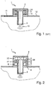
- Fig. 1 shows a longitudinal section through an ultrasonic transducer mounting assembly 1 according to the prior art.
- a hollow-cylindrical converter housing 3 has an ultrasonic transducer element 2 on an inner first end face.
- the ultrasonic transducer element 2 is formed of a piezoelectric material to emit acoustic signals 15 through the first end face of the transducer housing 3.
- the converter housing 3 has a flange 27.
- the converter housing 3 protrudes partially into a measuring tube 13, so that the ultrasonic transducer element 2 in the measuring tube 13 and the flange 27 are arranged outside the measuring tube 13.
- the protruding from the measuring tube 13 part of the transducer housing 3 is surrounded by a receiving unit 4, wherein the receiving unit 4 is cylindrical and is arranged on a first end face on the measuring tube 13.
- the flange 27 is held by means of a first and a second O-ring 11, 24, wherein the first O-ring 11 is disposed between an inner surface of the receiving unit 4 adjacent to the measuring tube 13 and the flange 27 and the second O-ring 24 is disposed between the flange 27 and an inner end surface of the receiving unit 4 opposite the measuring tube 13.
- the ultrasonic transducer 2 emits ultrasonic signals 15, which propagate in the medium of the measuring tube 13 and reach a second ultrasonic transducer of a second ultrasonic transducer mounting arrangement for transit time determination.
- the ultrasonic signals 15 also propagate through the transducer housing 3, the receiving unit 4 and the measuring tube 13 in the form of an acoustic noise 14. This noise 14 is suppressed according to the invention.
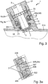
- Fig. 2 shows a longitudinal section through an ultrasonic transducer mounting assembly according to the invention.
- the rolling elements 7, the receiving unit 4 and the converter housing 3 are metallic, in particular made of steel.
- the inner end face of the receiving unit 4 resting against the measuring tube 13 defines a first clamping surface 9 of the receiving unit 4.
- the measuring tube 13 facing side of the flange 27 defines a first clamping surface 8 of the converter housing 3.
- the first clamping surface 8 of the transducer housing 3 and the first clamping surface 9 of the receiving unit 4 with the rolling elements 7 between them define a first roller bearing 6, the rolling elements between the flange 27th and the inner end face of the receiving unit 4 resting against the measuring tube 13 are rotatably mounted.
- rotatability does not matter in the context of the present invention.
- the measuring tube 13 facing away from the surface of the flange 27 defines a second clamping surface 28 of the converter housing third
- the measuring tube 13 facing the inner surface of the receiving unit 4 defines a second clamping surface of the receiving unit. 4
- the second clamping surface of the converter housing 3 and the second clamping surface of the receiving unit 4 with the rolling elements 7 therebetween define a second roller bearing 23.
- the rolling elements 7 of the first and second Wälz analyseslagers 6, 23 are mounted so that the converter housing 3 is rotatably supported about its longitudinal axis 5. Regardless of the first and the second roller bearing 6, 23, a third
- Rolling element bearing which is not shown here, be arranged radially on the flange 27.
- the storage of the converter housing 3 in the receiving unit 4 has a high strength and high resistance and at the same time have the quasi punctiform contacts between the rolling elements 7 and the receiving unit 4 and the flange 27 of the transducer housing 3, a constriction of the sound path, so that the noise 14 of the acoustic signal is largely suppressed.
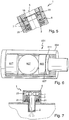
- Fig. 3 and Fig. 3a show a longitudinal section and an enlarged detail of a longitudinal section through an embodiment of the ultrasonic mounting assembly 1 according to the invention in accordance with the general structure in Fig. 2 , which is integrated in a measuring tube 313.
- a receiving unit 304 and the measuring tube 313 are integrally formed.
- a longitudinal axis 5 of the converter housing 3 is arranged obliquely to a longitudinal axis of the measuring tube 313.
- the receiving unit 304 has a longitudinal axis 5, which coincides with the longitudinal axis 5 of the converter housing 3.
- a ring-shaped first shoulder 21 is arranged matching a flange 327, which holds the flange 327.
- a plate spring 10 Between the flange 327 and the first shoulder 21, a plate spring 10, a shoulder ring 322 and rolling elements 7 are arranged.
- the flange 327 has, in the direction of the measuring tube 313, a second shoulder 325, which defines a first clamping surface 308 of the converter housing 3.
- the shoulder ring 322 has an annular relief defining a first clamping surface 309 of the receiving unit 304.
- the first clamping surface 308 of the converter housing 3 and the first clamping surface 309 of the receiving unit 304 together with the rolling elements 7 define therebetween the first roller bearing 6.
- an O-ring 11 is arranged so that a medium 18 from the measuring tube 313 can not get into the interior of the receiving unit 304.
- the O-ring 11 is in particular clamped between a jacket surface of the converter housing and an opposite wall of the receiving unit 304.
- a first thread 19 is arranged at a, opposite the measuring tube 313 second end portion of the receiving unit 304.
- a hold-down 17 having a second thread 20 mating with the first thread 19 closes the receiving unit 304 at the second end portion. Between the hold-down 17 and the flange 327 rolling elements 7 are arranged.
- a first annular groove 30 is arranged, which defines a second clamping surface 328 of the transducer housing 3.
- An end face of the hold-down 17 facing the measuring tube 313 defines a second clamping face 329 of the receiving unit 4.
- the second clamping face 328 of the transducer housing 3 and the second clamping face 329 of the receiving unit 4 with the rolling elements 7 therebetween define the second rolling-element bearing 23.
- the clamping surfaces 308, 309, 328, 329 have a greater radius of curvature than the rolling elements 7.
- Fig. 4 and Fig. 4a show a longitudinal section or an enlarged section of a longitudinal section through a further embodiment of an ultrasonic transducer mounting assembly 1 according to the invention Fig. 3 ,
- a first clamping surface 408 of a transducer housing 3, which faces a measuring tube 313, is planar.
- Rolling elements 7 of a first roller bearing 6 are clamped against the clamping surface 408.
- On one of the clamping surface 408 opposite side of the rolling elements 7 of the first rolling element bearing 6, a shoulder ring 422 is arranged.
- the shoulder ring 422 has an annular second groove 432 which defines the first clamping surface 409 of the receiving unit 404.
- the rolling elements 7 of the first roller bearing 6 have a nearly punctiform contact with the first clamping surface 409 of the receiving unit 404.
- Fig. 5 shows a longitudinal section through a further embodiment of an ultrasonic transducer mounting assembly 1 according to the invention with a first and a second centering ring 16, 26.
- the first centering ring 16 is disposed on a measuring tube 13 facing away from an end face of a converter housing 3 and ensures that rolling elements 7 of a second rolling element bearing 23 are held in a predefined path about the longitudinal axis 5 of the converter housing 3.
- the second centering ring 26 replaces the in Fig. 3 and 4 illustrated shoulder ring 22 and ensures that the Rolling elements 7 of the first rolling element bearing 6 are held in a predefined path about the longitudinal axis 5 of the converter housing 3.
- FIG. 6 shows an ultrasonic transducer mounting assembly 1 with only a spherical rolling element 607.
- a receiving unit 604 has at a, a measuring tube 13 end facing a constriction in which a cylindrical portion of the transducer housing 603 is arranged.
- the converter housing 603 has a flange 627 on an end region arranged in the receiving unit 604. Between the flange 627 and a radial step of the constriction of the receiving unit 604, an O-ring 11 is axially clamped, so that a medium 18 from the measuring tube 13 can not get into the interior of the receiving unit 604.
- the measuring tube 13 opposite end face of the transducer housing 603 of the spherical rolling elements 607 is arranged.
- the transducer housing 603 opposite end portion of the receiving unit closes a hold-down 617 the receiving unit 604 and biases the rolling elements 607 against the flange 627th
- Fig. 7 shows an ultrasonic transducer mounting assembly 1 accordingly Fig. 2 , wherein a plurality of coil springs 31 are arranged between the flange 27 of the converter housing 3 and an inner surface of the receiving unit 4 abutting the measuring tube 13.
- the coil spring 31 act resiliently along the clamping path, so that at different thermal expansions of receiving unit 4, flange 27 or rolling elements 7, the flange 27 remains clamped along the clamping section.
- the ultrasonic transducer mounting assembly according to the invention can be used both for measuring a flow in a measuring tube or for measuring a filling level in a container.
- bearings 6 and 23 can be arranged individually or, particularly advantageous, for easier assembly and disassembly of the mounting arrangement have a bearing ring 33.
- Two preferred of several embodiments are in the Fig. 8a ) - e) and 9a) -d).
- Wälz stresseskorfige and bearing rings for rolling elements are known in many ways. They are used to reduce the friction of rotating bodies against fixed bearing blocks. To the interstices of the rolling elements 7, for example, from abrasion or To protect pollution, have roller bearing mostly an inner and an outer bearing ring.
- the bearing ring 33 has a U-shaped inner contour 34. Two legs 35 and 36 are each punctiform or flat on the surface of the respective rolling element 7. The circumference of the bearing ring 33 is dimensioned so that the rolling elements 7 jam against each other and present in a press fit.
- the bearing ring 33 may be made of metal. Here should ideally be paid to a good fit accuracy-
- the bearing ring 33 may, however, preferably consist of a plastic material. As a result, the sound to the side of the rolling elements 7 is additionally attenuated.
- the bearing ring may be made of an elastomer, so that the circumference of the bearing ring can be widened for better arrangement of the rolling elements 7.
- the bearing ring 33 has on its outer circumference a circumferential stop ring 37 which limits the range of motion of the entirety of the rolling bearing relative to the axial axis of the ultrasonic mounting arrangement.
- the movement of the rolling bearing radially to the axial axis of the ultrasonic mounting assembly is limited by a socket 38, which is preferably part of the receptacle 4 or the transducer housing 3.
- Fig. 8e is that in Fig. 8a) -8d ) Rolling bearing shown as part of an ultrasonic transducer mounting assembly.
- Fig. 9 a) - d an embodiment is shown, in which the bearing ring at the same time forms the cover 39 of the converter housing 3 and the hold-down.
- the rolling elements 7 are arranged along the inner circumference of the bearing ring 39 and the cover and block in the radial direction due to their own volume. In the axial direction, the movement of the rolling elements is prevented by a stop 41.
- This is preferably arranged circumferentially on the inner circumference of the lid 39 and may for example be formed as an O-ring made of an elastomer, for example rubber. But it is also conceivable to form a corresponding stop in the lid, for example by deep-drawing process, or to weld on the inner circumference of the lid.
- the cover has a innenumftician annular groove, in which the O-ring is inserted and thus positioned.
- the lid also has an external thread 40 to form a unit with the rest of the converter housing by screwing.
- Fig. 9d is an ultrasonic transducer mounting arrangement with the in Fig. 9a ) -c) shown illustrated.
Landscapes
- Physics & Mathematics (AREA)
- General Physics & Mathematics (AREA)
- Fluid Mechanics (AREA)
- Acoustics & Sound (AREA)
- Chemical & Material Sciences (AREA)
- Multimedia (AREA)
- Health & Medical Sciences (AREA)
- Life Sciences & Earth Sciences (AREA)
- Engineering & Computer Science (AREA)
- Analytical Chemistry (AREA)
- Biochemistry (AREA)
- General Health & Medical Sciences (AREA)
- Immunology (AREA)
- Pathology (AREA)
- Electromagnetism (AREA)
- Force Measurement Appropriate To Specific Purposes (AREA)
- Measuring Volume Flow (AREA)
Description
- Die Erfindung bezieht sich auf ein Ultraschall-Durchflussmessgerät mit zwei Ultraschallwandler-Montageanordnungen gemäß dem Oberbegriff des Anspruchs 1.
- Ultraschall-Durchflussmessgeräte werden vielfach in der Prozess- und Automatisierungstechnik eingesetzt. Sie erlauben in einfacher Weise, den Volumendurchfluss und/oder Massendurchfluss in einer Rohrleitung zu bestimmen. Die bekannten Ultraschall-Durchflussmessgeräte arbeiten häufig nach dem Laufzeitdifferenz Prinzip. Beim Laufzeitdifferenz-Prinzip werden die unterschiedlichen Laufzeiten von Ultraschallwellen, insbesondere Ultraschallimpulsen, so genannten Bursts, relativ zur Strömungsrichtung der Flüssigkeit ausgewertet. Hierzu werden Ultraschallimpulse in einem bestimmten Winkel zur Rohrachse sowohl mit als auch entgegen der Strömung gesendet. Aus der Laufzeitdifferenz lässt sich die Fließgeschwindigkeit und damit bei bekanntem Durchmesser des Rohrleitungsabschnitts der Volumendurchfluss bestimmen. Die Ultraschallwellen werden mit Hilfe so genannter Ultraschallwandler erzeugt bzw. empfangen. Hierfür sind Ultraschallwandler in der Rohrwandung des betreffenden Rohrleitungsabschnitts fest angebracht. Es sind auch Clamp-on-Ultraschall-Durchflussmesssysteme erhältlich. Bei diesen Systemen werden die Ultraschallwandler von außerhalb des Messrohrs an dessen Rohrwand gepresst. Ein großer Vorteil von Clamp-On-Ultraschall-Durchflussmesssystemen ist, dass sie das Messmedium nicht berühren und auf eine bereits bestehende Rohrleitung angebracht werden können. Die Ultraschallwandler bestehen normalerweise aus einem elektromechanischen Wandlerelement, z.B. einen piezoelektrischen Element, und einer Koppelschicht. Bei Clamp-On-Systemen werden im elektromechanischen Wandlerelement die Ultraschallwellen als akustische Signale erzeugt und über die Koppelschicht zur Rohrwandung geführt und von dort in die Flüssigkeit geleitet. Bei Inline-Systemen werden die akustischen Signale über die Koppelschicht in das Messmedium eingekoppelt. Sowohl bei Clamp-On-Systemen, als auch bei Inline-Systemen sind die Ultraschallwandler üblicherweise in einer gemeinsamen Ebene am Messrohr angeordnet, entweder auf gegenüberliegenden Seiten des Messrohrs, dann verläuft das akustische Signal, projiziert auf einen Rohrquerschnitt, einmal entlang einer Sekante durch das Messrohr, oder auf derselben Seite des Messrohrs, dann wird das akustische Signal an der gegenüberliegenden Seite des Messrohrs reflektiert, wodurch das akustische Signal zweimal das Messrohr entlang der auf den Querschnitt durch das Messrohr projizierten Sekante durchquert.
- Beim Laufzeitdifferenz-Prinzip finden zwei Vorgänge statt. Beim ersten Vorgang sendet ein erster Ultraschallwandler akustische Signale in das Messrohr, die sich durch das Medium ausbreiten. Die akustischen Signale werden von einem zweiten Ultraschallwandler empfangen. Beim zweiten Vorgang sendet der zweite Ultraschallwandler akustische Signale aus, die von dem zweiten Ultraschallwandler empfangen werden. Fließt ein Medium durch das Messrohr ergeben sich unterschiedliche Laufzeiten für den ersten und für den zweiten Vorgang. Aus diesen beiden Laufzeiten wird die Fließgeschwindigkeit des Mediums im Messrohr ermittelt. Der sendende Ultraschallwandler erzeugt neben dem akustischen Signal auch ein akustisches Rauschen, das von einem Ultraschall-Wandlergehäuse an das Messrohr und über das Messrohr an den empfangenden Ultraschallwandler übertragen wird. Klassischerweise wird das Ultraschall-Wandlergehäuse mit Dämpfern aus Polymer oder aus Elastomeren vom Messrohr entkoppelt um die Übertragung des akustischen Rauschens zu minimieren. Polymere oder Elastomere sind jedoch von niedriger Festigkeit und Beständigkeit.
- Die Patentschriften
US 2011/162461 undDE 10 2008 055126 offenbaren jeweils ein Ultraschall-Durchflussmessgerät mit Ultraschallwandlern. - Die Aufgabe wird erfindungsgemäß durch ein Ultraschall-Durchflussmessgerät mit zwei Ultraschallwandler-Montageanordnungen gemäß Anspruch 1 gelöst. Die erfindungsgemäße Ultraschallwandler-Montageanordnung weist ein Ultraschallwandlerelement, ein Wandlergehäuse, in welchem das Ultraschallwandlerelement angeordnet ist, und eine Aufnahmeeinheit auf, wobei das Wandlergehäuse in der Aufnahmeeinheit in einer Einspannstrecke eingespannt ist, wobei die Einspannstrecke erfindungsgemäß mindestens ein Wälzkörperlager mit mindestens einem Wälzkörper, insbesondere mindestens ein Kugellager mit mindestens einer Kugel, zur akustischen Entkopplung des Wandlergehäuses von der Aufnahmeeinheit umfasst.
- Die Einspannstrecke ist allgemein als eine Anordnung von Körpern definiert, die gegeneinander eingespannt sind. Durch Verwendung von Wälzkörpern wird die Kontaktfläche zwischen Wandlergehäuse und Aufnahmeeinheit minimiert, wodurch die akustische Kopplung vom Wandlergehäuse und Aufnahmeeinheit minimiert wird. Bestehen die Wälzkörper aus Kugeln, gelangt der Schall durch einen quasi punktförmigen Kontakt zwischen der Aufnahmeeinheit und der Kugel in die Kugel und breitet sich in alle Richtungen aus. An einer dem Eintrittspunkt gegenüberliegenden Seite der Kugel findet fast ausschließlich eine Reflektion der Schallwellen statt, da es an dieser Seite der Kugel ebenfalls lediglich einen quasi punktförmigen Kontakt zwischen der Kugel und der Aufnahmeeinheit existiert. Die in die Kugel eingetretenen Schallwellen werden so lange in der Kugel reflektiert, bis die Schallwellen abgeklungen sind. Das Wälzkörperlager kann aufgrund der Wälzkörper beweglich oder starr ausgebildet sein.
- Gemäß einer Weiterbildung weist das Wandlergehäuse mindestens eine erste Einspannfläche und die Aufnahmeeinheit mindestens eine zweite Einspannfläche auf, wobei ein Wälzkörperlager aus einer Einspannfläche des Wandlergehäuses und einer Einspannfläche der Aufnahmeeinheit und Wälzkörpern zwischen den beiden Einspannflächen gebildet ist.
- Gemäß einer Weiterbildung sind die Wälzkörper des Wälzkörperlagers fassförmig ausgebildet.
- Gemäß einer Weiterbildung ist das Wandlergehäuse in der Aufnahmeeinheit in der Einspannstrecke mittels mindestens einer Feder, insbesondere mittels mindestens einer Tellerfeder und/oder mittels mindestens einer Schraubenfeder, vorgespannt.
- Gemäß einer Weiterbildung umfassen die Wälzkörper des Wälzkörperlagers Metall, Keramik, Kunststoff, Glas oder ein Komposit.
- Gemäß einer Weiterbildung weist das Wandlergehäuse eine erste und eine zweite Einspannfläche und die Aufnahmeeinheit eine erste und eine zweite Einspannfläche auf, wobei ein erstes Wälzkörperlager aus Wälzkörpern zwischen der ersten Einspannfläche des Wandlergehäuses und der ersten Einspannfläche der Aufnahmeeinheit gebildet ist und ein zweites Wälzkörperlager aus Wälzkörpern zwischen der zweiten Einspannfläche des Wandlergehäuses und der zweiten Einspannfläche der Aufnahmeeinheit gebildet ist.
- Für die einfache Montage und Demontage der Montageanordnung ist es von Vorteil, wenn das Wälzlager mehrere Wälzkörper umfasst, die durch einen Lagerring oder einen insbesondere zylindrischen Deckel gefasst sind. Alternative Deckelformen z.B. ovale Deckel sind ebenfalls denkbar. Dabei kann der Lagerring Teil des Wälzlagers sein. Der Deckel ist eher dem Wandlergehäuse zuzuordnen. Vorzugsweise bildet die Innenwandung des Deckels selbst die Fassung der Wälzkörper. Die Anorndung im Deckel hat den zusätzlichen Vorteil einer Materialersparnis.
- Es ist von Vorteil, wenn der Lagerring oder der Deckel eine Mittelachse aufweist und dass die Wälzkörper derart gefasst sind, dass eine radiale Bewegung der Wälzkörper gegenüber der Mittelachse blockiert oder begrenzt ist. Dadurch können die Wälzkörper als eine Art Wälzkörperpaket in die Montageanordnung eingesetzt werden.
- Die Blockade oder die Begrenzung kann entweder durch das Zusammenspiel der Wälzkörper selbst erfolgen, was eine Materialersparnis zur Folge hat. Alternativ kann die Blockade oder Begrenzung durch eine Mittelfassung, vorzugsweise einen Ring erfolgen. Dieser ist innerhalb des Lagerrings angeordnet. Dabei kann das Wälzlager als ein handelsübliches Kugellager ausgebildet sein, welches als Massenprodukt in verschiedenen Größen kommerziell und kostengünstig verfügbar ist. Insbesondere bei der Deckelform kann ein O-Ring genutzt werden, welcher innerhalb des Lagerrings des Deckels, beispielsweise in einer Ringnut, angeordnet ist.
- Gemäß einer Weiterbildung der Ultraschallmessanordnung ragt die Aufnahmeeinheit zumindest teilweise in das Messrohr oder in den Behälter hinein.
- Die Aufgabe der Erfindung wird ebenfalls durch ein Ultraschall-Durchflussmessgerät mit einer erfindungsgemäßen Ultraschallmessanordnung gelöst. Das erfindungsgemäße Ultraschall-Durchflussmessgerät umfasst mindestens eine erste und eine zweite erfindungsgemäße Ultraschallwandler-Montageanordnung, welche in der Weise an dem Messrohr angeordnet sind, dass Ultraschall-Signale durch das Volumen des mit einem Medium durchströmten Messrohrs von einem ersten Ultraschallwandler der ersten Ultraschallwandler-Montageanordnung zu einem zweiten Ultraschallwandler der zweiten Ultraschallwandler-Montageanordnung und umgekehrt verlaufen können.
- Die Erfindung wird anhand der nachfolgenden Zeichnungen näher erläutert. Es zeigt:
-
Fig. 1 : einen Längsschnitt durch eine Ultraschallwandler-Montageanordnung nach dem Stand der Technik, -
Fig. 2 : einen Längsschnitt durch eine erste erfindungsgemäße Ultraschallwandler-Montageanordnung, -
Fig. 3 : einen Längsschnitt durch eine erfindungsgemäße Ultraschallwandler-Montageanordnung, die in einem Messrohr integriert ist, -
Fig. 3a : einen Längsschnitt durch einen vergrößerten Bereich der in einem Messrohr integrierten Ultraschallwandler-Montageanordnung, -
Fig. 4 : einen Längsschnitt durch eine weitere Ausführungsform einer erfindungsgemäßen Ultraschallwandler-Montageanordnung, -
Fig. 4a : einen Längsschnitt durch einen vergrößerten Bereich eines Kugellagers einer Ultraschallwandler-Montageanordnung nachFig. 4 , -
Fig. 5 : einen Längsschnitt durch eine weitere Ausführungsform einer erfindungsgemäßen Ultraschallwandler-Montageanordnung mit einem Zentrierring, -
Fig. 6 : eine zweite erfindungsgemäße Ultraschallwandler-Montageanordnung, die lediglich einen Wälzkörper aufweist; -
Fig. 7 : eine dritte.erfindungsgemäße Ultraschallwandler-Montageanordnung; -
Fig. 8a-e ): ein Wälzlager für eine vierte erfindungsgemäße Ultraschallwandler-Montageanordnung; und -
Fig. 9a-d ); ein Wälzlager für eine fünfte erfindungsgemäße Ultraschallwandler-Montageanordnung. -
Fig. 1 zeigt einen Längsschnitt durch eine Ultraschallwandler-Montageanordnung 1 nach dem Stand der Technik. Ein hohlzylindrisches Wandlergehäuse 3 weist an einer inneren ersten Stirnfläche ein Ultraschallwandlerelement 2 auf. Das Ultraschallwandlerelement 2 ist aus einem piezoelektrischen Material ausgebildet, um akustische Signale 15 durch die erste Stirnfläche des Wandlergehäuses 3 auszusenden. An einem, der ersten Stirnfläche des Wandlergehäuses 3 gegenüberliegenden Endbereich des Wandlergehäuses 3 weist das Wandlergehäuse 3 einen Flansch 27 auf. Das Wandlergehäuse 3 ragt teilweise in ein Messrohr 13, so dass das Ultraschallwandlerelement 2 in dem Messrohr 13 und der Flansch 27 außerhalb des Messrohrs 13 angeordnet sind. Der aus dem Messrohr 13 herausragende Teil des Wandlergehäuses 3 ist von einer Aufnahmeeinheit 4 umgeben, wobei die Aufnahmeeinheit 4 zylinderförmig ausgebildet ist und an einer ersten Stirnfläche an dem Messrohr 13 angeordnet ist. Innerhalb der Aufnahmeeinheit 4 wird der Flansch 27 mittels eines ersten und eines zweiten O-Rings 11, 24 gehalten, wobei der erste O-Ring 11 zwischen einer, an dem Messrohr 13 anliegenden Innenfläche der Aufnahmeeinheit 4 und der Flansch 27 angeordnet ist und der zweite O-Ring 24 zwischen dem Flansch 27 und an einer, dem Messrohr 13 gegenüberliegenden inneren Stirnfläche der Aufnahmeeinheit 4 angeordnet ist. - Der Ultraschallwandler 2 sendet Ultraschallsignale 15 aus, die sich im Medium des Messrohrs 13 ausbreiten und einen zweiten Ultraschallwandler einer zweiten Ultraschallwandler-Montageanordnung zur Laufzeitbestimmung erreichen. Die Ultraschallsignale 15 breiten sich ebenfalls durch das Wandlergehäuse 3 , die Aufnahmeeinheit 4 und das Messrohr 13 in Form eines akustischen Rauschens 14 aus. Dieses Rauschen 14 wird erfindungsgemäß unterdrückt.
-
Fig. 2 zeigt einen Längsschnitt durch eine erfindungsgemäße Ultraschallwandler-Montageanordnung. Anstelle des ersten und des zweiten O-Rings 11, 24 der Ausgestaltung entsprechendFig. 1 , wird der Flansch 27 von Wälzkörpern 7, die als Kugeln ausgebildet sind, in der Aufnahmeeinheit 4 gehalten. Die Wälzkörper 7 , die Aufnahmeeinheit 4 und das Wandlergehäuse 3 sind metallisch, insbesondere aus Stahl ausgebildet. - Die innere an dem Messrohr 13 anliegende Stirnfläche der Aufnahmeeinheit 4 definiert eine erste Einspannfläche 9 der Aufnahmeeinheit 4 . Die dem Messrohr 13 zugewandte Seite des Flansches 27 definiert eine erste Einspannfläche 8 des Wandlergehäuses 3. Die erste Einspannfläche 8 des Wandlergehäuses 3 und die erste Einspannfläche 9 der Aufnahmeeinheit 4 mit den Wälzkörpern 7 dazwischen definieren ein erstes Wälzkörperlager 6, dessen Wälzkörper zwischen dem Flansch 27 und der inneren an dem Messrohr 13 anliegenden Stirnfläche der Aufnahmeeinheit 4 drehbar gelagert sind. Auf die Drehbarkeit kommt es jedoch im Zusammenhang mit der vorliegenden Erfindung nicht an.
- Die dem Messrohr 13 abgewandte Fläche des Flansches 27 definiert eine zweite Einspannfläche 28 des Wandlergehäuses 3 . Die dem Messrohr 13 zugewandte, innere Fläche der Aufnahmeeinheit 4 definiert eine zweite Einspannfläche der Aufnahmeeinheit 4 . Die zweite Einspannfläche des Wandlergehäuses 3 und die zweite Einspannfläche der Aufnahmeeinheit 4 mit den Wälzkörpern 7 dazwischen definieren ein zweites Wälzkörperlager 23.
- Die Wälzkörper 7 des ersten und des zweiten Wälzkörperlagers 6, 23 sind dermaßen gelagert, dass das Wandlergehäuse 3 um seine Längsachse 5 drehbar gelagert ist. Unabhängig von dem ersten und dem zweiten Wälzkörperlager 6, 23 kann ein drittes
- Wälzkörperlager, welches hier nicht dargestellt ist, radial an dem Flansch 27 angeordnet sein.
- Auf diese Weise weist die Lagerung des Wandlergehäuses 3 in der Aufnahmeeinheit 4 eine hohe Festigkeit und eine hohe Beständigkeit auf und gleichzeitig weisen die quasi punktförmigen Kontakte zwischen den Wälzkörpern 7 und der Aufnahmeeinheit 4 bzw. der Flansch 27 des Wandlergehäuses 3 eine Verengung des Schallwegs auf, so dass das Rauschen 14 des akustischen Signals weitestgehend unterdrückt wird.
-
Fig. 3 und Fig. 3a zeigen einen Längsschnitt bzw. einen vergrößerten Ausschnitt eines Längsschnitts durch einen Ausführungsbeispiel der erfindungsgemäßen Ultraschall-Montageanordnung 1 entsprechend der allgemeinen Struktur inFig. 2 , die in einem Messrohr 313 integriert ist. In diesem Ausführungsbeispiel sind eine Aufnahmeeinheit 304 und das Messrohr 313 einstückig ausgebildet. Eine Längsachse 5 des Wandlergehäuses 3 ist schräg zu einer Längsachse des Messrohrs 313 angeordnet. Die Aufnahmeeinheit 304 weist eine Längsachse 5 auf, die mit der Längsachse 5 des Wandlergehäuses 3 übereinstimmt. - Innerhalb der Aufnahmeeinheit 304 ist passend zu einem Flansch 327 eine ringförmige erste Schulter 21 angeordnet, welche den Flansch 327 hält. Zwischen dem Flansch 327 und der ersten Schulter 21 sind eine Tellerfeder 10, ein Schulterring 322 und Wälzkörper 7 angeordnet. Der Flansch 327 weist in Richtung des Messrohrs 313 eine zweite Schulter 325 auf, die eine erste Einspannfläche 308 des Wandlergehäuses 3 definiert. Der Schulterring 322 weist eine ringförmige Aushebung auf, die eine erste Einspannfläche 309 der Aufnahmeeinheit 304 definiert. Die erste Einspannfläche 308 des Wandlergehäuses 3 und die erste Einspannfläche 309 der Aufnahmeeinheit 304 definieren zusammen mit den Wälzkörpern 7 dazwischen das erste Wälzkörperlager 6.
- In einem Abschnitt zwischen der ersten Schulter 21 und dem Messrohr 313 ist ein O-Ring 11 angeordnet, damit ein Medium 18 aus dem Messrohr 313 nicht in das Innere der Aufnahmeeinheit 304 gelangen kann. Der O-Ring 11 ist insbesondere zwischen einer Mantelfläche des Wandlergehäuses und einer gegenüberliegenden Wand der Aufnahmeeinheit 304 eingespannt.
- An einem, dem Messrohr 313 gegenüberliegenden zweiten Endbereich der Aufnahmeeinheit 304 ist ein erstes Gewinde 19 angeordnet. Ein Niederhalter 17, der ein zweites Gewinde 20 passend zu dem ersten Gewinde 19 aufweist, verschließt die Aufnahmeeinheit 304 an dem zweiten Endbereich. Zwischen dem Niederhalter 17 und der Flansch 327 sind Wälzkörper 7 angeordnet.
- An einer, dem Messrohr 313 abgewandten Stirnfläche des Wandlergehäuses 3 ist eine erste ringförmige Rille 30 angeordnet, die eine zweite Einspannfläche 328 des Wandlergehäuses 3 definiert. Eine dem Messrohr 313 zugewandte Stirnfläche des Niederhalters 17 definiert eine zweite Einspannfläche 329 der Aufnahmeeinheit 4. Die zweite Einspannfläche 328 des Wandlergehäuses 3 und die zweite Einspannfläche 329 der Aufnahmeeinheit 4 mit den Wälzkörpern 7 dazwischen definieren das zweite Wälzkörperlager 23.
- Um einen nahezu punktförmigen Kontakt zwischen den Wälzkörpern 7 und ihren Einspannflächen 308, 309, 328, 329 herzustellen, weisen die Einspannflächen 308, 309, 328, 329 einen größeren Krümmungsradius auf als die Wälzkörper 7.
- Beim Zuschrauben der Aufnahmeeinheit 304 mit dem Niederhalter 17 wird Druck auf die Wälzkörper 7 des zweiten Wälzkörperlagers 23 ausgeübt, der sich auf das Wandlergehäuse 3 und auf die Wälzkörper 7 des ersten Wälzkörperlagers 6 und somit auf dem Schulterring 322 und die Tellerfeder 10 überträgt. Dabei gibt die Tellerfeder 10 nach und das Wandlergehäuse 3 ist in Richtung seiner Längsachse 5 zwischen den Wälzkörpern 7 des ersten und des zweiten Wälzkörperlagers 6, 23 eingespannt.
-
Fig. 4 und Fig. 4a zeigen einen Längsschnitt bzw. einen vergrößerten Ausschnitt eines Längsschnitts durch eine weitere Ausführungsform einer erfindungsgemäßen Ultraschallwandler-Montageanordnung 1 entsprechendFig. 3 . In diesem Ausführungsbeispiel ist eine erste Einspannfläche 408 eines Wandlergehäuses 3, die einem Messrohr 313 zugewandt ist, eben ausgebildet. Wälzkörper 7 eines ersten Wälzkörperlagers 6 sind gegen die Einspannfläche 408 eingespannt. Auf einer der Einspannfläche 408 gegenüberliegende Seite der Wälzkörper 7 des ersten Wälzkörperlagers 6 ist ein Schulterring 422 angeordnet. Der Schulterring 422 weist eine ringförmige zweite Rille 432 auf, welche die erste Einspannfläche 409 der Aufnahmeeinheit 404 definiert. Die Wälzkörper 7 des ersten Wälzkörperlagers 6 weisen einen nahezu punktförmigen Kontakt zu der ersten Einspannfläche 409 der Aufnahmeeinheit 404 auf. -
Fig. 5 zeigt einen Längsschnitt durch eine weitere Ausführungsform einer erfindungsgemäßen Ultraschallwandler-Montageanordnung 1 mit einem ersten und einem zweiten Zentrierring 16, 26. Der erste Zentrierring 16 wird an einer einem Messrohr 13 abgewandten Stirnfläche eines Wandlergehäuses 3 angeordnet und sorgt dafür, dass Wälzkörper 7 eines zweiten Wälzkörperlagers 23 in einer vordefinierten Bahn um die Längsachse 5 des Wandlergehäuses 3 gehalten werden. Der zweite Zentrierring 26 ersetzt den inFig. 3 und4 dargestellten Schulterring 22 und sorgt dafür, dass die Wälzkörper 7 des ersten Wälzkörperlagers 6 in einer vordefinierten Bahn um die Längsachse 5 des Wandlergehäuses 3 gehalten werden. -
Fig. 6 zeigt eine Ultraschallwandler-Montageanordnung 1 mit lediglich einem kugelförmigen Wälzkörper 607. Eine Aufnahmeeinheit 604 weist an einem, einem Messrohr 13 zugewandten Endbereich eine Verengung auf, in der ein zylinderförmiger Abschnitt des Wandlergehäuses 603 angeordnet ist. Das Wandlergehäuse 603 weist an einem, in der Aufnahmeeinheit 604 angeordneten Endbereich einen Flansch 627 auf. Zwischen dem Flansch 627 und einer radialen Stufe der Verengung der Aufnahmeeinheit 604 ist ein O-Ring 11 axial eingespannt, damit ein Medium 18 aus dem Messrohr 13 nicht in das Innere der Aufnahmeeinheit 604 gelangen kann. An einer, dem Messrohr 13 gegenüberliegenden Stirnfläche des Wandlergehäuses 603 ist der kugelförmige Wälzkörper 607 angeordnet. An einem dem Wandlergehäuse 603 gegenüberliegenden Endbereich der Aufnahmeeinheit verschließt ein Niederhalter 617 die Aufnahmeeinheit 604 und spannt den Wälzkörper 607 gegen den Flansch 627. -
Fig. 7 zeigt eine Ultraschallwandler-Montageanordnung 1 entsprechendFig. 2 , wobei mehrere Spiralfedern 31 zwischen dem Flansch 27 des Wandlergehäuses 3 und einer dem Messrohr 13 anliegenden Innenfläche der Aufnahmeeinheit 4 angeordnet sind. Die Spiralfeder 31 wirken entlang der Einspannstrecke federnd, so dass bei unterschiedlichen thermischen Ausdehnungen von Aufnahmeeinheit 4, Flansch 27 oder Wälzkörpern 7, der Flansch 27 entlang der Einspannstrecke eingespannt bleibt. - Die erfindungsgemäße Ultraschallwandler-Montageanordnung kann sowohl zum Messen eines Durchflusses in einem Messrohr oder zum Messen eines Füllstands in einem Behälter verwendet werden. Hierzu ist es vorteilhaft, die Ultraschallwandler-Montageanordnung in einer Ultraschallmessanordnung anzuordnen und eine elektrische Verbindung mit einer Auswerteeinheit zur Auswertung der zeitlichen Eigenschaften des akustischen Signals herzustellen.
- Die in
Fig. 2-5 und7 dargestellten Wälzlager 6 und 23 können einzeln angeordnet werden oder, besonders vorteilhaft, zur einfacheren Montage und Demontage der Montageanordnung einen Lagerring 33 aufweisen. Zwei bevorzugte von mehreren Ausführungsvarianten sind in denFig. 8a ) - e) und 9a)-d) dargestellt. - Wälzkörperkäfige und Lagerringe für Wälzkörper sind in vielfacher Weise bekannt. Sie werden genutzt um Reibungen von rotierenden Körpern gegenüber festen Lagerblöcken zu verringern. Um die Zwischenräume der Wälzkörper 7 z.B. vor Abrieb oder Verschmutzung zu schützen, weisen Wälzkörperlager zumeist einen inneren und einen äußeren Lagerring auf.
- Da im vorliegenden Fall die Verschmutzung der Wälzkörperzwischenräume und Rotationsbewegungen keine primäre Bedeutung haben, kann ein Innenring bei dem Wälzlager 6 und 23 entfallen, wodurch sich eine Materialersparnis ergibt.
Der Lagerring 33 weist eine U-förmige Innenkontur 34 auf. Zwei Schenkel 35 und 36 liegen jeweils punktuell oder flächig auf der Oberfläche des jeweiligen Wälzkörpers 7 an. Der Umfang des Lagerrings 33 ist so bemessen, dass sich die Wälzkörper 7 gegeneinander verklemmen und in einem Presssitz vorliegen. - Der Lagerring 33 kann aus Metall bestehen. Hier sollte idealerweise auf eine gute Passgenauigkeit geachtet werden- Der Lagerring 33 kann allerdings bevorzugt aus einem Kunststoffmaterial bestehen. Dadurch wird der Schall zur Seite der Wälzkörper 7 hin zusätzlich gedämpft. Um größere Fertigungstoleranzen zu ermöglichen, kann der Lagerring aus einem Elastomer bestehen, so dass der Umfang des Lagerrings zur besseren Anordnung der Wälzkörper 7 geweitet werden kann.
- Der Lagerring 33 weist an seinem Außenumfang einen umlaufenden Anschlagsring 37 auf, der den Bewegungsspielraum der Gesamtheit des Wälzlagers gegenüber der Axialachse der Ultraschall-Montageanordnung begrenzt. Die Bewegung des Wälzlagers radial zur Axialachse der Ultraschall-Montageanordnung ist durch eine Fassung 38 begrenzt, welche vorzugsweise Teil der Aufnahme 4 oder des Wandlergehäuses 3 ist.
- In
Fig. 8e ) ist das inFig. 8a)-8d ) Wälzlager als Teil einer Ultraschallwandler-Montageanordnung dargestellt. - In
Fig. 9 a) - d ) ist ein Ausführungsbeispiel gezeigt, in weichem der Lagerring zugleich den Deckel 39 des Wandlergehäuses 3 bzw. den Niederhalter bildet. Die Wälzkörper 7 sind entlang des Innenumfangs des Lagerrings 39 bzw. des Deckels angeordnet und blockieren sich in radialer Richtung aufgrund ihres Eigenvolumens. In axialer Richtung wird die Bewegung der Wälzkörper durch einen Anschlag 41 verhindert. Dieser ist vorzugsweise umlaufend am Innenumfang des Deckels 39 angeordnet und kann beispielsweise als ein O-Ring aus einem Elastomer, z.B. Gummi, ausgebildet sein. Es ist aber auch denkbar einen entsprechenden Anschlag in den Deckel einzuformen, z.B. durch Tiefziehverfahren, oder am Innenumfang des Deckels anzuschweißen. Besonders bevorzugt weist der Deckel eine innenumfängliche Ringnut auf, in welche der O-Ring eingesetzt und damit positioniert ist. - Der Deckel weist zudem ein Außengewinde 40 auf, um mit dem restlichen Wandlergehäuse durch Verschrauben eine Einheit zu bilden. In
Fig. 9d ) ist eine Ultraschallwandler-Montageanordnung mit dem inFig. 9a )-c) dargestellten Wälzlager dargestellt. - Es versteht sich, dass es sich bei dem in den
Figuren 8 und9 dargestellten Ausführungsvarianten nur um Beispiele handelt und andere geometrische Abwandlungen möglich sind. -
- 1
- Ultraschallwandler-Montageanordnung
- 2
- Ultraschallwandlerelement
- 3
- Wandlergehäuse
- 4
- Aufnahmeeinheit
- 5
- Längsachse bzw. Einspannstrecke
- 6
- Erstes Wälzkörperlager
- 7
- Wälzkörper
- 8
- Erste Einspannfläche des Wandlergehäuses
- 9
- Erste Einspannfläche der Aufnahmeeinheit
- 10
- Tellerfeder
- 11
- Erster O-Ring
- 12
- Dämpfungselement
- 13
- Messrohr
- 14
- Rauschen
- 15
- Akustisches Signal
- 16
- Erster Zentrierring
- 17
- Niederhalter
- 18
- Medium
- 19
- Erstes Gewinde
- 20
- zweites Gewinde
- 21
- Erste Schulter
- 22
- Schulterring
- 23
- Zweites Wälzkörperlager
- 24
- Zweiter O-Ring
- 25
- Zweite Schulter
- 26
- Zweiter Zentrierring
- 27
- Flansch des Wandlergehäuses
- 28
- Zweite Einspannfläche des Wandlergehäuses
- 29
- Zweite Einspannfläche der Aufnahmeeinheit
- 30
- Rille
- 31
- Spiralfeder
- 32
- Zweite Rille
- 33
- Lagerring
- 34
- Innenkontur
- 35
- Schenkel
- 36
- Schenkel
- 37
- Anschlag, z.B. Anschlagsring
- 38
- Fassung
- 39
- Deckel
- 40
- Gewinde
- 41
- Anschlag, z.B. O-Ring
- 42
- Ringnut
- 304
- Aufnahmeeinheit
- 308
- Erste Einspannfläche des Wandlergehäuses
- 309
- Erste Einspannfläche der Aufnahmeeinheit
- 313
- Messrohr
- 322
- Schulterring
- 325
- Zweite Schulter
- 327
- Flansch des Wandlergehäuses
- 328
- Zweite Einspannfläche des Wandlergehäuses
- 329
- Zweite Einspannfläche der Aufnahmeeinheit
- 330
- Rille
- 404
- Aufnahmeeinheit
- 408
- Erste Einspannfläche des Wandlergehäuses
- 409
- Erste Einspannfläche der Aufnahmeeinheit
- 422
- Schulterring
- 427
- Flansch
- 428
- Zweite Einspannfläche des Wandlergehäuses
- 429
- Zweite Einspannfläche der Aufnahmeeinheit
- 432
- Rille
- 601
- Ultraschallwandler-Montageanordnung
- 603
- Wandlergehäuse
- 604
- Aufnahmeeinheit
- 607
- Wälzkörper
- 617
- Niederhalter
- 611
- O-Ring
- 627
- Flansch
Claims (11)
- Ultraschall-Durchflussmessgerät mit einer ersten Ultraschallwandler-Montageanordnung und einer zweiten Ultraschallwandler-Montageanordnung, welche Ultraschallwandler-Montageanordnung an einem Messrohr befestigt ist, wobei eine Ultraschallwandler-Montageanordnung umfasst:ein Ultraschallwandlerelement (2),ein Wandlergehäuse (3), in welchem das Ultraschallwandlerelement (2) angeordnet ist,eine Aufnahmeeinheit (4; 304; 404; 604), wobei das Wandlergehäuse (3) in der Aufnahmeeinheit (4; 304; 404; 604) in einer Einspannstreckeeingespannt ist,dadurch gekennzeichnet, dassdie Einspannstrecke mindestens ein Wälzkörperlager (6, 23) mit mindestens einem Wälzkörper (7), insbesondere mindestens ein Kugellager mit mindestens einer Kugel, zur akustischen Entkopplung des Wandlergehäuses (3) von der Aufnahmeeinheit (4; 304; 404; 604) umfasst.
- Ultraschall-Durchflussmessgerät nach Anspruch 1, wobei das Wandlergehäuse (3) mindestens eine erste Einspannfläche (8; 308; 408) und die Aufnahmeeinheit (4; 304; 404; 604) mindestens eine erste Einspannfläche (9; 309; 409) aufweist, und wobei ein Wälzkörperlager (6, 23) aus einer ersten Einspannfläche (8; 308;
408) des Wandlergehäuses (3) und einer ersten Einspannfläche (9; 309; 409) der Aufnahmeeinheit (4; 304; 404; 604) und Wälzkörpern (7) zwischen den beiden Einspannflächen (8; 308; 408, 9; 309; 409) gebildet ist. - Ultraschall-Durchflussmessgerät, nach Anspruch 1 oder 2, wobei die Wälzkörper (7) des Wälzkörperlagers (6, 23) fassförmig ausgebildet sind.
- Ultraschall-Durchflussmessgerät, nach einem der Ansprüche 1 bis 3, wobei das Wandlergehäuse (3) in der Aufnahmeeinheit (4; 304; 404; 604) in der Einspannstrecke mittels mindestens einer Feder, insbesondere mittels mindestens einer Tellerfeder (10) und/oder mittels mindestens einer Schraubenfeder, vorgespannt ist.
- Ultraschall-Durchflussmessgerät, nach einem der Ansprüche 1 bis 4, wobei die Wälzkörper (7) des Wälzkörperlagers (6, 23) Metall, Keramik, Kunststoff, Glas oder ein Komposit umfassen.
- Ultraschall-Durchflussmessgerät, nach einem der Ansprüche 1 bis 5, wobei das Wandlergehäuse (3) eine erste und eine zweite Einspannfläche (8; 308; 408, 28; 328; 428) und die Aufnahmeeinheit (4; 304; 404; 604) eine erste und eine zweite Einspannfläche (9; 309; 409, 29; 329; 429) aufweist, und wobei ein erstes Wälzkörperlager (6) aus Wälzkörpern (7) zwischen der ersten Einspannfläche (8; 308; 408) des Wandlergehäuses (3) und der ersten Einspannfläche (9; 309; 409) der Aufnahmeeinheit (4; 304; 404; 604) gebildet ist und ein zweites Wälzkörperlager (23) aus Wälzkörpern (7) zwischen der zweiten Einspannfläche (28, 328, 428) des Wandlergehäuses (3) und der zweiten Einspannfläche (29; 329; 429) der Aufnahmeeinheit (4; 304; 404; 604) gebildet ist.
- Ultraschall-Durchflussmessgerät nach einem der vorhergehenden Ansprüche, dadurch gekennzeichnet, dass das Wälzlager (6, 23) mehrere Wälzkörper (7) umfasst, welche durch einen Lagerring (33) oder einen insbesondere zylindrischen Deckel (39) gefasst sind.
- Ultrasehall-Durchflussmessgerät nach Anspruch 7, dadurch gekennzeichnet, dass der Lagerring (33) oder der Deckel (39) eine Mittelachse aufweist und dass die Wälzkörper (7) derart gefasst sind, dass eine radiale Bewegung der Wälzkörper gegenüber der Mittelachse blockiert oder begrenzt ist.
- Ultraschall-Durchflussmessgerät nach Anspruch 8, dadurch gekennzeichnet, dass die Blockade oder die Begrenzung entweder durch das Zusammenspiel der Wälzkörper (7) selbst erfolgt oder durch eine Mittelfassung, vorzugsweise einen Ring, insbesondere einen O-Ring (41), erfolgt, welcher innerhalb des Lagerrings (33) oder des Deckels (39) angeordnet ist.
- Ultraschall-Durchflussmessgerät nach einem der Ansprüche 1 bis 6, wobei die Ultraschallwandler- Montageanordnung (1) an einem Messrohr (13) befestigt ist, wobei die Ultraschallwandler-Montageanordnung (1) mit einer Auswerteeinheit zur Auswertung der zeitlichen Eigenschaften des akustischen Signals (15) verbunden ist.
- Ultraschall-Durchflussmessgerät nach Anspruch 10, wobei die Aufnahmeeinheit (4; 304; 404; 604) zumindest teilweise in das Messrohr (13) oder in den Behälter hinein ragt.
Applications Claiming Priority (3)
| Application Number | Priority Date | Filing Date | Title |
|---|---|---|---|
| DE102013105169 | 2013-05-21 | ||
| DE102013105329 | 2013-05-24 | ||
| PCT/EP2014/058441 WO2014187645A1 (de) | 2013-05-21 | 2014-04-25 | Ultraschallwandler-montageanordnung |
Publications (2)
| Publication Number | Publication Date |
|---|---|
| EP2999947A1 EP2999947A1 (de) | 2016-03-30 |
| EP2999947B1 true EP2999947B1 (de) | 2018-11-28 |
Family
ID=50630785
Family Applications (1)
| Application Number | Title | Priority Date | Filing Date |
|---|---|---|---|
| EP14720947.2A Active EP2999947B1 (de) | 2013-05-21 | 2014-04-25 | Ultraschall-durchflussmessgerät mit zwei ultraschallwandler-montageanordnungen |
Country Status (5)
| Country | Link |
|---|---|
| US (1) | US10199028B2 (de) |
| EP (1) | EP2999947B1 (de) |
| CN (1) | CN105358943B (de) |
| DE (1) | DE102014105840A1 (de) |
| WO (1) | WO2014187645A1 (de) |
Families Citing this family (14)
| Publication number | Priority date | Publication date | Assignee | Title |
|---|---|---|---|---|
| EP3118656A1 (de) * | 2015-07-13 | 2017-01-18 | Openfield | Bohrlochultraschallwandler, bohrlochsonde und werkzeug mit solch einem wandler |
| CN106441471A (zh) * | 2016-10-14 | 2017-02-22 | 青岛海威茨仪表有限公司 | 一种大口径超声波流量计 |
| US10690530B2 (en) * | 2016-11-29 | 2020-06-23 | Texas Instruments Incorporated | Hydraulic system for ultrasonic flow measurement using direct acoustic path approach |
| US11590535B2 (en) * | 2017-10-25 | 2023-02-28 | Honeywell International Inc. | Ultrasonic transducer |
| WO2019152041A1 (en) * | 2018-02-01 | 2019-08-08 | Reliance Worldwide Corporation | Sensor mount |
| MX2020007983A (es) | 2018-02-01 | 2020-10-16 | Reliance Worldwide Corp | Tubo de flujo para alojar un medidor de flujo y una valvula de cierre. |
| EP3521773B1 (de) * | 2018-02-06 | 2021-09-29 | SICK Engineering GmbH | Ultraschall-durchflussmessvorrichtung und verfahren zum bestimmen einer strömungsgeschwindigkeit |
| CN112903045A (zh) * | 2019-11-19 | 2021-06-04 | 卡姆鲁普股份有限公司 | 具有超声流量测量的耗量表 |
| JP7644767B2 (ja) * | 2020-01-27 | 2025-03-12 | コーダンス メディカル インコーポレイテッド | 超音波トランスデューサ組立体 |
| US12704394B2 (en) | 2022-02-07 | 2026-08-11 | Alarm.Com Incorporated | Ultrasonic flow sensor |
| CN114798399B (zh) * | 2022-03-14 | 2023-06-06 | 上海工程技术大学 | 一种超声换能器固定装置 |
| US12140568B2 (en) * | 2022-10-07 | 2024-11-12 | Baker Hughes Holdings Llc | Ultrasonic bundle system |
| DE102024117335A1 (de) * | 2024-06-19 | 2025-12-24 | Endress+Hauser Flowtec Ag | Verfahren zur Korrektur von Durchflussmesswerten bei einem Ultraschall-Durchflussmessgerät und ein solches Ultraschall-Durchflussmessgerät |
| DE102024137732A1 (de) | 2024-12-13 | 2026-06-18 | Endress+Hauser Flowtec Ag | Verfahren zur Korrektur von Durchflussmesswerten bei einem Ultraschall-Durchflussmessgerät und ein solches Ultraschall-Durchflussmessgerät |
Citations (2)
| Publication number | Priority date | Publication date | Assignee | Title |
|---|---|---|---|---|
| DE102008055126A1 (de) * | 2008-12-23 | 2010-07-01 | Robert Bosch Gmbh | Ultraschallwandler zum Einsatz in einem fluiden Medium |
| US20110162461A1 (en) * | 2010-01-06 | 2011-07-07 | Daniel Measurement And Control, Inc. | Ultrasonic Flow Meter With Transducer Assembly, And Methods of Manufacturing The Same |
Family Cites Families (15)
| Publication number | Priority date | Publication date | Assignee | Title |
|---|---|---|---|---|
| US3511323A (en) * | 1968-02-23 | 1970-05-12 | Black & Decker Mfg Co | Sonic tool with generally undamped mounting of nodal portion of transducer |
| DE8902375U1 (de) | 1989-02-25 | 1989-04-27 | Krone AG, 1000 Berlin | Ultraschall-Meßgerät |
| DE3941634A1 (de) | 1989-12-15 | 1991-06-20 | Siemens Ag | Schallisolierte halterung eines ultraschallwandlers |
| CH689125A5 (de) * | 1993-09-02 | 1998-10-15 | Kk Holding Ag | Schallemissionsaufnehmer. |
| EP0756696B1 (de) | 1994-04-19 | 1998-01-14 | Siemens Aktiengesellschaft | Halterungseinrichtung für ultraschallwandler |
| US5562096A (en) * | 1994-06-28 | 1996-10-08 | Acuson Corporation | Ultrasonic transducer probe with axisymmetric lens |
| DE4443415A1 (de) | 1994-12-06 | 1996-06-13 | Siemens Ag | Vorrichtung zur Aufnahme eines Schallwandlers und Ultraschall-Durchflußmesser mit derselben |
| EP0766070B1 (de) * | 1995-09-28 | 2001-07-04 | Endress + Hauser Gmbh + Co. | Ultraschallwandler |
| US5602718A (en) * | 1995-09-29 | 1997-02-11 | Hewlett-Packard Company | Thermal sink for a transducer assembly |
| DE19723488A1 (de) | 1997-06-05 | 1998-12-10 | Elster Produktion Gmbh | Einrichtung zum Befestigen eines Ultraschallwandlers an einem Meßgerät |
| JP3746728B2 (ja) | 2002-04-10 | 2006-02-15 | 日本特殊陶業株式会社 | センサおよびその製造方法 |
| DE102007022513B4 (de) * | 2007-05-14 | 2014-08-14 | Continental Automotive Gmbh | Luftmassensensor |
| DE102009032809B4 (de) | 2008-07-15 | 2019-04-11 | Krohne Ag | Ultraschallwandler |
| DE102009039633A1 (de) | 2009-09-01 | 2011-03-03 | Truttenbach Asset Management Gbr (Vertretungsberechtigter Gesellschafter: Andreas Truttenbach, 77866 Rheinau) | Ultraschall-Durchflussmesser |
| DE102010064119A1 (de) | 2010-12-23 | 2012-06-28 | Endress + Hauser Flowtec Ag | Durchflussmessgerät |
-
2014
- 2014-04-25 US US14/893,105 patent/US10199028B2/en active Active
- 2014-04-25 DE DE102014105840.2A patent/DE102014105840A1/de not_active Withdrawn
- 2014-04-25 WO PCT/EP2014/058441 patent/WO2014187645A1/de not_active Ceased
- 2014-04-25 EP EP14720947.2A patent/EP2999947B1/de active Active
- 2014-04-25 CN CN201480029560.8A patent/CN105358943B/zh not_active Expired - Fee Related
Patent Citations (2)
| Publication number | Priority date | Publication date | Assignee | Title |
|---|---|---|---|---|
| DE102008055126A1 (de) * | 2008-12-23 | 2010-07-01 | Robert Bosch Gmbh | Ultraschallwandler zum Einsatz in einem fluiden Medium |
| US20110162461A1 (en) * | 2010-01-06 | 2011-07-07 | Daniel Measurement And Control, Inc. | Ultrasonic Flow Meter With Transducer Assembly, And Methods of Manufacturing The Same |
Also Published As
| Publication number | Publication date |
|---|---|
| CN105358943A (zh) | 2016-02-24 |
| US10199028B2 (en) | 2019-02-05 |
| EP2999947A1 (de) | 2016-03-30 |
| CN105358943B (zh) | 2019-09-03 |
| US20160093280A1 (en) | 2016-03-31 |
| DE102014105840A1 (de) | 2014-11-27 |
| WO2014187645A1 (de) | 2014-11-27 |
Similar Documents
| Publication | Publication Date | Title |
|---|---|---|
| WO2014187645A1 (de) | Ultraschallwandler-montageanordnung | |
| EP2300786B1 (de) | Ultraschallsensor eines messsystems zur bestimmung und/oder überwachung des durchflusses eines messmediums durch ein messrohr | |
| EP3308123B1 (de) | Vorrichtung zur messung des drucks eines durch eine rohrleitung strömenden fluids | |
| WO2017182154A1 (de) | Ultraschallwandler zur verwendung in einem ultraschall-durchflussmessgerät oder in einem ultraschall-füllstandsmessgerät | |
| EP1891400A1 (de) | Ultraschallmessstrecke aus kunststoff und entsprechendes messverfahren | |
| DE102011090080A1 (de) | Austauschbarer Ultraschallwandler für ein Ultraschall-Durchflussmessgerät | |
| DE102008002166A1 (de) | Messsystem zur Bestimmung und/oder Überwachung des Durchflusses eines Messmediums durch ein Messrohr | |
| DE102008055030A1 (de) | Messrohr eines Ultraschall-Durchfluss-Messsystems | |
| WO2010009973A1 (de) | Verfahren und messsystem zur bestimmung und/oder überwachung des durchflusses eines messmediums durch ein messrohr | |
| DE102007011547B4 (de) | Fluidzählanordnung | |
| WO2020002315A1 (de) | Messvorrichtung zur bestimmung des durchflusses eines durch einen rohrabschnitt hindurchströmenden fluids | |
| DE102009046159A1 (de) | Ultraschall-Durchfluss- und Partikelmesssystem | |
| DE102007062913A1 (de) | Ultraschallwandler zur Bestimmung und/oder Überwachung eines Durchflusses eines Messmediums durch ein Messrohr | |
| EP0972171B1 (de) | Ultraschalldurchflussmesser in kompakter bauform | |
| DE102016111133A1 (de) | Vorrichtung zur Bestimmung oder Überwachung des Volumen- und/oder Massendurchflusses eines fluiden Mediums in einer Rohrleitung | |
| EP2759810B1 (de) | Baueinheit aus einem Ultraschallwandler und einem Wandlerhalter | |
| WO2006000534A1 (de) | Druckaufnehmer | |
| EP3940346A1 (de) | Durchflussmessgerät und verfahren zur messung des durchflusses eines fluids | |
| DE202013105800U1 (de) | Ultraschallmessvorrichtung zum Bestimmen der Strömungsgeschwindigkeit | |
| DE102009045020A1 (de) | Strömungsmesser für den Einsatz in einem strömenden fluiden Medium | |
| EP3286528B1 (de) | Anordnung und ultraschall-durchflussmessgerät | |
| DE102016115199B4 (de) | Ultraschallsensor zur Bestimmung oder Überwachung einer Prozessgröße eines Mediums in der Automatisierungstechnik | |
| DE202008003584U1 (de) | Vorrichtung zur Durchflussmessung eines Mediums | |
| DE202015106040U1 (de) | System zur Durchflussmessung | |
| EP1515303A1 (de) | Ultraschallwandleranordnung mit Massering zur Dämpfung störender Resonanzen |
Legal Events
| Date | Code | Title | Description |
|---|---|---|---|
| PUAI | Public reference made under article 153(3) epc to a published international application that has entered the european phase |
Free format text: ORIGINAL CODE: 0009012 |
|
| 17P | Request for examination filed |
Effective date: 20150917 |
|
| AK | Designated contracting states |
Kind code of ref document: A1 Designated state(s): AL AT BE BG CH CY CZ DE DK EE ES FI FR GB GR HR HU IE IS IT LI LT LU LV MC MK MT NL NO PL PT RO RS SE SI SK SM TR |
|
| AX | Request for extension of the european patent |
Extension state: BA ME |
|
| DAX | Request for extension of the european patent (deleted) | ||
| GRAP | Despatch of communication of intention to grant a patent |
Free format text: ORIGINAL CODE: EPIDOSNIGR1 |
|
| STAA | Information on the status of an ep patent application or granted ep patent |
Free format text: STATUS: GRANT OF PATENT IS INTENDED |
|
| INTG | Intention to grant announced |
Effective date: 20170814 |
|
| GRAJ | Information related to disapproval of communication of intention to grant by the applicant or resumption of examination proceedings by the epo deleted |
Free format text: ORIGINAL CODE: EPIDOSDIGR1 |
|
| STAA | Information on the status of an ep patent application or granted ep patent |
Free format text: STATUS: REQUEST FOR EXAMINATION WAS MADE |
|
| GRAJ | Information related to disapproval of communication of intention to grant by the applicant or resumption of examination proceedings by the epo deleted |
Free format text: ORIGINAL CODE: EPIDOSDIGR1 |
|
| INTG | Intention to grant announced |
Effective date: 20170814 |
|
| STAA | Information on the status of an ep patent application or granted ep patent |
Free format text: STATUS: EXAMINATION IS IN PROGRESS |
|
| INTC | Intention to grant announced (deleted) | ||
| 17Q | First examination report despatched |
Effective date: 20180207 |
|
| GRAP | Despatch of communication of intention to grant a patent |
Free format text: ORIGINAL CODE: EPIDOSNIGR1 |
|
| STAA | Information on the status of an ep patent application or granted ep patent |
Free format text: STATUS: GRANT OF PATENT IS INTENDED |
|
| INTG | Intention to grant announced |
Effective date: 20180828 |
|
| GRAS | Grant fee paid |
Free format text: ORIGINAL CODE: EPIDOSNIGR3 |
|
| GRAA | (expected) grant |
Free format text: ORIGINAL CODE: 0009210 |
|
| STAA | Information on the status of an ep patent application or granted ep patent |
Free format text: STATUS: THE PATENT HAS BEEN GRANTED |
|
| AK | Designated contracting states |
Kind code of ref document: B1 Designated state(s): AL AT BE BG CH CY CZ DE DK EE ES FI FR GB GR HR HU IE IS IT LI LT LU LV MC MK MT NL NO PL PT RO RS SE SI SK SM TR |
|
| REG | Reference to a national code |
Ref country code: CH Ref legal event code: EP |
|
| REG | Reference to a national code |
Ref country code: DE Ref legal event code: R096 Ref document number: 502014010211 Country of ref document: DE |
|
| REG | Reference to a national code |
Ref country code: AT Ref legal event code: REF Ref document number: 1070763 Country of ref document: AT Kind code of ref document: T Effective date: 20181215 |
|
| REG | Reference to a national code |
Ref country code: IE Ref legal event code: FG4D Free format text: LANGUAGE OF EP DOCUMENT: GERMAN |
|
| REG | Reference to a national code |
Ref country code: NL Ref legal event code: MP Effective date: 20181128 |
|
| REG | Reference to a national code |
Ref country code: LT Ref legal event code: MG4D |
|
| PG25 | Lapsed in a contracting state [announced via postgrant information from national office to epo] |
Ref country code: ES Free format text: LAPSE BECAUSE OF FAILURE TO SUBMIT A TRANSLATION OF THE DESCRIPTION OR TO PAY THE FEE WITHIN THE PRESCRIBED TIME-LIMIT Effective date: 20181128 Ref country code: BG Free format text: LAPSE BECAUSE OF FAILURE TO SUBMIT A TRANSLATION OF THE DESCRIPTION OR TO PAY THE FEE WITHIN THE PRESCRIBED TIME-LIMIT Effective date: 20190228 Ref country code: NO Free format text: LAPSE BECAUSE OF FAILURE TO SUBMIT A TRANSLATION OF THE DESCRIPTION OR TO PAY THE FEE WITHIN THE PRESCRIBED TIME-LIMIT Effective date: 20190228 Ref country code: FI Free format text: LAPSE BECAUSE OF FAILURE TO SUBMIT A TRANSLATION OF THE DESCRIPTION OR TO PAY THE FEE WITHIN THE PRESCRIBED TIME-LIMIT Effective date: 20181128 Ref country code: LT Free format text: LAPSE BECAUSE OF FAILURE TO SUBMIT A TRANSLATION OF THE DESCRIPTION OR TO PAY THE FEE WITHIN THE PRESCRIBED TIME-LIMIT Effective date: 20181128 Ref country code: IS Free format text: LAPSE BECAUSE OF FAILURE TO SUBMIT A TRANSLATION OF THE DESCRIPTION OR TO PAY THE FEE WITHIN THE PRESCRIBED TIME-LIMIT Effective date: 20190328 Ref country code: LV Free format text: LAPSE BECAUSE OF FAILURE TO SUBMIT A TRANSLATION OF THE DESCRIPTION OR TO PAY THE FEE WITHIN THE PRESCRIBED TIME-LIMIT Effective date: 20181128 Ref country code: HR Free format text: LAPSE BECAUSE OF FAILURE TO SUBMIT A TRANSLATION OF THE DESCRIPTION OR TO PAY THE FEE WITHIN THE PRESCRIBED TIME-LIMIT Effective date: 20181128 |
|
| PG25 | Lapsed in a contracting state [announced via postgrant information from national office to epo] |
Ref country code: SE Free format text: LAPSE BECAUSE OF FAILURE TO SUBMIT A TRANSLATION OF THE DESCRIPTION OR TO PAY THE FEE WITHIN THE PRESCRIBED TIME-LIMIT Effective date: 20181128 Ref country code: RS Free format text: LAPSE BECAUSE OF FAILURE TO SUBMIT A TRANSLATION OF THE DESCRIPTION OR TO PAY THE FEE WITHIN THE PRESCRIBED TIME-LIMIT Effective date: 20181128 Ref country code: AL Free format text: LAPSE BECAUSE OF FAILURE TO SUBMIT A TRANSLATION OF THE DESCRIPTION OR TO PAY THE FEE WITHIN THE PRESCRIBED TIME-LIMIT Effective date: 20181128 Ref country code: GR Free format text: LAPSE BECAUSE OF FAILURE TO SUBMIT A TRANSLATION OF THE DESCRIPTION OR TO PAY THE FEE WITHIN THE PRESCRIBED TIME-LIMIT Effective date: 20190301 Ref country code: PT Free format text: LAPSE BECAUSE OF FAILURE TO SUBMIT A TRANSLATION OF THE DESCRIPTION OR TO PAY THE FEE WITHIN THE PRESCRIBED TIME-LIMIT Effective date: 20190328 |
|
| PG25 | Lapsed in a contracting state [announced via postgrant information from national office to epo] |
Ref country code: NL Free format text: LAPSE BECAUSE OF FAILURE TO SUBMIT A TRANSLATION OF THE DESCRIPTION OR TO PAY THE FEE WITHIN THE PRESCRIBED TIME-LIMIT Effective date: 20181128 |
|
| PG25 | Lapsed in a contracting state [announced via postgrant information from national office to epo] |
Ref country code: CZ Free format text: LAPSE BECAUSE OF FAILURE TO SUBMIT A TRANSLATION OF THE DESCRIPTION OR TO PAY THE FEE WITHIN THE PRESCRIBED TIME-LIMIT Effective date: 20181128 Ref country code: PL Free format text: LAPSE BECAUSE OF FAILURE TO SUBMIT A TRANSLATION OF THE DESCRIPTION OR TO PAY THE FEE WITHIN THE PRESCRIBED TIME-LIMIT Effective date: 20181128 Ref country code: DK Free format text: LAPSE BECAUSE OF FAILURE TO SUBMIT A TRANSLATION OF THE DESCRIPTION OR TO PAY THE FEE WITHIN THE PRESCRIBED TIME-LIMIT Effective date: 20181128 |
|
| REG | Reference to a national code |
Ref country code: DE Ref legal event code: R097 Ref document number: 502014010211 Country of ref document: DE |
|
| PG25 | Lapsed in a contracting state [announced via postgrant information from national office to epo] |
Ref country code: SK Free format text: LAPSE BECAUSE OF FAILURE TO SUBMIT A TRANSLATION OF THE DESCRIPTION OR TO PAY THE FEE WITHIN THE PRESCRIBED TIME-LIMIT Effective date: 20181128 Ref country code: RO Free format text: LAPSE BECAUSE OF FAILURE TO SUBMIT A TRANSLATION OF THE DESCRIPTION OR TO PAY THE FEE WITHIN THE PRESCRIBED TIME-LIMIT Effective date: 20181128 Ref country code: SM Free format text: LAPSE BECAUSE OF FAILURE TO SUBMIT A TRANSLATION OF THE DESCRIPTION OR TO PAY THE FEE WITHIN THE PRESCRIBED TIME-LIMIT Effective date: 20181128 Ref country code: EE Free format text: LAPSE BECAUSE OF FAILURE TO SUBMIT A TRANSLATION OF THE DESCRIPTION OR TO PAY THE FEE WITHIN THE PRESCRIBED TIME-LIMIT Effective date: 20181128 |
|
| PLBE | No opposition filed within time limit |
Free format text: ORIGINAL CODE: 0009261 |
|
| STAA | Information on the status of an ep patent application or granted ep patent |
Free format text: STATUS: NO OPPOSITION FILED WITHIN TIME LIMIT |
|
| PG25 | Lapsed in a contracting state [announced via postgrant information from national office to epo] |
Ref country code: SI Free format text: LAPSE BECAUSE OF FAILURE TO SUBMIT A TRANSLATION OF THE DESCRIPTION OR TO PAY THE FEE WITHIN THE PRESCRIBED TIME-LIMIT Effective date: 20181128 |
|
| 26N | No opposition filed |
Effective date: 20190829 |
|
| REG | Reference to a national code |
Ref country code: CH Ref legal event code: PL |
|
| REG | Reference to a national code |
Ref country code: BE Ref legal event code: MM Effective date: 20190430 |
|
| PG25 | Lapsed in a contracting state [announced via postgrant information from national office to epo] |
Ref country code: MC Free format text: LAPSE BECAUSE OF FAILURE TO SUBMIT A TRANSLATION OF THE DESCRIPTION OR TO PAY THE FEE WITHIN THE PRESCRIBED TIME-LIMIT Effective date: 20181128 Ref country code: LU Free format text: LAPSE BECAUSE OF NON-PAYMENT OF DUE FEES Effective date: 20190425 |
|
| PG25 | Lapsed in a contracting state [announced via postgrant information from national office to epo] |
Ref country code: CH Free format text: LAPSE BECAUSE OF NON-PAYMENT OF DUE FEES Effective date: 20190430 Ref country code: LI Free format text: LAPSE BECAUSE OF NON-PAYMENT OF DUE FEES Effective date: 20190430 |
|
| PG25 | Lapsed in a contracting state [announced via postgrant information from national office to epo] |
Ref country code: BE Free format text: LAPSE BECAUSE OF NON-PAYMENT OF DUE FEES Effective date: 20190430 |
|
| PG25 | Lapsed in a contracting state [announced via postgrant information from national office to epo] |
Ref country code: TR Free format text: LAPSE BECAUSE OF FAILURE TO SUBMIT A TRANSLATION OF THE DESCRIPTION OR TO PAY THE FEE WITHIN THE PRESCRIBED TIME-LIMIT Effective date: 20181128 |
|
| PG25 | Lapsed in a contracting state [announced via postgrant information from national office to epo] |
Ref country code: IE Free format text: LAPSE BECAUSE OF NON-PAYMENT OF DUE FEES Effective date: 20190425 |
|
| REG | Reference to a national code |
Ref country code: AT Ref legal event code: MM01 Ref document number: 1070763 Country of ref document: AT Kind code of ref document: T Effective date: 20190425 |
|
| PG25 | Lapsed in a contracting state [announced via postgrant information from national office to epo] |
Ref country code: AT Free format text: LAPSE BECAUSE OF NON-PAYMENT OF DUE FEES Effective date: 20190425 |
|
| PG25 | Lapsed in a contracting state [announced via postgrant information from national office to epo] |
Ref country code: CY Free format text: LAPSE BECAUSE OF FAILURE TO SUBMIT A TRANSLATION OF THE DESCRIPTION OR TO PAY THE FEE WITHIN THE PRESCRIBED TIME-LIMIT Effective date: 20181128 |
|
| PG25 | Lapsed in a contracting state [announced via postgrant information from national office to epo] |
Ref country code: MT Free format text: LAPSE BECAUSE OF FAILURE TO SUBMIT A TRANSLATION OF THE DESCRIPTION OR TO PAY THE FEE WITHIN THE PRESCRIBED TIME-LIMIT Effective date: 20181128 Ref country code: HU Free format text: LAPSE BECAUSE OF FAILURE TO SUBMIT A TRANSLATION OF THE DESCRIPTION OR TO PAY THE FEE WITHIN THE PRESCRIBED TIME-LIMIT; INVALID AB INITIO Effective date: 20140425 |
|
| PG25 | Lapsed in a contracting state [announced via postgrant information from national office to epo] |
Ref country code: MK Free format text: LAPSE BECAUSE OF FAILURE TO SUBMIT A TRANSLATION OF THE DESCRIPTION OR TO PAY THE FEE WITHIN THE PRESCRIBED TIME-LIMIT Effective date: 20181128 |
|
| P01 | Opt-out of the competence of the unified patent court (upc) registered |
Effective date: 20230601 |
|
| PGFP | Annual fee paid to national office [announced via postgrant information from national office to epo] |
Ref country code: GB Payment date: 20240419 Year of fee payment: 11 |
|
| PGFP | Annual fee paid to national office [announced via postgrant information from national office to epo] |
Ref country code: IT Payment date: 20240424 Year of fee payment: 11 Ref country code: FR Payment date: 20240425 Year of fee payment: 11 |
|
| PGFP | Annual fee paid to national office [announced via postgrant information from national office to epo] |
Ref country code: DE Payment date: 20250422 Year of fee payment: 12 |
|
| GBPC | Gb: european patent ceased through non-payment of renewal fee |
Effective date: 20250425 |
|
| PG25 | Lapsed in a contracting state [announced via postgrant information from national office to epo] |
Ref country code: GB Free format text: LAPSE BECAUSE OF NON-PAYMENT OF DUE FEES Effective date: 20250425 |
|
| PG25 | Lapsed in a contracting state [announced via postgrant information from national office to epo] |
Ref country code: FR Free format text: LAPSE BECAUSE OF NON-PAYMENT OF DUE FEES Effective date: 20250430 |
|
| PG25 | Lapsed in a contracting state [announced via postgrant information from national office to epo] |
Ref country code: IT Free format text: LAPSE BECAUSE OF NON-PAYMENT OF DUE FEES Effective date: 20250425 |