EP2999584B1 - Flexible pipe for transporting fresh water, set for the storage thereof and assembly of a plurality of pipes - Google Patents
Flexible pipe for transporting fresh water, set for the storage thereof and assembly of a plurality of pipes Download PDFInfo
- Publication number
- EP2999584B1 EP2999584B1 EP14726396.6A EP14726396A EP2999584B1 EP 2999584 B1 EP2999584 B1 EP 2999584B1 EP 14726396 A EP14726396 A EP 14726396A EP 2999584 B1 EP2999584 B1 EP 2999584B1
- Authority
- EP
- European Patent Office
- Prior art keywords
- pipe
- section
- length
- differential pressure
- inclusive
- Prior art date
- Legal status (The legal status is an assumption and is not a legal conclusion. Google has not performed a legal analysis and makes no representation as to the accuracy of the status listed.)
- Active
Links
Images


Classifications
-
- F—MECHANICAL ENGINEERING; LIGHTING; HEATING; WEAPONS; BLASTING
- F16—ENGINEERING ELEMENTS AND UNITS; GENERAL MEASURES FOR PRODUCING AND MAINTAINING EFFECTIVE FUNCTIONING OF MACHINES OR INSTALLATIONS; THERMAL INSULATION IN GENERAL
- F16L—PIPES; JOINTS OR FITTINGS FOR PIPES; SUPPORTS FOR PIPES, CABLES OR PROTECTIVE TUBING; MEANS FOR THERMAL INSULATION IN GENERAL
- F16L11/00—Hoses, i.e. flexible pipes
- F16L11/04—Hoses, i.e. flexible pipes made of rubber or flexible plastics
-
- B—PERFORMING OPERATIONS; TRANSPORTING
- B32—LAYERED PRODUCTS
- B32B—LAYERED PRODUCTS, i.e. PRODUCTS BUILT-UP OF STRATA OF FLAT OR NON-FLAT, e.g. CELLULAR OR HONEYCOMB, FORM
- B32B1/00—Layered products having a general shape other than plane
- B32B1/08—Tubular products
-
- B—PERFORMING OPERATIONS; TRANSPORTING
- B32—LAYERED PRODUCTS
- B32B—LAYERED PRODUCTS, i.e. PRODUCTS BUILT-UP OF STRATA OF FLAT OR NON-FLAT, e.g. CELLULAR OR HONEYCOMB, FORM
- B32B27/00—Layered products comprising a layer of synthetic resin
- B32B27/06—Layered products comprising a layer of synthetic resin as the main or only constituent of a layer, which is next to another layer of the same or of a different material
- B32B27/08—Layered products comprising a layer of synthetic resin as the main or only constituent of a layer, which is next to another layer of the same or of a different material of synthetic resin
-
- B—PERFORMING OPERATIONS; TRANSPORTING
- B32—LAYERED PRODUCTS
- B32B—LAYERED PRODUCTS, i.e. PRODUCTS BUILT-UP OF STRATA OF FLAT OR NON-FLAT, e.g. CELLULAR OR HONEYCOMB, FORM
- B32B5/00—Layered products characterised by the non- homogeneity or physical structure, i.e. comprising a fibrous, filamentary, particulate or foam layer; Layered products characterised by having a layer differing constitutionally or physically in different parts
- B32B5/02—Layered products characterised by the non- homogeneity or physical structure, i.e. comprising a fibrous, filamentary, particulate or foam layer; Layered products characterised by having a layer differing constitutionally or physically in different parts characterised by structural features of a fibrous or filamentary layer
- B32B5/022—Non-woven fabric
-
- B—PERFORMING OPERATIONS; TRANSPORTING
- B32—LAYERED PRODUCTS
- B32B—LAYERED PRODUCTS, i.e. PRODUCTS BUILT-UP OF STRATA OF FLAT OR NON-FLAT, e.g. CELLULAR OR HONEYCOMB, FORM
- B32B5/00—Layered products characterised by the non- homogeneity or physical structure, i.e. comprising a fibrous, filamentary, particulate or foam layer; Layered products characterised by having a layer differing constitutionally or physically in different parts
- B32B5/02—Layered products characterised by the non- homogeneity or physical structure, i.e. comprising a fibrous, filamentary, particulate or foam layer; Layered products characterised by having a layer differing constitutionally or physically in different parts characterised by structural features of a fibrous or filamentary layer
- B32B5/024—Woven fabric
-
- B—PERFORMING OPERATIONS; TRANSPORTING
- B32—LAYERED PRODUCTS
- B32B—LAYERED PRODUCTS, i.e. PRODUCTS BUILT-UP OF STRATA OF FLAT OR NON-FLAT, e.g. CELLULAR OR HONEYCOMB, FORM
- B32B5/00—Layered products characterised by the non- homogeneity or physical structure, i.e. comprising a fibrous, filamentary, particulate or foam layer; Layered products characterised by having a layer differing constitutionally or physically in different parts
- B32B5/02—Layered products characterised by the non- homogeneity or physical structure, i.e. comprising a fibrous, filamentary, particulate or foam layer; Layered products characterised by having a layer differing constitutionally or physically in different parts characterised by structural features of a fibrous or filamentary layer
- B32B5/026—Knitted fabric
-
- B—PERFORMING OPERATIONS; TRANSPORTING
- B32—LAYERED PRODUCTS
- B32B—LAYERED PRODUCTS, i.e. PRODUCTS BUILT-UP OF STRATA OF FLAT OR NON-FLAT, e.g. CELLULAR OR HONEYCOMB, FORM
- B32B5/00—Layered products characterised by the non- homogeneity or physical structure, i.e. comprising a fibrous, filamentary, particulate or foam layer; Layered products characterised by having a layer differing constitutionally or physically in different parts
- B32B5/02—Layered products characterised by the non- homogeneity or physical structure, i.e. comprising a fibrous, filamentary, particulate or foam layer; Layered products characterised by having a layer differing constitutionally or physically in different parts characterised by structural features of a fibrous or filamentary layer
- B32B5/10—Layered products characterised by the non- homogeneity or physical structure, i.e. comprising a fibrous, filamentary, particulate or foam layer; Layered products characterised by having a layer differing constitutionally or physically in different parts characterised by structural features of a fibrous or filamentary layer characterised by a fibrous or filamentary layer reinforced with filaments
-
- B—PERFORMING OPERATIONS; TRANSPORTING
- B32—LAYERED PRODUCTS
- B32B—LAYERED PRODUCTS, i.e. PRODUCTS BUILT-UP OF STRATA OF FLAT OR NON-FLAT, e.g. CELLULAR OR HONEYCOMB, FORM
- B32B5/00—Layered products characterised by the non- homogeneity or physical structure, i.e. comprising a fibrous, filamentary, particulate or foam layer; Layered products characterised by having a layer differing constitutionally or physically in different parts
- B32B5/02—Layered products characterised by the non- homogeneity or physical structure, i.e. comprising a fibrous, filamentary, particulate or foam layer; Layered products characterised by having a layer differing constitutionally or physically in different parts characterised by structural features of a fibrous or filamentary layer
- B32B5/12—Layered products characterised by the non- homogeneity or physical structure, i.e. comprising a fibrous, filamentary, particulate or foam layer; Layered products characterised by having a layer differing constitutionally or physically in different parts characterised by structural features of a fibrous or filamentary layer characterised by the relative arrangement of fibres or filaments of different layers, e.g. the fibres or filaments being parallel or perpendicular to each other
-
- B—PERFORMING OPERATIONS; TRANSPORTING
- B32—LAYERED PRODUCTS
- B32B—LAYERED PRODUCTS, i.e. PRODUCTS BUILT-UP OF STRATA OF FLAT OR NON-FLAT, e.g. CELLULAR OR HONEYCOMB, FORM
- B32B5/00—Layered products characterised by the non- homogeneity or physical structure, i.e. comprising a fibrous, filamentary, particulate or foam layer; Layered products characterised by having a layer differing constitutionally or physically in different parts
- B32B5/22—Layered products characterised by the non- homogeneity or physical structure, i.e. comprising a fibrous, filamentary, particulate or foam layer; Layered products characterised by having a layer differing constitutionally or physically in different parts characterised by the presence of two or more layers which are next to each other and are fibrous, filamentary, formed of particles or foamed
- B32B5/24—Layered products characterised by the non- homogeneity or physical structure, i.e. comprising a fibrous, filamentary, particulate or foam layer; Layered products characterised by having a layer differing constitutionally or physically in different parts characterised by the presence of two or more layers which are next to each other and are fibrous, filamentary, formed of particles or foamed one layer being a fibrous or filamentary layer
- B32B5/26—Layered products characterised by the non- homogeneity or physical structure, i.e. comprising a fibrous, filamentary, particulate or foam layer; Layered products characterised by having a layer differing constitutionally or physically in different parts characterised by the presence of two or more layers which are next to each other and are fibrous, filamentary, formed of particles or foamed one layer being a fibrous or filamentary layer another layer next to it also being fibrous or filamentary
-
- F—MECHANICAL ENGINEERING; LIGHTING; HEATING; WEAPONS; BLASTING
- F16—ENGINEERING ELEMENTS AND UNITS; GENERAL MEASURES FOR PRODUCING AND MAINTAINING EFFECTIVE FUNCTIONING OF MACHINES OR INSTALLATIONS; THERMAL INSULATION IN GENERAL
- F16L—PIPES; JOINTS OR FITTINGS FOR PIPES; SUPPORTS FOR PIPES, CABLES OR PROTECTIVE TUBING; MEANS FOR THERMAL INSULATION IN GENERAL
- F16L11/00—Hoses, i.e. flexible pipes
- F16L11/02—Hoses, i.e. flexible pipes made of fibres or threads, e.g. of textile which may or may not be impregnated, or provided with an impermeable layer, e.g. fire-hoses
-
- F—MECHANICAL ENGINEERING; LIGHTING; HEATING; WEAPONS; BLASTING
- F16—ENGINEERING ELEMENTS AND UNITS; GENERAL MEASURES FOR PRODUCING AND MAINTAINING EFFECTIVE FUNCTIONING OF MACHINES OR INSTALLATIONS; THERMAL INSULATION IN GENERAL
- F16L—PIPES; JOINTS OR FITTINGS FOR PIPES; SUPPORTS FOR PIPES, CABLES OR PROTECTIVE TUBING; MEANS FOR THERMAL INSULATION IN GENERAL
- F16L11/00—Hoses, i.e. flexible pipes
- F16L11/04—Hoses, i.e. flexible pipes made of rubber or flexible plastics
- F16L11/08—Hoses, i.e. flexible pipes made of rubber or flexible plastics with reinforcements embedded in the wall
- F16L11/085—Hoses, i.e. flexible pipes made of rubber or flexible plastics with reinforcements embedded in the wall comprising one or more braided layers
- F16L11/087—Hoses, i.e. flexible pipes made of rubber or flexible plastics with reinforcements embedded in the wall comprising one or more braided layers three or more layers
-
- F—MECHANICAL ENGINEERING; LIGHTING; HEATING; WEAPONS; BLASTING
- F16—ENGINEERING ELEMENTS AND UNITS; GENERAL MEASURES FOR PRODUCING AND MAINTAINING EFFECTIVE FUNCTIONING OF MACHINES OR INSTALLATIONS; THERMAL INSULATION IN GENERAL
- F16L—PIPES; JOINTS OR FITTINGS FOR PIPES; SUPPORTS FOR PIPES, CABLES OR PROTECTIVE TUBING; MEANS FOR THERMAL INSULATION IN GENERAL
- F16L11/00—Hoses, i.e. flexible pipes
- F16L11/04—Hoses, i.e. flexible pipes made of rubber or flexible plastics
- F16L11/08—Hoses, i.e. flexible pipes made of rubber or flexible plastics with reinforcements embedded in the wall
- F16L11/088—Hoses, i.e. flexible pipes made of rubber or flexible plastics with reinforcements embedded in the wall comprising a combination of one or more layers of a helically wound cord or wire with one or more braided layers
-
- F—MECHANICAL ENGINEERING; LIGHTING; HEATING; WEAPONS; BLASTING
- F16—ENGINEERING ELEMENTS AND UNITS; GENERAL MEASURES FOR PRODUCING AND MAINTAINING EFFECTIVE FUNCTIONING OF MACHINES OR INSTALLATIONS; THERMAL INSULATION IN GENERAL
- F16L—PIPES; JOINTS OR FITTINGS FOR PIPES; SUPPORTS FOR PIPES, CABLES OR PROTECTIVE TUBING; MEANS FOR THERMAL INSULATION IN GENERAL
- F16L47/00—Connecting arrangements or other fittings specially adapted to be made of plastics or to be used with pipes made of plastics
- F16L47/02—Welded joints; Adhesive joints
-
- F—MECHANICAL ENGINEERING; LIGHTING; HEATING; WEAPONS; BLASTING
- F16—ENGINEERING ELEMENTS AND UNITS; GENERAL MEASURES FOR PRODUCING AND MAINTAINING EFFECTIVE FUNCTIONING OF MACHINES OR INSTALLATIONS; THERMAL INSULATION IN GENERAL
- F16L—PIPES; JOINTS OR FITTINGS FOR PIPES; SUPPORTS FOR PIPES, CABLES OR PROTECTIVE TUBING; MEANS FOR THERMAL INSULATION IN GENERAL
- F16L57/00—Protection of pipes or objects of similar shape against external or internal damage or wear
- F16L57/02—Protection of pipes or objects of similar shape against external or internal damage or wear against cracking or buckling
-
- B—PERFORMING OPERATIONS; TRANSPORTING
- B29—WORKING OF PLASTICS; WORKING OF SUBSTANCES IN A PLASTIC STATE IN GENERAL
- B29D—PRODUCING PARTICULAR ARTICLES FROM PLASTICS OR FROM SUBSTANCES IN A PLASTIC STATE
- B29D23/00—Producing tubular articles
- B29D23/001—Pipes; Pipe joints
-
- B—PERFORMING OPERATIONS; TRANSPORTING
- B32—LAYERED PRODUCTS
- B32B—LAYERED PRODUCTS, i.e. PRODUCTS BUILT-UP OF STRATA OF FLAT OR NON-FLAT, e.g. CELLULAR OR HONEYCOMB, FORM
- B32B2260/00—Layered product comprising an impregnated, embedded, or bonded layer wherein the layer comprises an impregnation, embedding, or binder material
- B32B2260/02—Composition of the impregnated, bonded or embedded layer
- B32B2260/021—Fibrous or filamentary layer
- B32B2260/023—Two or more layers
-
- B—PERFORMING OPERATIONS; TRANSPORTING
- B32—LAYERED PRODUCTS
- B32B—LAYERED PRODUCTS, i.e. PRODUCTS BUILT-UP OF STRATA OF FLAT OR NON-FLAT, e.g. CELLULAR OR HONEYCOMB, FORM
- B32B2260/00—Layered product comprising an impregnated, embedded, or bonded layer wherein the layer comprises an impregnation, embedding, or binder material
- B32B2260/04—Impregnation, embedding, or binder material
- B32B2260/046—Synthetic resin
-
- B—PERFORMING OPERATIONS; TRANSPORTING
- B32—LAYERED PRODUCTS
- B32B—LAYERED PRODUCTS, i.e. PRODUCTS BUILT-UP OF STRATA OF FLAT OR NON-FLAT, e.g. CELLULAR OR HONEYCOMB, FORM
- B32B2597/00—Tubular articles, e.g. hoses, pipes
-
- F—MECHANICAL ENGINEERING; LIGHTING; HEATING; WEAPONS; BLASTING
- F16—ENGINEERING ELEMENTS AND UNITS; GENERAL MEASURES FOR PRODUCING AND MAINTAINING EFFECTIVE FUNCTIONING OF MACHINES OR INSTALLATIONS; THERMAL INSULATION IN GENERAL
- F16L—PIPES; JOINTS OR FITTINGS FOR PIPES; SUPPORTS FOR PIPES, CABLES OR PROTECTIVE TUBING; MEANS FOR THERMAL INSULATION IN GENERAL
- F16L11/00—Hoses, i.e. flexible pipes
- F16L11/04—Hoses, i.e. flexible pipes made of rubber or flexible plastics
- F16L11/042—Hoses, i.e. flexible pipes made of rubber or flexible plastics formed by bending a sheet and connecting the edges
Definitions
- an elongated pipe along an axis, flexible, suitable for transporting fresh water which can be wound longitudinally on a drum or folded in a container, longitudinally continuous, of circular section when it is put under a positive differential pressure between the inside of the pipe and the outside and whose section can crash on itself under the effect of a negative differential pressure.
- a pipe diameter between 1 and 5 meters, and preferably (for a compromise flow / mass per linear meter / pressure resistance) 4 to 5 meters (to 20%), which will also allow a useful compromise between flow, mechanical strength and storage.
- the positive differential pressure of burst pipe be between 3 and 30 x 10 5 Pa.
- thermoplastic materials pipes Also concerned is the assembly of several pipes having all or some of the foregoing characteristics, joined two by two at the location of a welding zone where at least a portion of the aforementioned thermoplastic materials pipes merged.
- the closed section wall 10 of the pipe 11 has a coated waterproof textile structure 1 consisting of a knitted, braided, woven or non-woven base 2, incorporating longitudinal reinforcing threads 3 (see FIG. Figures 1, 2 , 7 especially). Each width thus produced is then coated with a thermoplastic material 4 on both sides to make it impervious to the transported fluid and surrounding fluids (seawater in particular); see figure 4 .
- the waterproof textile structure coated 1 be made flat, strip, then shaped tube and heat-welded longitudinally. There will then favorably cover 111 edges (longitudinal) in at least one generator; see figure 5a . This will improve the mechanical strength and sealing safety.
- the reinforcing strips 5a, 5b consist of helicoidal reinforcing threads 8 of high tenacity embedded in a matrix 9 made of the same thermoplastic material as that of the waterproof textile structure 4 or a thermoplastic material compatible therewith to be fused with him ; see figures 4 , 6.7 .
- the reinforcing strips 5a, 5b are fixed on (around) the waterproof textile structure 1 heat-welded, so as to cause the thermoplastic materials 4 and 9 to melt from the surfaces in contact and thus to form a tubular structure reinforced by high tenacity yarns according to crossed propellers.
- the angle of the helices is measured between the direction of the reinforcing strip and the direction perpendicular to the axis of the tube.
- thermoplastic materials 4 and 9 of the sealed waterproof textile structure and reinforcing threads 3.8 makes it possible to assemble the various elements, by melting the layers in contact, without the constituents 1, 2, 3, 4 , 8 are affected chemically or mechanically.
- the reinforcing threads 3,8 will preferably comprise, for equilibrium and stress control, warp and weft threads, respectively 30,31 and 80,81; cf. figures 2 , 7 . It is advisable that at each intersection of the warp and the weft, threads, respectively 33.83, connect the two plies. These binding threads 33.83 between warp and weft are represented figures 2 , 7 where only these warp and weft threads are represented.
- the textile bases used for the water chamber and helical strips will preferably be the same, only then will change the characteristics of the warp yarns, their title and their gauge.
- the textile web may also be devoid of weft threads.
- the collapse is a buckling of the wall in the sense of the resistance of the materials and depends essentially on the geometry and the moduli of elasticity of the materials used. It is generally found that the collapse resistance requires significantly more material for external resistance of the pipe than for resistance to internal pressure (Pi).
- the structure adopted makes it possible to envisage continuous production, and no longer discrete, and allows long lengths of flexible pipe in one piece, from 500 meters to several kilometers depending on the diameter and the operating pressure and the conditions selected for the transport of the product.
- the pipe 11 maintains its orientation on the mandrel while advancing on its axis.
- the coils that deliver the reinforcement strips are arranged on a support which rotates about the axis of the pipe. Therefore the production can be freed from the need to rotate the tube on its axis during the application of the reinforcing strips, and eliminates the limitations of corresponding lengths.
- the hose 11 of great length which is the subject of the present invention can be used as a conventional pipe between the starting and finishing points of the transport of a specific fluid.
- This flexible hose can be placed in the open air, placed on a foundation or immersed in a fluid (typically seawater) at a pressure lower than the operating pressure of the pipe, thus maintaining its circular section. According to the density of the external fluid, the pipe is placed on or held by its foundation.
- the pipe 11 can be applied industrially to the transport of fresh water in the marine environment.
- this flexible hose of great length can be installed on the seabed with a suitable foundation system allowing to withstand hydrodynamic and seismic forces and allowing the transport of large amounts of fresh water between two areas.
- the length L1 it is recommended between 300 and 1000 meters.
- the technique of manufacturing by winding around a central mandrel authorizes it.
- the mass per linear meter of the wall 10 of the pipe 11 be between 14 kg / ml and 320 kg / ml, depending on the diameter and burst pressure, and preferably 14 Kg / ml and 175 Kg / ml.
- tubular wall 10 has a thickness E ( figure 3b ) between 6 and 17 millimeters, depending on the diameter and the bursting pressure.
- the longitudinal sides 11a, 11b of the empty pipe 11 are folded towards one another, in the wallet, as shown figure 8b , thus avoiding that the structure of the pipe is crushed completely flat.
- the drum will then present (parallel to the axis of rotation 150) a width 12 'preferably smaller than the half-perimeter of the pipe in the circular state of the section of this pipe.
- the drum To wind or unwind the pipe, the drum turns on itself about an axis 150 perpendicular to the longitudinal axis 110 of the pipe.
Description
Est ici concerné un tuyau allongé suivant un axe, flexible, apte au transport d'eau douce, pouvant être enroulé longitudinalement sur un touret ou plié dans un conteneur, longitudinalement continu, de section circulaire lorsqu'il est mis sous une pression différentielle positive entre l'intérieur du tuyau et l'extérieur et dont la section peut s'écraser sur elle-même sous l'effet d'une pression différentielle négative.Here is concerned an elongated pipe along an axis, flexible, suitable for transporting fresh water, which can be wound longitudinally on a drum or folded in a container, longitudinally continuous, of circular section when it is put under a positive differential pressure between the inside of the pipe and the outside and whose section can crash on itself under the effect of a negative differential pressure.
Selon la définition commune, un tuyau est ici une canalisation souple, de section fermée.According to the common definition, a pipe here is a flexible pipe of closed section.
Hors la capacité spécifique à transporter de l'eau douce, son diamètre, sa longueur et à être enroulé longitudinalement sur un touret ou plié dans un conteneur, un tuyau écrasable sur lui-même est décrit dans
Un problème existe, ici pris en compte, de compromis entre le poids du tuyau, sa manoeuvrabilité (stockage, déplacement, courbure...), son coût de fabrication/mise en oeuvre, sa capacité à transporter de grandes quantités d'eau douce (débit) et sa résistance mécanique (résistance à la pression, aux pliures, au déchirement..), avec pour avantage de n'avoir pas à gérer le problème de la corrosion de la(des) paroi(s) du tuyau par le fluide transporté.A problem exists, here taken into account, compromise between the weight of the pipe, its maneuverability (storage, displacement, curvature ...), its cost of manufacture / implementation, its ability to transport large amounts of fresh water (flow) and its mechanical strength (resistance to pressure, creases, tearing ..), with the advantage of not having to deal with the problem of corrosion of the wall (s) of the pipe by the fluid transported.
L'alimentation massive en eau douce, de façon économiquement viable et écologiquement acceptable, est à cet égard un problème majeur à ce jour, non encore résolu. Le tuyau ici présenté doit en être un maillon essentiel qui permettra une alimentation en eau douce des régions côtières à des coûts permettant d'envisager une utilisation agricole et sans action notable sur l'écologie des bassins versants.The massive supply of freshwater, economically viable and ecologically acceptable, is in this respect a major problem to date, not yet solved. The pipe presented here must be an essential link that will allow a fresh water supply of coastal regions at costs allowing to consider an agricultural use and without significant action on the ecology of watersheds.
Pour cela, il a été proposé dans une vidéo « VIA MARINA: "Submariver® Transportation of water in large quantities and over long distances by underwater flexible pipe » que le tuyau présente un diamètre extérieur compris entre 1 et 7 mètres et une longueur comprise entre 200 et 3000 mètres, et comprenne une enveloppe étanche vis-à-vis du liquide transporté ainsi qu'au moins deux éléments de renfort périphériques accroissant de la résistance mécanique du tuyau à une pression différentielle positive et qui supporte sans éclater ou se fendre une pression différentielle positive de 1 à au moins 10 bars.For this, it was proposed in a video "VIA MARINA:" Submariver® Transportation of water in large quantities and over long distances by underwater flexible pipe "that the pipe has an outside diameter of between 1 and 7 meters and a length between 200 and 3000 meters, and comprises a sealed envelope vis-a-vis the liquid transported and at least two peripheral reinforcing elements increasing the mechanical strength of the pipe to a positive pressure differential and which supports without bursting or cracking pressure positive differential from 1 to at least 10 bar.
Ceci doit permettre de résister à une pose si nécessaire pour partie à terre pour partie immergée (typiquement en milieu marin), sur des fonds qui peuvent agressifs mécaniquement, à partir de tourets (solution enroulée) ou de conteneurs (solution pliée) de stockage, et à des profondeurs d'immersion pouvant atteindre plus de 100 voire plus de 1000 mètres.This must make it possible to withstand a laying that is so necessary, partly on the ground, partly submerged (typically in a marine environment), on funds that can be mechanically aggressive, from reels (rolled solution) or containers (folded solution), and at immersion depths of up to 100 or even more than 1000 meters.
D'autres enseignements de ce type sont connus du document
Selon l'invention, telle que définie par les caractéristiques techniques de la revendication 1, pour favoriser la résistance recherchée, l'enveloppe et les éléments de renfort sont en au moins un matériau thermoplastique renforcé par des fils, de telle sorte que le tuyau présente, en section, de l'intérieur vers l'extérieur :
- une première nappe textile à structure tricotée, tressée, tissée ou non-tissée, ayant des fils longitudinaux parallèles à l'axe longitudinal du tuyau, puis, autour de ladite première nappe textile,
- au moins une deuxième puis une troisième nappes textiles chacune :
- * à structure tricotée, tressée, tissée, non-tissée ou unidirectionnelle,
- * enroulée longitudinalement en hélice, le long de l'axe du tuyau, et
- * ayant des fils longitudinaux parallèles à la génératrice de l'hélice.
- a first textile web with a knitted, braided, woven or non-woven structure, having longitudinal threads parallel to the longitudinal axis of the pipe, then, around said first textile web,
- at least a second and then a third textile ply each:
- * knitted, braided, woven, non-woven or unidirectional structure,
- * rolled longitudinally helically, along the axis of the pipe, and
- * having longitudinal threads parallel to the generator of the propeller.
Ceci doit en particulier combiner étanchéité, poids maîtrisé, résistances à la pression, aux pliures, au déchirement.This must in particular combine sealing, controlled weight, resistance to pressure, bending, tearing.
Prévoir un diamètre de tuyau compris entre 1 et 5 mètres, et de préférence (pour un compromis débit/masse par mètre linéaire/résistance à la pression) 4 à 5 mètres (à 20% près), qui permettra par ailleurs un compromis utile entre débit, résistance mécanique et stockage.Provide a pipe diameter between 1 and 5 meters, and preferably (for a compromise flow / mass per linear meter / pressure resistance) 4 to 5 meters (to 20%), which will also allow a useful compromise between flow, mechanical strength and storage.
Prévoir une longueur de tuyau comprise entre 300 et 1000 mètres diamètre permettra par ailleurs un compromis utile entre stockage, rapidité de mise en oeuvre (zones d'aboutement entre deux tronçons successifs moins nombreuses qu'avec des longueurs plus courtes), poids des tourets d'enroulement ou des conteneurs de pliage permettant leurs manutentions par grutage sur ou entre navires de surface, en mer.Providing a length of pipe between 300 and 1000 meters in diameter will also allow a useful compromise between storage, speed of implementation (abutment zones between two successive smaller sections than with shorter lengths), weight of the drums d winding or folding containers allowing their handling by crane on or between surface vessels, at sea.
Même dernier avantage avec un tuyau ayant une masse par mètre linéaire comprise entre 14 kg/ml et 320 kg/ml, selon le diamètre et la pression d'éclatement, avec en outre alors un compromis entre poids (lest à l'immersion depuis le navire de surface concerné où est alors disposé de tuyau) et résistance mécanique.Same last advantage with a pipe having a mass per linear meter of between 14 kg / ml and 320 kg / ml, depending on the diameter and the bursting pressure, with furthermore a compromise between weight (ballast at immersion since the relevant surface vessel where pipe is then arranged) and mechanical strength.
De la même manière, la tenue mécanique à l'écrasement et aux courbures, torsions ou flexions subies au stockage ou lors des manutentions, notamment de la pose, conduisent d'ailleurs à recommander que :
- le titre des fils longitudinaux soit compris entre 200 et 8500 Tex,
- et le nombre de ces fils longitudinaux soit inférieur à 3 fils par cm.
- the title of the longitudinal threads is between 200 and 8500 Tex,
- and the number of these longitudinal threads is less than 3 threads per cm.
En effet, lorsque qu'un tuyau est installé à l'air libre, l'absence de pression extérieure permet d'utiliser un tel tuyau à paroi(s) souple(s), la pression intérieure de fonctionnement restant supérieure à la pression atmosphérique ambiante. Lorsqu'un tuyau de cette nature est à installer sur le fond marin, la pression interne du fluide transporté doit permettre de maintenir la section du tuyau ouverte. Dans ces conditions, il n'est pas nécessaire d'utiliser une structure résistante à la pression externe, celle-ci étant contrebalancée par la pression interne. Par contre, la structure du tuyau doit être résistante à la pression interne maximum de service de l'installation et doit être de préférence autoporteuse pendant son installation.Indeed, when a pipe is installed in the open air, the absence of external pressure makes it possible to use such hose with flexible wall (s), the operating internal pressure remaining greater than the ambient atmospheric pressure. When a pipe of this nature is to be installed on the seabed, the internal pressure of the fluid transported must allow to keep the pipe section open. Under these conditions, it is not necessary to use a structure resistant to external pressure, the latter being counterbalanced by the internal pressure. On the other hand, the pipe structure must be resistant to the maximum internal operating pressure of the installation and must preferably be self-supporting during installation.
En évitant de devoir résister à l'écrasement dû aux charges extérieures, on évite de dépenser de la matière et on obtient de ce fait une structure plus économique, de là l'intervalle de masses par mètre linéaire que l'on peut atteindre.By avoiding having to withstand crushing due to external loads, it avoids the expense of material and thus provides a more economical structure, hence the range of masses per linear meter that can be achieved.
Les avantages ci-dessus sont également atteints en prévoyant que :
- l'épaisseur de la paroi tubulaire (de section fermée) du tuyau soit comprise entre 6 et 17 millimètres, selon le diamètre et la pression d'éclatement,
- et/ou que l'inégalité suivante soit respectée:


- T : tension axiale de rupture sous pression différentielle nulle,
- P : pression différentielle d'éclatement (Pi-Pe) entre l'intérieur et l'extérieur du tuyau, avec Pi : pression interne du tuyau et Pe : pression externe,
- R : rayon interne du tuyau sous pression différentielle positive.
- the thickness of the tubular wall (of closed section) of the pipe is between 6 and 17 millimeters, according to the diameter and the bursting pressure,
- and / or that the following inequality is respected:
- T: axial tension of rupture under zero differential pressure,
- P: Differential burst pressure (Pi-Pe) between the inside and the outside of the pipe, with Pi: internal pressure of the pipe and Pe: external pressure,
- R: internal radius of the pipe under positive differential pressure.
Pour un compromis entre prix/poids/ flexibilité/résistance mécanique, on recommande que la pression différentielle positive d'éclatement du tuyau soit comprise entre 3 et 30 x 105 Pa.For a compromise between price / weight / flexibility / mechanical resistance, it is recommended that the positive differential pressure of burst pipe be between 3 and 30 x 10 5 Pa.
Dans le même but, on recommande par ailleurs que le tuyau soit :
- déformable entre une section interne circulaire et une section interne aplatie où deux zones opposées du périmètre interne se touchent,
- et pliable sur lui-même longitudinalement suivant un ruban aplati présentant, à l'endroit des pliures, un rayon de courbure inférieur ou égal à 50 cm,
- par le passage de la section interne circulaire à la section interne aplatie et inversement,
- et par le pliage sur lui-même longitudinalement du tuyau, suivant ledit ruban aplati, et son dépliage à plat.
- deformable between a circular internal section and a flattened internal section where two opposite zones of the internal perimeter touch each other,
- and foldable on itself longitudinally following a flattened ribbon having, at the folds, a radius of curvature less than or equal to 50 cm,
- by passing from the circular inner section to the flattened inner section and vice versa,
- and by folding itself longitudinally of the pipe, along said flattened ribbon, and unfolding it flat.
Est également concerné, outre le tuyau, un ensemble selon l'une des trois solutions suivantes qui permettent une utilisation opérationnelle rapide du tuyau, sans risquer qu'il s'endommage lors de son stockage, cet ensemble comprenant :
- soit :
- * un tuyau ayant au moins, des caractéristiques qui précèdent, celles de la
revendication 1, - * et un touret autour duquel est enroulé ledit tuyau, à plat ou dans un état immédiatement proche d'un tel état à plat, non replié sur lui-même perpendiculairement à son axe longitudinal, le touret présentant une largeur orientée perpendiculairement à l'axe longitudinal dudit tuyau, cette largeur étant supérieure au demi-périmètre du tuyau dans un état circulaire de la section de ce tuyau,
- * un tuyau ayant au moins, des caractéristiques qui précèdent, celles de la
- soit :
- * un tuyau ayant au moins, des caractéristiques du tuyau qui précèdent, celles de la revendication 1,
- * et un touret autour duquel est enroulé ledit tuyau, avec sa section aplatie, replié sur lui-même perpendiculairement à son axe longitudinal, le touret présentant une largeur orientée perpendiculairement à l'axe longitudinal dudit tronçon de tuyau, cette largeur étant inférieure au demi-périmètre du tuyau dans un état circulaire de la section de ce tuyau,
- soit :
- * un tuyau ayant au moins, des caractéristiques du tuyau qui précèdent, celles de la revendication 1,
- * et un conteneur dans lequel le tuyau est plié en accordéon.
- is :
- a pipe having at least the foregoing characteristics, those of
claim 1, - * and a drum around which is wound said pipe, flat or in a state immediately close to such a flat state, not folded on itself perpendicularly to its longitudinal axis, the drum having a width oriented perpendicularly to the axis longitudinal of said pipe, this width being greater than the half-perimeter of the pipe in a circular state of the section of this pipe,
- a pipe having at least the foregoing characteristics, those of
- is :
- a pipe having at least the above pipe characteristics, those of
claim 1, - * and a drum around which is wound said pipe, with its flattened section, folded on itself perpendicularly to its longitudinal axis, the drum having a width oriented perpendicular to the longitudinal axis of said pipe section, this width being less than half -perimeter of the pipe in a circular state of the section of this pipe,
- a pipe having at least the above pipe characteristics, those of
- is :
- a pipe having at least the above pipe characteristics, those of
claim 1, - * and a container in which the pipe is folded accordion.
- a pipe having at least the above pipe characteristics, those of
Est par ailleurs aussi concerné l'assemblage de plusieurs tuyaux ayant tout ou partie des caractéristiques qui précèdent, aboutés deux à deux à l'endroit d'une zone de soudage où au moins une partie des matériaux thermoplastiques précités des tuyaux ont fusionné.Also concerned is the assembly of several pipes having all or some of the foregoing characteristics, joined two by two at the location of a welding zone where at least a portion of the aforementioned thermoplastic materials pipes merged.
Suit une présentation des figures fournies à titre d'exemple, comme la description qui suit également, à titre de mode(s) possible(s) de réalisation :
-
Figure 1 : schéma de côté du tuyau, -
Figure 2 : renforts filamentaires de la base tricotée, tressée, tissée ou non-tissée 2 de la structuretextile étanche enduite 1 du tuyau, -
Figures 3a, 3b : sections III-III du tuyau de lafigure 1 , dans des états respectivement écrasé sur lui-même et sous pression (au rond) ; les fils de renfort ne sont pas illustrés, -
Figure 4 : schéma de côté du tuyau, avec ses différentes couches concentriques et le possible mandrin central de fabrication, -
Figures 5a, 5b : tronçons partiels respectivement, en perspective et coupe, de la structuretextile étanche enduite 1 du tuyau, -
Figure 6 : tronçon en coupe longitudinale du tuyau 11, -
Figure 7 : renforts filamentaires de la base tricotée, tressée, tissée ou non-tissée 50 des couches de renfort 5a, 5b du tuyau, -
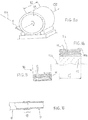
Figures 8a, 8b : tuyau 11 enroulé autour d'un touret de stockage/manutention, suivant deux modes alternatifs d'enroulement, -
Figure 9 : tuyau 11 plié en accordéon dans un conteneur de stockage/manutention, -
Figure 10 :tuyaux 11 aboutés, coaxialement, avec emboîtement longitudinal partiel.
-
Figure 1 : side diagram of the pipe, -
Figure 2 filamentary reinforcements of the knitted, braided, woven ornon-woven base 2 of the coatedwaterproof fabric structure 1 of the pipe, -
Figures 3a, 3b : sections III-III of the pipe of thefigure 1 , in states respectively overwritten on itself and under pressure (at round); the reinforcing threads are not illustrated, -
Figure 4 : side diagram of the pipe, with its different concentric layers and the possible central chuck of manufacture, -
Figures 5a, 5b partial sections respectively, in perspective and section, of the sealedtextile structure 1 coated with the pipe, -
Figure 6 : section in longitudinal section of thepipe 11, -
Figure 7 filamentary reinforcements of the knitted, braided, woven or non-woven base 50 of the reinforcinglayers 5a, 5b of the pipe, -
Figures 8a, 8b :pipe 11 wound around a storage / handling drum, according to two alternative winding modes, -
Figure 9 :pipe 11 folded accordion in a storage / handling container, -
Figure 10 :hoses 11 butted, coaxially, with partial longitudinal interlocking.
La paroi 10 de section fermée du tuyau 11 présente une structure textile étanche enduite 1 constituée d'une base tricotée, tressée, tissée ou non-tissée 2, incorporant des fils longitudinaux de renfort 3 (voir
Pour sa fabrication, on recommande que la structure textile étanche enduite 1 soit réalisée à plat, en bande, puis conformée en tube et thermo-soudée longitudinalement. Il y aura alors favorablement recouvrement 111 des bords (longitudinaux) selon au moins une génératrice ; voir
Autour, cette structure textile étanche enduite, est renforcée par l'application de deux, ou plus de deux, couches telles 5a, 5b constituées chacune de bandes de renfort appliquées en hélices croisées (S et Z) à un angle spécifié; voir
Les bandes de renfort 5a, 5b sont constituées de fils de renfort hélicoïdaux 8 de haute ténacité noyés dans une matrice 9 constituée du même matériau thermoplastique que celui de la structure textile étanche 4 ou d'un matériau thermoplastique compatible avec celui-ci pour être fusionné avec lui ; voir
On conseille que les bandes de renfort 5a, 5b soient fixées sur (autour de) la structure textile étanche enduite 1 par thermo-soudure, de manière à provoquer la fusion des matériaux thermoplastiques 4 et 9 des surfaces en contact et former ainsi une structure tubulaire renforcée par des fils à haute ténacité selon des hélices croisées. L'angle des hélices est mesuré entre la direction de la bande de renfort et la direction perpendiculaire à l'axe du tube.It is advisable that the reinforcing
Le choix pertinent des matériaux thermoplastiques 4 et 9 de la structure textile étanche enduite et des fils de renfort 3,8 permet de réaliser un assemblage des différents éléments, par fusion des couches en contact, sans que les constituants 1, 2, 3, 4, 8 ne soient affectés chimiquement ou mécaniquement.The relevant choice of
Le choix judicieux des différents paramètres géométriques permet de constituer une structure résistante à une pression interne spécifiée et à une tension axiale pure spécifiée sans augmenter la quantité de fils de renforts nécessaires par rapport au seul cas de résistance à la pression interne.The judicious choice of the various geometrical parameters makes it possible to constitute a structure that is resistant to a specified internal pressure and to a specified pure axial tension without increasing the quantity of reinforcement threads required with respect to the single case of resistance to internal pressure.
Au sein de chaque structure textile, les fils de renfort 3,8 comprendront de préférence, pour l'équilibre et la maîtrise des contraintes, des fils de chaine et de trame, respectivement 30,31 et 80,81 ; cf.
Jusqu'à une différence de pressions entre l'intérieur (Pi) et l'extérieur (Pe) du tuyau 11 de 30 bars (30x105 Pa), une structure du type qui précède est susceptible de collapser (s'écraser sur elle-même, en section ; cf.
Précisément, le collapse est un flambement de la paroi au sens de la résistance des matériaux et dépend essentiellement de la géométrie et des modules d'élasticité des matériaux employés. On constate généralement que la résistance au collapse requiert nettement plus de matière pour la résistance externe du tuyau que pour la résistance à la pression interne (Pi).Precisely, the collapse is a buckling of the wall in the sense of the resistance of the materials and depends essentially on the geometry and the moduli of elasticity of the materials used. It is generally found that the collapse resistance requires significantly more material for external resistance of the pipe than for resistance to internal pressure (Pi).
La structure retenue permet d'envisager une production continue, et non plus discrète, et autorise de grandes longueurs de tuyau flexible d'un seul tenant, de 500 mètre à plusieurs kilomètres selon le diamètre et la pression de service et les conditions retenues pour le transport du produit.The structure adopted makes it possible to envisage continuous production, and no longer discrete, and allows long lengths of flexible pipe in one piece, from 500 meters to several kilometers depending on the diameter and the operating pressure and the conditions selected for the transport of the product.
Pour une facilité de manutention lors des transports terrestres et lors de l'installation en mer on recommande une longueur de tuyau d'un seul tenant compris entre 300 et 700 mètres.For ease of handling during land transport and when installing at sea, it is recommended to have a single pipe length of between 300 and 700 meters.
Pour cela, le tube passe autour d'un mandrin circulaire 12 (
Selon ce processus de fabrication, le tuyau 11 conserve son orientation sur le mandrin tout en avançant sur son axe. Les bobines qui délivrent les bandes de renfort sont disposées sur un support qui tourne autour de l'axe du tuyau. De ce fait la production peut être affranchie de la nécessité de faire tourner le tube sur son axe pendant l'application des bandes de renfort, et permet de s'affranchir des limitations de longueurs correspondantes.According to this manufacturing process, the
Le tuyau flexible 11 de grande longueur faisant l'objet de la présente invention peut être utilisé comme une canalisation conventionnelle entre les points de départ et d'arrivée du transport d'un fluide déterminé. Ce tuyau flexible peut être placé à l'air libre, posée sur une fondation ou plongé dans un fluide (typiquement eau de mer) à une pression inférieure à la pression de fonctionnement de la canalisation, maintenant ainsi sa section circulaire. Selon la masse volumique du fluide extérieur, la canalisation est posée sur ou retenue par sa fondation.The
Le tuyau 11 est susceptible d'être appliqué de manière industrielle au transport d'eau douce en milieu marin. Dans le cas où on désire transporter de l'eau depuis une prise d'eau située sur terre entre deux points d'une côte marine, ce tuyau flexible de grande longueur peut être installé sur le fond marin avec un système de fondations adéquat permettant de résister aux efforts hydrodynamiques et sismiques et permettant ainsi le transport de grandes quantités d'eau douce entre deux zones.The
Est aussi possible le transfert d'eau douce interbassins par canaux terrestres, afin d'éviter des pertes importantes liées à l'infiltration dans le sol et à l'évaporation de la surface libre exposée à ciel ouvert dans des régions chaudes et arides où l'évaporation est élevée. Le tuyau flexible 11 peut alors aussi être inséré dans le fond d'un de ces canaux, pour permettre de transporter de l'eau sans exposer sa surface libre, ce qui évite toute évaporation ou infiltration durant le transport.It is also possible to transfer interbasin freshwater via terrestrial channels, in order to avoid significant losses due to infiltration into the soil and evaporation of the exposed open surface in hot and humid areas. arid where evaporation is high. The
Comme illustré, le tuyau 11 obtenu est donc allongé suivant l'axe 110, flexible et apte au transport d'eau douce.As illustrated, the
Il peut donc être enroulé longitudinalement sur un touret ou plié de préférence en accordéon dans un conteneur.It can therefore be wound longitudinally on a drum or folded preferably accordion in a container.
Il est longitudinalement continu et de section circulaire lorsqu'il est mis sous une pression différentielle positive entre l'intérieur et l'extérieur, sa section fermée pouvant s'écraser sur elle-même sous l'effet d'une pression différentielle négative.It is longitudinally continuous and of circular section when it is put under a positive differential pressure between the inside and the outside, its closed section being able to collapse on itself under the effect of a negative differential pressure.
Comme caractéristiques notoires, on a déjà noté :
- un diamètre extérieur D1 compris entre 1 et 7 mètres et une longueur (continue) L1 comprise entre 200 et 3000 mètres,
- une enveloppe 1 (appelée ci-avant structure textile enduite) étanche vis-à-vis du liquide transporté ainsi qu'au moins deux éléments de renfort périphériques (bandes de renfort 5a, 5b étanches ou non à l'eau), accroissant la résistance mécanique du tuyau à une pression différentielle positive (surpression extérieure en immersion) et qui supporte sans éclater ou se fendre une pression différentielle
positive de 1 à au moins 10 bars (10 x 105 Pa).
- an outside diameter D1 of between 1 and 7 meters and a length (continuous) L1 of between 200 and 3000 meters,
- an envelope 1 (hereinafter referred to as a coated textile structure) that is impermeable with respect to the liquid transported as well as at least two peripheral reinforcing elements (reinforcing
strips 5a, 5b that are watertight or non-waterproof), increasing the resistance mechanics of the pipe at a positive differential pressure (external immersion pressure) and which withstand without cracking or splitting a positive differential pressure of 1 to at least 10 bar (10 x 10 5 Pa).
Compte tenu de la fabrication conseillée, l'enveloppe 1 et les éléments de renfort 5a,5b seront donc favorablement en au moins un matériau thermoplastique tel que des plastomères de polyoléfines, de préférence de type LLDPE, métallocènes de chaines à 8 carbones ou des plastomères polyuréthanes ou encore « des nano-crystal structure controlled elastomer » (élastomères à structure nanocristalline contrôlée), renforcé par les fils 3,8, de telle sorte que le tuyau présentera donc favorablement, en section, de l'intérieur vers l'extérieur, au sein du matériau thermoplastique :
- une première nappe textile à structure tricotée, tressée, tissée ou non-tissée 2, ayant des fils longitudinaux 30 parallèles à l'axe longitudinal 110 du tuyau, puis, autour de cette première nappe textile (1) et au sein du matériau thermoplastique (le même ou un autre intimement lié au premier, typiquement par fusion),
- au moins une deuxième puis une troisième nappes textiles enduites,
respectivement 5a, 5b, chacune :- * à structure tricotée, tressée, tissée, non-tissée ou unidirectionnelle 50,
- * enroulée longitudinalement en hélice, le long de l'axe du tuyau, et,
- *présentant les fils longitudinaux 8 parallèles à la génératrice de l'hélice.
- a first textile ply having a knitted, braided, woven or
non-woven structure 2, havinglongitudinal threads 30 parallel to thelongitudinal axis 110 of the pipe, then, around this first textile ply (1) and within the thermoplastic material ( the same or another closely related to the first, typically by fusion), - at least a second and a third coated textile ply, respectively 5a, 5b, each:
- * with knitted, braided, woven, non-woven or unidirectional structure 50,
- * rolled longitudinally helically, along the axis of the pipe, and,
- * presenting the longitudinal son 8 parallel to the generatrix of the propeller.
Si elle existe, la zone 111 de recouvrement du matériau thermoplastique par lui-même réalisée lors de la mise au rond de la bande initiale de matière sera donc formée sensiblement à l'endroit du diamètre du tuyau (voir zone ou portion radiale 112,
Pour un compromis entre flexibilité, résistance à la pression et débit, le diamètre D1 sera favorablement compris entre 1 et 5 mètres.For a compromise between flexibility, resistance to pressure and flow, the diameter D1 will be favorably between 1 and 5 meters.
Quant à la longueur L1, on la recommande donc comprise entre 300 et 1000 mètres. La technique de fabrication par enroulement autour d'un mandrin central l'autorise.As for the length L1, it is recommended between 300 and 1000 meters. The technique of manufacturing by winding around a central mandrel authorizes it.
Pour allier résistance mécanique/vitesse de fabrication/poids limité, on conseille en outre que, sur ce tuyau :
- le titre des fils longitudinaux 3,8 soit compris entre 200 et 8500 Tex,
- et le nombre de ces fils longitudinaux soit inférieur à trois fils par cm.
- the title of the longitudinal threads 3.8 is between 200 and 8500 Tex,
- and the number of these longitudinal threads is less than three threads per cm.
Et la tenue à la pression que l'on doit atteindre en service, pour une immersion sous-marine possible à plus de 100 mètres, invite, pour assurer une intégrité physique du tuyau, sans éclatement, à ce que le tuyau tienne jusqu'à une pression d'éclatement comprise entre 20 et 30 x 105 Pa, de préférence.And the resistance to pressure that must be reached in service, for a submarine immersion possible to more than 100 meters, invites, to ensure a physical integrity of the pipe, without bursting, so that the pipe holds up to a burst pressure of between 20 and 30 x 10 5 Pa, preferably.
Compte tenu de ces conditions opérationnelles de pose en milieu sous-marin, avec courbure longitudinale et /ou latérales à prévoir, on recommande que la masse par mètre linéaire de la paroi 10 du tuyau 11 soit comprise entre 14 kg/ml et 320 kg/ml, selon le diamètre et la pression d'éclatement, et de préférence 14 Kg/ml et 175 Kg/ml.In view of these operational conditions for laying in an underwater environment, with longitudinal and / or lateral curvature to be provided, it is recommended that the mass per linear meter of the
On recommande aussi que la paroi tubulaire 10 ait une épaisseur E (
Pour la tenue mécanique opérationnelle, il est aussi conseillé que la paroi 10 respecte l'inégalité suivante : ![]()
- T : tension axiale de rupture sous pression différentielle (Pi-Pe) nulle,
- P : pression différentielle (Pi-Pe) d'éclatement, avec donc Pi : pression interne du tuyau et Pe : pression externe ;
- R : rayon interne R1 (
figure 3b ) du tuyau sous pression différentielle positive (pression interne supérieure à la pression extérieure) .
- T: axial stress rupture tension under zero differential pressure (Pi-Pe),
- P: differential pressure (Pi-Pe) of burst, with Pi: internal pressure of the pipe and Pe: external pressure;
- R: inner radius R1 (
figure 3b ) of the positive differential pressure pipe (internal pressure greater than the external pressure).
Le respect de tout ou partie des caractéristiques techniques de ce tuyau vise à ce qu'il soit, sans être affecté dans ses fonctionnalités, pression d'éclatement et tension de rupture axiale sous pression différentielle nulle :
- déformable entre une section interne circulaire et une section interne aplatie où deux zones opposées du périmètre interne se touchent,
- et pliable sur lui-même longitudinalement suivant un ruban aplati présentant, à l'endroit des pliures, un rayon de courbure inférieur ou égal à 50 cm,
sans que la pression d'éclatement ni la tension de rupture axiale sous pression différentielle nulle du tuyau soient modifiées de plus de 5%:- ni par le passage de la section interne circulaire à la section interne aplatie et inversement,
- ni par le pliage sur lui-même longitudinalement du tuyau, suivant ledit ruban aplati, et son dépliage à plat.
- deformable between a circular internal section and a flattened internal section where two opposite zones of the internal perimeter touch each other,
- and foldable on itself longitudinally following a flattened ribbon having, at the folds, a radius of curvature less than or equal to 50 cm,
without the bursting pressure or the axial rupture stress under zero differential pressure of the pipe being changed by more than 5%:- neither by the passage of the circular inner section to the flattened internal section and conversely,
- nor by folding itself longitudinally of the pipe, along said flattened ribbon, and unfolding it flat.
Pour limiter l'encombrement, on pourra toutefois préférer que les côtés longitudinaux 11a, 11b du tuyau 11 vide, (sensiblement) aplati pour son stockage, soient rabattus l'un vers l'autre, en portefeuille, comme montré
Pour enrouler ou dérouler le tuyau, le touret tourne sur lui-même autour d'un axe 150 perpendiculaire à l'axe 110 longitudinal du tuyau.To wind or unwind the pipe, the drum turns on itself about an
Quant à la
Au titre des avantages ou problèmes résolus par le tuyau ci-avant présenté et considéré dans tout ou partie de ses caractéristiques, on relèvera encore ce qui suit :
- le tuyau 11 est un tuyau de grand diamètre,
- il peut être fabriqué dans des diamètres jusque-là jamais atteints (4 mètres et plus)
- il peut être fabriqué, avec des épaisseurs de paroi périphérique et des coûts raisonnables, pour résister à des surpressions internes allant jusqu'à 30 x 105 Pa,
- il est en produits composites, flexible et écrasable sur lui-même sans dommage.
- the
pipe 11 is a large diameter pipe, - it can be manufactured in diameters hitherto never reached (4 meters and more)
- it can be manufactured with peripheral wall thicknesses and reasonable costs to withstand internal overpressures of up to 30 x 10 5 Pa,
- it is in composite products, flexible and crushable on itself without damage.
Du fait de cette dernière propriété il est possible de transporter le tuyau vers le site d'installation sous un volume réduit, ce qui réduit les coûts de transport.Because of this latter property it is possible to transport the pipe to the installation site in a reduced volume, which reduces transport costs.
Par ailleurs, plus globalement :
- le tuyau inséré dans un système de transport d'eau (canal, conduite rigide ...) ne souffrira pas d'un coup de bélier négatif, engendré par un arrêt intempestif de la pompe d'expédition (qui fait circuler le liquide dans le tuyau), alors qu'un tube à section rigide risque de s'écraser sur lui-même de façon plastique, voire destructive, entrainant donc des dommages irréparables à sa structure. Pour résister à un coup de bélier négatif, un tube à section rigide doit employer des épaisseurs de matériau incompatibles avec l'économie d'un projet de transport d'eau douce,
- la longueur à poser des tuyaux de transport d'eau douce se chiffre en centaines voire milliers de kilomètres. Pour installer de telles canalisations dans des délais raisonnables, le tuyau doit être fabriqué à une cadence très élevée, de 5 à 10 km/jour. La structure en hélice multicouches permet de répartir la production des composants de l'assemblage sur différents sites de production des composants et réduit la durée de la phase d'assemblage, tout en ayant l'assurance d'un tenue mécanique appropriée (voir ci-avant),
- pour poser le tuyau en mer dans des délais raisonnables, il faut minimiser le nombre de soudures à réaliser sur le chantier, en mer, sur le (s) navire(s). La grande longueur élémentaire de chaque segment fabriqué permet de constituer des longueurs de plusieurs segments à bord du bateau d'installation et permet de réduire ce nombre de soudures et d'accélérer la cadence de pose jusqu'à des valeurs de 6 à 8 km/jour pour un tube de 4m de diamètre. Il en résulte un rythme d'installation élevé par comparaison avec les techniques de pose existantes (typiquement une dizaine de mètres).
- the pipe inserted in a water transport system (canal, rigid pipe ...) will not suffer a blow from negative ram, caused by an inadvertent shutdown of the shipping pump (which circulates the liquid in the pipe), whereas a rigid section tube may collapse on itself in a plastic or even destructive way, causing therefore irreparable damage to its structure. To resist a negative water hammer, a rigid section pipe must use material thicknesses that are incompatible with the economics of a freshwater transport project.
- the length of laying of freshwater transport pipes is hundreds or even thousands of kilometers. To install such pipelines within a reasonable time, the pipe must be manufactured at a very high rate of 5 to 10 km / day. The multi-layer helix structure distributes the production of the components of the assembly to different production sites of the components and reduces the duration of the assembly phase, while having the assurance of an appropriate mechanical strength (see below). before),
- to lay the pipe at sea within a reasonable time, it is necessary to minimize the number of welds to be made on the shipyard, at sea, on the ship (s). The long elementary length of each manufactured segment makes it possible to form lengths of several segments aboard the installation boat and makes it possible to reduce this number of welds and to accelerate the rate of laying to values of 6 to 8 km / day for a tube of 4m in diameter. This results in a high installation rate compared to existing installation techniques (typically about ten meters).
Claims (14)
- Flexible pipe elongate along an axis, adapted to transport fresh water, able to be wound longitudinally on a drum (15) or folded in a container (16), longitudinally continuous, of circular section when there is a positive differential pressure between the interior of the pipe and the exterior, the section of which can be crushed on itself by the effect of a negative differential pressure, the pipe having an outside diameter (D1) between 1 and 7 metres inclusive and comprising an envelope (1) impermeable to the transported liquid, characterized in that it has a length (L1) between 200 and 3000 metres inclusive and comprises at least two peripheral reinforcing elements (5a, 5b) increasing the mechanical strength of the pipe relative to a positive differential pressure and the pipe withstands without bursting or splitting a positive differential pressure from 1 to at least 10 x 105 Pa,
characterized in that the envelope and the reinforcing elements (5a, 5b) are made from at least one thermoplastic material reinforced with filaments (3,8) so that the pipe includes, in section, from the interior toward the exterior, within the thermoplastic material:- a first textile layer (1) of knitted, braided, woven or non-woven structure (2), having longitudinal filaments (30) parallel to the longitudinal axis (110) of the pipe, then, around said first textile layer (1),- at least one second then one third textile layers (5a, 5b) each:* of knitted, braided, woven, non-woven or unidirectional structure (2),* wound longitudinally in a helix along the axis (110) of the pipe, and* including longitudinal filaments (80) parallel to the generatrix of the helix. - Pipe according to Claim 1 or 2 having a diameter (D1) between 1 and 5 metres inclusive.
- Length of a pipe according to any one of the preceding claims having a length (L1) between 300 and 1000 metres inclusive.
- Pipe according to any one of the preceding claims, having a mass per linear metre between 14 kg/ml and 320 kg/ml inclusive depending on the diameter and the bursting pressure.
- Pipe according to any one of the preceding claims, having a tubular wall (10) with a thickness (E) between 6 and 17 millimetres inclusive depending on the diameter and the bursting pressure.
- Pipe according to any one of the preceding claims, respecting the following inequality:

 T: axial breaking tension at zero differential pressure,P: bursting differential pressure between the interior and the exterior of the pipe,R: inside radius of the pipe under positive differential pressure.
 - Pipe according to any one of the preceding claims, having a bursting pressure between 3 and 30 x 105 Pa inclusive.
- Pipe according to any one of the preceding claims, which is:- deformable between a circular internal section and a flattened internal section in which two opposite zones of the internal perimeter touch each other, and- foldable on itself longitudinally to form a flattened strip having, at the location of the folds, a radius of curvature less than or equal to 50 cm,without the bursting pressure or the axial breaking tension under zero differential pressure of the pipe being modified more than 5%,• by the passage from the circular internal section to the flattened internal section and vice versa, and• by the folding of the pipe longitudinally on itself to form said flattened strip and unfolding it flat.
- Pipe according to Claim 2, or said Claim 2 and any one of the preceding Claims 3 to 9, wherein:- the denier of the longitudinal filaments (3,8) is between 200 and 8500 Tex inclusive, and- the number of longitudinal filaments is less than three filaments per cm.
- Pipe according to any one of Claims 1 to 10, wherein, substantially at the location of the diameter (112) at which the first textile layer (1) is situated, the first textile layer includes a zone (111) in which said thermoplastic material is overlapped on itself.
- System comprising:- a length of the pipe (11) according to any one of Claims 1 to 10, and- a drum (15) around which said length is wound, flat or in a state immediately close to such a flat state, not folded on itself perpendicularly to its longitudinal axis, the drum having a width (12) oriented perpendicularly to the longitudinal axis (110) of said length of pipe, this width being greater than the half-perimeter of the pipe in a circular state of the section of this pipe.
- System comprising:- a length of the pipe (11) according to any one of Claims 1 to 10, and- a drum (15) around which said length is wound, with its section flattened, folded on itself perpendicularly to its longitudinal axis (110), the drum having a width (12) oriented perpendicularly to the longitudinal axis of said length of pipe, this width being less than the half-perimeter of the pipe in a circular state of the section of this pipe.
- System comprising:- a length of the pipe (11) according to any one of Claims 1 to 11, and- a container (16) in which the pipe is accordion-folded.
- Assembly of a plurality of pipes according to any one of Claims 1 to 10, butt-jointed two by two at the location of a welding zone (17) where at least some of the aforementioned thermoplastic materials of the pipes (11) are fused.
Applications Claiming Priority (2)
| Application Number | Priority Date | Filing Date | Title |
|---|---|---|---|
| FR1354614A FR3006028B1 (en) | 2013-05-22 | 2013-05-22 | FLEXIBLE PIPE FOR THE TRANSPORT OF FRESHWATER, TOGETHER FOR ITS STORAGE AND ASSEMBLY OF SEVERAL PIPES. |
| PCT/FR2014/050877 WO2014188095A1 (en) | 2013-05-22 | 2014-04-10 | Flexible pipe for transporting fresh water, set for the storage thereof and assembly of a plurality of pipes |
Publications (2)
| Publication Number | Publication Date |
|---|---|
| EP2999584A1 EP2999584A1 (en) | 2016-03-30 |
| EP2999584B1 true EP2999584B1 (en) | 2019-07-03 |
Family
ID=49111373
Family Applications (1)
| Application Number | Title | Priority Date | Filing Date |
|---|---|---|---|
| EP14726396.6A Active EP2999584B1 (en) | 2013-05-22 | 2014-04-10 | Flexible pipe for transporting fresh water, set for the storage thereof and assembly of a plurality of pipes |
Country Status (7)
| Country | Link |
|---|---|
| US (1) | US9945500B2 (en) |
| EP (1) | EP2999584B1 (en) |
| CL (1) | CL2015003439A1 (en) |
| FR (1) | FR3006028B1 (en) |
| MA (1) | MA38607B1 (en) |
| TN (1) | TN2015000509A1 (en) |
| WO (1) | WO2014188095A1 (en) |
Families Citing this family (1)
| Publication number | Priority date | Publication date | Assignee | Title |
|---|---|---|---|---|
| EP3663508B1 (en) | 2018-12-04 | 2022-04-20 | Sandvik Mining and Construction Oy | Apparatus for feeding tube elements, rock drilling rig and method of supporting drill hole openings |
Citations (1)
| Publication number | Priority date | Publication date | Assignee | Title |
|---|---|---|---|---|
| FR2194906A1 (en) * | 1972-07-31 | 1974-03-01 | Goodyear Tire & Rubber |
Family Cites Families (16)
| Publication number | Priority date | Publication date | Assignee | Title |
|---|---|---|---|---|
| US1053933A (en) * | 1911-02-18 | 1913-02-18 | Benjamin L Stowe | Rubber-lined fabric hose. |
| US1100829A (en) * | 1911-04-07 | 1914-06-23 | Goodrich Co B F | Hose construction. |
| US3374806A (en) * | 1965-02-10 | 1968-03-26 | Hewitt Robins Inc | Submarine hose |
| US3467013A (en) * | 1965-05-14 | 1969-09-16 | Jack S Conner | Submarine fluid transmission system and conduit therefor |
| US3915618A (en) * | 1972-02-10 | 1975-10-28 | Goodyear Tire & Rubber | Apparatus for making hose |
| JPS5094519A (en) * | 1973-12-13 | 1975-07-28 | ||
| US3918782A (en) * | 1974-05-23 | 1975-11-11 | Thomas R Allmand | Fire hose cabinet |
| FR2606487B1 (en) * | 1986-11-07 | 1989-03-10 | Silix | POLYOLEFINIC RESIN TUBES FOR THE PRODUCTION OF PIPES, SLEEVES FOR THEIR ASSEMBLY AND METHOD FOR THEIR MANUFACTURE |
| GB9106297D0 (en) * | 1991-03-25 | 1991-05-08 | British Petroleum Co Plc | Method of transporting fluids |
| GB2327997B (en) * | 1997-07-31 | 2002-09-25 | Raymond Lippiatt | Method and apparatus for deforming a pipe liner |
| FR2786246B1 (en) * | 1998-11-19 | 2001-02-09 | Felix Bogliolo | PIPE FOR TRANSPORTING LIQUID IN A MARINE ENVIRONMENT AND MANUFACTURING METHOD THEREOF |
| WO2003081105A1 (en) * | 2002-03-27 | 2003-10-02 | Pinheiro Torggler Sergio | A flexible duct for transporting fluids, and use of a flexible duct for transportating fluids |
| US6926037B2 (en) * | 2002-12-17 | 2005-08-09 | Wellstream International Limited | Collapse tolerant flexible pipe and method of manufacturing same |
| WO2009125330A2 (en) * | 2008-04-10 | 2009-10-15 | Aisapack Holding S.A. | Method for manufacturing tubes by welding |
| MX342319B (en) * | 2010-11-16 | 2016-09-26 | Tetra Tech | Rapid deployment frac water transfer system. |
| FR2983933B1 (en) | 2011-12-07 | 2014-02-07 | Via Marina | ASSEMBLY FOR UNDERWATER INSTALLATION OF A FLEXIBLE AND DEFORMABLE LIQUID TRANSPORT HOSE, AND ASSOCIATED FLOATING STRUCTURE |
-
2013
- 2013-05-22 FR FR1354614A patent/FR3006028B1/en not_active Expired - Fee Related
-
2014
- 2014-04-10 WO PCT/FR2014/050877 patent/WO2014188095A1/en active Application Filing
- 2014-04-10 EP EP14726396.6A patent/EP2999584B1/en active Active
- 2014-04-10 US US14/892,905 patent/US9945500B2/en active Active
- 2014-04-10 TN TN2015000509A patent/TN2015000509A1/en unknown
- 2014-04-10 MA MA38607A patent/MA38607B1/en unknown
-
2015
- 2015-11-23 CL CL2015003439A patent/CL2015003439A1/en unknown
Patent Citations (1)
| Publication number | Priority date | Publication date | Assignee | Title |
|---|---|---|---|---|
| FR2194906A1 (en) * | 1972-07-31 | 1974-03-01 | Goodyear Tire & Rubber |
Also Published As
| Publication number | Publication date |
|---|---|
| US20160109041A1 (en) | 2016-04-21 |
| CL2015003439A1 (en) | 2016-10-14 |
| US9945500B2 (en) | 2018-04-17 |
| MA38607B1 (en) | 2017-11-30 |
| WO2014188095A1 (en) | 2014-11-27 |
| FR3006028B1 (en) | 2015-12-25 |
| EP2999584A1 (en) | 2016-03-30 |
| FR3006028A1 (en) | 2014-11-28 |
| MA38607A1 (en) | 2016-12-30 |
| TN2015000509A1 (en) | 2016-06-29 |
Similar Documents
| Publication | Publication Date | Title |
|---|---|---|
| EP3140584B1 (en) | Unbonded flexible pipe for transporting an abrasive material, associated method and associated use | |
| EP0494299B1 (en) | Casing and flexible tubular duct comprising same | |
| US8720066B2 (en) | Hose | |
| EP0877887B1 (en) | Flexible pipe with internal gasproof undulating metal tube | |
| US8713797B2 (en) | Hose | |
| EP1165997B1 (en) | Radial partition device, in particular radial buckle arrestor for a double-walled deep water pipeline | |
| EP0527932A1 (en) | Preform device and process for coating and/or lining a cylindrical volume | |
| WO1986007432A1 (en) | Conduit usable particularly for transporting fluids and enabling to limit the permeability to transported fluids | |
| EP1159556B1 (en) | Method and installation for laying a cylindrical pipe on a support | |
| OA12749A (en) | Flexible pipe flattenable. | |
| EP2999584B1 (en) | Flexible pipe for transporting fresh water, set for the storage thereof and assembly of a plurality of pipes | |
| EP0372041B1 (en) | Flexible tube comprising an aluminium alloy | |
| WO2003036151A1 (en) | Highly flexible multistructure tube | |
| WO2012072894A1 (en) | Paid-out rigid pipe with polymer sheath and method of manufacturing the paid-out rigid pipe | |
| WO2013083927A1 (en) | Implementation of a fluid transportation pipe with flexible hold | |
| WO2022096748A1 (en) | Flexible fluid transport pipe and associated methods | |
| EP2917628B1 (en) | Flexible pipe for transporting a cryogenic fluid, and associated installation and method | |
| FR2786246A1 (en) | Flexible tubing for the transport of a liquid along the seabed and its process of fabrication as it is laid | |
| EP3408571B1 (en) | Flexible line with flooded annular space | |
| EP1855040A1 (en) | Improvements relating to hose | |
| FR2835584A1 (en) | Hollow cylindrical pipe or reservoir made from spiral wound reinforced thermoplastic strip with edges welded together | |
| WO2000043587A1 (en) | Method for making a composite tether for an offshore platform, and tether obtainable by said method |
Legal Events
| Date | Code | Title | Description |
|---|---|---|---|
| PUAI | Public reference made under article 153(3) epc to a published international application that has entered the european phase |
Free format text: ORIGINAL CODE: 0009012 |
|
| 17P | Request for examination filed |
Effective date: 20151119 |
|
| AK | Designated contracting states |
Kind code of ref document: A1 Designated state(s): AL AT BE BG CH CY CZ DE DK EE ES FI FR GB GR HR HU IE IS IT LI LT LU LV MC MK MT NL NO PL PT RO RS SE SI SK SM TR |
|
| AX | Request for extension of the european patent |
Extension state: BA ME |
|
| DAX | Request for extension of the european patent (deleted) | ||
| STAA | Information on the status of an ep patent application or granted ep patent |
Free format text: STATUS: EXAMINATION IS IN PROGRESS |
|
| 17Q | First examination report despatched |
Effective date: 20181018 |
|
| GRAP | Despatch of communication of intention to grant a patent |
Free format text: ORIGINAL CODE: EPIDOSNIGR1 |
|
| STAA | Information on the status of an ep patent application or granted ep patent |
Free format text: STATUS: GRANT OF PATENT IS INTENDED |
|
| RIC1 | Information provided on ipc code assigned before grant |
Ipc: F16L 11/04 20060101ALI20190118BHEP Ipc: B29D 23/00 20060101AFI20190118BHEP Ipc: B32B 5/02 20060101ALI20190118BHEP Ipc: E21B 43/01 20060101ALI20190118BHEP Ipc: F16L 57/02 20060101ALI20190118BHEP Ipc: B32B 1/08 20060101ALI20190118BHEP Ipc: F16L 11/08 20060101ALI20190118BHEP Ipc: B32B 5/26 20060101ALI20190118BHEP Ipc: B32B 5/10 20060101ALI20190118BHEP Ipc: F16L 47/02 20060101ALI20190118BHEP Ipc: B32B 5/12 20060101ALI20190118BHEP Ipc: B32B 27/08 20060101ALI20190118BHEP Ipc: F16L 11/02 20060101ALI20190118BHEP |
|
| INTG | Intention to grant announced |
Effective date: 20190227 |
|
| GRAS | Grant fee paid |
Free format text: ORIGINAL CODE: EPIDOSNIGR3 |
|
| GRAA | (expected) grant |
Free format text: ORIGINAL CODE: 0009210 |
|
| STAA | Information on the status of an ep patent application or granted ep patent |
Free format text: STATUS: THE PATENT HAS BEEN GRANTED |
|
| AK | Designated contracting states |
Kind code of ref document: B1 Designated state(s): AL AT BE BG CH CY CZ DE DK EE ES FI FR GB GR HR HU IE IS IT LI LT LU LV MC MK MT NL NO PL PT RO RS SE SI SK SM TR |
|
| REG | Reference to a national code |
Ref country code: GB Ref legal event code: FG4D Free format text: NOT ENGLISH |
|
| REG | Reference to a national code |
Ref country code: CH Ref legal event code: EP Ref country code: AT Ref legal event code: REF Ref document number: 1150457 Country of ref document: AT Kind code of ref document: T Effective date: 20190715 |
|
| REG | Reference to a national code |
Ref country code: IE Ref legal event code: FG4D Free format text: LANGUAGE OF EP DOCUMENT: FRENCH |
|
| REG | Reference to a national code |
Ref country code: DE Ref legal event code: R096 Ref document number: 602014049446 Country of ref document: DE |
|
| REG | Reference to a national code |
Ref country code: NL Ref legal event code: MP Effective date: 20190703 |
|
| REG | Reference to a national code |
Ref country code: LT Ref legal event code: MG4D |
|
| REG | Reference to a national code |
Ref country code: AT Ref legal event code: MK05 Ref document number: 1150457 Country of ref document: AT Kind code of ref document: T Effective date: 20190703 |
|
| PG25 | Lapsed in a contracting state [announced via postgrant information from national office to epo] |
Ref country code: FI Free format text: LAPSE BECAUSE OF FAILURE TO SUBMIT A TRANSLATION OF THE DESCRIPTION OR TO PAY THE FEE WITHIN THE PRESCRIBED TIME-LIMIT Effective date: 20190703 Ref country code: BG Free format text: LAPSE BECAUSE OF FAILURE TO SUBMIT A TRANSLATION OF THE DESCRIPTION OR TO PAY THE FEE WITHIN THE PRESCRIBED TIME-LIMIT Effective date: 20191003 Ref country code: SE Free format text: LAPSE BECAUSE OF FAILURE TO SUBMIT A TRANSLATION OF THE DESCRIPTION OR TO PAY THE FEE WITHIN THE PRESCRIBED TIME-LIMIT Effective date: 20190703 Ref country code: NO Free format text: LAPSE BECAUSE OF FAILURE TO SUBMIT A TRANSLATION OF THE DESCRIPTION OR TO PAY THE FEE WITHIN THE PRESCRIBED TIME-LIMIT Effective date: 20191003 Ref country code: AT Free format text: LAPSE BECAUSE OF FAILURE TO SUBMIT A TRANSLATION OF THE DESCRIPTION OR TO PAY THE FEE WITHIN THE PRESCRIBED TIME-LIMIT Effective date: 20190703 Ref country code: HR Free format text: LAPSE BECAUSE OF FAILURE TO SUBMIT A TRANSLATION OF THE DESCRIPTION OR TO PAY THE FEE WITHIN THE PRESCRIBED TIME-LIMIT Effective date: 20190703 Ref country code: PT Free format text: LAPSE BECAUSE OF FAILURE TO SUBMIT A TRANSLATION OF THE DESCRIPTION OR TO PAY THE FEE WITHIN THE PRESCRIBED TIME-LIMIT Effective date: 20191104 Ref country code: NL Free format text: LAPSE BECAUSE OF FAILURE TO SUBMIT A TRANSLATION OF THE DESCRIPTION OR TO PAY THE FEE WITHIN THE PRESCRIBED TIME-LIMIT Effective date: 20190703 Ref country code: CZ Free format text: LAPSE BECAUSE OF FAILURE TO SUBMIT A TRANSLATION OF THE DESCRIPTION OR TO PAY THE FEE WITHIN THE PRESCRIBED TIME-LIMIT Effective date: 20190703 Ref country code: LT Free format text: LAPSE BECAUSE OF FAILURE TO SUBMIT A TRANSLATION OF THE DESCRIPTION OR TO PAY THE FEE WITHIN THE PRESCRIBED TIME-LIMIT Effective date: 20190703 |
|
| PG25 | Lapsed in a contracting state [announced via postgrant information from national office to epo] |
Ref country code: RS Free format text: LAPSE BECAUSE OF FAILURE TO SUBMIT A TRANSLATION OF THE DESCRIPTION OR TO PAY THE FEE WITHIN THE PRESCRIBED TIME-LIMIT Effective date: 20190703 Ref country code: LV Free format text: LAPSE BECAUSE OF FAILURE TO SUBMIT A TRANSLATION OF THE DESCRIPTION OR TO PAY THE FEE WITHIN THE PRESCRIBED TIME-LIMIT Effective date: 20190703 Ref country code: ES Free format text: LAPSE BECAUSE OF FAILURE TO SUBMIT A TRANSLATION OF THE DESCRIPTION OR TO PAY THE FEE WITHIN THE PRESCRIBED TIME-LIMIT Effective date: 20190703 Ref country code: GR Free format text: LAPSE BECAUSE OF FAILURE TO SUBMIT A TRANSLATION OF THE DESCRIPTION OR TO PAY THE FEE WITHIN THE PRESCRIBED TIME-LIMIT Effective date: 20191004 Ref country code: IS Free format text: LAPSE BECAUSE OF FAILURE TO SUBMIT A TRANSLATION OF THE DESCRIPTION OR TO PAY THE FEE WITHIN THE PRESCRIBED TIME-LIMIT Effective date: 20191103 |
|
| PG25 | Lapsed in a contracting state [announced via postgrant information from national office to epo] |
Ref country code: TR Free format text: LAPSE BECAUSE OF FAILURE TO SUBMIT A TRANSLATION OF THE DESCRIPTION OR TO PAY THE FEE WITHIN THE PRESCRIBED TIME-LIMIT Effective date: 20190703 |
|
| PG25 | Lapsed in a contracting state [announced via postgrant information from national office to epo] |
Ref country code: PL Free format text: LAPSE BECAUSE OF FAILURE TO SUBMIT A TRANSLATION OF THE DESCRIPTION OR TO PAY THE FEE WITHIN THE PRESCRIBED TIME-LIMIT Effective date: 20190703 Ref country code: IT Free format text: LAPSE BECAUSE OF FAILURE TO SUBMIT A TRANSLATION OF THE DESCRIPTION OR TO PAY THE FEE WITHIN THE PRESCRIBED TIME-LIMIT Effective date: 20190703 Ref country code: RO Free format text: LAPSE BECAUSE OF FAILURE TO SUBMIT A TRANSLATION OF THE DESCRIPTION OR TO PAY THE FEE WITHIN THE PRESCRIBED TIME-LIMIT Effective date: 20190703 Ref country code: DK Free format text: LAPSE BECAUSE OF FAILURE TO SUBMIT A TRANSLATION OF THE DESCRIPTION OR TO PAY THE FEE WITHIN THE PRESCRIBED TIME-LIMIT Effective date: 20190703 Ref country code: EE Free format text: LAPSE BECAUSE OF FAILURE TO SUBMIT A TRANSLATION OF THE DESCRIPTION OR TO PAY THE FEE WITHIN THE PRESCRIBED TIME-LIMIT Effective date: 20190703 |
|
| PG25 | Lapsed in a contracting state [announced via postgrant information from national office to epo] |
Ref country code: SK Free format text: LAPSE BECAUSE OF FAILURE TO SUBMIT A TRANSLATION OF THE DESCRIPTION OR TO PAY THE FEE WITHIN THE PRESCRIBED TIME-LIMIT Effective date: 20190703 Ref country code: SM Free format text: LAPSE BECAUSE OF FAILURE TO SUBMIT A TRANSLATION OF THE DESCRIPTION OR TO PAY THE FEE WITHIN THE PRESCRIBED TIME-LIMIT Effective date: 20190703 Ref country code: IS Free format text: LAPSE BECAUSE OF FAILURE TO SUBMIT A TRANSLATION OF THE DESCRIPTION OR TO PAY THE FEE WITHIN THE PRESCRIBED TIME-LIMIT Effective date: 20200224 |
|
| REG | Reference to a national code |
Ref country code: DE Ref legal event code: R097 Ref document number: 602014049446 Country of ref document: DE |
|
| PLBE | No opposition filed within time limit |
Free format text: ORIGINAL CODE: 0009261 |
|
| STAA | Information on the status of an ep patent application or granted ep patent |
Free format text: STATUS: NO OPPOSITION FILED WITHIN TIME LIMIT |
|
| PG2D | Information on lapse in contracting state deleted |
Ref country code: IS |
|
| 26N | No opposition filed |
Effective date: 20200603 |
|
| PG25 | Lapsed in a contracting state [announced via postgrant information from national office to epo] |
Ref country code: SI Free format text: LAPSE BECAUSE OF FAILURE TO SUBMIT A TRANSLATION OF THE DESCRIPTION OR TO PAY THE FEE WITHIN THE PRESCRIBED TIME-LIMIT Effective date: 20190703 |
|
| REG | Reference to a national code |
Ref country code: DE Ref legal event code: R119 Ref document number: 602014049446 Country of ref document: DE |
|
| PG25 | Lapsed in a contracting state [announced via postgrant information from national office to epo] |
Ref country code: MC Free format text: LAPSE BECAUSE OF FAILURE TO SUBMIT A TRANSLATION OF THE DESCRIPTION OR TO PAY THE FEE WITHIN THE PRESCRIBED TIME-LIMIT Effective date: 20190703 |
|
| REG | Reference to a national code |
Ref country code: CH Ref legal event code: PL |
|
| PG25 | Lapsed in a contracting state [announced via postgrant information from national office to epo] |
Ref country code: LU Free format text: LAPSE BECAUSE OF NON-PAYMENT OF DUE FEES Effective date: 20200410 Ref country code: DE Free format text: LAPSE BECAUSE OF NON-PAYMENT OF DUE FEES Effective date: 20201103 Ref country code: LI Free format text: LAPSE BECAUSE OF NON-PAYMENT OF DUE FEES Effective date: 20200430 Ref country code: CH Free format text: LAPSE BECAUSE OF NON-PAYMENT OF DUE FEES Effective date: 20200430 |
|
| REG | Reference to a national code |
Ref country code: BE Ref legal event code: MM Effective date: 20200430 |
|
| PG25 | Lapsed in a contracting state [announced via postgrant information from national office to epo] |
Ref country code: BE Free format text: LAPSE BECAUSE OF NON-PAYMENT OF DUE FEES Effective date: 20200430 |
|
| GBPC | Gb: european patent ceased through non-payment of renewal fee |
Effective date: 20200410 |
|
| PG25 | Lapsed in a contracting state [announced via postgrant information from national office to epo] |
Ref country code: IE Free format text: LAPSE BECAUSE OF NON-PAYMENT OF DUE FEES Effective date: 20200410 Ref country code: GB Free format text: LAPSE BECAUSE OF NON-PAYMENT OF DUE FEES Effective date: 20200410 |
|
| PG25 | Lapsed in a contracting state [announced via postgrant information from national office to epo] |
Ref country code: MT Free format text: LAPSE BECAUSE OF FAILURE TO SUBMIT A TRANSLATION OF THE DESCRIPTION OR TO PAY THE FEE WITHIN THE PRESCRIBED TIME-LIMIT Effective date: 20190703 Ref country code: CY Free format text: LAPSE BECAUSE OF FAILURE TO SUBMIT A TRANSLATION OF THE DESCRIPTION OR TO PAY THE FEE WITHIN THE PRESCRIBED TIME-LIMIT Effective date: 20190703 |
|
| PG25 | Lapsed in a contracting state [announced via postgrant information from national office to epo] |
Ref country code: MK Free format text: LAPSE BECAUSE OF FAILURE TO SUBMIT A TRANSLATION OF THE DESCRIPTION OR TO PAY THE FEE WITHIN THE PRESCRIBED TIME-LIMIT Effective date: 20190703 Ref country code: AL Free format text: LAPSE BECAUSE OF FAILURE TO SUBMIT A TRANSLATION OF THE DESCRIPTION OR TO PAY THE FEE WITHIN THE PRESCRIBED TIME-LIMIT Effective date: 20190703 |
|
| PGFP | Annual fee paid to national office [announced via postgrant information from national office to epo] |
Ref country code: AL Payment date: 20220420 Year of fee payment: 9 |
|
| PGFP | Annual fee paid to national office [announced via postgrant information from national office to epo] |
Ref country code: FR Payment date: 20230424 Year of fee payment: 10 |