EP2999433B1 - Transkatheter-herzklappe für mitral- oder trikuspidklappenersatz - Google Patents
Transkatheter-herzklappe für mitral- oder trikuspidklappenersatz Download PDFInfo
- Publication number
- EP2999433B1 EP2999433B1 EP13885021.9A EP13885021A EP2999433B1 EP 2999433 B1 EP2999433 B1 EP 2999433B1 EP 13885021 A EP13885021 A EP 13885021A EP 2999433 B1 EP2999433 B1 EP 2999433B1
- Authority
- EP
- European Patent Office
- Prior art keywords
- section
- migration
- stent
- inflow
- inflow section
- Prior art date
- Legal status (The legal status is an assumption and is not a legal conclusion. Google has not performed a legal analysis and makes no representation as to the accuracy of the status listed.)
- Active
Links
Images


Classifications
-
- A—HUMAN NECESSITIES
- A61—MEDICAL OR VETERINARY SCIENCE; HYGIENE
- A61F—FILTERS IMPLANTABLE INTO BLOOD VESSELS; PROSTHESES; DEVICES PROVIDING PATENCY TO, OR PREVENTING COLLAPSING OF, TUBULAR STRUCTURES OF THE BODY, e.g. STENTS; ORTHOPAEDIC, NURSING OR CONTRACEPTIVE DEVICES; FOMENTATION; TREATMENT OR PROTECTION OF EYES OR EARS; BANDAGES, DRESSINGS OR ABSORBENT PADS; FIRST-AID KITS
- A61F2/00—Filters implantable into blood vessels; Prostheses, i.e. artificial substitutes or replacements for parts of the body; Appliances for connecting them with the body; Devices providing patency to, or preventing collapsing of, tubular structures of the body, e.g. stents
- A61F2/02—Prostheses implantable into the body
- A61F2/24—Heart valves ; Vascular valves, e.g. venous valves; Heart implants, e.g. passive devices for improving the function of the native valve or the heart muscle; Transmyocardial revascularisation [TMR] devices; Valves implantable in the body
- A61F2/2412—Heart valves ; Vascular valves, e.g. venous valves; Heart implants, e.g. passive devices for improving the function of the native valve or the heart muscle; Transmyocardial revascularisation [TMR] devices; Valves implantable in the body with soft flexible valve members, e.g. tissue valves shaped like natural valves
- A61F2/2418—Scaffolds therefor, e.g. support stents
-
- A—HUMAN NECESSITIES
- A61—MEDICAL OR VETERINARY SCIENCE; HYGIENE
- A61F—FILTERS IMPLANTABLE INTO BLOOD VESSELS; PROSTHESES; DEVICES PROVIDING PATENCY TO, OR PREVENTING COLLAPSING OF, TUBULAR STRUCTURES OF THE BODY, e.g. STENTS; ORTHOPAEDIC, NURSING OR CONTRACEPTIVE DEVICES; FOMENTATION; TREATMENT OR PROTECTION OF EYES OR EARS; BANDAGES, DRESSINGS OR ABSORBENT PADS; FIRST-AID KITS
- A61F2/00—Filters implantable into blood vessels; Prostheses, i.e. artificial substitutes or replacements for parts of the body; Appliances for connecting them with the body; Devices providing patency to, or preventing collapsing of, tubular structures of the body, e.g. stents
- A61F2/02—Prostheses implantable into the body
- A61F2/24—Heart valves ; Vascular valves, e.g. venous valves; Heart implants, e.g. passive devices for improving the function of the native valve or the heart muscle; Transmyocardial revascularisation [TMR] devices; Valves implantable in the body
- A61F2/2412—Heart valves ; Vascular valves, e.g. venous valves; Heart implants, e.g. passive devices for improving the function of the native valve or the heart muscle; Transmyocardial revascularisation [TMR] devices; Valves implantable in the body with soft flexible valve members, e.g. tissue valves shaped like natural valves
-
- A—HUMAN NECESSITIES
- A61—MEDICAL OR VETERINARY SCIENCE; HYGIENE
- A61F—FILTERS IMPLANTABLE INTO BLOOD VESSELS; PROSTHESES; DEVICES PROVIDING PATENCY TO, OR PREVENTING COLLAPSING OF, TUBULAR STRUCTURES OF THE BODY, e.g. STENTS; ORTHOPAEDIC, NURSING OR CONTRACEPTIVE DEVICES; FOMENTATION; TREATMENT OR PROTECTION OF EYES OR EARS; BANDAGES, DRESSINGS OR ABSORBENT PADS; FIRST-AID KITS
- A61F2/00—Filters implantable into blood vessels; Prostheses, i.e. artificial substitutes or replacements for parts of the body; Appliances for connecting them with the body; Devices providing patency to, or preventing collapsing of, tubular structures of the body, e.g. stents
- A61F2/02—Prostheses implantable into the body
- A61F2/24—Heart valves ; Vascular valves, e.g. venous valves; Heart implants, e.g. passive devices for improving the function of the native valve or the heart muscle; Transmyocardial revascularisation [TMR] devices; Valves implantable in the body
- A61F2/2409—Support rings therefor, e.g. for connecting valves to tissue
-
- A—HUMAN NECESSITIES
- A61—MEDICAL OR VETERINARY SCIENCE; HYGIENE
- A61F—FILTERS IMPLANTABLE INTO BLOOD VESSELS; PROSTHESES; DEVICES PROVIDING PATENCY TO, OR PREVENTING COLLAPSING OF, TUBULAR STRUCTURES OF THE BODY, e.g. STENTS; ORTHOPAEDIC, NURSING OR CONTRACEPTIVE DEVICES; FOMENTATION; TREATMENT OR PROTECTION OF EYES OR EARS; BANDAGES, DRESSINGS OR ABSORBENT PADS; FIRST-AID KITS
- A61F2/00—Filters implantable into blood vessels; Prostheses, i.e. artificial substitutes or replacements for parts of the body; Appliances for connecting them with the body; Devices providing patency to, or preventing collapsing of, tubular structures of the body, e.g. stents
- A61F2/02—Prostheses implantable into the body
- A61F2/24—Heart valves ; Vascular valves, e.g. venous valves; Heart implants, e.g. passive devices for improving the function of the native valve or the heart muscle; Transmyocardial revascularisation [TMR] devices; Valves implantable in the body
- A61F2/2427—Devices for manipulating or deploying heart valves during implantation
- A61F2/243—Deployment by mechanical expansion
-
- A—HUMAN NECESSITIES
- A61—MEDICAL OR VETERINARY SCIENCE; HYGIENE
- A61F—FILTERS IMPLANTABLE INTO BLOOD VESSELS; PROSTHESES; DEVICES PROVIDING PATENCY TO, OR PREVENTING COLLAPSING OF, TUBULAR STRUCTURES OF THE BODY, e.g. STENTS; ORTHOPAEDIC, NURSING OR CONTRACEPTIVE DEVICES; FOMENTATION; TREATMENT OR PROTECTION OF EYES OR EARS; BANDAGES, DRESSINGS OR ABSORBENT PADS; FIRST-AID KITS
- A61F2/00—Filters implantable into blood vessels; Prostheses, i.e. artificial substitutes or replacements for parts of the body; Appliances for connecting them with the body; Devices providing patency to, or preventing collapsing of, tubular structures of the body, e.g. stents
- A61F2/02—Prostheses implantable into the body
- A61F2/24—Heart valves ; Vascular valves, e.g. venous valves; Heart implants, e.g. passive devices for improving the function of the native valve or the heart muscle; Transmyocardial revascularisation [TMR] devices; Valves implantable in the body
- A61F2/2427—Devices for manipulating or deploying heart valves during implantation
- A61F2/2436—Deployment by retracting a sheath
-
- A—HUMAN NECESSITIES
- A61—MEDICAL OR VETERINARY SCIENCE; HYGIENE
- A61F—FILTERS IMPLANTABLE INTO BLOOD VESSELS; PROSTHESES; DEVICES PROVIDING PATENCY TO, OR PREVENTING COLLAPSING OF, TUBULAR STRUCTURES OF THE BODY, e.g. STENTS; ORTHOPAEDIC, NURSING OR CONTRACEPTIVE DEVICES; FOMENTATION; TREATMENT OR PROTECTION OF EYES OR EARS; BANDAGES, DRESSINGS OR ABSORBENT PADS; FIRST-AID KITS
- A61F2210/00—Particular material properties of prostheses classified in groups A61F2/00 - A61F2/26 or A61F2/82 or A61F9/00 or A61F11/00 or subgroups thereof
- A61F2210/0014—Particular material properties of prostheses classified in groups A61F2/00 - A61F2/26 or A61F2/82 or A61F9/00 or A61F11/00 or subgroups thereof using shape memory or superelastic materials, e.g. nitinol
-
- A—HUMAN NECESSITIES
- A61—MEDICAL OR VETERINARY SCIENCE; HYGIENE
- A61F—FILTERS IMPLANTABLE INTO BLOOD VESSELS; PROSTHESES; DEVICES PROVIDING PATENCY TO, OR PREVENTING COLLAPSING OF, TUBULAR STRUCTURES OF THE BODY, e.g. STENTS; ORTHOPAEDIC, NURSING OR CONTRACEPTIVE DEVICES; FOMENTATION; TREATMENT OR PROTECTION OF EYES OR EARS; BANDAGES, DRESSINGS OR ABSORBENT PADS; FIRST-AID KITS
- A61F2220/00—Fixations or connections for prostheses classified in groups A61F2/00 - A61F2/26 or A61F2/82 or A61F9/00 or A61F11/00 or subgroups thereof
- A61F2220/0008—Fixation appliances for connecting prostheses to the body
-
- A—HUMAN NECESSITIES
- A61—MEDICAL OR VETERINARY SCIENCE; HYGIENE
- A61F—FILTERS IMPLANTABLE INTO BLOOD VESSELS; PROSTHESES; DEVICES PROVIDING PATENCY TO, OR PREVENTING COLLAPSING OF, TUBULAR STRUCTURES OF THE BODY, e.g. STENTS; ORTHOPAEDIC, NURSING OR CONTRACEPTIVE DEVICES; FOMENTATION; TREATMENT OR PROTECTION OF EYES OR EARS; BANDAGES, DRESSINGS OR ABSORBENT PADS; FIRST-AID KITS
- A61F2220/00—Fixations or connections for prostheses classified in groups A61F2/00 - A61F2/26 or A61F2/82 or A61F9/00 or A61F11/00 or subgroups thereof
- A61F2220/0025—Connections or couplings between prosthetic parts, e.g. between modular parts; Connecting elements
- A61F2220/0033—Connections or couplings between prosthetic parts, e.g. between modular parts; Connecting elements made by longitudinally pushing a protrusion into a complementary-shaped recess, e.g. held by friction fit
-
- A—HUMAN NECESSITIES
- A61—MEDICAL OR VETERINARY SCIENCE; HYGIENE
- A61F—FILTERS IMPLANTABLE INTO BLOOD VESSELS; PROSTHESES; DEVICES PROVIDING PATENCY TO, OR PREVENTING COLLAPSING OF, TUBULAR STRUCTURES OF THE BODY, e.g. STENTS; ORTHOPAEDIC, NURSING OR CONTRACEPTIVE DEVICES; FOMENTATION; TREATMENT OR PROTECTION OF EYES OR EARS; BANDAGES, DRESSINGS OR ABSORBENT PADS; FIRST-AID KITS
- A61F2230/00—Geometry of prostheses classified in groups A61F2/00 - A61F2/26 or A61F2/82 or A61F9/00 or A61F11/00 or subgroups thereof
- A61F2230/0002—Two-dimensional shapes, e.g. cross-sections
- A61F2230/0004—Rounded shapes, e.g. with rounded corners
- A61F2230/0006—Rounded shapes, e.g. with rounded corners circular
-
- A—HUMAN NECESSITIES
- A61—MEDICAL OR VETERINARY SCIENCE; HYGIENE
- A61F—FILTERS IMPLANTABLE INTO BLOOD VESSELS; PROSTHESES; DEVICES PROVIDING PATENCY TO, OR PREVENTING COLLAPSING OF, TUBULAR STRUCTURES OF THE BODY, e.g. STENTS; ORTHOPAEDIC, NURSING OR CONTRACEPTIVE DEVICES; FOMENTATION; TREATMENT OR PROTECTION OF EYES OR EARS; BANDAGES, DRESSINGS OR ABSORBENT PADS; FIRST-AID KITS
- A61F2230/00—Geometry of prostheses classified in groups A61F2/00 - A61F2/26 or A61F2/82 or A61F9/00 or A61F11/00 or subgroups thereof
- A61F2230/0002—Two-dimensional shapes, e.g. cross-sections
- A61F2230/0004—Rounded shapes, e.g. with rounded corners
- A61F2230/0008—Rounded shapes, e.g. with rounded corners elliptical or oval
-
- A—HUMAN NECESSITIES
- A61—MEDICAL OR VETERINARY SCIENCE; HYGIENE
- A61F—FILTERS IMPLANTABLE INTO BLOOD VESSELS; PROSTHESES; DEVICES PROVIDING PATENCY TO, OR PREVENTING COLLAPSING OF, TUBULAR STRUCTURES OF THE BODY, e.g. STENTS; ORTHOPAEDIC, NURSING OR CONTRACEPTIVE DEVICES; FOMENTATION; TREATMENT OR PROTECTION OF EYES OR EARS; BANDAGES, DRESSINGS OR ABSORBENT PADS; FIRST-AID KITS
- A61F2230/00—Geometry of prostheses classified in groups A61F2/00 - A61F2/26 or A61F2/82 or A61F9/00 or A61F11/00 or subgroups thereof
- A61F2230/0063—Three-dimensional shapes
- A61F2230/0091—Three-dimensional shapes helically-coiled or spirally-coiled, i.e. having a 2-D spiral cross-section
-
- A—HUMAN NECESSITIES
- A61—MEDICAL OR VETERINARY SCIENCE; HYGIENE
- A61F—FILTERS IMPLANTABLE INTO BLOOD VESSELS; PROSTHESES; DEVICES PROVIDING PATENCY TO, OR PREVENTING COLLAPSING OF, TUBULAR STRUCTURES OF THE BODY, e.g. STENTS; ORTHOPAEDIC, NURSING OR CONTRACEPTIVE DEVICES; FOMENTATION; TREATMENT OR PROTECTION OF EYES OR EARS; BANDAGES, DRESSINGS OR ABSORBENT PADS; FIRST-AID KITS
- A61F2250/00—Special features of prostheses classified in groups A61F2/00 - A61F2/26 or A61F2/82 or A61F9/00 or A61F11/00 or subgroups thereof
- A61F2250/0014—Special features of prostheses classified in groups A61F2/00 - A61F2/26 or A61F2/82 or A61F9/00 or A61F11/00 or subgroups thereof having different values of a given property or geometrical feature, e.g. mechanical property or material property, at different locations within the same prosthesis
- A61F2250/0039—Special features of prostheses classified in groups A61F2/00 - A61F2/26 or A61F2/82 or A61F9/00 or A61F11/00 or subgroups thereof having different values of a given property or geometrical feature, e.g. mechanical property or material property, at different locations within the same prosthesis differing in diameter
-
- A—HUMAN NECESSITIES
- A61—MEDICAL OR VETERINARY SCIENCE; HYGIENE
- A61F—FILTERS IMPLANTABLE INTO BLOOD VESSELS; PROSTHESES; DEVICES PROVIDING PATENCY TO, OR PREVENTING COLLAPSING OF, TUBULAR STRUCTURES OF THE BODY, e.g. STENTS; ORTHOPAEDIC, NURSING OR CONTRACEPTIVE DEVICES; FOMENTATION; TREATMENT OR PROTECTION OF EYES OR EARS; BANDAGES, DRESSINGS OR ABSORBENT PADS; FIRST-AID KITS
- A61F2250/00—Special features of prostheses classified in groups A61F2/00 - A61F2/26 or A61F2/82 or A61F9/00 or A61F11/00 or subgroups thereof
- A61F2250/0014—Special features of prostheses classified in groups A61F2/00 - A61F2/26 or A61F2/82 or A61F9/00 or A61F11/00 or subgroups thereof having different values of a given property or geometrical feature, e.g. mechanical property or material property, at different locations within the same prosthesis
- A61F2250/0048—Special features of prostheses classified in groups A61F2/00 - A61F2/26 or A61F2/82 or A61F9/00 or A61F11/00 or subgroups thereof having different values of a given property or geometrical feature, e.g. mechanical property or material property, at different locations within the same prosthesis differing in mechanical expandability, e.g. in mechanical, self- or balloon expandability
-
- A—HUMAN NECESSITIES
- A61—MEDICAL OR VETERINARY SCIENCE; HYGIENE
- A61F—FILTERS IMPLANTABLE INTO BLOOD VESSELS; PROSTHESES; DEVICES PROVIDING PATENCY TO, OR PREVENTING COLLAPSING OF, TUBULAR STRUCTURES OF THE BODY, e.g. STENTS; ORTHOPAEDIC, NURSING OR CONTRACEPTIVE DEVICES; FOMENTATION; TREATMENT OR PROTECTION OF EYES OR EARS; BANDAGES, DRESSINGS OR ABSORBENT PADS; FIRST-AID KITS
- A61F2250/00—Special features of prostheses classified in groups A61F2/00 - A61F2/26 or A61F2/82 or A61F9/00 or A61F11/00 or subgroups thereof
- A61F2250/0058—Additional features; Implant or prostheses properties not otherwise provided for
- A61F2250/006—Additional features; Implant or prostheses properties not otherwise provided for modular
-
- A—HUMAN NECESSITIES
- A61—MEDICAL OR VETERINARY SCIENCE; HYGIENE
- A61F—FILTERS IMPLANTABLE INTO BLOOD VESSELS; PROSTHESES; DEVICES PROVIDING PATENCY TO, OR PREVENTING COLLAPSING OF, TUBULAR STRUCTURES OF THE BODY, e.g. STENTS; ORTHOPAEDIC, NURSING OR CONTRACEPTIVE DEVICES; FOMENTATION; TREATMENT OR PROTECTION OF EYES OR EARS; BANDAGES, DRESSINGS OR ABSORBENT PADS; FIRST-AID KITS
- A61F2250/00—Special features of prostheses classified in groups A61F2/00 - A61F2/26 or A61F2/82 or A61F9/00 or A61F11/00 or subgroups thereof
- A61F2250/0058—Additional features; Implant or prostheses properties not otherwise provided for
- A61F2250/0069—Sealing means
Definitions
- the present disclosure relates to implantable prosthetic devices.
- the disclosure is particularly useful in prosthetic devices implantable by catheter for the treatment of mitral or tricuspid regurgitation.
- the cause of the regurgitation can be either functional or degenerative or any other reason.
- Certain disclosed embodiments may be used for other valvular lesions as well.
- Mitral Regurgitation is a valvular dysfunction that causes blood volume to flow during systolic (during left ventricular contraction) from the left ventricle to the left atrium in oppose to a healthy heart where this direction of flow is blocked by the mitral valve.
- the reverse flow during systolic causes pressure rise in the left atrium. Maintaining a normal cardiac output results in an increased left ventricle pressure.
- Treating patients with MR or TR could require valve replacement in order to reduce or eliminate the regurgitation.
- the acceptable common treatment was surgical repair or replacement of the native valve during open heart surgery.
- a trans vascular technique has been developed for introducing and implanting a prosthetic heart valve using a flexible catheter in a manner that is less invasive than open heart surgery.
- the prosthetic is delivered to the target site (aortic valve, mitral valve, tricuspid valve, or other valve) through a catheter while the device is crimped to a low diameter shaft, and when it is located in the correct position it is expanded/ deployed to the functional size.
- target site aortic valve, mitral valve, tricuspid valve, or other valve
- the advancing of the catheter to the target site can be through: (a) The vascular system where a catheter is advanced from the femoral vein/ artery, or any other blood vessel that allows access to the to the target site; (b) Trans apical where a catheter is advanced through a small incision made in the chest wall and then through the apex; or (c) Trans atrial where a catheter is advanced through a small incision made in the chest wall and then through the left or right atrium.
- US 2011/0224785 discloses a prosthetic atrioventricular valve for coupling to a native atrioventricular valve.
- the prosthetic valve includes a support frame and a covering which are shaped to define a downstream skirt.
- An elongated anchoring member is positioned around the downstream skirt in a subvalvular space.
- WO 2012/095159 discloses a prosthetic valve for replacing an atrioventricular heart valve, said prosthetic valve comprising an annular body on which valvular cusps are fastened.
- the prosthetic valve is adapted to be inserted into a valve annulus of the heart.
- the annular body comprises a plurality of anchor elements which are connected thereto on the ventricle side.
- WO 2013/095816 discloses a device for anchoring a prosthetic heart valve to a valve annulus in a heart.
- the device can include a prosthetic valve with one or more anchors configured to be threaded to secure the device at the native annulus.
- WO 2013/175468 discloses prosthetic mitral valves and devices suitable for deploying said prosthetic mitral valves.
- a prosthesis secures a replacement valve in a heart.
- the prosthesis includes a radially expandable inflow section and outflow section, and migration blocker rods.
- the inflow section has a tapered shape and is implanted within an atrium of a heart adjacent a native valve annulus.
- the outflow section couples to the inflow section, and is configured to be implanted through the native valve annulus and at least partially within a ventricle of the heart.
- the migration blocker rods extend circumferentially around at least a portion of the outflow section and hold native leaflets of the heart valve.
- the prosthesis may be implanted through a catheter into the heart.
- the tapered shape of the inflow section in the atrium cooperates with the migration blockers in the ventricle to hold the prosthesis against the native valve annulus.
- the term “includes” means “compromise” for example, a device that includes or compromises A and B contains A and B but can optionally contain C or other components other than A and B.
- a device that includes or compromises A and B may contain A or B, or A and B, and optionally one or more other components such as C.
- stent and “frame” are used they refer to the same element (e.g., see stent 30 in figure 3 ).
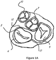
- Figure 1A shows a short axis section of the four valves in a heart.
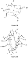
- FIG 1B there is an illustration of the mitral valve with posterior leaflet 4 sectioned into P1, P2, P3 and anterior leaflet 5 sectioned into A1, A2, and A3. These sectioning methods are common knowledge and acceptable among those skilled in the art.
- Figure 1B also shows a commissure 19 between A1 and P1 and a commissure 20 is the commissure between A3 and P3.
- Figure 2A is a three chamber view (long axis) of the heart. In this view, the left atrium 8, left ventricle 2, and right ventricle 1 are shown.
- the aortic valve 7 is at the end of the left ventricle outflow tract (LVOT) 13.
- the mitral valve apparatus with mitral leaflets includes anterior leaflet 5 and posterior leaflet 4 attached to the chordae tandea 6 and papillary muscles 3.
- This view is a section of the mitral valve through the A2 (shown as area 22 in figure 1B ) and P2 (shown as area 21 in figure 1B ) areas of the mitral leaflets.
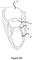
- Figure 2B is a two chamber view (long axis) of the heart. In this view the left atrium 8 and left ventricle 2 are shown.
- the mitral valve apparatus includes the posterior mitral leaflet 4 attached to the chordae tandea 6 and papillary muscles 3. This view is a section of the mitral valve through the commissures 19 and 20 of the mitral leaflets.
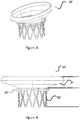
- FIG 3 is a perspective view of a stent 30 configured for placement in a native mitral or tricuspid valve.
- the stent 30 in figure 4 is a front view of the stent 30 shown in figure 3 .
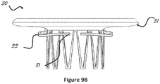
- the stent 30 includes an upper section 31 (also referred to herein as "inflow section” 31) having an enlarged diameter (circumference) or flared end that tapers into a lower section 32 (also referred to herein as "outflow section” 32) of the frame having a reduced diameter (circumference).
- the upper section 31 and/or the lower section 32 may have different shape than circular.
- the stent 30 might have any combination of shapes and figures 5A-5H are only examples of the different shapes possible and other may apply as well.
- Migration blocker rods 33 shown in figures 3 and 4 are separated rods, which after deployment lean against the native annulus and prevent migration of the stent into the atrium 8 shown in figure 2A .
- the migration blocker rods 33 can be in different lengths with different ends and additional features can be added on them, such as: A. leading mechanism to ensure connectivity, after deployment, between different migration blocker rods; B. locking mechanism between the rods; C. barbs to prevent rocking; and D. features that lock the migration blocker rods against the upper section 31 of the frame 30.
- the migration blocker rods of the invention all comprise the B. locking mechanism between the rods.
- the valve can be either bi-leaflet or tri-leaflet as long as it performs as required and can be made out of any tissue, polymer, or other material, as long as it is biocompatible.
- the stent 30 can be self-expanding stent made of a shape memory material such as, for example, Nitinol. It can be cut of tube, sheet, or/and a pattern that allows crimping and expanding like braided wires or different technique that attaches wires as long as it performs well.
- the stent 30 can be a combination of a self-expanding stent and a balloon expandable stent.
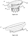
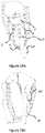
- figures 13A-13D demonstrate an upper section 31 including a shape memory alloy that functions as a self-expandable frame, and a lower section 32 including a balloon expandable stent that requires balloon inflation for final deployment.
- the two sections can be attached in any way. For example, welding, mechanical attachment (as shown in figures 13A-13D ), and/or additional features that attach them are only some of the ways to attach the two sections of the stent assembly.
- the raw material of the stent 30 can be metal or any kind that is biocompatible.
- the stent 30 may include a combination of two or more different materials. For example, one part from stainless steel 316/316L and another part from Nitinol. Other materials such as cobalt chrome are only examples, and other materials can be used as well.
- the design of the frame 30, either if it is from one part or more, is configured to allow crimping the prosthesis into a low profile shaft (equal or under 13 mm outer diameter (OD)). Patterns that allow this are known and crisscross patterns as shown for example in figures 3 and 4 for the outflow section 32 or braided stents are two examples and other may be applied as well.
- the migration blocker rods 33 of the stent 30 lean against the native annulus of the tricuspid or mitral valve, in general. When used in the mitral position, the migration blocker rods 33 may lean, in specific, against the mitral groove 14 shown in figure 2A in the posterior side and against the left fibrous trigon 18 and the right fibrous trigon 17 in the anterior side shown in figure 1A .
- the flared upper section 31 prevents any migration of the stent 30 into the ventricle 1 or 2 shown in figure 2A and helps provide sealing between the stent and the native apparatus by verifying good intimate contact and correlation between the inflow section geometry and the native shape of the mitral annulus and left atrium.
- an elliptical shape allows reducing the inflow section projection and therefore reduces the area that faces high pressure during systole. This feature reduces the axial forces that the prosthesis faces and needs to be anchored against.
- an elliptical shape assures continuous contact between the upper section 31 and the atrium and prevents any para valvular leakage (PVL). Any other shape that will at the same time prevent PVL and minimize the projection of the inflow is desired.
- the curvature that defines the transition zone and/or the inflow section profile may be configured to increase or decrease the clamping effect between migration blocker rods 33 and the inflow section 31.
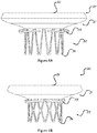
- Figures 9A and 9B show two examples and any other curvature that allows the upper section to be fixated in the atrium and the migration blocker rods to stay under the native annulus in the ventricle is acceptable.
- migration blocker rods 33 which prevent from the valve from migrating into the left atrium.
- the migration blocker rods 33 go in between the chordae under the native commissures 19 and 20 shown in figure 1B and leans against the mitral annulus from behind the native leaflets.
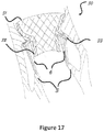
- Figures 14A, 14B , 15, 16A , 16B , and 17 show the extraction of the migration blocker rods from the stent, passing through the chordae and turning around the native leaflets. At the final position, the rods 33 lean against the native annulus.
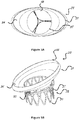
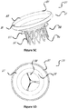
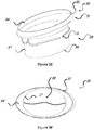
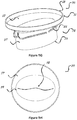
- Figures 5A-5H represents different combinations of the inflow and outflow profiles.
- the inflow profile in the illustrated embodiments can be either circular 57 (as shown in figures 5C, 5D , 5G, and 5H ) or elliptical 54 (as shown in figure 5A, 5B , 5E, and 5F ), or any other shape that fits the native anatomy of the atrium.
- the outflow profile can be either circular 58 (as shown in figures 5A, 5B , 5C and 5D ) or elliptical 59 (as shown in figures 5E, 5F , 5G and 5H ), or any other shape that fits to withhold a prosthetic valve inside, either bi leaflet or tri leaflet.
- Figures 5A-5H illustrate, by way of example, only four combinations out of many possible of the options for the design of the stent 30.
- the circumference of the inflow section 31 and its upper end 55 can vary between about 225 mm to 90 mm. This large variation is due to the target population of the device, which some have a very large atrium.
- the circumference of the outflow section 32 and its lower end 56 can vary between about 110 mm to 60 mm. This variation is to allow different sizes of valves inside the outflow according to the acceptable standards, if they exist, for the mitral and tricuspid position.
- the height of the stent may vary between about 20 mm to 60 mm, as long as it doesn't injure the left ventricle walls by the lower section 32 and lower end 56 and doesn't interfere with the flow from the pulmonary veins and/or cause any risk relatively to the left appendage.
- the valve 52 (shown in figures 5A , 5C , 5F , and 5H ) can be either bi-leaflet or tri-leaflet as long as it performs as required and can be made out of any tissue, polymer, or other material as long as it is biocompatible.
- the stent 30 can be a self-expanding stent made of a shape memory material such as, for example, Nitinol. It can be cut of tube, sheet, or/and a pattern that allows crimping and expanding like braided wires or a different technique that attaches wires as long as it performs well.
- an illustrated tri leaflet valve 52 is mounted in the circular outflow section 32.
- the valve 52 is configured such that the flow of blood goes substantially only in one direction and that substantially no back flow will occur through the valve according to the acceptable standards.
- the valve 52 can be composed from biological tissue such as pericardium or alternatively from a polymer, fabric, etc.
- valve 52 in the outflow section 32 can be bi leaflet.
- FIGS 6A and 6B there is a front view of the stent 30 according to certain embodiments. It is illustrated as an example that the stent 30 can have any number of rows of struts (illustrated as "V" shaped structural supports), as long as the struts allow crimping into a catheter and deployment to the final configuration.
- the outflow section 32 can have either 1 (one) row of struts or more. In the illustrated embodiments, there is an example of an outflow section 32 with 1 (one) row of struts in figure 6A , and an embodiment of an outflow section 32 with 2 (two) rows of struts in figure 6B . This is not limiting and more rows can be added.
- the inflow section 31 also includes expandable struts.
- the inflow section 31 may be designed in a similar manner as that of the outflow section 32 with a criss-cross pattern and/or any number of rows of struts, as long as the expandable struts allow crimping and expanding of the inflow section 31 to its different configurations.
- Figures 7A, 7B , and 7C illustrate the migration blocker rods 33 from three different views.
- Figure 7A illustrates the migration blocker rods 33 in stent 30 from a front view
- figure 7B illustrates the migration blocker rods 33 in stent 30 from a side view
- figure 7C illustrates the migration blocker rods 33 in stent 30 from a bottom view.
- the rods 33 are configured to be attached to the stent 30 either to the inflow section 31 or to the outflow section 32 at the area where these sections are attached to each other, and to provide axial fixation of the stent 30 at the target site.
- the migration blocker rods 33 around the posterior leaflet 4 are configured to lean against the mitral groove 14 and prevent any migration and axial movement in the posterior side.
- the migration blocker rods 33 around the anterior leaflet 5 are configured to lean against the left and right fibrous trigons 17 and 18 and prevent any migration and axial movement in the anterior side.
- migration blocker rods 33 there are one, two, or more migration blocker rods 33 around the posterior leaflet 4. There are another one, two, or more migration blocker rods 33 around the anterior leaflet 5.
- the quantity of the migration blockers can vary from two to multiple rods and in the certain illustrated embodiments there are four of them only for visualization and as example. In other embodiments, the quantity of migration blocker rods 33 can be any number from two to eighteen.
- the migration blocker rods 33 may include a leading mechanism behind the leaflet to ensure the attachment of the rods to one another and include a locking mechanism that prevents them from separating after deployment.
- the migration blocker rods 33 can be in different lengths with different ends 81 and additional features can be added on them.
- the end 81 of the migration blocker rods 33 can be seen in figures 8A and 8B . It can be seen that the distance between them can vary from zero, at minimum (they can touch each other), to, at maximum, half the circumference of the outflow section. In the later, the length of the rods 33 is very short and the point of leaning against the annulus is under the commissures 19 and 20 in figure 1B .
- FIGS 10A and 10B there is a leading mechanism 100 at the end 81 of the migration blocker rods 33 that allows connecting two migration blocker rods 33 that come from opposite commissures 19 and 20.
- the leading mechanism 100 allows two different migration blocker rods 33 to meet and attach to each other. Due to the nature of beating heart procedures and no direct visualization (only through X-ray and ultrasound), it may be useful to have such a mechanism 100 that allows leading one rod 33 into the other to assure that the two can be connected.
- the illustrated mechanism 100 is only one example but others can be designed and might include wire, suture, metallic, and/or plastic members, etc.
- FIGS 11A, 11B , and 11C there is a snapping mechanism 110 at the end 81 of the migration blocker rods 33 that allows connecting two migration blocker rods 33 that come from opposite commissures 19 and 20 and lock them one into the other. Once two migration blocker rods 33 are attached and locked the stent is firmly secured in place and the rods 33 can't be crimped back to the crimped configuration unless the snap mechanism 110 is released.
- the snap illustrated in figures 11A, 11B , and 11C is one example for such mechanism and others with additional members as metallic and/or plastic parts, wire, suture can be added.
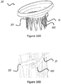
- Figures 12A and 12B illustrate migration blocker rods 33 that include barbs 120 configured to penetrate the mitral annulus from the ventricle side and ensure no relative movement between the frame 30 and the mitral annulus.
- the barbs 120 that penetrated the mitral annulus can be locked into the inflow section of the frame from the atrium side or locked into an additional ring.
- Figure 12B is a zoom on the isometric view of a barb that is part of a migration blocker rod 33 that penetrated through the annulus into the inflow section 31.
- the migration blocker rods 33 can be cut from the same tube and heat treated to the final shape.
- the migration blocker rods 33 can be cut from different tube and be attached to the main frame differently using a direct attachment such as welding or with additional members such as sutures, metallic parts, etc.
- the migration blocker rods 33 can be crimped distally to the main frame, proximally to the main frame and on top of it.
- the migration blocker rods 33 might be covered with a fabric, soft tissue, and/or polymer to prevent any damage to the annulus apparatus.
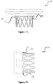
- Figures 13A, 13B , 13C and 13D illustrate a stent 30 that includes two different sections.
- the inflow section 31 is a self-expanding stent made from a shape memory alloy and functions as a self-expandable frame
- the lower section 32 is a balloon expandable stent that requires balloon inflation for final deployment.
- Figure 13A is an isometric view of the two sections attached together through an attachment member 130.
- the attachment member 130 can be part of the inflow section 31, outflow section 32, both the inflow section 31 and the outflow section 32, or/and as an additional member.
- inflow section 31 made out of shape memory alloy where the migration blocker rods 33 are part of it.
- inflow section 31 and the migration blocker rods 33 may be formed from the same piece of shape memory material.
- the migration blocker rods 33 can be omitted, or designed differently.
- an attachment feature for connecting to the outflow section 32 can be added.
- An example of such a feature is a metallic flange that is cut of the frame and illustrated in the attached embodiments as attachment member 130.
- Figure 13C illustrates an example of an outflow section 32 made out of an alloy such as stainless steel (StSt), such as StSt 316/ StSt 316L.
- the outflow section 32 can be made out of self-expandable alloy such as shape memory alloy and might include the migration blocker rods 33.
- an attachment feature for connecting to the inflow section 31 can be added.
- An example of such a feature is a metallic flange that is cut of the frame and illustrated in the attached embodiments as attachment member 130.
- Figure 13D illustrates an enlarged view of the attachment feature 130 between the inflow section 31 and the outflow section 32.
- the attachment feature 130 includes two metallic flanges. One is part of the inflow section 31 and one is part of the outflow section 32. The two flanges can be attached together by snapping one to another, suturing them together, or any other attachment method.
- Figure 14A and 14B illustrate how the stent 30 may be positioned in the mitral valve.
- the section of the heart illustrates a two chamber view and the cross-section of the drawing passes through the mitral valve commissures. It can be seen that the stent 30 is behind the posterior leaflet 4, the migration blocker rods 33 pop out from the commissures 19 and 20, and the end 81 of the migration blocker rods 33 is in the P2 section of the leaflet (area 21 in figure 1B ).
- the section of the heart illustrates a three chamber view and the cross-section of the drawing passes through the A2 and P2 (areas 21 and 22 in figure 1B ) of the native valve.
- the stent 30 is between the posterior leaflet 4 and anterior leaflet 5
- the migration blocker rods 33 pop out from the commissures area
- the end 81 of the migration blocker rods 33 is located in the posterior side under the mitral groove 14 and under the left and right fibrous trigons (18 and 17 in figure 1A ) in the anterior side.
- Figure 15 illustrates the stent 30 in the mitral valve from a short axis view from the atrial side.
- the migration blocker rods 33 are located in the ventricle side under the mitral leaflets.
- Figures 16A and 16B illustrate an additional feature that can be added to the migration blocker rods 33.
- the barbs 120 are part of the migration blocker rods 33 and designed in a way that after deployment they penetrate the mitral annulus and/or mitral leaflets and anchor the stent to the annulus.
- the barbs 120 can be integral part of the migration blocker rods 33 or additional member that is assembled on the barbs.
- the barbs 120 may be configured so that they have an opposite member or feature in the inflow section 31 in a way that after crossing the tissue they lock into the inflow section.
- Figure 17 is an additional illustration that shows how the migration blocker rods 33 pass between the chordae tandea 6 in the commissures 19 and 20.
- Figure 18 is an additional drawing illustrating how the migration blocker rod 33 leans against the mitral groove 14 in the posterior side and the left and right fibrous trigons on the anterior side.
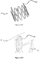
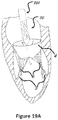
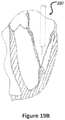
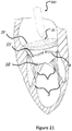
- Figures 19A , 19B , 20 , and 21 show an example of a trans atrial approach for trans catheter implantation in the mitral position.
- the catheter is advanced through the left atrium 8 and then through the native mitral valve to the left ventricle.
- the stent 30 in this figure is crimped into the catheter shaft 220.
- the migration blocker rods are as well crimped in the shaft 220 and can be crimped distally toward the apex 16, proximally toward the entering point to the left atrium, or on top of the main frame 30.
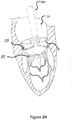
- Figure 20 shows the deployment of the stent 30.
- the migration blocker rods 33 pass through the chordae 6 under the native commissures and circle the native leaflets.
- the migration blocker rods 33 are configured, in certain embodiments, to bypass or encircle the native leaflets without clamping them to the main frame 30. Then, a completion of the deployment results in clamping the native annulus and allowing the rods 33 to prevent migration and rocking.
- Figure 21 shows that the catheter 220 is withdrawn backwards after completion of the deployment.
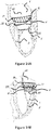
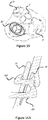
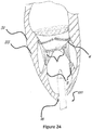
- Figures 22A, 22B , 23 , and 24 show an example of a trans apical approach for trans catheter implantation in the mitral position.
- the catheter shaft 220 is advanced through the apex 16 of the heart and then through the native mitral valve to the left atrium.
- the stent 30 in this figure is crimped into the catheter shaft 220.
- the migration blocker rods are as well crimped in the shaft and can be crimped distally toward the atrium, proximally toward the entering point to the apex 16, or on top of the main frame 30.
- Figure 23 shows the deployment of the stent 30.
- the migration blocker rods 33 pass through the chordae 6 under the native commissures and circle the native leaflets. Then, a completion of the deployment results in clamping the native annulus and allowing the rods 33 to prevent migration and rocking.
- Figure 24 shows that the catheter is withdrawn backwards after completion of the deployment.
Landscapes
- Health & Medical Sciences (AREA)
- Cardiology (AREA)
- Engineering & Computer Science (AREA)
- Biomedical Technology (AREA)
- Heart & Thoracic Surgery (AREA)
- Transplantation (AREA)
- Oral & Maxillofacial Surgery (AREA)
- Vascular Medicine (AREA)
- Life Sciences & Earth Sciences (AREA)
- Animal Behavior & Ethology (AREA)
- General Health & Medical Sciences (AREA)
- Public Health (AREA)
- Veterinary Medicine (AREA)
- Mechanical Engineering (AREA)
- Prostheses (AREA)
Claims (14)
- Prothetische Mitralklappenanordnung, umfassend:
einen radial ausdehnbaren Stent (30) einschließend:einen oberen Abschnitt (31), der anatomisch angepasst ist, um zu einem Mitralklappenanulus innerhalb eines linken Atriums (8) eines Herzens zu passen;einen unteren Abschnitt (32), der mit dem oberen Abschnitt (31) gekoppelt und so angepasst ist, dass er in den Mitralklappenanulus passt; undMigrationsblockierstangen (33), die sich um mindestens einen Teil eines Umfangs des unteren Abschnitts erstrecken, wobei die Migrationsblockierstangen (33) eine axiale Bewegung des Stents (30) in Bezug auf den Mitralklappenanulus verhindern; undeine Ersatzklappe, die mit dem Stent (30) gekoppelt ist;wobei die prothetische Mitralklappenanordnung dadurch gekennzeichnet ist, dass die Migrationsblockierstangen (33) zwei oder mehr Migrationsblockierstäbe (33) umfassen, die so angepasst sind, dass sie während der Implantation miteinander verrasten. - Prothetische Mitralklappenanordnung nach Anspruch 1, wobei der radial ausdehnbare Stent (30) dafür angepasst ist, dass er sich ausdehnt, um den Mitralklappenring einzuklemmen, indem er sich von beiden Seiten des Mitralklappenanulus ausdehnt, und wobei sich die Migrationsblockierstangen (33) hinter nativen Blättchen in einem linken Ventrikel befinden, und sich der obere Abschnitt über dem Mitralklappenanulus in einem linken Vorhof befindet.
- Prothetische Mitralklappenanordnung nach Anspruch 1, wobei die Ersatzklappe eine bikuspide oder trikuspide Klappe (52) umfasst.
- Prothetische Mitralklappenanordnung nach Anspruch 1, wobei die Migrationsblockierstangen (33) zwei oder mehr Migrationsblockierstangen (33) umfassen, die dafür angepasst sind, um durch den Mitralklappenanulus in den oberen Abschnitt einzurasten (31).
- Prothetische Mitralklappenanordnung nach Anspruch 1, wobei die Migrationsblockierstangen (33) zwei oder mehr Migrationsblockierstangen (33) umfassen, die Widerhaken (120) aufweisen, um ein Schaukeln zu verhindern.
- Prothese zum Befestigen einer perkutan implantierbaren Ersatzklappe in einem Herzen, umfassend:einen radial ausdehnbaren Einlaufabschnitt (31), der in einer entfalteten Konfiguration dafür angepasst ist, um innerhalb eines Atriums eines Herzens benachbart zu einem nativen Klappenanulus einer Herzklappe implantiert zu werden, wobei der Einlaufabschnitt (31) eine proximale Öffnung und eine distale Öffnung aufweist, wobei die proximale Öffnung einen größeren Umfang als die distale Öffnung aufweist, so dass sich der Einlaufabschnitt (31) verjüngt;einen radial ausdehnbaren Abflussabschnitt (32), der mit der distalen Öffnung des Einlaufabschnitts (31) gekoppelt ist, wobei der Abflussabschnitt (32) in einer entfalteten Konfiguration dafür angepasst ist, dass er durch den nativen Klappenanulus und zumindest teilweise in einen Ventrikel des Herzens implantiert wird; undzwei oder mehr Migrationsblockierstangen (33), die sich in Umfangsrichtung um mindestens einen Abschnitt des Abflussabschnitts (32) erstrecken, wobei ein Spalt zwischen den zwei oder mehreren Migrationsblockern (33) und dem Abflussabschnitt (32) daran angepasst ist, dass er native Blättchen der Herzklappe hält;wobei in einer zusammengezogenen Konfiguration die Prothese daran angepasst ist, dass sie durch einen Katheter in das Herz implantiert werden kann; undwobei in einer ausgedehnten Konfiguration die sich verjüngende Form des Einlaufabschnitts (31) im Atrium mit den zwei oder mehr Migrationsblockern (33) im Ventrikel zusammenwirkt, um die Prothese gegen den nativen Klappenanulus zu halten; undwobei die jeweiligen Enden der zwei oder mehreren Migrationsblockierstangen (33) so angepasst sind, dass sie während des Einsatzes miteinander verrasten.
- Prothese nach Anspruch 6, wobei in der ausgedehnten Konfiguration die proximale Öffnung des Einlaufabschnittes (31), die distale Öffnung des Einlaufabschnittes (31) und ein Umfang des Abflussabschnittes (32) jeweils im Wesentlichen kreisförmig sind.
- Prothese nach Anspruch 6, wobei in der ausgedehnten Konfiguration die proximale Öffnung des Einlaufabschnittes (31) elliptisch ist, und die distale Öffnung des Einlaufabschnittes und ein Umfang des Abflussabschnitts (32) jeweils im Wesentlichen kreisförmig sind.
- Prothese nach Anspruch 6, wobei in der ausgedehnten Konfiguration die proximale Öffnung des Einlaufabschnittes (31), die distale Öffnung des Einlaufabschnittes (31) und ein Umfang des Abflussabschnittes (32) jeweils elliptisch sind.
- Prothese nach Anspruch 6, wobei in der ausgedehnten Konfiguration die proximale Öffnung des Einlaufabschnittes (31) im Wesentlichen kreisförmig ist, und die distale Öffnung des Einlaufabschnittes (31) und ein Umfang des Abflussabschnittes (32) jeweils elliptisch sind.
- Prothese nach Anspruch 6, wobei der Einlaufabschnitt (31) ein Formgedächtnismaterial umfasst, und wobei der Abflußabschnitt (32) eine oder mehrere Reihen von ausdehnbaren Verstrebungen umfasst.
- Prothese nach Anspruch 6, wobei die zwei oder mehreren Migrationsblockierstangen (33) Widerhaken aufweisen (120), die daran angepasst sind, sich in der ausgedehnten Konfiguration durch den nativen Klappenanulus zu erstrecken und in den Einlaufabschnitt (31) einzurasten.
- Prothese nach Anspruch 6, wobei der Einlaufabschnitt (31) und der Abflussabschnitt (32) voneinander trennbar sind, wobei die prothetische Klappenanordnung ferner mehrere Befestigungselemente umfasst, um den Abflussabschnitt (32) entfernbar mit dem Einlaufabschnitt (31) zu koppeln.
- Prothese nach Anspruch 6, wobei der Einlaufabschnitt (31) dafür angepasst ist, eine Ersatzklappe zu befestigen.
Priority Applications (1)
| Application Number | Priority Date | Filing Date | Title |
|---|---|---|---|
| EP19170261.2A EP3533417A1 (de) | 2013-05-22 | 2013-05-22 | Transkatheterherzklappe für mitral- oder trikuspidklappenersatz |
Applications Claiming Priority (1)
| Application Number | Priority Date | Filing Date | Title |
|---|---|---|---|
| PCT/US2013/042275 WO2014189509A1 (en) | 2013-05-22 | 2013-05-22 | Transcatheter prosthetic valve for mitral or tricuspid valve replacement |
Related Child Applications (2)
| Application Number | Title | Priority Date | Filing Date |
|---|---|---|---|
| EP19170261.2A Division-Into EP3533417A1 (de) | 2013-05-22 | 2013-05-22 | Transkatheterherzklappe für mitral- oder trikuspidklappenersatz |
| EP19170261.2A Division EP3533417A1 (de) | 2013-05-22 | 2013-05-22 | Transkatheterherzklappe für mitral- oder trikuspidklappenersatz |
Publications (3)
| Publication Number | Publication Date |
|---|---|
| EP2999433A1 EP2999433A1 (de) | 2016-03-30 |
| EP2999433A4 EP2999433A4 (de) | 2017-01-25 |
| EP2999433B1 true EP2999433B1 (de) | 2019-07-10 |
Family
ID=51933906
Family Applications (2)
| Application Number | Title | Priority Date | Filing Date |
|---|---|---|---|
| EP19170261.2A Pending EP3533417A1 (de) | 2013-05-22 | 2013-05-22 | Transkatheterherzklappe für mitral- oder trikuspidklappenersatz |
| EP13885021.9A Active EP2999433B1 (de) | 2013-05-22 | 2013-05-22 | Transkatheter-herzklappe für mitral- oder trikuspidklappenersatz |
Family Applications Before (1)
| Application Number | Title | Priority Date | Filing Date |
|---|---|---|---|
| EP19170261.2A Pending EP3533417A1 (de) | 2013-05-22 | 2013-05-22 | Transkatheterherzklappe für mitral- oder trikuspidklappenersatz |
Country Status (4)
| Country | Link |
|---|---|
| US (1) | US20160089235A1 (de) |
| EP (2) | EP3533417A1 (de) |
| IL (1) | IL242635B (de) |
| WO (1) | WO2014189509A1 (de) |
Cited By (13)
| Publication number | Priority date | Publication date | Assignee | Title |
|---|---|---|---|---|
| US10856984B2 (en) | 2017-08-25 | 2020-12-08 | Neovasc Tiara Inc. | Sequentially deployed transcatheter mitral valve prosthesis |
| US10940001B2 (en) | 2012-05-30 | 2021-03-09 | Neovasc Tiara Inc. | Methods and apparatus for loading a prosthesis onto a delivery system |
| US11311376B2 (en) | 2019-06-20 | 2022-04-26 | Neovase Tiara Inc. | Low profile prosthetic mitral valve |
| US11357622B2 (en) | 2016-01-29 | 2022-06-14 | Neovase Tiara Inc. | Prosthetic valve for avoiding obstruction of outflow |
| US11389291B2 (en) | 2013-04-04 | 2022-07-19 | Neovase Tiara Inc. | Methods and apparatus for delivering a prosthetic valve to a beating heart |
| US11413139B2 (en) | 2011-11-23 | 2022-08-16 | Neovasc Tiara Inc. | Sequentially deployed transcatheter mitral valve prosthesis |
| US11419720B2 (en) | 2010-05-05 | 2022-08-23 | Neovasc Tiara Inc. | Transcatheter mitral valve prosthesis |
| US11464631B2 (en) | 2016-11-21 | 2022-10-11 | Neovasc Tiara Inc. | Methods and systems for rapid retraction of a transcatheter heart valve delivery system |
| US11491006B2 (en) | 2019-04-10 | 2022-11-08 | Neovasc Tiara Inc. | Prosthetic valve with natural blood flow |
| US11497602B2 (en) | 2012-02-14 | 2022-11-15 | Neovasc Tiara Inc. | Methods and apparatus for engaging a valve prosthesis with tissue |
| US11602429B2 (en) | 2019-04-01 | 2023-03-14 | Neovasc Tiara Inc. | Controllably deployable prosthetic valve |
| US11737872B2 (en) | 2018-11-08 | 2023-08-29 | Neovasc Tiara Inc. | Ventricular deployment of a transcatheter mitral valve prosthesis |
| US11779742B2 (en) | 2019-05-20 | 2023-10-10 | Neovasc Tiara Inc. | Introducer with hemostasis mechanism |
Families Citing this family (40)
| Publication number | Priority date | Publication date | Assignee | Title |
|---|---|---|---|---|
| EP2600799B1 (de) | 2010-08-04 | 2017-05-17 | ValCare, Inc. | Herzklappenreparatur mithilfe eines perkutanen transkatheters |
| CA2822381C (en) | 2010-12-23 | 2019-04-02 | Foundry Newco Xii, Inc. | System for mitral valve repair and replacement |
| US9402721B2 (en) | 2011-06-01 | 2016-08-02 | Valcare, Inc. | Percutaneous transcatheter repair of heart valves via trans-apical access |
| WO2012177942A2 (en) | 2011-06-21 | 2012-12-27 | Hanson Gifford, Iii | Prosthetic heart valve devices and associated systems and methods |
| EP4252714A3 (de) | 2011-10-19 | 2023-12-20 | Twelve, Inc. | Vorrichtung für den ersatz einer herzklappe |
| US9039757B2 (en) | 2011-10-19 | 2015-05-26 | Twelve, Inc. | Prosthetic heart valve devices, prosthetic mitral valves and associated systems and methods |
| US11202704B2 (en) | 2011-10-19 | 2021-12-21 | Twelve, Inc. | Prosthetic heart valve devices, prosthetic mitral valves and associated systems and methods |
| US9655722B2 (en) | 2011-10-19 | 2017-05-23 | Twelve, Inc. | Prosthetic heart valve devices, prosthetic mitral valves and associated systems and methods |
| US10016271B2 (en) | 2011-10-19 | 2018-07-10 | Twelve, Inc. | Prosthetic heart valve devices, prosthetic mitral valves and associated systems and methods |
| US9763780B2 (en) | 2011-10-19 | 2017-09-19 | Twelve, Inc. | Devices, systems and methods for heart valve replacement |
| US9839519B2 (en) | 2012-02-29 | 2017-12-12 | Valcare, Inc. | Percutaneous annuloplasty system with anterior-posterior adjustment |
| US9180008B2 (en) | 2012-02-29 | 2015-11-10 | Valcare, Inc. | Methods, devices, and systems for percutaneously anchoring annuloplasty rings |
| US9579198B2 (en) | 2012-03-01 | 2017-02-28 | Twelve, Inc. | Hydraulic delivery systems for prosthetic heart valve devices and associated methods |
| US10166100B2 (en) | 2013-03-15 | 2019-01-01 | Valcare, Inc. | Systems and methods for delivery of annuloplasty rings |
| WO2014189974A1 (en) | 2013-05-20 | 2014-11-27 | Twelve, Inc. | Implantable heart valve devices, mitral valve repair devices and associated systems and methods |
| US10813751B2 (en) | 2013-05-22 | 2020-10-27 | Valcare, Inc. | Transcatheter prosthetic valve for mitral or tricuspid valve replacement |
| EP3003187B1 (de) | 2013-05-24 | 2023-11-08 | Valcare, Inc. | Herz- und periphervaskulärklappenersatz in verbindung mit einem stützring |
| US11058417B2 (en) | 2013-06-28 | 2021-07-13 | Valcare, Inc. | Device, system, and method to secure an article to a tissue |
| PL3102152T3 (pl) | 2014-02-04 | 2020-02-28 | Innovheart S.R.L. | Urządzenie protetyczne dla zastawki serca |
| US20160095701A1 (en) * | 2014-10-07 | 2016-04-07 | St. Jude Medical, Cardiology Division, Inc. | Bi-Leaflet Mitral Valve Design |
| WO2017035002A1 (en) | 2015-08-21 | 2017-03-02 | Twelve Inc. | Implantable heart valve devices, mitral valve repair devices and associated systems and methods |
| EP3448316B1 (de) | 2016-04-29 | 2023-03-29 | Medtronic Vascular Inc. | Herzklappenprothesenvorrichtungen mit angebundenen ankern |
| CN107753153B (zh) | 2016-08-15 | 2022-05-31 | 沃卡尔有限公司 | 用于治疗心脏瓣膜关闭不全的装置和方法 |
| US11241307B2 (en) | 2016-10-13 | 2022-02-08 | Boston Scientific Scimed, Inc. | Replacement heart valve with diaphragm |
| US10653523B2 (en) | 2017-01-19 | 2020-05-19 | 4C Medical Technologies, Inc. | Systems, methods and devices for delivery systems, methods and devices for implanting prosthetic heart valves |
| US10561495B2 (en) | 2017-01-24 | 2020-02-18 | 4C Medical Technologies, Inc. | Systems, methods and devices for two-step delivery and implantation of prosthetic heart valve |
| CN108618871A (zh) | 2017-03-17 | 2018-10-09 | 沃卡尔有限公司 | 具有多方向锚部的二尖瓣或三尖瓣修复系统 |
| US10575950B2 (en) | 2017-04-18 | 2020-03-03 | Twelve, Inc. | Hydraulic systems for delivering prosthetic heart valve devices and associated methods |
| US10433961B2 (en) | 2017-04-18 | 2019-10-08 | Twelve, Inc. | Delivery systems with tethers for prosthetic heart valve devices and associated methods |
| US10702378B2 (en) | 2017-04-18 | 2020-07-07 | Twelve, Inc. | Prosthetic heart valve device and associated systems and methods |
| US10792151B2 (en) | 2017-05-11 | 2020-10-06 | Twelve, Inc. | Delivery systems for delivering prosthetic heart valve devices and associated methods |
| US10646338B2 (en) | 2017-06-02 | 2020-05-12 | Twelve, Inc. | Delivery systems with telescoping capsules for deploying prosthetic heart valve devices and associated methods |
| US10709591B2 (en) | 2017-06-06 | 2020-07-14 | Twelve, Inc. | Crimping device and method for loading stents and prosthetic heart valves |
| US10786352B2 (en) | 2017-07-06 | 2020-09-29 | Twelve, Inc. | Prosthetic heart valve devices and associated systems and methods |
| US10729541B2 (en) | 2017-07-06 | 2020-08-04 | Twelve, Inc. | Prosthetic heart valve devices and associated systems and methods |
| US11666444B2 (en) | 2017-08-03 | 2023-06-06 | The Regents Of The University Of California | Atrial cage for placement, securing and anchoring of atrioventricular valves |
| US11857441B2 (en) | 2018-09-04 | 2024-01-02 | 4C Medical Technologies, Inc. | Stent loading device |
| WO2020117842A1 (en) | 2018-12-03 | 2020-06-11 | Valcare, Inc. | Stabilizing and adjusting tool for controlling a minimally invasive mitral / tricuspid valve repair system |
| WO2021011702A1 (en) | 2019-07-15 | 2021-01-21 | Valcare, Inc. | Transcatheter bio-prosthesis member and support structure |
| US11931253B2 (en) | 2020-01-31 | 2024-03-19 | 4C Medical Technologies, Inc. | Prosthetic heart valve delivery system: ball-slide attachment |
Family Cites Families (12)
| Publication number | Priority date | Publication date | Assignee | Title |
|---|---|---|---|---|
| US6425916B1 (en) * | 1999-02-10 | 2002-07-30 | Michi E. Garrison | Methods and devices for implanting cardiac valves |
| US20060195183A1 (en) * | 2005-02-18 | 2006-08-31 | The Cleveland Clinic Foundation | Apparatus and methods for replacing a cardiac valve |
| US8449599B2 (en) * | 2009-12-04 | 2013-05-28 | Edwards Lifesciences Corporation | Prosthetic valve for replacing mitral valve |
| US20110224785A1 (en) * | 2010-03-10 | 2011-09-15 | Hacohen Gil | Prosthetic mitral valve with tissue anchors |
| CA2822381C (en) * | 2010-12-23 | 2019-04-02 | Foundry Newco Xii, Inc. | System for mitral valve repair and replacement |
| CN103476362A (zh) * | 2011-01-11 | 2013-12-25 | 汉斯·赖纳·菲古拉 | 用于替换心脏动脉心室瓣膜的瓣膜假体 |
| US9078747B2 (en) | 2011-12-21 | 2015-07-14 | Edwards Lifesciences Corporation | Anchoring device for replacing or repairing a heart valve |
| AU2013264730B2 (en) | 2012-05-20 | 2018-02-01 | Tel Hashomer Medical Research Infrastructure And Services Ltd. | Prosthetic mitral valve |
| US9468525B2 (en) * | 2012-08-13 | 2016-10-18 | Medtronic, Inc. | Heart valve prosthesis |
| US20140114407A1 (en) * | 2012-10-22 | 2014-04-24 | ConcieValve LLC | Methods for inhibiting stenosis, obstruction, or calcification of a stented heart valve |
| CN103345118A (zh) * | 2013-07-05 | 2013-10-09 | 深圳市华星光电技术有限公司 | 光罩、玻璃基板及其制造方法 |
| US9393166B2 (en) * | 2013-12-19 | 2016-07-19 | King Fahd University Of Petroleum And Minerals | Wheelchair suspension system comprising of an encased set of springs with a damper, and method for enhancing stability |
-
2013
- 2013-05-22 US US14/891,189 patent/US20160089235A1/en not_active Abandoned
- 2013-05-22 WO PCT/US2013/042275 patent/WO2014189509A1/en active Application Filing
- 2013-05-22 EP EP19170261.2A patent/EP3533417A1/de active Pending
- 2013-05-22 EP EP13885021.9A patent/EP2999433B1/de active Active
-
2015
- 2015-11-16 IL IL242635A patent/IL242635B/en unknown
Non-Patent Citations (1)
| Title |
|---|
| None * |
Cited By (17)
| Publication number | Priority date | Publication date | Assignee | Title |
|---|---|---|---|---|
| US11419720B2 (en) | 2010-05-05 | 2022-08-23 | Neovasc Tiara Inc. | Transcatheter mitral valve prosthesis |
| US11413139B2 (en) | 2011-11-23 | 2022-08-16 | Neovasc Tiara Inc. | Sequentially deployed transcatheter mitral valve prosthesis |
| US11497602B2 (en) | 2012-02-14 | 2022-11-15 | Neovasc Tiara Inc. | Methods and apparatus for engaging a valve prosthesis with tissue |
| US10940001B2 (en) | 2012-05-30 | 2021-03-09 | Neovasc Tiara Inc. | Methods and apparatus for loading a prosthesis onto a delivery system |
| US11617650B2 (en) | 2012-05-30 | 2023-04-04 | Neovasc Tiara Inc. | Methods and apparatus for loading a prosthesis onto a delivery system |
| US11389294B2 (en) | 2012-05-30 | 2022-07-19 | Neovasc Tiara Inc. | Methods and apparatus for loading a prosthesis onto a delivery system |
| US11389291B2 (en) | 2013-04-04 | 2022-07-19 | Neovase Tiara Inc. | Methods and apparatus for delivering a prosthetic valve to a beating heart |
| US11357622B2 (en) | 2016-01-29 | 2022-06-14 | Neovase Tiara Inc. | Prosthetic valve for avoiding obstruction of outflow |
| US11464631B2 (en) | 2016-11-21 | 2022-10-11 | Neovasc Tiara Inc. | Methods and systems for rapid retraction of a transcatheter heart valve delivery system |
| US10856984B2 (en) | 2017-08-25 | 2020-12-08 | Neovasc Tiara Inc. | Sequentially deployed transcatheter mitral valve prosthesis |
| US11793640B2 (en) | 2017-08-25 | 2023-10-24 | Neovasc Tiara Inc. | Sequentially deployed transcatheter mitral valve prosthesis |
| US11737872B2 (en) | 2018-11-08 | 2023-08-29 | Neovasc Tiara Inc. | Ventricular deployment of a transcatheter mitral valve prosthesis |
| US11602429B2 (en) | 2019-04-01 | 2023-03-14 | Neovasc Tiara Inc. | Controllably deployable prosthetic valve |
| US11491006B2 (en) | 2019-04-10 | 2022-11-08 | Neovasc Tiara Inc. | Prosthetic valve with natural blood flow |
| US11779742B2 (en) | 2019-05-20 | 2023-10-10 | Neovasc Tiara Inc. | Introducer with hemostasis mechanism |
| US11311376B2 (en) | 2019-06-20 | 2022-04-26 | Neovase Tiara Inc. | Low profile prosthetic mitral valve |
| US11931254B2 (en) | 2019-06-20 | 2024-03-19 | Neovasc Tiara Inc. | Low profile prosthetic mitral valve |
Also Published As
| Publication number | Publication date |
|---|---|
| IL242635B (en) | 2022-05-01 |
| EP2999433A4 (de) | 2017-01-25 |
| WO2014189509A1 (en) | 2014-11-27 |
| EP3533417A1 (de) | 2019-09-04 |
| EP2999433A1 (de) | 2016-03-30 |
| US20160089235A1 (en) | 2016-03-31 |
Similar Documents
| Publication | Publication Date | Title |
|---|---|---|
| US11617647B2 (en) | Transcatheter prosthetic valve for mitral or tricuspid valve replacement | |
| EP2999433B1 (de) | Transkatheter-herzklappe für mitral- oder trikuspidklappenersatz | |
| US11759318B2 (en) | Multi-component designs for heart valve retrieval device, sealing structures and stent assembly | |
| US20210022856A1 (en) | Prosthetic heart valve with atrial sealing member | |
| US10888424B2 (en) | Prosthetic mitral valve coaptation enhancement device | |
| US9833313B2 (en) | Transcatheter valve replacement | |
| US9839517B2 (en) | Implantable device for treating mitral valve regurgitation | |
| EP2777615B1 (de) | Prothese zum atraumatischen Ergreifen von intraluminalem Gewebe | |
| US9095433B2 (en) | Truncated cone heart valve stent | |
| JP5685183B2 (ja) | ステント付き心臓弁装置 | |
| EP2211779A1 (de) | Transkatheter-herzklappe mit mikroankern | |
| EP3846741A1 (de) | Herzklappenprothese mit vorteilhaften dichtungs- und beladungseigenschaften | |
| CN115867230A (zh) | 假体半心脏瓣膜 |
Legal Events
| Date | Code | Title | Description |
|---|---|---|---|
| PUAI | Public reference made under article 153(3) epc to a published international application that has entered the european phase |
Free format text: ORIGINAL CODE: 0009012 |
|
| 17P | Request for examination filed |
Effective date: 20151214 |
|
| AK | Designated contracting states |
Kind code of ref document: A1 Designated state(s): AL AT BE BG CH CY CZ DE DK EE ES FI FR GB GR HR HU IE IS IT LI LT LU LV MC MK MT NL NO PL PT RO RS SE SI SK SM TR |
|
| AX | Request for extension of the european patent |
Extension state: BA ME |
|
| RIN1 | Information on inventor provided before grant (corrected) |
Inventor name: YELLIN, NADAV |
|
| DAX | Request for extension of the european patent (deleted) | ||
| A4 | Supplementary search report drawn up and despatched |
Effective date: 20170103 |
|
| RIC1 | Information provided on ipc code assigned before grant |
Ipc: A61F 2/24 20060101AFI20161221BHEP Ipc: A61F 2/844 20130101ALI20161221BHEP |
|
| GRAP | Despatch of communication of intention to grant a patent |
Free format text: ORIGINAL CODE: EPIDOSNIGR1 |
|
| STAA | Information on the status of an ep patent application or granted ep patent |
Free format text: STATUS: GRANT OF PATENT IS INTENDED |
|
| INTG | Intention to grant announced |
Effective date: 20180920 |
|
| GRAJ | Information related to disapproval of communication of intention to grant by the applicant or resumption of examination proceedings by the epo deleted |
Free format text: ORIGINAL CODE: EPIDOSDIGR1 |
|
| STAA | Information on the status of an ep patent application or granted ep patent |
Free format text: STATUS: REQUEST FOR EXAMINATION WAS MADE |
|
| GRAP | Despatch of communication of intention to grant a patent |
Free format text: ORIGINAL CODE: EPIDOSNIGR1 |
|
| INTC | Intention to grant announced (deleted) | ||
| STAA | Information on the status of an ep patent application or granted ep patent |
Free format text: STATUS: GRANT OF PATENT IS INTENDED |
|
| INTG | Intention to grant announced |
Effective date: 20181220 |
|
| GRAS | Grant fee paid |
Free format text: ORIGINAL CODE: EPIDOSNIGR3 |
|
| GRAA | (expected) grant |
Free format text: ORIGINAL CODE: 0009210 |
|
| STAA | Information on the status of an ep patent application or granted ep patent |
Free format text: STATUS: THE PATENT HAS BEEN GRANTED |
|
| AK | Designated contracting states |
Kind code of ref document: B1 Designated state(s): AL AT BE BG CH CY CZ DE DK EE ES FI FR GB GR HR HU IE IS IT LI LT LU LV MC MK MT NL NO PL PT RO RS SE SI SK SM TR |
|
| REG | Reference to a national code |
Ref country code: GB Ref legal event code: FG4D |
|
| REG | Reference to a national code |
Ref country code: CH Ref legal event code: EP Ref country code: AT Ref legal event code: REF Ref document number: 1152746 Country of ref document: AT Kind code of ref document: T Effective date: 20190715 |
|
| REG | Reference to a national code |
Ref country code: DE Ref legal event code: R096 Ref document number: 602013057785 Country of ref document: DE |
|
| REG | Reference to a national code |
Ref country code: IE Ref legal event code: FG4D |
|
| REG | Reference to a national code |
Ref country code: NL Ref legal event code: MP Effective date: 20190710 |
|
| REG | Reference to a national code |
Ref country code: LT Ref legal event code: MG4D |
|
| REG | Reference to a national code |
Ref country code: AT Ref legal event code: MK05 Ref document number: 1152746 Country of ref document: AT Kind code of ref document: T Effective date: 20190710 |
|
| PG25 | Lapsed in a contracting state [announced via postgrant information from national office to epo] |
Ref country code: PT Free format text: LAPSE BECAUSE OF FAILURE TO SUBMIT A TRANSLATION OF THE DESCRIPTION OR TO PAY THE FEE WITHIN THE PRESCRIBED TIME-LIMIT Effective date: 20191111 Ref country code: HR Free format text: LAPSE BECAUSE OF FAILURE TO SUBMIT A TRANSLATION OF THE DESCRIPTION OR TO PAY THE FEE WITHIN THE PRESCRIBED TIME-LIMIT Effective date: 20190710 Ref country code: LT Free format text: LAPSE BECAUSE OF FAILURE TO SUBMIT A TRANSLATION OF THE DESCRIPTION OR TO PAY THE FEE WITHIN THE PRESCRIBED TIME-LIMIT Effective date: 20190710 Ref country code: SE Free format text: LAPSE BECAUSE OF FAILURE TO SUBMIT A TRANSLATION OF THE DESCRIPTION OR TO PAY THE FEE WITHIN THE PRESCRIBED TIME-LIMIT Effective date: 20190710 Ref country code: NL Free format text: LAPSE BECAUSE OF FAILURE TO SUBMIT A TRANSLATION OF THE DESCRIPTION OR TO PAY THE FEE WITHIN THE PRESCRIBED TIME-LIMIT Effective date: 20190710 Ref country code: BG Free format text: LAPSE BECAUSE OF FAILURE TO SUBMIT A TRANSLATION OF THE DESCRIPTION OR TO PAY THE FEE WITHIN THE PRESCRIBED TIME-LIMIT Effective date: 20191010 Ref country code: FI Free format text: LAPSE BECAUSE OF FAILURE TO SUBMIT A TRANSLATION OF THE DESCRIPTION OR TO PAY THE FEE WITHIN THE PRESCRIBED TIME-LIMIT Effective date: 20190710 Ref country code: AT Free format text: LAPSE BECAUSE OF FAILURE TO SUBMIT A TRANSLATION OF THE DESCRIPTION OR TO PAY THE FEE WITHIN THE PRESCRIBED TIME-LIMIT Effective date: 20190710 Ref country code: NO Free format text: LAPSE BECAUSE OF FAILURE TO SUBMIT A TRANSLATION OF THE DESCRIPTION OR TO PAY THE FEE WITHIN THE PRESCRIBED TIME-LIMIT Effective date: 20191010 |
|
| PG25 | Lapsed in a contracting state [announced via postgrant information from national office to epo] |
Ref country code: RS Free format text: LAPSE BECAUSE OF FAILURE TO SUBMIT A TRANSLATION OF THE DESCRIPTION OR TO PAY THE FEE WITHIN THE PRESCRIBED TIME-LIMIT Effective date: 20190710 Ref country code: IS Free format text: LAPSE BECAUSE OF FAILURE TO SUBMIT A TRANSLATION OF THE DESCRIPTION OR TO PAY THE FEE WITHIN THE PRESCRIBED TIME-LIMIT Effective date: 20191110 Ref country code: LV Free format text: LAPSE BECAUSE OF FAILURE TO SUBMIT A TRANSLATION OF THE DESCRIPTION OR TO PAY THE FEE WITHIN THE PRESCRIBED TIME-LIMIT Effective date: 20190710 Ref country code: ES Free format text: LAPSE BECAUSE OF FAILURE TO SUBMIT A TRANSLATION OF THE DESCRIPTION OR TO PAY THE FEE WITHIN THE PRESCRIBED TIME-LIMIT Effective date: 20190710 Ref country code: AL Free format text: LAPSE BECAUSE OF FAILURE TO SUBMIT A TRANSLATION OF THE DESCRIPTION OR TO PAY THE FEE WITHIN THE PRESCRIBED TIME-LIMIT Effective date: 20190710 Ref country code: GR Free format text: LAPSE BECAUSE OF FAILURE TO SUBMIT A TRANSLATION OF THE DESCRIPTION OR TO PAY THE FEE WITHIN THE PRESCRIBED TIME-LIMIT Effective date: 20191011 |
|
| PG25 | Lapsed in a contracting state [announced via postgrant information from national office to epo] |
Ref country code: TR Free format text: LAPSE BECAUSE OF FAILURE TO SUBMIT A TRANSLATION OF THE DESCRIPTION OR TO PAY THE FEE WITHIN THE PRESCRIBED TIME-LIMIT Effective date: 20190710 |
|
| PG25 | Lapsed in a contracting state [announced via postgrant information from national office to epo] |
Ref country code: DK Free format text: LAPSE BECAUSE OF FAILURE TO SUBMIT A TRANSLATION OF THE DESCRIPTION OR TO PAY THE FEE WITHIN THE PRESCRIBED TIME-LIMIT Effective date: 20190710 Ref country code: EE Free format text: LAPSE BECAUSE OF FAILURE TO SUBMIT A TRANSLATION OF THE DESCRIPTION OR TO PAY THE FEE WITHIN THE PRESCRIBED TIME-LIMIT Effective date: 20190710 Ref country code: RO Free format text: LAPSE BECAUSE OF FAILURE TO SUBMIT A TRANSLATION OF THE DESCRIPTION OR TO PAY THE FEE WITHIN THE PRESCRIBED TIME-LIMIT Effective date: 20190710 Ref country code: PL Free format text: LAPSE BECAUSE OF FAILURE TO SUBMIT A TRANSLATION OF THE DESCRIPTION OR TO PAY THE FEE WITHIN THE PRESCRIBED TIME-LIMIT Effective date: 20190710 |
|
| PG25 | Lapsed in a contracting state [announced via postgrant information from national office to epo] |
Ref country code: IS Free format text: LAPSE BECAUSE OF FAILURE TO SUBMIT A TRANSLATION OF THE DESCRIPTION OR TO PAY THE FEE WITHIN THE PRESCRIBED TIME-LIMIT Effective date: 20200224 Ref country code: SM Free format text: LAPSE BECAUSE OF FAILURE TO SUBMIT A TRANSLATION OF THE DESCRIPTION OR TO PAY THE FEE WITHIN THE PRESCRIBED TIME-LIMIT Effective date: 20190710 Ref country code: SK Free format text: LAPSE BECAUSE OF FAILURE TO SUBMIT A TRANSLATION OF THE DESCRIPTION OR TO PAY THE FEE WITHIN THE PRESCRIBED TIME-LIMIT Effective date: 20190710 Ref country code: CZ Free format text: LAPSE BECAUSE OF FAILURE TO SUBMIT A TRANSLATION OF THE DESCRIPTION OR TO PAY THE FEE WITHIN THE PRESCRIBED TIME-LIMIT Effective date: 20190710 |
|
| REG | Reference to a national code |
Ref country code: DE Ref legal event code: R097 Ref document number: 602013057785 Country of ref document: DE |
|
| PLBE | No opposition filed within time limit |
Free format text: ORIGINAL CODE: 0009261 |
|
| STAA | Information on the status of an ep patent application or granted ep patent |
Free format text: STATUS: NO OPPOSITION FILED WITHIN TIME LIMIT |
|
| PG2D | Information on lapse in contracting state deleted |
Ref country code: IS |
|
| 26N | No opposition filed |
Effective date: 20200603 |
|
| PG25 | Lapsed in a contracting state [announced via postgrant information from national office to epo] |
Ref country code: SI Free format text: LAPSE BECAUSE OF FAILURE TO SUBMIT A TRANSLATION OF THE DESCRIPTION OR TO PAY THE FEE WITHIN THE PRESCRIBED TIME-LIMIT Effective date: 20190710 |
|
| PG25 | Lapsed in a contracting state [announced via postgrant information from national office to epo] |
Ref country code: MC Free format text: LAPSE BECAUSE OF FAILURE TO SUBMIT A TRANSLATION OF THE DESCRIPTION OR TO PAY THE FEE WITHIN THE PRESCRIBED TIME-LIMIT Effective date: 20190710 Ref country code: LI Free format text: LAPSE BECAUSE OF NON-PAYMENT OF DUE FEES Effective date: 20200531 Ref country code: CH Free format text: LAPSE BECAUSE OF NON-PAYMENT OF DUE FEES Effective date: 20200531 |
|
| REG | Reference to a national code |
Ref country code: BE Ref legal event code: MM Effective date: 20200531 |
|
| GBPC | Gb: european patent ceased through non-payment of renewal fee |
Effective date: 20200522 |
|
| PG25 | Lapsed in a contracting state [announced via postgrant information from national office to epo] |
Ref country code: LU Free format text: LAPSE BECAUSE OF NON-PAYMENT OF DUE FEES Effective date: 20200522 |
|
| PG25 | Lapsed in a contracting state [announced via postgrant information from national office to epo] |
Ref country code: IE Free format text: LAPSE BECAUSE OF NON-PAYMENT OF DUE FEES Effective date: 20200522 Ref country code: GB Free format text: LAPSE BECAUSE OF NON-PAYMENT OF DUE FEES Effective date: 20200522 |
|
| PG25 | Lapsed in a contracting state [announced via postgrant information from national office to epo] |
Ref country code: BE Free format text: LAPSE BECAUSE OF NON-PAYMENT OF DUE FEES Effective date: 20200531 |
|
| PG25 | Lapsed in a contracting state [announced via postgrant information from national office to epo] |
Ref country code: MT Free format text: LAPSE BECAUSE OF FAILURE TO SUBMIT A TRANSLATION OF THE DESCRIPTION OR TO PAY THE FEE WITHIN THE PRESCRIBED TIME-LIMIT Effective date: 20190710 Ref country code: CY Free format text: LAPSE BECAUSE OF FAILURE TO SUBMIT A TRANSLATION OF THE DESCRIPTION OR TO PAY THE FEE WITHIN THE PRESCRIBED TIME-LIMIT Effective date: 20190710 |
|
| PG25 | Lapsed in a contracting state [announced via postgrant information from national office to epo] |
Ref country code: MK Free format text: LAPSE BECAUSE OF FAILURE TO SUBMIT A TRANSLATION OF THE DESCRIPTION OR TO PAY THE FEE WITHIN THE PRESCRIBED TIME-LIMIT Effective date: 20190710 |
|
| PGFP | Annual fee paid to national office [announced via postgrant information from national office to epo] |
Ref country code: IT Payment date: 20230524 Year of fee payment: 11 Ref country code: FR Payment date: 20230524 Year of fee payment: 11 Ref country code: DE Payment date: 20230524 Year of fee payment: 11 |