EP2999202A1 - A device and the related method for estimating the stability of a digital subscriber line - Google Patents
A device and the related method for estimating the stability of a digital subscriber line Download PDFInfo
- Publication number
- EP2999202A1 EP2999202A1 EP14290283.2A EP14290283A EP2999202A1 EP 2999202 A1 EP2999202 A1 EP 2999202A1 EP 14290283 A EP14290283 A EP 14290283A EP 2999202 A1 EP2999202 A1 EP 2999202A1
- Authority
- EP
- European Patent Office
- Prior art keywords
- issues
- usage rate
- weighted
- time window
- digital subscriber
- Prior art date
- Legal status (The legal status is an assumption and is not a legal conclusion. Google has not performed a legal analysis and makes no representation as to the accuracy of the status listed.)
- Granted
Links
- 238000000034 method Methods 0.000 title claims description 18
- 238000012544 monitoring process Methods 0.000 claims abstract description 13
- 238000004590 computer program Methods 0.000 claims description 3
- BZLVMXJERCGZMT-UHFFFAOYSA-N Methyl tert-butyl ether Chemical compound COC(C)(C)C BZLVMXJERCGZMT-UHFFFAOYSA-N 0.000 description 25
- 230000006870 function Effects 0.000 description 21
- 238000013024 troubleshooting Methods 0.000 description 16
- 238000004364 calculation method Methods 0.000 description 15
- 230000009471 action Effects 0.000 description 14
- 238000007726 management method Methods 0.000 description 14
- 238000004891 communication Methods 0.000 description 9
- 230000008569 process Effects 0.000 description 7
- 230000015556 catabolic process Effects 0.000 description 5
- 238000006731 degradation reaction Methods 0.000 description 5
- 238000003745 diagnosis Methods 0.000 description 5
- 230000003116 impacting effect Effects 0.000 description 5
- 230000007246 mechanism Effects 0.000 description 5
- 230000000694 effects Effects 0.000 description 4
- 238000005516 engineering process Methods 0.000 description 3
- 238000010606 normalization Methods 0.000 description 3
- OEBXWWBYZJNKRK-UHFFFAOYSA-N 1-methyl-2,3,4,6,7,8-hexahydropyrimido[1,2-a]pyrimidine Chemical compound C1CCN=C2N(C)CCCN21 OEBXWWBYZJNKRK-UHFFFAOYSA-N 0.000 description 2
- 230000008901 benefit Effects 0.000 description 2
- 230000005540 biological transmission Effects 0.000 description 2
- 238000012986 modification Methods 0.000 description 2
- 230000004048 modification Effects 0.000 description 2
- 238000011002 quantification Methods 0.000 description 2
- 230000009467 reduction Effects 0.000 description 2
- 238000013097 stability assessment Methods 0.000 description 2
- 230000003068 static effect Effects 0.000 description 2
- 208000024891 symptom Diseases 0.000 description 2
- 101150012579 ADSL gene Proteins 0.000 description 1
- 102100020775 Adenylosuccinate lyase Human genes 0.000 description 1
- 108700040193 Adenylosuccinate lyases Proteins 0.000 description 1
- 238000012935 Averaging Methods 0.000 description 1
- 238000004458 analytical method Methods 0.000 description 1
- 239000004020 conductor Substances 0.000 description 1
- 230000007423 decrease Effects 0.000 description 1
- 238000005259 measurement Methods 0.000 description 1
- 230000003287 optical effect Effects 0.000 description 1
- 230000009257 reactivity Effects 0.000 description 1
- 230000000246 remedial effect Effects 0.000 description 1
- 230000008439 repair process Effects 0.000 description 1
- 239000007787 solid Substances 0.000 description 1
- 230000002269 spontaneous effect Effects 0.000 description 1
- 230000032258 transport Effects 0.000 description 1
- 238000011144 upstream manufacturing Methods 0.000 description 1
Images



Classifications
-
- H—ELECTRICITY
- H04—ELECTRIC COMMUNICATION TECHNIQUE
- H04M—TELEPHONIC COMMUNICATION
- H04M3/00—Automatic or semi-automatic exchanges
- H04M3/22—Arrangements for supervision, monitoring or testing
- H04M3/26—Arrangements for supervision, monitoring or testing with means for applying test signals or for measuring
- H04M3/28—Automatic routine testing ; Fault testing; Installation testing; Test methods, test equipment or test arrangements therefor
- H04M3/30—Automatic routine testing ; Fault testing; Installation testing; Test methods, test equipment or test arrangements therefor for subscriber's lines, for the local loop
- H04M3/305—Automatic routine testing ; Fault testing; Installation testing; Test methods, test equipment or test arrangements therefor for subscriber's lines, for the local loop testing of physical copper line parameters, e.g. capacitance or resistance
- H04M3/306—Automatic routine testing ; Fault testing; Installation testing; Test methods, test equipment or test arrangements therefor for subscriber's lines, for the local loop testing of physical copper line parameters, e.g. capacitance or resistance for frequencies above the voice frequency, e.g. xDSL line qualification
-
- H—ELECTRICITY
- H04—ELECTRIC COMMUNICATION TECHNIQUE
- H04B—TRANSMISSION
- H04B3/00—Line transmission systems
- H04B3/02—Details
- H04B3/46—Monitoring; Testing
-
- H—ELECTRICITY
- H04—ELECTRIC COMMUNICATION TECHNIQUE
- H04L—TRANSMISSION OF DIGITAL INFORMATION, e.g. TELEGRAPHIC COMMUNICATION
- H04L1/00—Arrangements for detecting or preventing errors in the information received
- H04L1/20—Arrangements for detecting or preventing errors in the information received using signal quality detector
-
- H—ELECTRICITY
- H04—ELECTRIC COMMUNICATION TECHNIQUE
- H04L—TRANSMISSION OF DIGITAL INFORMATION, e.g. TELEGRAPHIC COMMUNICATION
- H04L12/00—Data switching networks
- H04L12/28—Data switching networks characterised by path configuration, e.g. LAN [Local Area Networks] or WAN [Wide Area Networks]
- H04L12/2801—Broadband local area networks
-
- H—ELECTRICITY
- H04—ELECTRIC COMMUNICATION TECHNIQUE
- H04M—TELEPHONIC COMMUNICATION
- H04M2201/00—Electronic components, circuits, software, systems or apparatus used in telephone systems
- H04M2201/12—Counting circuits
-
- H—ELECTRICITY
- H04—ELECTRIC COMMUNICATION TECHNIQUE
- H04M—TELEPHONIC COMMUNICATION
- H04M2201/00—Electronic components, circuits, software, systems or apparatus used in telephone systems
- H04M2201/18—Comparators
-
- H—ELECTRICITY
- H04—ELECTRIC COMMUNICATION TECHNIQUE
- H04M—TELEPHONIC COMMUNICATION
- H04M3/00—Automatic or semi-automatic exchanges
- H04M3/22—Arrangements for supervision, monitoring or testing
- H04M3/2227—Quality of service monitoring
Definitions
- the present invention relates to the field of troubleshooting to optimize the performances of the physical or PHY-layer, especially for Digital Subscriber Lines.
- DSL Digital Subscriber Lines
- QoS Quality of Service
- the signal bandwidth of the DSL lines is pushed higher and higher.
- traditional ADSL technology was using frequencies up to 1.1 MHz, and the current VDSL2 technology can be applied up to 17 or even 30MHz.
- the extensive use of those higher frequencies as well as more and more advanced solutions to increase the performances of the DSL make the DSL link more sensitive to disturbances, for example to interferences with other devices functioning at frequencies close to the ones of the DSL.
- Troubleshooting is the identification or diagnosis of trouble in the management or data flow of a system such as for example a Digital Subscriber Line caused by a failure of some kind.
- the problem is initially described as a symptom of malfunctioning, and troubleshooting is the process of determining and remedying the causes of these symptom.
- troubleshooting improves the action of reporting issues occurring on a line, for which the Quality of Service, perceived or not by an end-user, is consequently degraded.
- Troubleshooting allows to diagnose one or more events generating the issues on the line. For example, within a pro-active context, troubleshooting aims at identifying the reasons of a possible degradation of the Quality of Service for an end-user before the degradation actually impacts his Quality of Service.
- the troubleshooting process allows to quantify the impact of the identified issues for an end-user of the line.
- a manual intervention can be performed on the line but requires the intervention of a skilled technician and is not always necessary.
- An alternative to a manual intervention is for example Dynamic Line Management.
- Dynamic Line Management allows to monitor the performances of the line and to take actions in order to provide a better QoS of the PHY-layer.
- the DLM consists in dynamically assessing and monitoring the stability of a line in order to take the most suitable action on the PHY parameters to guarantee the stability of the line and to provide the line with the highest bitrate performances under this stable condition. If a fairly stable line is classified as unstable, although the end-user does not feel any practical impacts on its QoS, the DLM will take actions leading to a reduction of the bitrate and/or a lowering of the reactivity of the line. This dramatically decreases the QoS of the offered experience perceived by an end-user. In this case, the satisfaction of the end-user is not improved.
- metrics and thresholds have been arbitrary defined from empirical rules. These metrics are computed as the Mean Time Between Errors, also referred to as MTBE, and the Mean Time Between Re-synchronizations, also referred to as MTBR and the classification is performed using thresholds.
- the MTBE and the MTBR can be split between the Downstream and the Upstream directions, but they can also be merged.
- information indicative for the MTBE and the MTBR can be defined and comprise a union, a sum value, an average value, etc of the two metrics.
- the MTBE is an indication of the mean time that a line has to wait before its PHY service is being degraded by corrupted symbols, i.e. by PHY symbols containing impacting errors, for example because of impulse noise.
- the MTBR is an indication of the mean time before a modem spontaneously synchronizes again because of the weak quality of the link. As these metrics are directly used by the DLM, the offered bitrates are directly related to them.
- MTBE showtime T ErrorEvent
- MTBR showtime T Re - synchronizations
- ErrorEvent T ⁇ 1 CV T + ⁇ 2 ES T + ⁇ 3 SES T STABLE : MTBE T > ⁇ s and MTBR T > ⁇ s RISKY : ⁇ s > MTBE T > ⁇ u and ⁇ u > MTBR T > ⁇ u UNSTABLE : MTBE T ⁇ ⁇ u and MTBR T ⁇ ⁇ u
- T is the time window during the data, such as the amount of Code Violations, referred to as CV in equation (3), the Error Seconds, referred to as ES in equation (3), the Severely Errored Seconds, referred to as SES in equation (3), the amount of showtime, or the amount of spontaneous re-synchronizations are monitored.
- ES is the number of seconds during which one or more non-remedial errors have occurred.
- SES is the number of times when a given number of consecutive Errored Seconds has been measured.
- ⁇ s , ⁇ u , ⁇ s , and ⁇ u are stability thresholds to which the MTBE and the MTBR are compared to estimate if a line is stable, illustrated by relations (4), risky, illustrated by relation (5) or unstable, illustrated by relation (6).
- ⁇ 1 , ⁇ 2 , ⁇ 3 are weights which can take any suitable numerical value. The weights are used to attribute more importance in the calculation of the MTBE to the CV, the ES and/or the SES.
- Code Violations will be associated with a heavier weight than ES and SES, so that the calculation of the MTBE is primarily determined by the amount of Code Violations.
- the MTBE and MTBR metrics are typically estimated on a daily basis. Burst errors occurring during the night therefore have a similar effect on the estimation of the stability of a line than errors occurring during the day or even during the evening. In other words, if large amount of errors counted during a period of the day are averaged with very few errors counted during another period of the day, the calculated MTBE is significantly low while the end-user might not have perceived any reduced QoS.
- Such degraded classification in the context of DLM generally leads to for example larger latency or even bitrate reduction.
- the QoS of the end-user was fine and did not require any limitations of for example the bitrate, the DLM results in a degradation of the experience of the end-used as well as a degradation of the performances of the line.
- this calculation method of the two metrics it is also possible to be faced with an opposite classification which also has dramatic effects on the QoS of the end-user. Indeed, a line can be classified as stable even though burst of errors occur during a period of the day.
- the line is however classified as stable, even though the QoS of the end-used is significantly low, and the DLM does not provide action to increase the QoS.
- the estimation of the two metrics MTBE and MTBR is therefore calculated regardless of the impacts of the errors on the experience perceived by the end-user. The calculation is not accurate nor reliable enough to estimate if a line is stable or unstable.
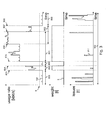
- Fig. 1 schematically illustrates a view of a Digital Subscriber Line data usage rate 10 during for example a 24h period of time 11 with 15-min polling period and the presence of errors 12 during the same 24h period 11.
- an end-user starts using the Digital Subscriber Line and the usage rate 10 starts increasing.
- an IPTV-High Definition stream 15 also referred to as IPTV-HD stream 15
- IPTV-SD 17 is also launched.
- the first stream 15 is turned off at the time 18 and at the time 19, the second stream 17 is turned off as well.
- the second stream 17 then lasted over the period 20.
- the modem is always in showtime during this period 11.
- the MTBE is evaluated to be equal to 2215s, or 36min.
- the threshold ⁇ s from the relation (4) is equal to 20min, the line will be classified as stable, even though the QoS of the end-user is very low.
- the calculation of the MTBE does not reflect the degraded QoS. The impact of errors 12 on the QoS is therefore not evaluated and the stability assessment is not correctly estimated.
- a device for estimating the stability of a Digital Subscriber Line comprising:
- the device allows a more accurate estimation of the stability of a Digital Subscriber Line, which is further also referred to as line.
- the usage of the Digital Subscriber Line over time may be represented by the usage rate of the Digital Subscriber Line, i.e. the amount of data in bits transmitted over the Digital Subscriber Line per unit of time, and the usage rate is monitored over time. The usage rate is taken into account in the estimation of the stability of the Digital Subscriber Line.
- An automatic monitoring of the activity on the line allows to collect information about the usage rate of the line over time.
- a line may classified as stable, risky or unstable based on the result of the comparison of metrics characterizing the line to predetermined thresholds. The determination of the metrics by the Mean Time Between Issues unit relies on the monitored usage rate of the line.
- the determination of the weighted Mean Time Between Issues also referred to as Mean Time Between Issues or MTBi throughout this patent application, adaptively weights the importance of issues occurring inside and outside a period of time during which an end-user uses the line, i.e. a period of time when the usage rate is respectively higher than and lower than a predefined usage threshold.
- the Mean Time Between Issues unit adaptively weights the importance of issues depending on the respective impact of these issues on for example the required bandwidths, the Quality of Service, etc. This way, the Mean Time Between Issues more accurately reflects what an end-user of the Digital Subscriber Line really perceives in terms of Quality of Service when the end-user actually uses the Digital Subscriber Line.
- the estimation of the Quality of Service and the estimation of the stability of the Quality of Service reflect what the end-user really experiences during the usage of the Digital Subscriber Line with a significant improved accuracy.
- the device facilitates the decision making in a troubleshooting process such as for example Dynamic Line Management. Indeed, if for instance the Digital Subscriber Line is accurately and rightfully classified as unstable, more reliable and more efficient actions can be taken faster in order to ensure the Digital Subscriber Line becomes and remains stable without unnecessarily risking jeopardizing the Quality of Service of the line.
- steps of the troubleshooting process such as for instance reporting issued lines on which issues occur, identifying issued lines and quantifying the Quality of Service of issued lines, analysing the source of the issues, performing a diagnosis of the issued lines to determine the source of issues, and repairing the issued lines happen faster, more easily, more accurately and more reliably.
- the issues monitored by the Mean Time Between Issues unit are for example code-corrupted errors, re-synchronizations of a modem (for example Customer-Premises Equipment, also referred to as CPE), but also of a cabinet (for example Central Office equipment, also referred to as CO, or a Digital subscriber line access multiplexer, also referred to as DSLAM), code violations, error seconds, error-free throughput level drops, jitters, any suitable combination of the above, any other figure indicative for the stability of the Digital Subscriber Line, etc.
- CPE Customer-Premises Equipment
- CO Central Office equipment
- DSLAM Digital subscriber line access multiplexer
- the Mean Time Between Issues can therefore determine for instance a Mean Time Between Errors, also referred to as MTBE, which is an indication for the mean time a line has to wait before its PHY service is degraded by impacting errors, and/or a Mean Time Between Re-synchronizations, also referred to as MTBR, which is an indication of the mean time before which a modem or a cabinet spontaneously re-synchronizes because of the degraded quality of the transmission along the line, and/or a Mean Time Between Drops, and/or any other suitable metric useful to classify a line as stable, risky or unstable, and/or any combination of two or more of the above metrics.
- MTBE Mean Time Between Errors
- MTBR Mean Time Between Re-synchronizations
- a Mean Time Between Drops and/or any other suitable metric useful to classify a line as stable, risky or unstable, and/or any combination of two or more of the above metrics.
- the Mean Time Between Re-synchronizations is an indication of the re-synchronizations occurring on the communication link.
- the Mean Time Between Drops also referred to as MTBD, is a quantification of the impacting drops of bitrate or throughput or error-free throughput.
- the Mean Time Between Drops is an indication of the number of drops of useful bitrate with no proper errors at the PHY-layer but that however have consequences on the Quality of Service of the line.
- a time window typically extends over a period of 24 hours. Over the time window, several streams can be activated by the end-user of the line. In other words, the usage rate from the Digital Subscriber Line increases with the number of streams.
- the Mean Time Between Issues unit determines a Mean Time Between Issues for each stream occurring during the time window.
- the weights determined from the usage rate and used to determine the weighted time window and the weights determined from the usage rate and used to determine the weighted number of issues are identical. Alternatively, the weights determined from the usage rate and used to determine the weighted time window and the weights determined from the usage rate and used to determine the weighted number of issues are equal to different numerical values in the range of zero to one.
- the usage monitor monitors the usage rate of the Digital Subscriber Line periodically, the polling period for example being equal to 15 minutes, to one hour, to a day, etc.
- the Mean Time Between Issues unit monitors issues occurring on the Digital Subscriber Line periodically, the polling period for example being equal to 15 minutes, to one hour, to a day, etc. This way, the calculation of the Mean Time Between Issues is made accurate and reliable, as the determination of the weights and therefore the determination of the Mean Time Between Issues is periodically updated.
- the usage rate and issues are monitored during the time window.
- the numerator of the MTBi from equation (7) is the weighted time window determined from the time window with one or more weights determined in function of the usage rate.
- the denominator of the MTBi from equation (7) is the weighted number of issues determined from the issues during the time window with one or more weights determined in function of the usage rate.
- the device further comprises a stability classification unit adapted to compare the weighted Mean Time Between Issues calculated with one or more stability thresholds to classify the Digital Subscriber Line as stable or unstable when the weighted Mean Time Between Issues is higher than or lower than said one or more stability thresholds.
- a stability classification unit adapted to compare the weighted Mean Time Between Issues calculated with one or more stability thresholds to classify the Digital Subscriber Line as stable or unstable when the weighted Mean Time Between Issues is higher than or lower than said one or more stability thresholds.
- the stability thresholds are the stability thresholds ⁇ s and ⁇ u from the relations (4), (5) and (6) related to a Mean Time Between Errors, ⁇ s and ⁇ u from the relations (4), (5) and (6) related to a Mean Time Between Re-synchronizations, any suitable combination of the stability thresholds from the relations (4), (5) and (6), any other suitable stability threshold related to a Mean Time Between Issues and used to classify a line as stable, risky, unstable, etc.
- the stability thresholds are determined from empirical rules. For example, when watching a video stream such as a movie, it is not acceptable to experience an issue every 2 seconds.
- a stability threshold is then for example set to 1 or 2 hours, or to any other value corresponding to the desire of an Internet and/or telecom service provider.
- the stability thresholds are determined from requirements for the Digital Subscriber Line, from characteristics of the Digital Subscriber Line, etc and depend for example on the Service Level Agreement, on a service quality paid for, etc.
- Thresholds can also be determined after studying the characteristics of a particular network or communication chain of an Internet and/or telecom service provider. In that case, quantitative measurements are performed in order to assess when the Quality of Service is degraded, and are used to set the values of the stability thresholds accordingly. This way, when two Mean Time Between Issues are higher than two first stability thresholds, the Digital Subscriber Line is classified as stable.
- the Digital Subscriber Line is classified as unstable.
- the first stability thresholds and the second stability thresholds are equal to different numerical values.
- the second stability thresholds are a numerical value lower than the value of the first stability thresholds.
- the two first stability thresholds can be equal to the same value.
- the two first stability thresholds are equal to two different numerical values.
- the two second stability thresholds can be equal to the same value.
- the two second stability thresholds are equal to two different numerical values.
- a Digital Subscriber Line can be classified as stable when the MTBE and the MTBR comply with the requirements of the relation (4).
- a Digital Subscriber Line can be classified as unstable when the MTBE and the MTBR comply with the requirements of the relation (6).
- a Digital Subscriber Line can be classified as risky when the MTBE and the MTBR comply with the requirements of the relation (5). This way, steps of troubleshooting can be implemented in a fast manner to for example identify the issues, analyse the source of the issues, repair the issued line, etc.
- a weight associated with a high usage rate is a numerical value higher than a weight associated with a low usage rate.
- an issue occurring on the Digital Subscriber Line when an end-user is using the line i.e. when the usage rate of the line is high, e.g. below a predefined usage threshold, is weighted by a numerical value higher than the numerical value of a weight used to weight an issue occurring on the Digital Subscriber Line when the end-user is not using the line, i.e. when the usage rate of the line is low, e.g. below a predefined usage threshold.
- issues occurring on the Digital Subscriber Line when the end-user is using the line are weighted with a higher value, i.e. are weighted with more importance than issues occurring on the line when the end-user is not using the line.
- the Mean Time Between Issues more accurately reflects what the end-user of the Digital Subscriber Line really perceives in terms of Quality of Service when the end-user actually uses the Digital Subscriber Line.
- the estimation of the Quality of Service and the estimation of the stability of the Quality of Service reflect what the end-user really experiences during the usage of the Digital Subscriber Line with a significant improved accuracy.
- This facilitates the decision making in a troubleshooting process such as for example Dynamic Line Management and the satisfaction of the end-user of the line is greatly improved as actions match the experience of the end-user when the end-user uses the line.
- the one or more weights are numerical values in the range of zero to one.
- the lowest value of one or more of the weights is equal to zero.
- the highest value of one or more of the weights is equal to one.
- the one or more weights are equal to:
- the predefined usage threshold determines a threshold for the usage rate above which a Digital Subscriber Line is considered as under use. When the usage rate is below the predefined usage threshold, the line is considered as not under use.
- the Mean Time Between Issues unit adaptively weights the importance of issues depending on the respective impact of these issues on for example the required bandwidths, the Quality of Service, etc.
- the Mean Time Between Issues adaptively weights the importance of issues depending on the fact that the issues occur inside or outside a period of time during which an end-user uses the line and during which the usage rate is respectively above or below the predefined usage threshold.
- the Mean Time Between Issues more accurately reflects what an end-user of the Digital Subscriber Line really perceives in terms of Quality of Service when the end-user actually uses the Digital Subscriber Line.
- the estimation of the Quality of Service and the estimation of the stability of the Quality of Service reflect what the end-user really experiences during the usage of the Digital Subscriber Line with a significant improved accuracy.
- the one or more weights are proportional to the usage rate.
- the usage rate monitored when two streams are active along the line is higher than the usage rate monitored when only one stream is active along the line.
- the value of the weight used to weight the importance of issues occurring on the Digital Subscriber Line is proportional to the number of streams active along the line. For example, issues occurring on the line when two streams are active are weighted with a weight equal to a value equal to twice the value of a weight used to weight issues occurring on the line when only one stream is active.
- the Mean Time Between Issues unit adaptively weights the importance of issues depending on the respective impact of these issues on for example the required bandwidths, the Quality of Service, etc.
- the Mean Time Between Issues adaptively weights the importance of issues depending on the fact that the issues occur inside or outside a period of time during which an end-user uses the line, but the Mean Time Between Issues also adaptively weights the importance of issues depending on how many streams are active on the Digital Subscriber Line, i.e. on how heavily an end-user uses the line.
- the more an end-user uses the line the more impact issues occurring on the line during this period of time have and the more importance the issues have in the calculation of the Mean Time Between Issues.
- the estimation of the Quality of Service and the estimation of the stability of the Quality of Service reflect what the end-user really experiences during the usage of the Digital Subscriber Line with a significant improved accuracy.
- the satisfaction of the end-user of the line is greatly improved as troubleshooting actions match the experience of the end-user when the end-user uses the line.
- the weighted Mean Time Between Re-synchronizations also referred to as Mean Time Between Re-synchronizations or MTBR throughout this patent application, is compared to stability thresholds.
- Mean Time Between Issues different from the Mean Time Between Re-synchronizations, and the Mean Time Between Re-synchronizations comply with the requirements of relation (4)
- the Digital Subscriber Line is classified as stable.
- Mean Time Between Issues and the Mean Time Between Re-synchronizations comply with the requirements of relation (6)
- the Digital Subscriber Line is classified as unstable.
- the Digital Subscriber Line is classified as risky. This way, the estimation of the stability of the Digital Subscriber Line is made more accurate and reliable as the estimation is based on several figures, e.g. the MTBi and the MTBR, and therefore takes more measured parameters and characteristics of the line and the usage rate into account.
- MTBR ⁇ t T weight t . T p ⁇ t T weight t . synchronizations t
- T p the showtime during the polling period
- T the time window.
- the usage rate and re-synchronizations are monitored during the time window.
- the numerator of the MTBR from equation (8) is the weighted time window determined from the time window with one or more weights determined in function of the usage rate.
- the denominator of the MTBR from equation (8) is the weighted duration between two consecutive re-synchronizations, referred to as synchronizations [ t ] , determined from the re-synchronizations during the time window with one or more weights determined in function of the usage rate.
- normalized usage rate t usage rate t ⁇ t T usage rate t
- T is the time window
- usage rate is the usage rate monitored during the time window.
- nMBTi a normalized weighted Mean Time Between Issues
- Tp the showtime during the polling period and where T is the time window.
- the usage rate and issues are monitored during the time window.
- the numerator of the nMTBi from equation (10) is the weighted time window determined from the time window with one or more weights determined in function of the usage rate.
- the denominator of the nMTBi from equation (10) is the normalized weighted number of issues determined from the issues during the time window with one or more weights determined in function of the normalized usage rate.
- normalized usage rate t usage rate t ⁇ t T usage rate t
- T is the time window
- usage rate is the usage rate monitored during the time window.
- nMBTR a normalized weighted Mean Time Between Re-synchronization
- T p the showtime during the polling period and where T is the time window.
- the usage rate and issues are monitored during the time window.
- the numerator of the nMTBR from equation (12) is the weighted time window determined from the time window with one or more weights determined in function of the usage rate.
- the denominator of the nMTBR from equation (12) is the normalized weighted duration between two consecutive re-synchronizations, referred to as synchronizations [ t ] , determined from the re-synchronizations during the time window with one or more weights determined in function of the normalized usage rate.
- the Mean Time Between Issues unit is adapted to skip the determination of the weighted time window and the corresponding weighted number of issues when the usage rate is below a predefined usage rate threshold during one or more corresponding time windows.
- the device is able to identify one or more time windows during which the usage rate is always lower than a predefined usage rate threshold.
- This is an indication that an end-user of the Digital Subscriber Line is not using the line.
- the predefined usage rate threshold may be substantially equal to or equal to the predefined usage threshold. Skipping the determination of the weighted time window and the corresponding weighted number of issues is therefore relevant as issues occurring during these one or more time windows do not have an impact on the perceived experience of the end-user of the line. The action of skipping the calculation saves computational power, and therefore reduces the costs associated with the implementation of the device.
- a method for estimating the stability of a Digital Subscriber Line comprising the steps of:
- the method allows a more accurate estimation of the stability of a Digital Subscriber Line, which is also referred to as line.
- the usage of the Digital Subscriber Line over time may be represented by the usage rate of the Digital Subscriber Line, i.e. the amount of data in bits transmitted over the Digital Subscriber Line per unit of time, and the usage rate is monitored over time. The usage rate is taken into account in the estimation of the stability of the Digital Subscriber Line.
- An automatic monitoring of the activity on the line allows to collect information about the usage rate of the line over time.
- a line may be classified as stable, risky or unstable based on the result of the comparison of metrics characterizing the line to predetermined thresholds.
- the determination of the metrics relies on the monitoring of the usage rate of the line
- the determination of the Mean Time Between Issues also referred to as Mean Time Between Issues or MTBi throughout this patent application, adaptively weights the importance of issues occurring inside and outside a period of time during which an end-user uses the line, i.e. a period of time when the usage rate is respectively higher than and lower than a predefined usage threshold.
- the Mean Time Between Issues unit adaptively weights the importance of issues depending on the respective impact of these issues on for example the required bandwidths, the Quality of Service, etc. This way, issues are adaptively weighted depending on the respective impact of these issues on for example the required bandwidths, the Quality of Service, etc.
- the Mean Time Between Issues more accurately reflects what an end-user of the Digital Subscriber Line really perceives in terms of Quality of Service when the end-user actually uses the Digital Subscriber Line.
- the estimation of the Quality of Service and the estimation of the stability of the Quality of Service reflect what the end-user really experiences during the usage of the Digital Subscriber Line with a significant improved accuracy.
- the device facilitates the decision making in a troubleshooting process such as for example Dynamic Line Management. Indeed, if for instance the Digital Subscriber Line is accurately and rightfully classified as unstable, more reliable and more efficient actions can be taken faster in order to ensure the Digital Subscriber Line becomes and remains stable without unnecessarily risking jeopardizing the Quality of Service of the line.
- steps of the troubleshooting process such as for instance reporting issued lines on which issues occur, identifying issued lines and quantifying the Quality of Service of issued lines, analysing the source of the issues, performing a diagnosis of the issued lines to determine the source of issues, and repairing the issued lines happen faster, more easily, more accurately and more reliably.
- the issues monitored by the Mean Time Between Issues unit are for example code-corrupted errors, re-synchronizations of a modem (for example Customer-Premises Equipment, also referred to as CPE), but also of a cabinet (for example Central Office equipment, also referred to as CO, or a Digital subscriber line access multiplexer, also referred to as DSLAM), code violations, error seconds, error-free throughput level drops, jitters, any suitable combination of the above, any other figure indicative for the stability of the Digital Subscriber Line, etc.
- CPE Customer-Premises Equipment
- CO Central Office equipment
- DSLAM Digital subscriber line access multiplexer
- the Mean Time Between Issues can therefore determine for instance a Mean Time Between Errors, also referred to as MTBE, which is an indication for the mean time a line has to wait before its PHY service is degraded by impacting errors, and/or a Mean Time Between Re-synchronizations, also referred to as MTBR, which is an indication of the mean time before which a modem or a cabinet spontaneously re-synchronizes because of the degraded quality of the transmission along the line, and/or a Mean Time Between Drops, and/or any other suitable metric useful to classify a line as stable, risky or unstable, and/or any combination of two or more of the above metrics.
- MTBE Mean Time Between Errors
- MTBR Mean Time Between Re-synchronizations
- a Mean Time Between Drops and/or any other suitable metric useful to classify a line as stable, risky or unstable, and/or any combination of two or more of the above metrics.
- the Mean Time Between Re-synchronizations is an indication of the re-synchronizations occurring on the communication link.
- the Mean Time Between Drops also referred to as MTBD, is a quantification of the impacting drops of bitrate or throughput or error-free throughput.
- the Mean Time Between Drops is an indication of the number of drops of useful bitrate with no proper errors at the PHY-layer but that however have consequences on the Quality of Service of the line.
- a time window typically extends over a period of 24 hours. Over the time window, several streams can be activated by the end-user of the line. In other words, the usage rate from the Digital Subscriber Line increases with the number of streams.
- Each stream of the time window is characterized by a Mean Time Between Issues.
- the weights determined from the usage rate and used to determine the weighted time window and the weights determined from the usage rate and used to determine the weighted number of issues are identical. Alternatively, the weights determined from the usage rate and used to determine the weighted time window and the weights determined from the usage rate and used to determine the weighted number of issues are equal to different numerical values in the range of zero to one.
- the usage rate of the Digital Subscriber Line is monitored periodically, the polling period for example being equal to 15 minutes, to one hour, to a day, etc. Issues occurring on the Digital Subscriber Line are monitored periodically, the polling period for example being equal to 15 minutes, to one hour, to a day, etc. This way, the calculation of the Mean Time Between Issues is made accurate and reliable, as the determination of the weights and therefore the determination of the Mean Time Between Issues is periodically updated.
- the current invention in addition also relates to a computer program comprising software code adapted to perform the method according to the present invention.
- the invention further relates to a computer readable storage medium comprising the computer program according to the present invention.
- a usage rate 10 of a Digital Subscriber Line is monitored during a 24 hour time window 11. Over this time window 11, the usage rate is monitored every 15 minutes. During the same time window 11 of 24 hours, errors 12 are monitored.
- an end-user starts using the Digital Subscriber Line and the usage rate 10 increases.
- an IPTV-High Definition stream 15 also referred to as IPTV-HD stream 15
- IPTV-SD 17 is also active.
- the first stream 15 is turned off at the time 18 and at the time 19, the second stream 17 is turned off as well.
- the second stream 17 was active during the period 20.
- the CPE is always in showtime during this time window 11.
- 39 errors are measured during the time window 11, and according to the definition, the MTBE is evaluated to be equal to 2215s, or 36min.
- the threshold ⁇ s from the relation (4) is equal to 20min, the line is classified as stable, even though the QoS of the end-user is very low.
- the calculation of the MTBE does not reflect the degraded QoS. The impact of errors 12 on the QoS is therefore not evaluated and the stability assessment is not correctly estimated.
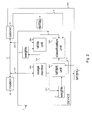
- a device 1 comprises a usage monitor 100 and a Mean Time Between Issues unit 200, labelled MTBi unit.
- a Digital Subscriber Line 2 is positioned between a modem 20, for example a Customer-Premises Equipment, and a cabinet 21, which can for instance be a central office, a digital subscriber line access multiplexer, etc.
- the device 1 optionally comprises a stability classification unit 300 and a Mean Time Between Re-synchronization unit 400.
- the usage monitor 100 monitors a usage rate 101 of a Digital Subscriber Line 2 by a modem 20.
- the Mean Time Between Issues unit 200 monitors issues 201 occurring on the Digital Subscriber Line 2 during the time window.
- the Mean Time Between Issues unit 200 of the device 1 determines a weighted time window from the time window with one or more weights 3 determined in function of the usage rate 101.
- the usage rate 101 is retrieved from the cabinet 21, for example from a management information base or another database of a central office equipment or of a digital line access multiplexer.
- the Mean Time Between Issues unit 200 determines a weighted number of issues from the issues 201 with one or more weights 3 determined in function of the usage rate 101.
- the issues 201 are retrieved from the cabinet 21, for example from a management information base or another database of a central office equipment or of a digital line access multiplexer.
- the Mean Time Between Issues unit 200 determines a Mean Time Between Issues 4 by dividing the weighted time window by the weighted number of issues.
- a stability classification unit 300 compares the Mean Time Between Issues 4 to stability thresholds 5 in order to classify the Digital Subscriber Line 2 as stable or unstable.
- the device 1 further comprises a Mean Time Between Re-synchronizations unit 400.
- the Mean Time Between Re-synchronizations unit 400 monitors re-synchronizations 401 arising from the modem 20 or from the cabinet 21 during the time window.
- the parameters of the re-synchronizations 401 are for example retrieved from a database located in the cabinet 21 such as for example a management information base, also referred to as MIB, of a digital subscriber line access multiplexer.
- the Mean Time Between Re-synchronizations unit 400 monitors the re-synchronizations 401 of arising from the modem 20 during the time window. Additionally, the Mean Time Between Re-synchronizations unit 400 determines a weighted duration between two re-synchronizations from the synchronizations 401 during the time window with one or more weights determined in function of the usage rate 101. Additionally, the Mean Time Between Re-synchronizations unit 400 determines a weighted Mean Time Between Re-synchronizations 7 by dividing the weighted time window by the weighted duration between two re-synchronizations.
- the cabinet 21 comprises the stability thresholds 5. Alternatively, the modem 20 comprises the stability thresholds 5. Alternatively, the stability thresholds are comprised in the device 1.
- the cabinet 21 of Fig. 2 can comprise the device 1 of Fig. 2 .
- the device 1 of Fig. 2 can be comprised in the modem 20 of Fig. 2 .
- the device 1 can be implemented independently from the cabinet 21 and the modem 20.
- the determination of the weights 3 of Fig. 2 is performed by the device 1 of Fig. 2 .
- the determination of the weights 3 of Fig. 2 can be performed by a unit comprised in the cabinet 21, the modem 20, or any other suitable unit.
- the usage rate 101 of a Digital Subscriber Line is monitored during a time window 102.
- the usage rate 101 is the amount of data in bits transmitted over the Digital Subscriber Line per unit of time. Over the time periods 809, the usage rate 201 is below a predefined usage threshold 6.
- a first stream becomes active on the Digital Subscriber Line.
- the first stream stops. The first stream therefore lasts over the period 800.
- the usage rate 101 is above a predefined usage threshold 6 during the period 800.
- a second stream becomes active on the Digital Subscriber Line.
- a third stream becomes active on the Digital Subscriber Line.
- the second stream stops.
- the second stream therefore lasts over the period 801.
- the third stream therefore lasts over the period 802.
- the usage rate 101 is above a predefined usage threshold 6 during the periods 800;801;802.
- issues 201 are monitored during the time window 102.
- Weights 3 are determined in function of the usage rate 101.
- Weights 3 associated with issues 201 occurring on the Digital Subscriber Line during periods during which the usage rate 101 is above the predefined usage threshold 6 are equal to numerical values higher than weights 3 associated with issues 201 occurring on the Digital Subscriber Line during periods during which the usage rate 101 is below the predefined usage threshold 6.
- weights 3 during the periods 800;801;802 are equal, and equal to a numerical value higher than the weights 3 during the periods 809.
- the weights 3 during the period 800 are equal to a numerical value different from the weights 3 during the period 801 and/or the period 802. Issues 201 occurring on the Digital Subscriber Line during the periods 800;801;802 have a larger importance in the determination of the Mean Time Between Issues than the issues 201 occurring on the Digital Subscriber Line during the periods 809, as the first issues 201 are weighted with a larger numerical value.
- the usage rate 101 of a Digital Subscriber Line is monitored during a time window 102.
- the usage rate 101 is the amount of data in bits transmitted over the Digital Subscriber Line per unit of time. Over the time periods 809, the usage rate 101 is below a predefined usage threshold 6.
- a first stream becomes active on the Digital Subscriber Line.
- the usage rate 101 is above a predefined usage threshold 6 during the period 810.
- the first stream is still active on the Digital Subscriber Line, but the usage rate 101 drops below the predefined usage threshold 6.
- the usage rate 101 is below the predefined usage threshold 6.
- the usage rate 101 exceeds the predefined usage threshold 6. Between the times 815 and 816, i.e. during the period 819, the usage rate 101 drops below the predefined usage threshold 6. From the time 816, the usage rate 101 exceeds the predefined usage threshold 6 until the time 817, i.e. over the period 811. After the time 817, the usage rate 101 is below the predefined usage threshold 6. As visible in Fig. 4 , issues 201 are monitored during the time window 102. Weights 3 are determined in function of the usage rate 101.
- Weights 3 associated with issues 201 occurring on the Digital Subscriber Line during periods during which the usage rate 101 is above the predefined usage threshold 6 are equal to numerical values higher than weights 3 associated with issues 201 occurring on the Digital Subscriber Line during periods during which the usage rate 101 is below the predefined usage threshold 6.
- weights 3 during the periods 810;820;811 are equal, and equal to a numerical value higher than the weights 3 during the periods 809;818;819.
- the weights 3 during the period 810 are equal to a numerical value different from the weights 3 during the period 820 and/or the period 811.
- Issues 201 occurring on the Digital Subscriber Line during the periods 810;820;811 have a larger importance in the determination of the Mean Time Between Issues than the issues 201 occurring on the Digital Subscriber Line during the periods 809;818;819, as the first issues 201 are weighted with a larger numerical value.
- a normalized usage rate 103 is determined from a normalization of the usage rate 101 over the time window 102.
- Fig. 5 shows a suitable computing system 700 for hosting the device 1 of Fig. 2 .
- Computing system 700 may in general be formed as a suitable general purpose computer and comprise a bus 510, a processor 502, a local memory 504, one or more optional input interfaces 514, one or more optional output interfaces 516 a communication interface 512, a storage element interface 506 and one or more storage elements 508.
- Bus 510 may comprise one or more conductors that permit communication among the components of the computing system.
- Processor 502 may include any type of conventional processor or microprocessor that interprets and executes programming instructions.
- Local memory 504 may include a random access memory (RAM) or another type of dynamic storage device that stores information and instructions for execution by processor 502 and/or a read only memory (ROM) or another type of static storage device that stores static information and instructions for use by processor 504.
- Input interface 514 may comprise one or more conventional mechanisms that permit an operator to input information to the computing device 800, such as a keyboard 520, a mouse 530, a pen, voice recognition and/or biometric mechanisms, etc.
- Output interface 516 may comprise one or more conventional mechanisms that output information to the operator, such as a display 540, a printer 550, a speaker, etc.
- Communication interface 512 may comprise any transceiver-like mechanism such as for example two 1 Gb Ethernet interfaces that enables computing system 800 to communicate with other devices and/or systems, for example mechanisms for communicating with one or more other computing systems 900.
- the communication interface 512 of computing system 700 may be connected to such another computing system by means of a local area network (LAN) or a wide area network (WAN, such as for example the internet, in which case the other computing system 580 may for example comprise a suitable web server.
- LAN local area network
- WAN wide area network
- the other computing system 580 may for example comprise a suitable web server.
- Storage element interface 506 may comprise a storage interface such as for example a Serial Advanced Technology Attachment (SATA) interface or a Small Computer System Interface (SCSI) for connecting bus 510 to one or more storage elements 508, such as one or more local disks, for example 1 TB SATA disk drives, and control the reading and writing of data to and/or from these storage elements 508.
- SATA Serial Advanced Technology Attachment
- SCSI Small Computer System Interface
- the storage elements 508 above is described as a local disk, in general any other suitable computer-readable media such as a removable magnetic disk, optical storage media such as a CD or DVD, -ROM disk, solid state drives, flash memory cards, ... could be used.
- the system 700 described above can also run as a Virtual Machine above the physical hardware.
- the device 1 of Fig. 2 can be implemented as programming instructions stored in local memory 504 of the computing system 700 for execution by its processor 502.
- device 1 of Fig. 2 could be stored on the storage element 508 or be accessible from another computing system 900 through the communication interface 512.
- top, bottom, over, under, and the like are introduced for descriptive purposes and not necessarily to denote relative positions. It is to be understood that the terms so used are interchangeable under appropriate circumstances and embodiments of the invention are capable of operating according to the present invention in other sequences, or in orientations different from the one(s) described or illustrated above.
Landscapes
- Engineering & Computer Science (AREA)
- Signal Processing (AREA)
- Computer Networks & Wireless Communication (AREA)
- Quality & Reliability (AREA)
- Monitoring And Testing Of Exchanges (AREA)
- Telephonic Communication Services (AREA)
- Data Exchanges In Wide-Area Networks (AREA)
Abstract
- a usage monitor (100) monitoring a usage rate (101) of said DSL (2);
- a Mean Time Between Issues unit (200):
- monitoring issues (201);
- determining a weighted time window (202) with weights determined in function of said usage rate (101);
- determining a weighted number of issues (203) with weights determined in function of said usage rate (101); and
- determining a weighted Mean Time Between Issues (4) by dividing said weighted time window (202) by said weighted number of issues (203).
Description
- The present invention relates to the field of troubleshooting to optimize the performances of the physical or PHY-layer, especially for Digital Subscriber Lines.
- With the increasing deployment of Internet Protocol Television, also referred to as IPTV solutions, Video-On-Demand offers or Triple-play services, the requirements on both the performances of the system and the customer support become more and more demanding, particularly on Digital Subscriber Lines, also referred to as DSL. The physical link which transports information through wire lines up to the end-user is known to be the bottleneck for the Quality of Service, also referred to as QoS. Additionally, the signal bandwidth of the DSL lines is pushed higher and higher. For example, traditional ADSL technology was using frequencies up to 1.1 MHz, and the current VDSL2 technology can be applied up to 17 or even 30MHz. The extensive use of those higher frequencies as well as more and more advanced solutions to increase the performances of the DSL make the DSL link more sensitive to disturbances, for example to interferences with other devices functioning at frequencies close to the ones of the DSL.
- Troubleshooting is the identification or diagnosis of trouble in the management or data flow of a system such as for example a Digital Subscriber Line caused by a failure of some kind. The problem is initially described as a symptom of malfunctioning, and troubleshooting is the process of determining and remedying the causes of these symptom. In the context of Digital Subscriber Lines, troubleshooting improves the action of reporting issues occurring on a line, for which the Quality of Service, perceived or not by an end-user, is consequently degraded. Troubleshooting allows to diagnose one or more events generating the issues on the line. For example, within a pro-active context, troubleshooting aims at identifying the reasons of a possible degradation of the Quality of Service for an end-user before the degradation actually impacts his Quality of Service. Additionally, the troubleshooting process allows to quantify the impact of the identified issues for an end-user of the line. In order to improve the experience of the end-user by improving the Quality of Service of a line, a manual intervention can be performed on the line but requires the intervention of a skilled technician and is not always necessary. An alternative to a manual intervention is for example Dynamic Line Management.
- Dynamic Line Management, also referred to as DLM, allows to monitor the performances of the line and to take actions in order to provide a better QoS of the PHY-layer. The DLM consists in dynamically assessing and monitoring the stability of a line in order to take the most suitable action on the PHY parameters to guarantee the stability of the line and to provide the line with the highest bitrate performances under this stable condition. If a fairly stable line is classified as unstable, although the end-user does not feel any practical impacts on its QoS, the DLM will take actions leading to a reduction of the bitrate and/or a lowering of the reactivity of the line. This dramatically decreases the QoS of the offered experience perceived by an end-user. In this case, the satisfaction of the end-user is not improved.
- To assess the QoS of a line, i.e. to establish if a line is stable or not, metrics and thresholds have been arbitrary defined from empirical rules. These metrics are computed as the Mean Time Between Errors, also referred to as MTBE, and the Mean Time Between Re-synchronizations, also referred to as MTBR and the classification is performed using thresholds. The MTBE and the MTBR can be split between the Downstream and the Upstream directions, but they can also be merged. For example, information indicative for the MTBE and the MTBR can be defined and comprise a union, a sum value, an average value, etc of the two metrics. The MTBE is an indication of the mean time that a line has to wait before its PHY service is being degraded by corrupted symbols, i.e. by PHY symbols containing impacting errors, for example because of impulse noise. The MTBR is an indication of the mean time before a modem spontaneously synchronizes again because of the weak quality of the link. As these metrics are directly used by the DLM, the offered bitrates are directly related to them. The MTBE and the MTBR are defined as follows:


- where T is the time window during the data, such as the amount of Code Violations, referred to as CV in equation (3), the Error Seconds, referred to as ES in equation (3), the Severely Errored Seconds, referred to as SES in equation (3), the amount of showtime, or the amount of spontaneous re-synchronizations are monitored. When a signal is corrupted, a Code Violation is reported. ES is the number of seconds during which one or more non-remedial errors have occurred. SES is the number of times when a given number of consecutive Errored Seconds has been measured. Θs , Θu , Γs , and Γu are stability thresholds to which the MTBE and the MTBR are compared to estimate if a line is stable, illustrated by relations (4), risky, illustrated by relation (5) or unstable, illustrated by relation (6). In equation (3), ω 1, ω 2, ω 3 are weights which can take any suitable numerical value. The weights are used to attribute more importance in the calculation of the MTBE to the CV, the ES and/or the SES. If for example there are more Code Violations than there are Errored Seconds or Severely Errored Seconds, Code Violations will be associated with a heavier weight than ES and SES, so that the calculation of the MTBE is primarily determined by the amount of Code Violations. The MTBE and MTBR metrics are typically estimated on a daily basis. Burst errors occurring during the night therefore have a similar effect on the estimation of the stability of a line than errors occurring during the day or even during the evening. In other words, if large amount of errors counted during a period of the day are averaged with very few errors counted during another period of the day, the calculated MTBE is significantly low while the end-user might not have perceived any reduced QoS. Such degraded classification in the context of DLM generally leads to for example larger latency or even bitrate reduction. This means that even though the QoS of the end-user was fine and did not require any limitations of for example the bitrate, the DLM results in a degradation of the experience of the end-used as well as a degradation of the performances of the line. With this calculation method of the two metrics, it is also possible to be faced with an opposite classification which also has dramatic effects on the QoS of the end-user. Indeed, a line can be classified as stable even though burst of errors occur during a period of the day. Because of the averaging during the calculation of the MTBE and the MTBR, the line is however classified as stable, even though the QoS of the end-used is significantly low, and the DLM does not provide action to increase the QoS. The estimation of the two metrics MTBE and MTBR is therefore calculated regardless of the impacts of the errors on the experience perceived by the end-user. The calculation is not accurate nor reliable enough to estimate if a line is stable or unstable.
-
Fig. 1 schematically illustrates a view of a Digital Subscriber Linedata usage rate 10 during for example a 24h period oftime 11 with 15-min polling period and the presence oferrors 12 during thesame 24h period 11. At thetime 13, an end-user starts using the Digital Subscriber Line and theusage rate 10 starts increasing. During theperiod 14, an IPTV-High Definition stream 15, also referred to as IPTV-HD stream 15, is launched. At thetime 16, a second IPTV-Standard Definition stream 17, also referred to as IPTV-SD 17, is also launched. Then thefirst stream 15 is turned off at thetime 18 and at thetime 19, thesecond stream 17 is turned off as well. Thesecond stream 17 then lasted over theperiod 20. The modem is always in showtime during thisperiod 11. 39 errors are measured during 24-hours time 11, and according to the definition, the MTBE is evaluated to be equal to 2215s, or 36min. For example, if the threshold Θs from the relation (4) is equal to 20min, the line will be classified as stable, even though the QoS of the end-user is very low. In other words, although the perceived QoS of the end-user was degraded during theperiod 11, the calculation of the MTBE does not reflect the degraded QoS. The impact oferrors 12 on the QoS is therefore not evaluated and the stability assessment is not correctly estimated. - To tackle this issue, other solutions propose to either define black zones or to reject some "outlying periods" of the estimation of the QoS. However, limiting the estimation period to a given period of a day makes the classification blind with respect to all the other periods of the day. Bursts of errors could be present during the neglected time periods, during which errors could really impact the QoS of an end-user. This results in a misclassification of the line, which can be classified as stable while the real QoS of the end-user was in practice degraded. Additionally, as each end-user follows different habits, the calculation relying on rejected time periods is not reliable nor flexible as some end-users use the line during different time periods than other end-users.
- It is an objective to disclose a device and the related method that overcome the above identified shortcomings of existing solutions. More particularly, it is an objective to disclose such a device and method for estimating the stability of a Digital Subscriber Line, where the estimation reliably, accurately and objectively reflects what an end-user of the Digital Subscriber Line perceives in terms of Quality of Service when using the Digital Subscriber Line. It is a further objective to disclose such a device to gain in service quality, to guarantee the highest performances of the Digital Subscriber Line and to improve the Quality of Service of an end-user of the Digital Subscriber Line, while reducing the costs and saving time. It is a further objective to disclose such a device that estimates the stability of a Digital Subscriber Line in a flexible, reliable and efficient manner in order to facilitate a suitable decision making during Dynamic Line Management.
- According to embodiments of the present invention, the above defined objectives are realized by a device for estimating the stability of a Digital Subscriber Line, the device comprising:
- a usage monitor adapted to monitor a usage rate of the Digital Subscriber Line during at least one time window;
- a Mean Time Between Issues unit adapted to:
- monitor issues occurring on the Digital Subscriber Line during the at least one time window;
- determine a weighted time window from the at least one time window with one or more weights determined in function of the usage rate;
- determine a weighted number of issues from the issues monitored during the at least one time window with one or more weights determined in function of the usage rate; and
- determine a weighted Mean Time Between Issues by dividing the weighted time window by the weighted number of issues.
- In accordance with the present invention, the device allows a more accurate estimation of the stability of a Digital Subscriber Line, which is further also referred to as line. The usage of the Digital Subscriber Line over time may be represented by the usage rate of the Digital Subscriber Line, i.e. the amount of data in bits transmitted over the Digital Subscriber Line per unit of time, and the usage rate is monitored over time. The usage rate is taken into account in the estimation of the stability of the Digital Subscriber Line. An automatic monitoring of the activity on the line allows to collect information about the usage rate of the line over time. A line may classified as stable, risky or unstable based on the result of the comparison of metrics characterizing the line to predetermined thresholds. The determination of the metrics by the Mean Time Between Issues unit relies on the monitored usage rate of the line. Indeed, the determination of the weighted Mean Time Between Issues, also referred to as Mean Time Between Issues or MTBi throughout this patent application, adaptively weights the importance of issues occurring inside and outside a period of time during which an end-user uses the line, i.e. a period of time when the usage rate is respectively higher than and lower than a predefined usage threshold. In other words, the Mean Time Between Issues unit adaptively weights the importance of issues depending on the respective impact of these issues on for example the required bandwidths, the Quality of Service, etc. This way, the Mean Time Between Issues more accurately reflects what an end-user of the Digital Subscriber Line really perceives in terms of Quality of Service when the end-user actually uses the Digital Subscriber Line. In other words, the estimation of the Quality of Service and the estimation of the stability of the Quality of Service reflect what the end-user really experiences during the usage of the Digital Subscriber Line with a significant improved accuracy.
- The device according to the present invention facilitates the decision making in a troubleshooting process such as for example Dynamic Line Management. Indeed, if for instance the Digital Subscriber Line is accurately and rightfully classified as unstable, more reliable and more efficient actions can be taken faster in order to ensure the Digital Subscriber Line becomes and remains stable without unnecessarily risking jeopardizing the Quality of Service of the line. Several steps of the troubleshooting process, such as for instance reporting issued lines on which issues occur, identifying issued lines and quantifying the Quality of Service of issued lines, analysing the source of the issues, performing a diagnosis of the issued lines to determine the source of issues, and repairing the issued lines happen faster, more easily, more accurately and more reliably. For example, automatic diagnosis or management systems such as Network Access Control, Dynamic Line Management, etc, directly benefit from this improved estimation of the stability of the line and therefore result in more suitable actions. The satisfaction of the end-user of the line is greatly improved as troubleshooting actions match the experience of the end-user when the end-user actually uses the line.
- The issues monitored by the Mean Time Between Issues unit are for example code-corrupted errors, re-synchronizations of a modem (for example Customer-Premises Equipment, also referred to as CPE), but also of a cabinet (for example Central Office equipment, also referred to as CO, or a Digital subscriber line access multiplexer, also referred to as DSLAM), code violations, error seconds, error-free throughput level drops, jitters, any suitable combination of the above, any other figure indicative for the stability of the Digital Subscriber Line, etc. The Mean Time Between Issues can therefore determine for instance a Mean Time Between Errors, also referred to as MTBE, which is an indication for the mean time a line has to wait before its PHY service is degraded by impacting errors, and/or a Mean Time Between Re-synchronizations, also referred to as MTBR, which is an indication of the mean time before which a modem or a cabinet spontaneously re-synchronizes because of the degraded quality of the transmission along the line, and/or a Mean Time Between Drops, and/or any other suitable metric useful to classify a line as stable, risky or unstable, and/or any combination of two or more of the above metrics. As a re-synchronization can arise for example from a modem or from a cabinet, for example generated because of an issue in the modem and/or in the cabinet, the Mean Time Between Re-synchronizations is an indication of the re-synchronizations occurring on the communication link. The Mean Time Between Drops, also referred to as MTBD, is a quantification of the impacting drops of bitrate or throughput or error-free throughput. In other words, The Mean Time Between Drops is an indication of the number of drops of useful bitrate with no proper errors at the PHY-layer but that however have consequences on the Quality of Service of the line.
- A time window typically extends over a period of 24 hours. Over the time window, several streams can be activated by the end-user of the line. In other words, the usage rate from the Digital Subscriber Line increases with the number of streams. The Mean Time Between Issues unit determines a Mean Time Between Issues for each stream occurring during the time window. The weights determined from the usage rate and used to determine the weighted time window and the weights determined from the usage rate and used to determine the weighted number of issues are identical. Alternatively, the weights determined from the usage rate and used to determine the weighted time window and the weights determined from the usage rate and used to determine the weighted number of issues are equal to different numerical values in the range of zero to one. The usage monitor monitors the usage rate of the Digital Subscriber Line periodically, the polling period for example being equal to 15 minutes, to one hour, to a day, etc. The Mean Time Between Issues unit monitors issues occurring on the Digital Subscriber Line periodically, the polling period for example being equal to 15 minutes, to one hour, to a day, etc. This way, the calculation of the Mean Time Between Issues is made accurate and reliable, as the determination of the weights and therefore the determination of the Mean Time Between Issues is periodically updated.
- For each stream, a weighted Mean Time Between Issues is calculated as follows:

where Tp is the showtime during the polling period and where T is the time window. The usage rate and issues are monitored during the time window. The numerator of the MTBi from equation (7) is the weighted time window determined from the time window with one or more weights determined in function of the usage rate. The denominator of the MTBi from equation (7) is the weighted number of issues determined from the issues during the time window with one or more weights determined in function of the usage rate. - According to an optional embodiment, the device further comprises a stability classification unit adapted to compare the weighted Mean Time Between Issues calculated with one or more stability thresholds to classify the Digital Subscriber Line as stable or unstable when the weighted Mean Time Between Issues is higher than or lower than said one or more stability thresholds.
- The stability thresholds are the stability thresholds Θs and Θu from the relations (4), (5) and (6) related to a Mean Time Between Errors, Γs and Γu from the relations (4), (5) and (6) related to a Mean Time Between Re-synchronizations, any suitable combination of the stability thresholds from the relations (4), (5) and (6), any other suitable stability threshold related to a Mean Time Between Issues and used to classify a line as stable, risky, unstable, etc. The stability thresholds are determined from empirical rules. For example, when watching a video stream such as a movie, it is not acceptable to experience an issue every 2 seconds. A stability threshold is then for example set to 1 or 2 hours, or to any other value corresponding to the desire of an Internet and/or telecom service provider. Alternatively, the stability thresholds are determined from requirements for the Digital Subscriber Line, from characteristics of the Digital Subscriber Line, etc and depend for example on the Service Level Agreement, on a service quality paid for, etc. Thresholds can also be determined after studying the characteristics of a particular network or communication chain of an Internet and/or telecom service provider. In that case, quantitative measurements are performed in order to assess when the Quality of Service is degraded, and are used to set the values of the stability thresholds accordingly. This way, when two Mean Time Between Issues are higher than two first stability thresholds, the Digital Subscriber Line is classified as stable. When two Mean Time Between Issues are lower than two second stability thresholds, the Digital Subscriber Line is classified as unstable. The first stability thresholds and the second stability thresholds are equal to different numerical values. The second stability thresholds are a numerical value lower than the value of the first stability thresholds. The two first stability thresholds can be equal to the same value. Alternatively, the two first stability thresholds are equal to two different numerical values. The two second stability thresholds can be equal to the same value. Alternatively, the two second stability thresholds are equal to two different numerical values. When the Mean Time Between Issues is comprised between the first stability threshold and the second stability threshold, the Digital Subscriber Line is classified as risky. In other words, there exists a risk for the Digital Subscriber Line to later be classified as unstable if the number of issues occurring on the Digital Subscriber Line degrades the Quality of Service when the end-user of the Digital Subscriber Line is using the line and therefore results in a Mean Time Between Issues lower than the second stability threshold. For example, a Digital Subscriber Line can be classified as stable when the MTBE and the MTBR comply with the requirements of the relation (4). Alternatively, a Digital Subscriber Line can be classified as unstable when the MTBE and the MTBR comply with the requirements of the relation (6). Alternatively, a Digital Subscriber Line can be classified as risky when the MTBE and the MTBR comply with the requirements of the relation (5). This way, steps of troubleshooting can be implemented in a fast manner to for example identify the issues, analyse the source of the issues, repair the issued line, etc.
- According to an optional embodiment, in said one or more weights, a weight associated with a high usage rate is a numerical value higher than a weight associated with a low usage rate.
- This way, an issue occurring on the Digital Subscriber Line when an end-user is using the line, i.e. when the usage rate of the line is high, e.g. below a predefined usage threshold, is weighted by a numerical value higher than the numerical value of a weight used to weight an issue occurring on the Digital Subscriber Line when the end-user is not using the line, i.e. when the usage rate of the line is low, e.g. below a predefined usage threshold. In other words, issues occurring on the Digital Subscriber Line when the end-user is using the line are weighted with a higher value, i.e. are weighted with more importance than issues occurring on the line when the end-user is not using the line. This way, the Mean Time Between Issues more accurately reflects what the end-user of the Digital Subscriber Line really perceives in terms of Quality of Service when the end-user actually uses the Digital Subscriber Line. In other words, the estimation of the Quality of Service and the estimation of the stability of the Quality of Service reflect what the end-user really experiences during the usage of the Digital Subscriber Line with a significant improved accuracy. This facilitates the decision making in a troubleshooting process such as for example Dynamic Line Management and the satisfaction of the end-user of the line is greatly improved as actions match the experience of the end-user when the end-user uses the line.
- According to an optional embodiment, the one or more weights are numerical values in the range of zero to one.
- This way, the values of the weights used to weight issues occurring on the Digital Subscriber Line are normalized. The lowest value of one or more of the weights is equal to zero. The highest value of one or more of the weights is equal to one.
- According to an optional embodiment, the one or more weights are equal to:
- zero when the usage rate is lower than a predefined usage threshold; and
- one when the usage rate is higher than a predefined usage threshold.
- The predefined usage threshold determines a threshold for the usage rate above which a Digital Subscriber Line is considered as under use. When the usage rate is below the predefined usage threshold, the line is considered as not under use. This way, the Mean Time Between Issues unit adaptively weights the importance of issues depending on the respective impact of these issues on for example the required bandwidths, the Quality of Service, etc. This way, the Mean Time Between Issues adaptively weights the importance of issues depending on the fact that the issues occur inside or outside a period of time during which an end-user uses the line and during which the usage rate is respectively above or below the predefined usage threshold. This way, the Mean Time Between Issues more accurately reflects what an end-user of the Digital Subscriber Line really perceives in terms of Quality of Service when the end-user actually uses the Digital Subscriber Line. In other words, the estimation of the Quality of Service and the estimation of the stability of the Quality of Service reflect what the end-user really experiences during the usage of the Digital Subscriber Line with a significant improved accuracy.
- According to an optional embodiment, the one or more weights are proportional to the usage rate.
- This way, the higher the number of active streams on the Digital Subscriber Line is, the higher the usage rate of the line is. For example, the usage rate monitored when two streams are active along the line is higher than the usage rate monitored when only one stream is active along the line. The value of the weight used to weight the importance of issues occurring on the Digital Subscriber Line is proportional to the number of streams active along the line. For example, issues occurring on the line when two streams are active are weighted with a weight equal to a value equal to twice the value of a weight used to weight issues occurring on the line when only one stream is active. This way, the Mean Time Between Issues unit adaptively weights the importance of issues depending on the respective impact of these issues on for example the required bandwidths, the Quality of Service, etc. This way, the Mean Time Between Issues adaptively weights the importance of issues depending on the fact that the issues occur inside or outside a period of time during which an end-user uses the line, but the Mean Time Between Issues also adaptively weights the importance of issues depending on how many streams are active on the Digital Subscriber Line, i.e. on how heavily an end-user uses the line. In other words, the more an end-user uses the line, the more impact issues occurring on the line during this period of time have and the more importance the issues have in the calculation of the Mean Time Between Issues. The estimation of the Quality of Service and the estimation of the stability of the Quality of Service reflect what the end-user really experiences during the usage of the Digital Subscriber Line with a significant improved accuracy. The satisfaction of the end-user of the line is greatly improved as troubleshooting actions match the experience of the end-user when the end-user uses the line.
- According to an optional embodiment:
- the device further comprises a Mean Time Between Re-synchronizations unit adapted to monitor re-synchronizations on the Digital Subscriber Line;
and the Mean Time Between Re-synchronizations unit is further adapted to determine: - a weighted duration between two consecutive re-synchronizations from the re-synchronizations during the at least one time window with one or more weights determined in function of the usage rate; and
- a weighted Mean Time Between Re-synchronizations by dividing the at least one weighted time window by the weighted duration between two consecutive re-synchronizations.
- This way, re-synchronizations arising from a modem or a cabinet are taken into account in the estimation of the stability of a Digital Subscriber Line. The re-synchronization of the communication link is then taken into account in the estimation of the stability of the line. The weighted Mean Time Between Re-synchronizations, also referred to as Mean Time Between Re-synchronizations or MTBR throughout this patent application, is compared to stability thresholds. When a Mean Time Between Issues, different from the Mean Time Between Re-synchronizations, and the Mean Time Between Re-synchronizations comply with the requirements of relation (4), the Digital Subscriber Line is classified as stable. When the Mean Time Between Issues and the Mean Time Between Re-synchronizations comply with the requirements of relation (6), the Digital Subscriber Line is classified as unstable. When the Mean Time Between Issues and the Mean Time Between Re-synchronizations comply with the requirements of relation (5), the Digital Subscriber Line is classified as risky. This way, the estimation of the stability of the Digital Subscriber Line is made more accurate and reliable as the estimation is based on several figures, e.g. the MTBi and the MTBR, and therefore takes more measured parameters and characteristics of the line and the usage rate into account.
- For each stream, a weighted Mean Time Between Re-synchronization is calculated as follows:

where Tp is the showtime during the polling period and where T is the time window. The usage rate and re-synchronizations are monitored during the time window. The numerator of the MTBR from equation (8) is the weighted time window determined from the time window with one or more weights determined in function of the usage rate. The denominator of the MTBR from equation (8) is the weighted duration between two consecutive re-synchronizations, referred to as synchronizations[t], determined from the re-synchronizations during the time window with one or more weights determined in function of the usage rate. - According to an optional embodiment:
- the usage monitor is further adapted to normalize the usage rate over the at least one time window, thereby generating a normalized usage rate;
- the Mean Time Between Issues unit is further adapted to determine:
- a normalized weighted number of issues from the issues monitored during the at least one time window with one or more weights determined in function of the normalized usage rate; and
- a normalized weighted Mean Time Between Issues by dividing the weighted time window by the normalized weighted number of issues.
- During the period of time during which an end-user uses a Digital Subscriber Line, there exist periods of time where the need of bitrate is higher and a need for a good Quality of Service is critical. It is for example the case when several streams are active together along the Digital Subscriber Line. Issues occurring during the active streams could lead to a propagation of issues over the different services and result in a drastic degradation of the overall Quality of Service for the end-user. A normalization of the usage rate is then performed in order to use the normalized usage rate as weights in the calculation of the Mean Time Between Issues, for example in the calculation of a Mean Time Between Errors. This way, the estimation of the Quality of Service is self-adaptive to the usage rate of the Digital Subscriber Line and to the service the end-user is really experiencing. The issues are weighted so as to adaptively weight their importance according to their respective impact on the required bandwidth and/or services.
- The normalized usage rate is determined according to equation (9):

- For each stream, a normalized weighted Mean Time Between Issues, referred to as nMBTi in equation (10) is calculated as follows:

where Tp is the showtime during the polling period and where T is the time window. The usage rate and issues are monitored during the time window. The numerator of the nMTBi from equation (10) is the weighted time window determined from the time window with one or more weights determined in function of the usage rate. The denominator of the nMTBi from equation (10) is the normalized weighted number of issues determined from the issues during the time window with one or more weights determined in function of the normalized usage rate. - According to an optional embodiment:
- the usage monitor is further adapted to normalize the usage rate over the at least one time window, thereby generating a normalized usage rate;
- the Mean Time Between Re-synchronization unit is further adapted to determine:
- a normalized weighted duration between two consecutive re-synchronizations from the re-synchronizations during the at least one time window with one or more weights determined in function of the normalized usage rate; and
- a normalized weighted Mean Time Between Re-synchronizations by dividing the weighted time window by the normalized weighted duration between two consecutive re-synchronizations.
- During the period of time during which an end-user uses a Digital Subscriber Line, there exist periods of time when the need of bitrate is higher and a need for a good Quality of Service is critical. It is for example the case when several streams are active together along the Digital Subscriber Line. Re-synchronizations occurring during the active streams could lead to the propagation of issues over the different services and drastically degrade the overall Quality of Service for the end-user. A normalization of the usage rate is then performed in order to use the normalized usage rate as weights in the calculation of the Mean Time Between Re-synchronizations. This way, the estimation of the Quality of Service is self-adaptive to the usage rate of the Digital Subscriber Line and to the service the end-user is really experiencing. The re-synchronizations are weighted so as to adaptively weight their importance according to their respective impact on the required bandwidth and/or services.
- The normalized usage rate is determined according to equation (11):

where T is the time window, and usage rate is the usage rate monitored during the time window. - For each stream, a normalized weighted Mean Time Between Re-synchronization, referred to as nMBTR in equation (12) is calculated as follows:

where Tp is the showtime during the polling period and where T is the time window. The usage rate and issues are monitored during the time window. The numerator of the nMTBR from equation (12) is the weighted time window determined from the time window with one or more weights determined in function of the usage rate. The denominator of the nMTBR from equation (12) is the normalized weighted duration between two consecutive re-synchronizations, referred to as synchronizations[t], determined from the re-synchronizations during the time window with one or more weights determined in function of the normalized usage rate. - According to an optional embodiment, the Mean Time Between Issues unit is adapted to skip the determination of the weighted time window and the corresponding weighted number of issues when the usage rate is below a predefined usage rate threshold during one or more corresponding time windows.
- This way, the device is able to identify one or more time windows during which the usage rate is always lower than a predefined usage rate threshold. This is an indication that an end-user of the Digital Subscriber Line is not using the line. The predefined usage rate threshold may be substantially equal to or equal to the predefined usage threshold. Skipping the determination of the weighted time window and the corresponding weighted number of issues is therefore relevant as issues occurring during these one or more time windows do not have an impact on the perceived experience of the end-user of the line. The action of skipping the calculation saves computational power, and therefore reduces the costs associated with the implementation of the device.
- According to embodiments of the present invention, there is provided a method for estimating the stability of a Digital Subscriber Line, the method comprising the steps of:
- monitoring a usage rate of the Digital Subscriber Line during at least one time window;
- monitoring issues occurring on the Digital Subscriber Line during the at least one time window;
- determining a weighted time window from the at least one time window with one or more weights determined in function of the usage rate;
- determining a weighted number of issues from the issues monitored during the at least one time window with one or more weights determined in function of the usage rate; and
- determining a weighted Mean Time Between Issues by dividing the weighted time window by the weighted number of issues.
- In accordance with the present invention, the method allows a more accurate estimation of the stability of a Digital Subscriber Line, which is also referred to as line. The usage of the Digital Subscriber Line over time may be represented by the usage rate of the Digital Subscriber Line, i.e. the amount of data in bits transmitted over the Digital Subscriber Line per unit of time, and the usage rate is monitored over time. The usage rate is taken into account in the estimation of the stability of the Digital Subscriber Line. An automatic monitoring of the activity on the line allows to collect information about the usage rate of the line over time. A line may be classified as stable, risky or unstable based on the result of the comparison of metrics characterizing the line to predetermined thresholds. The determination of the metrics relies on the monitoring of the usage rate of the line Indeed, the determination of the Mean Time Between Issues also referred to as Mean Time Between Issues or MTBi throughout this patent application, adaptively weights the importance of issues occurring inside and outside a period of time during which an end-user uses the line, i.e. a period of time when the usage rate is respectively higher than and lower than a predefined usage threshold. In other words, the Mean Time Between Issues unit adaptively weights the importance of issues depending on the respective impact of these issues on for example the required bandwidths, the Quality of Service, etc. This way, issues are adaptively weighted depending on the respective impact of these issues on for example the required bandwidths, the Quality of Service, etc. This way, the Mean Time Between Issues more accurately reflects what an end-user of the Digital Subscriber Line really perceives in terms of Quality of Service when the end-user actually uses the Digital Subscriber Line. In other words, the estimation of the Quality of Service and the estimation of the stability of the Quality of Service reflect what the end-user really experiences during the usage of the Digital Subscriber Line with a significant improved accuracy.
- The device according to the present invention facilitates the decision making in a troubleshooting process such as for example Dynamic Line Management. Indeed, if for instance the Digital Subscriber Line is accurately and rightfully classified as unstable, more reliable and more efficient actions can be taken faster in order to ensure the Digital Subscriber Line becomes and remains stable without unnecessarily risking jeopardizing the Quality of Service of the line. Several steps of the troubleshooting process, such as for instance reporting issued lines on which issues occur, identifying issued lines and quantifying the Quality of Service of issued lines, analysing the source of the issues, performing a diagnosis of the issued lines to determine the source of issues, and repairing the issued lines happen faster, more easily, more accurately and more reliably. For example, automatic diagnosis or management systems such as Network Access Control, Dynamic Line Management, etc, directly benefit from this improved estimation of the stability of the line and therefore result in more suitable actions. The satisfaction of the end-user of the line is greatly improved as troubleshooting actions match the experience of the end-user when the end-user actually uses the line.
- The issues monitored by the Mean Time Between Issues unit are for example code-corrupted errors, re-synchronizations of a modem (for example Customer-Premises Equipment, also referred to as CPE), but also of a cabinet (for example Central Office equipment, also referred to as CO, or a Digital subscriber line access multiplexer, also referred to as DSLAM), code violations, error seconds, error-free throughput level drops, jitters, any suitable combination of the above, any other figure indicative for the stability of the Digital Subscriber Line, etc. The Mean Time Between Issues can therefore determine for instance a Mean Time Between Errors, also referred to as MTBE, which is an indication for the mean time a line has to wait before its PHY service is degraded by impacting errors, and/or a Mean Time Between Re-synchronizations, also referred to as MTBR, which is an indication of the mean time before which a modem or a cabinet spontaneously re-synchronizes because of the degraded quality of the transmission along the line, and/or a Mean Time Between Drops, and/or any other suitable metric useful to classify a line as stable, risky or unstable, and/or any combination of two or more of the above metrics. As a re-synchronization can arise for example from a modem or from a cabinet, for example generated because of an issue in the modem and/or in the cabinet, the Mean Time Between Re-synchronizations is an indication of the re-synchronizations occurring on the communication link. The Mean Time Between Drops, also referred to as MTBD, is a quantification of the impacting drops of bitrate or throughput or error-free throughput. In other words, The Mean Time Between Drops is an indication of the number of drops of useful bitrate with no proper errors at the PHY-layer but that however have consequences on the Quality of Service of the line.
- A time window typically extends over a period of 24 hours. Over the time window, several streams can be activated by the end-user of the line. In other words, the usage rate from the Digital Subscriber Line increases with the number of streams. Each stream of the time window is characterized by a Mean Time Between Issues. The weights determined from the usage rate and used to determine the weighted time window and the weights determined from the usage rate and used to determine the weighted number of issues are identical. Alternatively, the weights determined from the usage rate and used to determine the weighted time window and the weights determined from the usage rate and used to determine the weighted number of issues are equal to different numerical values in the range of zero to one. The usage rate of the Digital Subscriber Line is monitored periodically, the polling period for example being equal to 15 minutes, to one hour, to a day, etc. Issues occurring on the Digital Subscriber Line are monitored periodically, the polling period for example being equal to 15 minutes, to one hour, to a day, etc. This way, the calculation of the Mean Time Between Issues is made accurate and reliable, as the determination of the weights and therefore the determination of the Mean Time Between Issues is periodically updated.
- The current invention in addition also relates to a computer program comprising software code adapted to perform the method according to the present invention.
- The invention further relates to a computer readable storage medium comprising the computer program according to the present invention.
-
-
Fig. 1 schematically illustrates an embodiment of a prior art monitoring for estimating the stability of a Digital Subscriber Line. -
Fig. 2 schematically illustrates an embodiment of a device for estimating the stability of a Digital Subscriber Line. -
Fig. 3 schematically illustrates an embodiment of a monitoring of a usage rate and of issues occurring on a Digital Subscriber Line. -
Fig. 4 schematically illustrates an embodiment of a monitoring of a usage rate and of issues occurring on a Digital Subscriber Line. -
Fig. 5 schematically illustrates a suitable computing system for hosting the device ofFigure 2 . - According to an embodiment shown in
Fig. 1 , ausage rate 10 of a Digital Subscriber Line is monitored during a 24hour time window 11. Over thistime window 11, the usage rate is monitored every 15 minutes. During thesame time window 11 of 24 hours,errors 12 are monitored. At thetime 13, an end-user starts using the Digital Subscriber Line and theusage rate 10 increases. During theperiod 14, an IPTV-High Definition stream 15, also referred to as IPTV-HD stream 15, is active. At thetime 16, a second IPTV-Standard Definition stream 17, also referred to as IPTV-SD 17, is also active. Thefirst stream 15 is turned off at thetime 18 and at thetime 19, thesecond stream 17 is turned off as well. Thesecond stream 17 was active during theperiod 20. The CPE is always in showtime during thistime window 11. In total, 39 errors are measured during thetime window 11, and according to the definition, the MTBE is evaluated to be equal to 2215s, or 36min. For example, if the threshold Θs from the relation (4) is equal to 20min, the line is classified as stable, even though the QoS of the end-user is very low. In other words, although the perceived QoS of the end-user was degraded during thetime window 11, the calculation of the MTBE does not reflect the degraded QoS. The impact oferrors 12 on the QoS is therefore not evaluated and the stability assessment is not correctly estimated. - According to an embodiment shown in
Fig. 2 , adevice 1 comprises ausage monitor 100 and a Mean Time BetweenIssues unit 200, labelled MTBi unit. A Digital Subscriber Line 2 is positioned between amodem 20, for example a Customer-Premises Equipment, and acabinet 21, which can for instance be a central office, a digital subscriber line access multiplexer, etc. Thedevice 1 optionally comprises astability classification unit 300 and a Mean Time BetweenRe-synchronization unit 400. The usage monitor 100 monitors ausage rate 101 of a Digital Subscriber Line 2 by amodem 20. The Mean Time BetweenIssues unit 200 monitorsissues 201 occurring on the Digital Subscriber Line 2 during the time window. Additionally, the Mean Time BetweenIssues unit 200 of thedevice 1 determines a weighted time window from the time window with one ormore weights 3 determined in function of theusage rate 101. According to an alternative embodiment, theusage rate 101 is retrieved from thecabinet 21, for example from a management information base or another database of a central office equipment or of a digital line access multiplexer. Additionally, the Mean Time BetweenIssues unit 200 determines a weighted number of issues from theissues 201 with one ormore weights 3 determined in function of theusage rate 101. According to an alternative embodiment, theissues 201 are retrieved from thecabinet 21, for example from a management information base or another database of a central office equipment or of a digital line access multiplexer. Additionally, the Mean Time BetweenIssues unit 200 determines a Mean Time BetweenIssues 4 by dividing the weighted time window by the weighted number of issues. Optionally, astability classification unit 300 compares the Mean Time BetweenIssues 4 tostability thresholds 5 in order to classify the Digital Subscriber Line 2 as stable or unstable. Optionally, thedevice 1 further comprises a Mean Time BetweenRe-synchronizations unit 400. The Mean Time BetweenRe-synchronizations unit 400 monitors re-synchronizations 401 arising from themodem 20 or from thecabinet 21 during the time window. The parameters of the re-synchronizations 401 are for example retrieved from a database located in thecabinet 21 such as for example a management information base, also referred to as MIB, of a digital subscriber line access multiplexer. According to an alternative embodiment, the Mean Time BetweenRe-synchronizations unit 400 monitors the re-synchronizations 401 of arising from themodem 20 during the time window. Additionally, the Mean Time BetweenRe-synchronizations unit 400 determines a weighted duration between two re-synchronizations from the synchronizations 401 during the time window with one or more weights determined in function of theusage rate 101. Additionally, the Mean Time BetweenRe-synchronizations unit 400 determines a weighted Mean Time BetweenRe-synchronizations 7 by dividing the weighted time window by the weighted duration between two re-synchronizations. Thecabinet 21 comprises thestability thresholds 5. Alternatively, themodem 20 comprises thestability thresholds 5. Alternatively, the stability thresholds are comprised in thedevice 1. - The
cabinet 21 ofFig. 2 can comprise thedevice 1 ofFig. 2 . Alternatively, thedevice 1 ofFig. 2 can be comprised in themodem 20 ofFig. 2 . Alternatively, thedevice 1 can be implemented independently from thecabinet 21 and themodem 20. The determination of theweights 3 ofFig. 2 is performed by thedevice 1 ofFig. 2 . Alternatively, the determination of theweights 3 ofFig. 2 can be performed by a unit comprised in thecabinet 21, themodem 20, or any other suitable unit. - According to an embodiment shown in
Fig. 3 , theusage rate 101 of a Digital Subscriber Line is monitored during atime window 102. Theusage rate 101 is the amount of data in bits transmitted over the Digital Subscriber Line per unit of time. Over thetime periods 809, theusage rate 201 is below a predefined usage threshold 6. At thetime 803, a first stream becomes active on the Digital Subscriber Line. At thetime 804, the first stream stops. The first stream therefore lasts over theperiod 800. Theusage rate 101 is above a predefined usage threshold 6 during theperiod 800. At thetime 805, a second stream becomes active on the Digital Subscriber Line. At thetime 806, a third stream becomes active on the Digital Subscriber Line. At the time 807, the second stream stops. At the time 808, the third stream stops. The second stream therefore lasts over theperiod 801. The third stream therefore lasts over theperiod 802. Theusage rate 101 is above a predefined usage threshold 6 during theperiods 800;801;802. As visible inFig. 3 ,issues 201 are monitored during thetime window 102.Weights 3 are determined in function of theusage rate 101.Weights 3 associated withissues 201 occurring on the Digital Subscriber Line during periods during which theusage rate 101 is above the predefined usage threshold 6 are equal to numerical values higher thanweights 3 associated withissues 201 occurring on the Digital Subscriber Line during periods during which theusage rate 101 is below the predefined usage threshold 6. As visible inFig. 3 ,weights 3 during theperiods 800;801;802 are equal, and equal to a numerical value higher than theweights 3 during theperiods 809. Alternatively, theweights 3 during theperiod 800 are equal to a numerical value different from theweights 3 during theperiod 801 and/or theperiod 802.Issues 201 occurring on the Digital Subscriber Line during theperiods 800;801;802 have a larger importance in the determination of the Mean Time Between Issues than theissues 201 occurring on the Digital Subscriber Line during theperiods 809, as thefirst issues 201 are weighted with a larger numerical value. - According to an embodiment shown in
Fig. 4 , theusage rate 101 of a Digital Subscriber Line is monitored during atime window 102. Theusage rate 101 is the amount of data in bits transmitted over the Digital Subscriber Line per unit of time. Over thetime periods 809, theusage rate 101 is below a predefined usage threshold 6. At thetime 812, a first stream becomes active on the Digital Subscriber Line. Theusage rate 101 is above a predefined usage threshold 6 during the period 810. At thetime 813, the first stream is still active on the Digital Subscriber Line, but theusage rate 101 drops below the predefined usage threshold 6. Between thetimes period 818, theusage rate 101 is below the predefined usage threshold 6. Between thetimes period 820, theusage rate 101 exceeds the predefined usage threshold 6. Between thetimes period 819, theusage rate 101 drops below the predefined usage threshold 6. From thetime 816, theusage rate 101 exceeds the predefined usage threshold 6 until thetime 817, i.e. over theperiod 811. After thetime 817, theusage rate 101 is below the predefined usage threshold 6. As visible inFig. 4 ,issues 201 are monitored during thetime window 102.Weights 3 are determined in function of theusage rate 101.Weights 3 associated withissues 201 occurring on the Digital Subscriber Line during periods during which theusage rate 101 is above the predefined usage threshold 6 are equal to numerical values higher thanweights 3 associated withissues 201 occurring on the Digital Subscriber Line during periods during which theusage rate 101 is below the predefined usage threshold 6. As visible inFig. 4 ,weights 3 during the periods 810;820;811 are equal, and equal to a numerical value higher than theweights 3 during theperiods 809;818;819. Alternatively, theweights 3 during the period 810 are equal to a numerical value different from theweights 3 during theperiod 820 and/or theperiod 811.Issues 201 occurring on the Digital Subscriber Line during the periods 810;820;811 have a larger importance in the determination of the Mean Time Between Issues than theissues 201 occurring on the Digital Subscriber Line during theperiods 809;818;819, as thefirst issues 201 are weighted with a larger numerical value. As visible onFig. 4 , a normalizedusage rate 103 is determined from a normalization of theusage rate 101 over thetime window 102. -
Fig. 5 shows asuitable computing system 700 for hosting thedevice 1 ofFig. 2 .Computing system 700 may in general be formed as a suitable general purpose computer and comprise abus 510, aprocessor 502, alocal memory 504, one or more optional input interfaces 514, one or more optional output interfaces 516 acommunication interface 512, astorage element interface 506 and one ormore storage elements 508.Bus 510 may comprise one or more conductors that permit communication among the components of the computing system.Processor 502 may include any type of conventional processor or microprocessor that interprets and executes programming instructions.Local memory 504 may include a random access memory (RAM) or another type of dynamic storage device that stores information and instructions for execution byprocessor 502 and/or a read only memory (ROM) or another type of static storage device that stores static information and instructions for use byprocessor 504.Input interface 514 may comprise one or more conventional mechanisms that permit an operator to input information to thecomputing device 800, such as akeyboard 520, amouse 530, a pen, voice recognition and/or biometric mechanisms, etc.Output interface 516 may comprise one or more conventional mechanisms that output information to the operator, such as adisplay 540, aprinter 550, a speaker, etc.Communication interface 512 may comprise any transceiver-like mechanism such as for example two 1 Gb Ethernet interfaces that enablescomputing system 800 to communicate with other devices and/or systems, for example mechanisms for communicating with one or moreother computing systems 900. Thecommunication interface 512 ofcomputing system 700 may be connected to such another computing system by means of a local area network (LAN) or a wide area network (WAN, such as for example the internet, in which case the other computing system 580 may for example comprise a suitable web server.Storage element interface 506 may comprise a storage interface such as for example a Serial Advanced Technology Attachment (SATA) interface or a Small Computer System Interface (SCSI) for connectingbus 510 to one ormore storage elements 508, such as one or more local disks, for example 1 TB SATA disk drives, and control the reading and writing of data to and/or from thesestorage elements 508. Although thestorage elements 508 above is described as a local disk, in general any other suitable computer-readable media such as a removable magnetic disk, optical storage media such as a CD or DVD, -ROM disk, solid state drives, flash memory cards, ... could be used. Thesystem 700 described above can also run as a Virtual Machine above the physical hardware. - The
device 1 ofFig. 2 can be implemented as programming instructions stored inlocal memory 504 of thecomputing system 700 for execution by itsprocessor 502. Alternativelydevice 1 ofFig. 2 could be stored on thestorage element 508 or be accessible from anothercomputing system 900 through thecommunication interface 512. - Although the present invention has been illustrated by reference to specific embodiments, it will be apparent to those skilled in the art that the invention is not limited to the details of the foregoing illustrative embodiments, and that the present invention may be embodied with various changes and modifications without departing from the scope thereof. The present embodiments are therefore to be considered in all respects as illustrative and not restrictive, the scope of the invention being indicated by the appended claims rather than by the foregoing description, and all changes which come within the meaning and range of equivalency of the claims are therefore intended to be embraced therein. In other words, it is contemplated to cover any and all modifications, variations or equivalents that fall within the scope of the basic underlying principles and whose essential attributes are claimed in this patent application. It will furthermore be understood by the reader of this patent application that the words "comprising" or "comprise" do not exclude other elements or steps, that the words "a" or "an" do not exclude a plurality, and that a single element, such as a computer system, a processor, or another integrated unit may fulfil the functions of several means recited in the claims. Any reference signs in the claims shall not be construed as limiting the respective claims concerned. The terms "first", "second", third", "a", "b", "c", and the like, when used in the description or in the claims are introduced to distinguish between similar elements or steps and are not necessarily describing a sequential or chronological order. Similarly, the terms "top", "bottom", "over", "under", and the like are introduced for descriptive purposes and not necessarily to denote relative positions. It is to be understood that the terms so used are interchangeable under appropriate circumstances and embodiments of the invention are capable of operating according to the present invention in other sequences, or in orientations different from the one(s) described or illustrated above.
Claims (13)
- A device (1) for estimating the stability of a Digital Subscriber Line (2), said device (1) comprising:- a usage monitor (100) adapted to monitor a usage rate (101) of said Digital Subscriber Line (2) during at least one time window (102);- a Mean Time Between Issues unit (200) adapted to:- monitor issues (201) occurring on said Digital Subscriber Line (2) during said at least one time window (102);- determine a weighted time window (202) from said at least one time window (102) with one or more weights determined in function of said usage rate (101);- determine a weighted number of issues (203) from said issues (201) monitored during said at least one time window (102) with one or more weights determined in function of said usage rate (101); and- determine a weighted Mean Time Between Issues (4) by dividing said weighted time window (202) by said weighted number of issues (203).
- A device (1) according to claim 1, wherein said device (1) further comprises a stability classification unit (300) adapted to compare said weighted Mean Time Between Issues calculated (4) with one or more stability thresholds (5) to classify said Digital Subscriber Line (2) as stable or unstable when said weighted Mean Time Between Issues (4) is higher than or lower than said one or more stability thresholds (5).
- A device (1) according to claim 1, wherein, in said one or more weights, a weight associated with a high usage rate (101) is a numerical value higher than a weight associated with a low usage rate (101).
- A device (1) according to claim 1, wherein said one or more weights are numerical values in the range of zero to one.
- A device (1) according to claim 1, wherein said one or more weights are equal to:- zero when said usage rate (101) is lower than a predefined usage threshold (6); and- one when said usage rate (101) is higher than a predefined usage threshold (6).
- A device (1) according to claim 1, wherein said one or more weights are proportional to said usage rate (101).
- A device (1) according to claim 1, wherein:- said device (1) further comprises a Mean Time Between Re-synchronization unit (400) adapted to monitor re-synchronizations (401) on said Digital Subscriber Line (2);
and wherein said Mean Time Between Re-synchronizations unit (400) is further adapted to determine:- a weighted duration between two consecutive re-synchronizations (402) from said re-synchronizations (401) during said at least one time window (102) with one or more weights determined in function of said usage rate (101); and- a weighted Mean Time Between Re-synchronizations (7) by dividing said at least one weighted time window (202) by said weighted duration between two consecutive re-synchronizations (402). - A device (1) according to claim 1, wherein:- said usage monitor (100) is further adapted to normalize said usage rate (101) over said at least one time window (102), thereby generating a normalized usage rate (103);- said Mean Time Between Issues unit (200) is further adapted to determine:- a normalized weighted number of issues (204) from said issues (201) monitored during said at least one time window (102) with one or more weights determined in function of said normalized usage rate (103); and- a normalized weighted Mean Time Between Issues (8) by dividing said weighted time window (202) by said normalized weighted number of issues (204).
- A device (1) according to claim 7, wherein:- said usage monitor (100) is further adapted to normalize said usage rate (101) over said at least one time window (102), thereby generating a normalized usage rate (103);- said Mean Time Between Re-synchronization unit (400) is further adapted to determine:- a normalized weighted duration between two consecutive re-synchronizations (403) from said re-synchronizations (402) during said at least one time window (102) with one or more weights determined in function of said normalized usage rate (101); and- a normalized weighted Mean Time Between Re-synchronizations (9) by dividing said weighted time window (102) by said normalized weighted duration between two consecutive re-synchronizations (403).
- A device (1) according to claim 1, wherein said Mean Time Between Issues unit (200) is adapted to skip said determination of said weighted time window (202) and said corresponding weighted number of issues (203) when said usage rate (101) is below a predefined usage rate threshold (10) during one or more corresponding time windows (102).
- A method for estimating the stability of a Digital Subscriber Line (2), said method comprising the steps of:- monitoring a usage rate (101) of said Digital Subscriber Line (2) during at least one time window (102);- monitoring issues (201) occurring on said Digital Subscriber Line (2) during said at least one time window (102);- determining a weighted time window (202) from said at least one time window (102) with one or more weights determined in function of said usage rate (101);- determining a weighted number of issues (203) from said issues (201) monitored during said at least one time window (102) with one or more weights determined in function of said usage rate (101); and- determining a weighted Mean Time Between Issues (4) by dividing said weighted time window (202) by said weighted number of issues (203).
- A computer program comprising software code adapted to perform the method according to claim 11.
- A computer readable storage medium comprising computer-executable instructions which, when executed by a computing system, perform a method according to claim 11.
Priority Applications (1)
| Application Number | Priority Date | Filing Date | Title |
|---|---|---|---|
| EP14290283.2A EP2999202B1 (en) | 2014-09-19 | 2014-09-19 | A device and the related method for estimating the stability of a digital subscriber line |
Applications Claiming Priority (1)
| Application Number | Priority Date | Filing Date | Title |
|---|---|---|---|
| EP14290283.2A EP2999202B1 (en) | 2014-09-19 | 2014-09-19 | A device and the related method for estimating the stability of a digital subscriber line |
Publications (2)
| Publication Number | Publication Date |
|---|---|
| EP2999202A1 true EP2999202A1 (en) | 2016-03-23 |
| EP2999202B1 EP2999202B1 (en) | 2017-09-13 |
Family
ID=51743382
Family Applications (1)
| Application Number | Title | Priority Date | Filing Date |
|---|---|---|---|
| EP14290283.2A Not-in-force EP2999202B1 (en) | 2014-09-19 | 2014-09-19 | A device and the related method for estimating the stability of a digital subscriber line |
Country Status (1)
| Country | Link |
|---|---|
| EP (1) | EP2999202B1 (en) |
Cited By (2)
| Publication number | Priority date | Publication date | Assignee | Title |
|---|---|---|---|---|
| EP3399694A1 (en) * | 2017-05-02 | 2018-11-07 | Nokia Solutions and Networks Oy | Method and device for assessing a qos of data communication systems |
| CN109548089A (en) * | 2017-08-08 | 2019-03-29 | 中国移动通信有限公司研究院 | Reflect transmission, detection method, the network equipment and the terminal of QoS sign |
Citations (1)
| Publication number | Priority date | Publication date | Assignee | Title |
|---|---|---|---|---|
| EP2073446A1 (en) * | 2007-12-21 | 2009-06-24 | British Telecmmunications public limited campany | Monitoring of network connections |
-
2014
- 2014-09-19 EP EP14290283.2A patent/EP2999202B1/en not_active Not-in-force
Patent Citations (1)
| Publication number | Priority date | Publication date | Assignee | Title |
|---|---|---|---|---|
| EP2073446A1 (en) * | 2007-12-21 | 2009-06-24 | British Telecmmunications public limited campany | Monitoring of network connections |
Non-Patent Citations (2)
| Title |
|---|
| "Dynamic Line Management for Digital Subscriber Lines", INTERNET CITATION, 8 April 2005 (2005-04-08), XP002442256, Retrieved from the Internet <URL:http://www1.alcatel-lucent.com/com/en/appcontent/apl/18812_DLM_twp_tcm172-228691635.pdf> [retrieved on 20070712] * |
| JOCHEN MAES ET AL: "Autonomous dynamic optimization for digital subscriber line networks", BELL LABS TECHNICAL JOURNAL, WILEY, CA, US, vol. 15, no. 3, 1 December 2010 (2010-12-01), pages 119 - 129, XP001558908, ISSN: 1089-7089, DOI: 10.1002/BLTJ.20460 * |
Cited By (2)
| Publication number | Priority date | Publication date | Assignee | Title |
|---|---|---|---|---|
| EP3399694A1 (en) * | 2017-05-02 | 2018-11-07 | Nokia Solutions and Networks Oy | Method and device for assessing a qos of data communication systems |
| CN109548089A (en) * | 2017-08-08 | 2019-03-29 | 中国移动通信有限公司研究院 | Reflect transmission, detection method, the network equipment and the terminal of QoS sign |
Also Published As
| Publication number | Publication date |
|---|---|
| EP2999202B1 (en) | 2017-09-13 |
Similar Documents
| Publication | Publication Date | Title |
|---|---|---|
| EP2806594B1 (en) | Method and device for evaluating the stability of a telecommunication line | |
| Jin et al. | Nevermind, the problem is already fixed: proactively detecting and troubleshooting customer dsl problems | |
| US10289473B2 (en) | Situation analysis | |
| US7599308B2 (en) | Methods and apparatus for identifying chronic performance problems on data networks | |
| EP2837168B1 (en) | Diagnostic methods for twisted pair telephone lines based on line data distribution analysis | |
| US20090252234A1 (en) | Systems and methods for monitoring impulse noise | |
| US9385780B2 (en) | Method and apparatus for detecting and analyzing noise and other events affecting a communication system | |
| US20090161741A1 (en) | Methods and Apparatus to Combine Data from Multiple Sources to Characterize Communication Systems | |
| Hu et al. | {CableMon}: Improving the reliability of cable broadband networks via proactive network maintenance | |
| CN101785202A (en) | Method and apparatus for analyzing and mitigating noise in digital subscriber lines | |
| CN102714678A (en) | Method and apparatus for detecting wiring defects in digital subscriber lines | |
| US20080151769A1 (en) | Method and Apparatus for Non-Intrusive Single-Ended Voice Quality Assessment in Voip | |
| WO2019085536A1 (en) | Network quality determining method and apparatus, and storage medium | |
| US20070124727A1 (en) | Methods, systems, and computer programs for optimizing network performance | |
| EP2999202B1 (en) | A device and the related method for estimating the stability of a digital subscriber line | |
| Song et al. | Q-score: Proactive service quality assessment in a large IPTV system | |
| EP3024176A1 (en) | Method for assessing a quality of service of a data communication over a data communications line, a related system and devices | |
| CN120354246B (en) | Troubleshooting methods, systems, and media | |
| EP3391295B1 (en) | Autonomic method for managing a computing system | |
| WO2017102602A1 (en) | Autonomic method for managing a computing system | |
| EP3091724A1 (en) | Method and device for determining the stability of a digital subscriber line | |
| EP3097660B1 (en) | Methods and apparatus for operating an access network | |
| EP2976839B1 (en) | Identifying line faults using regression analysis on near and far end errors | |
| EP3399694A1 (en) | Method and device for assessing a qos of data communication systems | |
| US11146466B2 (en) | Method for identifying an event impacting the QoE of an end-user of a network equipment |
Legal Events
| Date | Code | Title | Description |
|---|---|---|---|
| PUAI | Public reference made under article 153(3) epc to a published international application that has entered the european phase |
Free format text: ORIGINAL CODE: 0009012 |
|
| AK | Designated contracting states |
Kind code of ref document: A1 Designated state(s): AL AT BE BG CH CY CZ DE DK EE ES FI FR GB GR HR HU IE IS IT LI LT LU LV MC MK MT NL NO PL PT RO RS SE SI SK SM TR |
|
| AX | Request for extension of the european patent |
Extension state: BA ME |
|
| 17P | Request for examination filed |
Effective date: 20160922 |
|
| RBV | Designated contracting states (corrected) |
Designated state(s): AL AT BE BG CH CY CZ DE DK EE ES FI FR GB GR HR HU IE IS IT LI LT LU LV MC MK MT NL NO PL PT RO RS SE SI SK SM TR |
|
| RIC1 | Information provided on ipc code assigned before grant |
Ipc: H04B 3/32 20060101ALN20170223BHEP Ipc: H04M 3/30 20060101AFI20170223BHEP Ipc: H04L 12/28 20060101ALN20170223BHEP Ipc: H04L 1/20 20060101ALN20170223BHEP |
|
| GRAP | Despatch of communication of intention to grant a patent |
Free format text: ORIGINAL CODE: EPIDOSNIGR1 |
|
| RIC1 | Information provided on ipc code assigned before grant |
Ipc: H04L 1/20 20060101ALN20170309BHEP Ipc: H04L 12/28 20060101ALN20170309BHEP Ipc: H04M 3/30 20060101AFI20170309BHEP Ipc: H04B 3/32 20060101ALN20170309BHEP |
|
| INTG | Intention to grant announced |
Effective date: 20170403 |
|
| RIC1 | Information provided on ipc code assigned before grant |
Ipc: H04L 12/28 20060101ALN20170324BHEP Ipc: H04L 1/20 20060101ALN20170324BHEP Ipc: H04M 3/30 20060101AFI20170324BHEP Ipc: H04B 3/32 20060101ALN20170324BHEP |
|
| GRAS | Grant fee paid |
Free format text: ORIGINAL CODE: EPIDOSNIGR3 |
|
| GRAA | (expected) grant |
Free format text: ORIGINAL CODE: 0009210 |
|
| AK | Designated contracting states |
Kind code of ref document: B1 Designated state(s): AL AT BE BG CH CY CZ DE DK EE ES FI FR GB GR HR HU IE IS IT LI LT LU LV MC MK MT NL NO PL PT RO RS SE SI SK SM TR |
|
| REG | Reference to a national code |
Ref country code: GB Ref legal event code: FG4D |
|
| REG | Reference to a national code |
Ref country code: CH Ref legal event code: EP |
|
| REG | Reference to a national code |
Ref country code: IE Ref legal event code: FG4D |
|
| REG | Reference to a national code |
Ref country code: AT Ref legal event code: REF Ref document number: 929246 Country of ref document: AT Kind code of ref document: T Effective date: 20171015 |
|
| REG | Reference to a national code |
Ref country code: DE Ref legal event code: R096 Ref document number: 602014014499 Country of ref document: DE |
|
| REG | Reference to a national code |
Ref country code: NL Ref legal event code: MP Effective date: 20170913 |
|
| REG | Reference to a national code |
Ref country code: LT Ref legal event code: MG4D |
|
| PG25 | Lapsed in a contracting state [announced via postgrant information from national office to epo] |
Ref country code: FI Free format text: LAPSE BECAUSE OF FAILURE TO SUBMIT A TRANSLATION OF THE DESCRIPTION OR TO PAY THE FEE WITHIN THE PRESCRIBED TIME-LIMIT Effective date: 20170913 Ref country code: NO Free format text: LAPSE BECAUSE OF FAILURE TO SUBMIT A TRANSLATION OF THE DESCRIPTION OR TO PAY THE FEE WITHIN THE PRESCRIBED TIME-LIMIT Effective date: 20171213 Ref country code: SE Free format text: LAPSE BECAUSE OF FAILURE TO SUBMIT A TRANSLATION OF THE DESCRIPTION OR TO PAY THE FEE WITHIN THE PRESCRIBED TIME-LIMIT Effective date: 20170913 Ref country code: LT Free format text: LAPSE BECAUSE OF FAILURE TO SUBMIT A TRANSLATION OF THE DESCRIPTION OR TO PAY THE FEE WITHIN THE PRESCRIBED TIME-LIMIT Effective date: 20170913 Ref country code: HR Free format text: LAPSE BECAUSE OF FAILURE TO SUBMIT A TRANSLATION OF THE DESCRIPTION OR TO PAY THE FEE WITHIN THE PRESCRIBED TIME-LIMIT Effective date: 20170913 |
|
| REG | Reference to a national code |
Ref country code: AT Ref legal event code: MK05 Ref document number: 929246 Country of ref document: AT Kind code of ref document: T Effective date: 20170913 |
|
| PG25 | Lapsed in a contracting state [announced via postgrant information from national office to epo] |
Ref country code: GR Free format text: LAPSE BECAUSE OF FAILURE TO SUBMIT A TRANSLATION OF THE DESCRIPTION OR TO PAY THE FEE WITHIN THE PRESCRIBED TIME-LIMIT Effective date: 20171214 Ref country code: ES Free format text: LAPSE BECAUSE OF FAILURE TO SUBMIT A TRANSLATION OF THE DESCRIPTION OR TO PAY THE FEE WITHIN THE PRESCRIBED TIME-LIMIT Effective date: 20170913 Ref country code: RS Free format text: LAPSE BECAUSE OF FAILURE TO SUBMIT A TRANSLATION OF THE DESCRIPTION OR TO PAY THE FEE WITHIN THE PRESCRIBED TIME-LIMIT Effective date: 20170913 Ref country code: LV Free format text: LAPSE BECAUSE OF FAILURE TO SUBMIT A TRANSLATION OF THE DESCRIPTION OR TO PAY THE FEE WITHIN THE PRESCRIBED TIME-LIMIT Effective date: 20170913 Ref country code: BG Free format text: LAPSE BECAUSE OF FAILURE TO SUBMIT A TRANSLATION OF THE DESCRIPTION OR TO PAY THE FEE WITHIN THE PRESCRIBED TIME-LIMIT Effective date: 20171213 |
|
| REG | Reference to a national code |
Ref country code: CH Ref legal event code: PCOW Free format text: NEW ADDRESS: SITE NOKIA PARIS SACLAY ROUTE DE VILLEJUST, 91620 NOZAY (FR) |
|
| PG25 | Lapsed in a contracting state [announced via postgrant information from national office to epo] |
Ref country code: NL Free format text: LAPSE BECAUSE OF FAILURE TO SUBMIT A TRANSLATION OF THE DESCRIPTION OR TO PAY THE FEE WITHIN THE PRESCRIBED TIME-LIMIT Effective date: 20170913 |
|
| REG | Reference to a national code |
Ref country code: DE Ref legal event code: R119 Ref document number: 602014014499 Country of ref document: DE |
|
| RAP2 | Party data changed (patent owner data changed or rights of a patent transferred) |
Owner name: ALCATEL LUCENT |
|
| PG25 | Lapsed in a contracting state [announced via postgrant information from national office to epo] |
Ref country code: PL Free format text: LAPSE BECAUSE OF FAILURE TO SUBMIT A TRANSLATION OF THE DESCRIPTION OR TO PAY THE FEE WITHIN THE PRESCRIBED TIME-LIMIT Effective date: 20170913 Ref country code: RO Free format text: LAPSE BECAUSE OF FAILURE TO SUBMIT A TRANSLATION OF THE DESCRIPTION OR TO PAY THE FEE WITHIN THE PRESCRIBED TIME-LIMIT Effective date: 20170913 Ref country code: CZ Free format text: LAPSE BECAUSE OF FAILURE TO SUBMIT A TRANSLATION OF THE DESCRIPTION OR TO PAY THE FEE WITHIN THE PRESCRIBED TIME-LIMIT Effective date: 20170913 |
|
| REG | Reference to a national code |
Ref country code: CH Ref legal event code: PL |
|
| PG25 | Lapsed in a contracting state [announced via postgrant information from national office to epo] |
Ref country code: SM Free format text: LAPSE BECAUSE OF FAILURE TO SUBMIT A TRANSLATION OF THE DESCRIPTION OR TO PAY THE FEE WITHIN THE PRESCRIBED TIME-LIMIT Effective date: 20170913 Ref country code: EE Free format text: LAPSE BECAUSE OF FAILURE TO SUBMIT A TRANSLATION OF THE DESCRIPTION OR TO PAY THE FEE WITHIN THE PRESCRIBED TIME-LIMIT Effective date: 20170913 Ref country code: IT Free format text: LAPSE BECAUSE OF FAILURE TO SUBMIT A TRANSLATION OF THE DESCRIPTION OR TO PAY THE FEE WITHIN THE PRESCRIBED TIME-LIMIT Effective date: 20170913 Ref country code: IS Free format text: LAPSE BECAUSE OF FAILURE TO SUBMIT A TRANSLATION OF THE DESCRIPTION OR TO PAY THE FEE WITHIN THE PRESCRIBED TIME-LIMIT Effective date: 20180113 Ref country code: SK Free format text: LAPSE BECAUSE OF FAILURE TO SUBMIT A TRANSLATION OF THE DESCRIPTION OR TO PAY THE FEE WITHIN THE PRESCRIBED TIME-LIMIT Effective date: 20170913 Ref country code: AT Free format text: LAPSE BECAUSE OF FAILURE TO SUBMIT A TRANSLATION OF THE DESCRIPTION OR TO PAY THE FEE WITHIN THE PRESCRIBED TIME-LIMIT Effective date: 20170913 |
|
| REG | Reference to a national code |
Ref country code: IE Ref legal event code: MM4A |
|
| REG | Reference to a national code |
Ref country code: BE Ref legal event code: MM Effective date: 20170930 |
|
| PG25 | Lapsed in a contracting state [announced via postgrant information from national office to epo] |
Ref country code: LU Free format text: LAPSE BECAUSE OF NON-PAYMENT OF DUE FEES Effective date: 20170919 Ref country code: MC Free format text: LAPSE BECAUSE OF FAILURE TO SUBMIT A TRANSLATION OF THE DESCRIPTION OR TO PAY THE FEE WITHIN THE PRESCRIBED TIME-LIMIT Effective date: 20170913 |
|
| PLBE | No opposition filed within time limit |
Free format text: ORIGINAL CODE: 0009261 |
|
| STAA | Information on the status of an ep patent application or granted ep patent |
Free format text: STATUS: NO OPPOSITION FILED WITHIN TIME LIMIT |
|
| PG25 | Lapsed in a contracting state [announced via postgrant information from national office to epo] |
Ref country code: CH Free format text: LAPSE BECAUSE OF NON-PAYMENT OF DUE FEES Effective date: 20170930 Ref country code: DK Free format text: LAPSE BECAUSE OF FAILURE TO SUBMIT A TRANSLATION OF THE DESCRIPTION OR TO PAY THE FEE WITHIN THE PRESCRIBED TIME-LIMIT Effective date: 20170913 Ref country code: LI Free format text: LAPSE BECAUSE OF NON-PAYMENT OF DUE FEES Effective date: 20170930 Ref country code: DE Free format text: LAPSE BECAUSE OF NON-PAYMENT OF DUE FEES Effective date: 20180404 Ref country code: IE Free format text: LAPSE BECAUSE OF NON-PAYMENT OF DUE FEES Effective date: 20170919 |
|
| REG | Reference to a national code |
Ref country code: FR Ref legal event code: ST Effective date: 20180706 |
|
| 26N | No opposition filed |
Effective date: 20180614 |
|
| PG25 | Lapsed in a contracting state [announced via postgrant information from national office to epo] |
Ref country code: BE Free format text: LAPSE BECAUSE OF NON-PAYMENT OF DUE FEES Effective date: 20170930 |
|
| PG25 | Lapsed in a contracting state [announced via postgrant information from national office to epo] |
Ref country code: MT Free format text: LAPSE BECAUSE OF NON-PAYMENT OF DUE FEES Effective date: 20170919 |
|
| PG25 | Lapsed in a contracting state [announced via postgrant information from national office to epo] |
Ref country code: FR Free format text: LAPSE BECAUSE OF NON-PAYMENT OF DUE FEES Effective date: 20171113 |
|
| PG25 | Lapsed in a contracting state [announced via postgrant information from national office to epo] |
Ref country code: SI Free format text: LAPSE BECAUSE OF FAILURE TO SUBMIT A TRANSLATION OF THE DESCRIPTION OR TO PAY THE FEE WITHIN THE PRESCRIBED TIME-LIMIT Effective date: 20170913 |
|
| GBPC | Gb: european patent ceased through non-payment of renewal fee |
Effective date: 20180919 |
|
| PG25 | Lapsed in a contracting state [announced via postgrant information from national office to epo] |
Ref country code: HU Free format text: LAPSE BECAUSE OF FAILURE TO SUBMIT A TRANSLATION OF THE DESCRIPTION OR TO PAY THE FEE WITHIN THE PRESCRIBED TIME-LIMIT; INVALID AB INITIO Effective date: 20140919 |
|
| PG25 | Lapsed in a contracting state [announced via postgrant information from national office to epo] |
Ref country code: GB Free format text: LAPSE BECAUSE OF NON-PAYMENT OF DUE FEES Effective date: 20180919 Ref country code: CY Free format text: LAPSE BECAUSE OF FAILURE TO SUBMIT A TRANSLATION OF THE DESCRIPTION OR TO PAY THE FEE WITHIN THE PRESCRIBED TIME-LIMIT Effective date: 20170913 |
|
| PG25 | Lapsed in a contracting state [announced via postgrant information from national office to epo] |
Ref country code: MK Free format text: LAPSE BECAUSE OF FAILURE TO SUBMIT A TRANSLATION OF THE DESCRIPTION OR TO PAY THE FEE WITHIN THE PRESCRIBED TIME-LIMIT Effective date: 20170913 |
|
| PG25 | Lapsed in a contracting state [announced via postgrant information from national office to epo] |
Ref country code: TR Free format text: LAPSE BECAUSE OF FAILURE TO SUBMIT A TRANSLATION OF THE DESCRIPTION OR TO PAY THE FEE WITHIN THE PRESCRIBED TIME-LIMIT Effective date: 20170913 |
|
| PG25 | Lapsed in a contracting state [announced via postgrant information from national office to epo] |
Ref country code: PT Free format text: LAPSE BECAUSE OF FAILURE TO SUBMIT A TRANSLATION OF THE DESCRIPTION OR TO PAY THE FEE WITHIN THE PRESCRIBED TIME-LIMIT Effective date: 20170913 |
|
| PG25 | Lapsed in a contracting state [announced via postgrant information from national office to epo] |
Ref country code: AL Free format text: LAPSE BECAUSE OF FAILURE TO SUBMIT A TRANSLATION OF THE DESCRIPTION OR TO PAY THE FEE WITHIN THE PRESCRIBED TIME-LIMIT Effective date: 20170913 |