EP2999049A1 - Antenna system and terminal - Google Patents
Antenna system and terminal Download PDFInfo
- Publication number
- EP2999049A1 EP2999049A1 EP14889900.8A EP14889900A EP2999049A1 EP 2999049 A1 EP2999049 A1 EP 2999049A1 EP 14889900 A EP14889900 A EP 14889900A EP 2999049 A1 EP2999049 A1 EP 2999049A1
- Authority
- EP
- European Patent Office
- Prior art keywords
- antenna
- transmission line
- feeding point
- phase
- series
- Prior art date
- Legal status (The legal status is an assumption and is not a legal conclusion. Google has not performed a legal analysis and makes no representation as to the accuracy of the status listed.)
- Granted
Links
Images


Classifications
-
- H—ELECTRICITY
- H01—ELECTRIC ELEMENTS
- H01Q—ANTENNAS, i.e. RADIO AERIALS
- H01Q21/00—Antenna arrays or systems
- H01Q21/0006—Particular feeding systems
-
- H—ELECTRICITY
- H01—ELECTRIC ELEMENTS
- H01Q—ANTENNAS, i.e. RADIO AERIALS
- H01Q21/00—Antenna arrays or systems
- H01Q21/28—Combinations of substantially independent non-interacting antenna units or systems
-
- H—ELECTRICITY
- H01—ELECTRIC ELEMENTS
- H01Q—ANTENNAS, i.e. RADIO AERIALS
- H01Q21/00—Antenna arrays or systems
- H01Q21/30—Combinations of separate antenna units operating in different wavebands and connected to a common feeder system
-
- H—ELECTRICITY
- H01—ELECTRIC ELEMENTS
- H01Q—ANTENNAS, i.e. RADIO AERIALS
- H01Q5/00—Arrangements for simultaneous operation of antennas on two or more different wavebands, e.g. dual-band or multi-band arrangements
- H01Q5/30—Arrangements for providing operation on different wavebands
- H01Q5/307—Individual or coupled radiating elements, each element being fed in an unspecified way
- H01Q5/314—Individual or coupled radiating elements, each element being fed in an unspecified way using frequency dependent circuits or components, e.g. trap circuits or capacitors
- H01Q5/321—Individual or coupled radiating elements, each element being fed in an unspecified way using frequency dependent circuits or components, e.g. trap circuits or capacitors within a radiating element or between connected radiating elements
-
- H—ELECTRICITY
- H04—ELECTRIC COMMUNICATION TECHNIQUE
- H04B—TRANSMISSION
- H04B1/00—Details of transmission systems, not covered by a single one of groups H04B3/00 - H04B13/00; Details of transmission systems not characterised by the medium used for transmission
- H04B1/06—Receivers
- H04B1/16—Circuits
- H04B1/18—Input circuits, e.g. for coupling to an antenna or a transmission line
-
- H—ELECTRICITY
- H01—ELECTRIC ELEMENTS
- H01Q—ANTENNAS, i.e. RADIO AERIALS
- H01Q1/00—Details of, or arrangements associated with, antennas
- H01Q1/12—Supports; Mounting means
- H01Q1/22—Supports; Mounting means by structural association with other equipment or articles
- H01Q1/24—Supports; Mounting means by structural association with other equipment or articles with receiving set
- H01Q1/241—Supports; Mounting means by structural association with other equipment or articles with receiving set used in mobile communications, e.g. GSM
- H01Q1/242—Supports; Mounting means by structural association with other equipment or articles with receiving set used in mobile communications, e.g. GSM specially adapted for hand-held use
- H01Q1/243—Supports; Mounting means by structural association with other equipment or articles with receiving set used in mobile communications, e.g. GSM specially adapted for hand-held use with built-in antennas
Definitions
- the present invention relates to the field of wireless communications technologies, and in particular, to an antenna system and a terminal.
- a head and hand phantom communication state refers to a state in which a user is actually making a call.
- a human head and a human hand when approaching an antenna, not only cause frequency deviation of the antenna, but also absorb energy, thereby causing a relatively great decrease in radiation and receiving performance of the antenna, where a case is even worse for an antenna with a metal frame structure.
- the present invention provides an antenna system in which radio frequency bandwidth of an antenna can be expanded in free space, and efficiency of the antenna can be increased in scenarios of a head phantom, a hand phantom, and a head and hand phantom.
- a first aspect of the present invention provides an antenna system, where the antenna system may include a first antenna and a second antenna, where the first antenna and the second antenna are connected in parallel to an antenna feeding point, and a phase-shift apparatus is connected in series between the first antenna or the second antenna and the antenna feeding point, so that an imaginary part of impedance at the antenna feeding point is canceled out near a central frequency channel number.
- the phase-shift apparatus may include: a transmission line, an inductor-capacitor LC oscillation circuit, or an integrated phase shifter.
- the phase-shift apparatus includes a transmission line, where when the transmission line is a single transmission line and is connected in series between the first antenna or the second antenna and the antenna feeding point, a length L of the transmission line is n ⁇ 4 , where n is an odd number; and when the transmission line includes a first transmission line and a second transmission line, the first transmission line is connected in series between the first antenna and the antenna feeding point, and the second transmission line is connected in series between the second antenna and the antenna feeding point, a length difference between the first transmission line and the second transmission line is n ⁇ 4 , where n is an odd number.
- the first antenna and the second antenna are located at a same side or different sides of a mainboard of a terminal.
- the first antenna or the second antenna includes any one of a monopole antenna and a loop antenna.
- a second aspect of the present invention provides a terminal, where the terminal may include an antenna system, and the antenna system includes a first antenna and a second antenna, where the first antenna and the second antenna are connected in parallel to an antenna feeding point, the antenna feeding point is connected to a radio frequency transceiver circuit of the terminal, and a phase-shift apparatus is connected in series between the first antenna or the second antenna and the antenna feeding point, so that an imaginary part of impedance at the antenna feeding point is canceled out near a central frequency channel number.
- the phase-shift apparatus includes: a transmission line, an inductor-capacitor LC oscillation circuit, or an integrated phase shifter.
- a length L of the transmission line is n ⁇ 4 , where n is an odd number; and when the transmission line includes a first transmission line and a second transmission line, the first transmission line is connected in series between the first antenna and the antenna feeding point, and the second transmission line is connected in series between the second antenna and the antenna feeding point, a length difference between the first transmission line and the second transmission line is n ⁇ 4 , where n is an odd number.
- the first antenna and the second antenna are located at a same side or different sides of a mainboard of the terminal.
- the first antenna or the second antenna includes any one of a monopole antenna and a loop antenna.
- an antenna system where the antenna system includes a first antenna and a second antenna, where the first antenna and the second antenna are connected in parallel to an antenna feeding point, and a phase-shift apparatus is connected in series between the first antenna or the second antenna and the antenna feeding point, so that an imaginary part of impedance at the antenna feeding point is canceled out near a central frequency channel number.
- radio frequency bandwidth of the antenna system in free space can be expanded, and average efficiency can be increased; in addition, compared with efficiency when only the first antenna or the second antenna is used, efficiency of the antenna system in the embodiments of the present invention is increased in scenarios of a head phantom, a hand phantom, and a head and hand phantom.
- FIG. 1 is a schematic structural diagram of composition of an embodiment of an antenna system according to the present invention.
- the antenna system may include: a first antenna 11 and a second antenna 21, where the first antenna 11 and the second antenna 21 are connected in parallel to an antenna feeding point 30, and a phase-shift apparatus 31 is connected in series between the first antenna 11 and the antenna feeding point 30, so that an imaginary part of impedance at the antenna feeding point 30 is canceled out near a central frequency channel number.
- the phase-shift apparatus 31 is connected in series between the first antenna 11 and the antenna feeding point 30, but in specific implementation, a location of the phase-shift apparatus 31 may be connected in series between the second antenna 21 and the antenna feeding point 30 instead.
- the phase-shift apparatus 31 in this embodiment of the present invention may be a transmission line.
- a length L of the transmission line may be n ⁇ 4 , where n is an odd number, and ⁇ , is a wavelength.
- the phase-shift apparatus 31 in this embodiment of the present invention may be an inductor-capacitor LC circuit (which consists of an inductor and a capacitor), or a phase shifter formed by integrating the LC circuits.
- an inductor and a capacitor that are of proper models may be selected to meet that an imaginary part of impedance at the antenna feeding point 30 is canceled out near a central frequency channel number (which refers to a central frequency channel number of an operating frequency band of an antenna, and may be also referred to as a resonance frequency channel number).
- the first antenna 11 and the second antenna 21 in this embodiment of the present invention may be located at a same side or different sides of a mainboard of a terminal, where a specific location is not limited.
- both the first antenna 11 and the second antenna 21 may be located at bottom of the terminal, or located on top of the terminal; or the first antenna 11 is located on top of the terminal, and the second antenna 21 is located at bottom of the terminal.
- the first antenna 11 or the second antenna 21 in this embodiment of the present invention includes any one of a monopole antenna and a loop antenna.
- both the first antenna 11 and the second antenna 21 are metal frame loop antennas, where an antenna size is 53 mm*10 mm*7.5 mm.
- FIG. 2 is a schematic structural diagram of composition of another embodiment of an antenna system according to the present invention.
- the antenna system may include: a first antenna 11 and a second antenna 21, where the first antenna 11 and the second antenna 21 are connected in parallel to an antenna feeding point 30, a first phase-shift apparatus 40 is connected in series between the first antenna 11 and the antenna feeding point 30, and a second phase-shift apparatus 50 is connected in series between the second antenna 21 and the antenna feeding point 30, so that an imaginary part of impedance at the antenna feeding point 30 is canceled out near a central frequency channel number.
- the phase-shift apparatus 40 and the phase-shift apparatus 50 may be inductor-capacitor LC circuits (where an inductor-capacitor LC circuit consists of an inductor and a capacitor), or phase shifters formed by integrating the LC circuits.
- an inductor and a capacitor that are of proper models may be selected to meet that an imaginary part of impedance at the antenna feeding point 30 is canceled out near a central frequency channel number (which refers to a central frequency channel number of an operating frequency band of an antenna, and may be also referred to as a resonance frequency channel number).
- the first antenna 11 and the second antenna 21 in this embodiment of the present invention may be located at a same side or different sides of a mainboard of a terminal, where a specific location is not limited.
- both the first antenna 11 and the second antenna 21 may be located at bottom of the terminal, or located on top of the terminal; or the first antenna 11 is located on top of the terminal, and the second antenna 21 is located at bottom of the terminal.
- the first antenna 11 or the second antenna 21 in this embodiment of the present invention includes any one of a monopole antenna and a loop antenna.
- both the first antenna 11 and the second antenna 21 are metal frame loop antennas, where an antenna size is 53 mm*10 mm*7.5 mm.
- impedance of the first antenna 11 becomes Z1' after a phase of the impedance is shifted by the transmission line with a length of L1
- impedance of the second antenna 21 becomes Z2' after a phase of the impedance is shifted by the transmission line with a length of L2
- a return loss curve of Z1' is a curve represented by a dotted line
- a return loss curve of Z2' is a curve represented by a dashed line
- a return loss curve of Z3 is a curve represented by a solid line.
- FIG. 4 is a schematic diagram of comparison, in scenarios of free space, a head phantom, a hand phantom, and a head and hand phantom, between efficiency of the first antenna before the antenna system of this embodiment of the present invention is used and efficiency of the first antenna after the antenna system of this embodiment of the present invention is used. It can be learned from FIG. 4 that:
- low frequency bandwidth of the entire antenna system is expanded by about 200Mhz (where an efficiency limit is -4dB), and high frequency bandwidth is expanded by about 100Mhz.
- an entire LTE frequency band (704Mhz-960Mhz, 1710-2690Mhz) can be easily covered, and average efficiency of the entire antenna system in all bandwidths is increased to some extent.
- the first antenna 11 is increased by 7dB in a low frequency hand phantom, and is increased by 3dB in a high frequency hand phantom; and in the head and hand phantom scenario, a head and hand phantom low frequency of the first antenna 11 is increased by 5dB, and a high frequency is increased by 1dB.
- low frequency of the first antenna 11 has a relatively large frequency deviation, and deviates toward low frequency for about 300Mhz, which is a great difficulty in actual design of how to balance free space performance, hand phantom performance, and head and hand phantom performance.
- the antenna system of the present invention is used, there is no obvious frequency deviation in the hand phantom and the head and hand phantom of the entire antenna system, which can effectively solve this problem.
- an embodiment of the present invention further provides a terminal.
- the terminal may include an antenna system 1 and a radio frequency transceiver circuit 2 that are mentioned above in the present invention, where the radio frequency transceiver circuit 2 is connected to an antenna feeding point 30 of the antenna system 1.
- the antenna system 1 includes: a first antenna 11 and a second antenna 21, where the first antenna 11 and the second antenna 21 are connected in parallel to the antenna feeding point 30, and further, a first phase-shift apparatus 40 is connected in series between the first antenna 11 and the antenna feeding point 30, and a second phase-shift apparatus 50 is connected in series between the second antenna 21 and the antenna feeding point 30, so that an imaginary part of impedance at the antenna feeding point 30 is canceled out near a central frequency channel number.
- the antenna system 1 in FIG. 5 of the present invention may include a first antenna and a second antenna, where the first antenna and the second antenna are connected in parallel to an antenna feeding point, and a phase-shift apparatus is connected in series between the first antenna or the second antenna and the antenna feeding point, so that an imaginary part of impedance at the antenna feeding point is canceled out near a central frequency channel number.
- a phase-shift apparatus is connected in series between the first antenna or the second antenna and the antenna feeding point, so that an imaginary part of impedance at the antenna feeding point is canceled out near a central frequency channel number.
- FIG. 1 and FIG. 2 there may further be other specific embodiments of the antenna system that are not illustrated, and the instance shown in FIG. 5 cannot be used to limit the antenna system.
Landscapes
- Engineering & Computer Science (AREA)
- Computer Networks & Wireless Communication (AREA)
- Signal Processing (AREA)
- Variable-Direction Aerials And Aerial Arrays (AREA)
- Details Of Aerials (AREA)
- Support Of Aerials (AREA)
Abstract
Description
- The present invention relates to the field of wireless communications technologies, and in particular, to an antenna system and a terminal.
- Operators pay increasing attention to antenna performance of a handset of a user in an actual application scenario. Currently, as a higher requirement is imposed on free-space communication quality, requirements on communication quality of an antenna in a head phantom, a hand phantom, and a head and hand phantom are gradually increasing. A head and hand phantom communication state refers to a state in which a user is actually making a call. In the head and hand phantom communication state, when approaching an antenna, a human head and a human hand not only cause frequency deviation of the antenna, but also absorb energy, thereby causing a relatively great decrease in radiation and receiving performance of the antenna, where a case is even worse for an antenna with a metal frame structure. When the human hand touches the antenna, a serious result may be caused, for example, a signal strength dramatically decreases, the call of the user gets offline, and a network cannot be found. It can be seen that how to increase efficiency of an antenna in a head and hand phantom scenario has currently become a hottest spot and a biggest difficulty in antenna design.
- In view of this, the present invention provides an antenna system in which radio frequency bandwidth of an antenna can be expanded in free space, and efficiency of the antenna can be increased in scenarios of a head phantom, a hand phantom, and a head and hand phantom.
- A first aspect of the present invention provides an antenna system, where the antenna system may include a first antenna and a second antenna, where the first antenna and the second antenna are connected in parallel to an antenna feeding point, and a phase-shift apparatus is connected in series between the first antenna or the second antenna and the antenna feeding point, so that an imaginary part of impedance at the antenna feeding point is canceled out near a central frequency channel number.
- With reference to the first aspect, in a first feasible implementation manner, the phase-shift apparatus is connected in series between the first antenna or the second antenna and the antenna feeding point, and input impedance Z1 of the first antenna and input impedance Z2 of the second antenna meet that: Z1=Z2; or Z1=A*Z2; or Z1=R1+JX1, Z2=R2+JX2, and R1*X2=R2*X1, where A is any real number.
- With reference to the first feasible implementation manner of the first aspect, in a second feasible implementation manner, the phase-shift apparatus may include: a transmission line, an inductor-capacitor LC oscillation circuit, or an integrated phase shifter.
- With reference to the second feasible implementation manner of the first aspect, in a third feasible implementation manner, the phase-shift apparatus includes a transmission line, where when the transmission line is a single transmission line and is connected in series between the first antenna or the second antenna and the antenna feeding point, a length L of the transmission line is

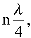
- With reference to any one of the first aspect to the third feasible implementation manner of the first aspect, in a fourth feasible implementation manner, the first antenna and the second antenna are located at a same side or different sides of a mainboard of a terminal.
- With reference to any one of the first aspect to the fourth feasible implementation manner of the first aspect, in a fifth feasible implementation manner, the first antenna or the second antenna includes any one of a monopole antenna and a loop antenna.
- A second aspect of the present invention provides a terminal, where the terminal may include an antenna system, and the antenna system includes a first antenna and a second antenna, where the first antenna and the second antenna are connected in parallel to an antenna feeding point, the antenna feeding point is connected to a radio frequency transceiver circuit of the terminal, and a phase-shift apparatus is connected in series between the first antenna or the second antenna and the antenna feeding point, so that an imaginary part of impedance at the antenna feeding point is canceled out near a central frequency channel number.
- With reference to the second aspect, in a first feasible implementation manner, the phase-shift apparatus is connected in series between the first antenna or the second antenna and the antenna feeding point, and input impedance Z1 of the first antenna and input impedance Z2 of the second antenna meet that: Z1=Z2; or Z1=A*Z2; or Z1=R1+JX1, Z2=R2+JX2, and R1*X2=R2*X1, where A is any real number.
- With reference to the first feasible implementation manner of the second aspect, in a second feasible implementation manner, the phase-shift apparatus includes: a transmission line, an inductor-capacitor LC oscillation circuit, or an integrated phase shifter.
- With reference to the second feasible implementation manner of the second aspect, in a third feasible implementation manner, when the phase-shift apparatus includes a transmission line, and when the transmission line is a single transmission line and is connected in series between the first antenna or the second antenna and the antenna feeding point, a length L of the transmission line is


- With reference to any one of the second aspect to the third feasible implementation manner of the second aspect, in a fourth feasible implementation manner, the first antenna and the second antenna are located at a same side or different sides of a mainboard of the terminal.
- With reference to any one of the second aspect to the fourth feasible implementation manner of the second aspect, in a fifth feasible implementation manner, the first antenna or the second antenna includes any one of a monopole antenna and a loop antenna.
- It can be seen from the above that, in some feasible implementation manners of the present invention, an antenna system is provided, where the antenna system includes a first antenna and a second antenna, where the first antenna and the second antenna are connected in parallel to an antenna feeding point, and a phase-shift apparatus is connected in series between the first antenna or the second antenna and the antenna feeding point, so that an imaginary part of impedance at the antenna feeding point is canceled out near a central frequency channel number. In this way, in embodiments of the present invention, radio frequency bandwidth of the antenna system in free space can be expanded, and average efficiency can be increased; in addition, compared with efficiency when only the first antenna or the second antenna is used, efficiency of the antenna system in the embodiments of the present invention is increased in scenarios of a head phantom, a hand phantom, and a head and hand phantom.
-
-
FIG. 1 is a schematic structural diagram of composition of an embodiment of an antenna system according to the present invention; -
FIG. 2 is a schematic structural diagram of composition of another embodiment of an antenna system according to the present invention; -
FIG. 3 is a schematic curve chart of a return loss according to the present invention; -
FIG. 4 is a schematic diagram of comparison, in scenarios of free space, a head phantom, a hand phantom, and a head and hand phantom, between efficiency of a first antenna before an antenna system of an embodiment of the present invention is used and efficiency of the first antenna after the antenna system of the embodiment of the present invention is used; and -
FIG. 5 is a schematic structural diagram of composition of an embodiment of a terminal according to the present invention. - The following uses specific embodiments to describe the present invention in detail.
-
FIG. 1 is a schematic structural diagram of composition of an embodiment of an antenna system according to the present invention. As shown inFIG. 1 , the antenna system may include: afirst antenna 11 and asecond antenna 21, where thefirst antenna 11 and thesecond antenna 21 are connected in parallel to anantenna feeding point 30, and a phase-shift apparatus 31 is connected in series between thefirst antenna 11 and theantenna feeding point 30, so that an imaginary part of impedance at theantenna feeding point 30 is canceled out near a central frequency channel number. It should be noted that, inFIG. 1 , the phase-shift apparatus 31 is connected in series between thefirst antenna 11 and theantenna feeding point 30, but in specific implementation, a location of the phase-shift apparatus 31 may be connected in series between thesecond antenna 21 and theantenna feeding point 30 instead. - As a feasible implementation manner, in this embodiment of the present invention shown in
FIG. 1 , input impedance Z1 of the first antenna and input impedance Z2 of the second antenna meet that: Z1=Z2; or Z1=A*Z2; or Z1=R1+JX1, Z2=R2+JX2, and R1*X2=R2*X1, where A is any real number. - As a feasible implementation manner, the phase-
shift apparatus 31 in this embodiment of the present invention may be a transmission line. As an implementation manner, a length L of the transmission line may be
- Certainly, alternatively, in specific implementation, the phase-
shift apparatus 31 in this embodiment of the present invention may be an inductor-capacitor LC circuit (which consists of an inductor and a capacitor), or a phase shifter formed by integrating the LC circuits. When the LC circuit or the phase shifter is used, in this embodiment of the present invention, an inductor and a capacitor that are of proper models may be selected to meet that an imaginary part of impedance at theantenna feeding point 30 is canceled out near a central frequency channel number (which refers to a central frequency channel number of an operating frequency band of an antenna, and may be also referred to as a resonance frequency channel number). - Generally, impedance of an antenna may be represented as Z=R+jX, where R is a real part of impedance Z, X is an imaginary part of Z, and in this embodiment of the present invention, that the imaginary part of the impedance of the antenna feeding point is canceled out means that at the central frequency channel number, impedance Z' of the antenna feeding point includes only the real part R.
- In specific implementation, the
first antenna 11 and thesecond antenna 21 in this embodiment of the present invention may be located at a same side or different sides of a mainboard of a terminal, where a specific location is not limited. For example, both thefirst antenna 11 and thesecond antenna 21 may be located at bottom of the terminal, or located on top of the terminal; or thefirst antenna 11 is located on top of the terminal, and thesecond antenna 21 is located at bottom of the terminal. - In specific implementation, the
first antenna 11 or thesecond antenna 21 in this embodiment of the present invention includes any one of a monopole antenna and a loop antenna. For example, both thefirst antenna 11 and thesecond antenna 21 are metal frame loop antennas, where an antenna size is 53 mm*10 mm*7.5 mm. -
FIG. 2 is a schematic structural diagram of composition of another embodiment of an antenna system according to the present invention. As shown inFIG. 2 , the antenna system may include: afirst antenna 11 and asecond antenna 21, where thefirst antenna 11 and thesecond antenna 21 are connected in parallel to anantenna feeding point 30, a first phase-shift apparatus 40 is connected in series between thefirst antenna 11 and theantenna feeding point 30, and a second phase-shift apparatus 50 is connected in series between thesecond antenna 21 and theantenna feeding point 30, so that an imaginary part of impedance at theantenna feeding point 30 is canceled out near a central frequency channel number. - As a feasible implementation manner, in this embodiment of the present invention shown in
FIG. 2 , input impedance Z1 of the first antenna and input impedance Z2 of the second antenna meet that: Z1=Z2; or Z1=A*Z2; or Z1=R1+JX1, Z2=R2+JX2, and R1*X2=R2*X1, where A is any real number. - As a feasible implementation manner, the phase-
shift apparatus 40 and the phase-shift apparatus 50 may be transmission lines. Assuming that a first transmission line is connected between the first antenna and the antenna feeding point, and a second transmission line is connected between the second antenna and the antenna feeding point, in this case, as an implementation manner, a length L1 of the first transmission line and a length L2 of the second transmission line may meet that:
- Certainly, alternatively, in specific implementation, in this embodiment of the present invention, the phase-
shift apparatus 40 and the phase-shift apparatus 50 may be inductor-capacitor LC circuits (where an inductor-capacitor LC circuit consists of an inductor and a capacitor), or phase shifters formed by integrating the LC circuits. When the LC circuits or the phase shifters are used, in this embodiment of the present invention, an inductor and a capacitor that are of proper models may be selected to meet that an imaginary part of impedance at theantenna feeding point 30 is canceled out near a central frequency channel number (which refers to a central frequency channel number of an operating frequency band of an antenna, and may be also referred to as a resonance frequency channel number). - In specific implementation, the
first antenna 11 and thesecond antenna 21 in this embodiment of the present invention may be located at a same side or different sides of a mainboard of a terminal, where a specific location is not limited. For example, both thefirst antenna 11 and thesecond antenna 21 may be located at bottom of the terminal, or located on top of the terminal; or thefirst antenna 11 is located on top of the terminal, and thesecond antenna 21 is located at bottom of the terminal. - In specific implementation, the
first antenna 11 or thesecond antenna 21 in this embodiment of the present invention includes any one of a monopole antenna and a loop antenna. For example, both thefirst antenna 11 and thesecond antenna 21 are metal frame loop antennas, where an antenna size is 53 mm*10 mm*7.5 mm. - Further, to present an effect of this embodiment of the present invention, it is assumed that impedance of the
first antenna 11 becomes Z1' after a phase of the impedance is shifted by the transmission line with a length of L1, and impedance of thesecond antenna 21 becomes Z2' after a phase of the impedance is shifted by the transmission line with a length of L2, impedance of the antenna feeding point is Z3, Z3= Z2'//Z1' (that is, Z3 is parallel impedance of Z1' and Z2'). Referring toFIG. 3 , a return loss curve of Z1' is a curve represented by a dotted line, a return loss curve of Z2' is a curve represented by a dashed line, and a return loss curve of Z3 is a curve represented by a solid line. It can be learned fromFIG. 3 that, compared with those of Z1' and Z2', when a return loss of Z3 is -3dB, bandwidth increases by more than one time and there is an obvious bandwidth expanding effect. - Further,
FIG. 4 is a schematic diagram of comparison, in scenarios of free space, a head phantom, a hand phantom, and a head and hand phantom, between efficiency of the first antenna before the antenna system of this embodiment of the present invention is used and efficiency of the first antenna after the antenna system of this embodiment of the present invention is used. It can be learned fromFIG. 4 that: - In the free space scenario, after the
first antenna 11 is connected in parallel to thesecond antenna 21 by the using phase-shift apparatus, low frequency bandwidth of the entire antenna system is expanded by about 200Mhz (where an efficiency limit is -4dB), and high frequency bandwidth is expanded by about 100Mhz. After optimization, an entire LTE frequency band (704Mhz-960Mhz, 1710-2690Mhz) can be easily covered, and average efficiency of the entire antenna system in all bandwidths is increased to some extent. - In the hand phantom scenario, the
first antenna 11 is increased by 7dB in a low frequency hand phantom, and is increased by 3dB in a high frequency hand phantom; and in the head and hand phantom scenario, a head and hand phantom low frequency of thefirst antenna 11 is increased by 5dB, and a high frequency is increased by 1dB. - In addition, when the antenna system in this embodiment of the present invention is not used, in the head and hand phantom scenario, low frequency of the
first antenna 11 has a relatively large frequency deviation, and deviates toward low frequency for about 300Mhz, which is a great difficulty in actual design of how to balance free space performance, hand phantom performance, and head and hand phantom performance. However, after the antenna system of the present invention is used, there is no obvious frequency deviation in the hand phantom and the head and hand phantom of the entire antenna system, which can effectively solve this problem. - Correspondingly, an embodiment of the present invention further provides a terminal. As shown in
FIG. 5 , the terminal may include anantenna system 1 and a radiofrequency transceiver circuit 2 that are mentioned above in the present invention, where the radiofrequency transceiver circuit 2 is connected to anantenna feeding point 30 of theantenna system 1. Theantenna system 1 includes: afirst antenna 11 and asecond antenna 21, where thefirst antenna 11 and thesecond antenna 21 are connected in parallel to theantenna feeding point 30, and further, a first phase-shift apparatus 40 is connected in series between thefirst antenna 11 and theantenna feeding point 30, and a second phase-shift apparatus 50 is connected in series between thesecond antenna 21 and theantenna feeding point 30, so that an imaginary part of impedance at theantenna feeding point 30 is canceled out near a central frequency channel number. - In
FIG. 5 , only an instance of theantenna system 1 is illustrated. In specific implementation, theantenna system 1 inFIG. 5 of the present invention may include a first antenna and a second antenna, where the first antenna and the second antenna are connected in parallel to an antenna feeding point, and a phase-shift apparatus is connected in series between the first antenna or the second antenna and the antenna feeding point, so that an imaginary part of impedance at the antenna feeding point is canceled out near a central frequency channel number. Besides what is shown inFIG. 1 and FIG. 2 , there may further be other specific embodiments of the antenna system that are not illustrated, and the instance shown inFIG. 5 cannot be used to limit the antenna system. - In summary, what is described above is merely exemplary embodiments of the technical solutions of the present invention, but is not intended to limit the protection scope of the present invention. Any modification, equivalent replacement, or improvement made without departing from the principle of the present invention shall fall within the protection scope of the present invention.
Claims (10)
- An antenna system, comprising a first antenna and a second antenna, wherein the first antenna and the second antenna are connected in parallel to an antenna feeding point, and a phase-shift apparatus is connected in series between the first antenna or the second antenna and the antenna feeding point, so that an imaginary part of impedance at the antenna feeding point is canceled out near a central frequency channel number.
- The antenna system according to claim 1, wherein the phase-shift apparatus is connected in series between the first antenna or the second antenna and the antenna feeding point, and input impedance Z1 of the first antenna and input impedance Z2 of the second antenna meet that: Z1=Z2; or Z1=A*Z2; or Z1=R1+JX1, Z2=R2+JX2, and R1*X2=R2*X1, wherein A is any real number.
- The antenna system according to claim 2, wherein the phase-shift apparatus comprises: a transmission line, an inductor-capacitor LC oscillation circuit, or an integrated phase shifter.
- The antenna system according to claim 3, wherein when the phase-shift apparatus comprises a single transmission line, the transmission line is connected in series between the first antenna or the second antenna and the antenna feeding point, and a length L of the transmission line is


- The antenna system according to any one of claims 1 to 4, wherein the first antenna or the second antenna comprises any one of a monopole antenna and a loop antenna.
- A terminal, comprising an antenna system, wherein the antenna system comprises a first antenna and a second antenna, wherein the first antenna and the second antenna are connected in parallel to an antenna feeding point, the antenna feeding point is connected to a radio frequency transceiver circuit of the terminal, and a phase-shift apparatus is connected in series between the first antenna or the second antenna and the antenna feeding point, so that an imaginary part of impedance at the antenna feeding point is canceled out near a central frequency channel number.
- The terminal according to claim 6, wherein the phase-shift apparatus is connected in series between the first antenna or the second antenna and the antenna feeding point, and input impedance Z1 of the first antenna and input impedance Z2 of the second antenna meet that: Z1=Z2; or Z1=A*Z2; or Z1=R1+JX1, Z2=R2+JX2, and R1*X2=R2*X1, wherein A is any real number.
- The terminal according to claim 7, wherein the phase-shift apparatus comprises: a transmission line, an inductor-capacitor LC oscillation circuit, or an integrated phase shifter.
- The terminal according to claim 8, wherein when the phase-shift apparatus comprises a single transmission line, the transmission line is connected in series between the first antenna or the second antenna and the antenna feeding point, and a length L of the transmission line is


- The terminal according to any one of claims 6 to 9, wherein the first antenna or the second antenna comprises any one of a monopole antenna and a loop antenna.
Applications Claiming Priority (1)
| Application Number | Priority Date | Filing Date | Title |
|---|---|---|---|
| PCT/CN2014/075941 WO2015161444A1 (en) | 2014-04-22 | 2014-04-22 | Antenna system and terminal |
Publications (3)
| Publication Number | Publication Date |
|---|---|
| EP2999049A1 true EP2999049A1 (en) | 2016-03-23 |
| EP2999049A4 EP2999049A4 (en) | 2016-07-27 |
| EP2999049B1 EP2999049B1 (en) | 2020-05-20 |
Family
ID=52408644
Family Applications (1)
| Application Number | Title | Priority Date | Filing Date |
|---|---|---|---|
| EP14889900.8A Active EP2999049B1 (en) | 2014-04-22 | 2014-04-22 | Antenna system and terminal |
Country Status (6)
| Country | Link |
|---|---|
| US (1) | US9905934B2 (en) |
| EP (1) | EP2999049B1 (en) |
| JP (1) | JP2016527802A (en) |
| KR (1) | KR20160015387A (en) |
| CN (1) | CN104335420A (en) |
| WO (1) | WO2015161444A1 (en) |
Cited By (1)
| Publication number | Priority date | Publication date | Assignee | Title |
|---|---|---|---|---|
| WO2018048044A2 (en) | 2016-09-07 | 2018-03-15 | Lg Electronics Inc. | Mobile terminal |
Families Citing this family (6)
| Publication number | Priority date | Publication date | Assignee | Title |
|---|---|---|---|---|
| CN105337041A (en) * | 2015-09-29 | 2016-02-17 | 大连海事大学 | Full-band television transmitting antenna based on rhombic oscillators |
| US10333222B2 (en) * | 2016-04-11 | 2019-06-25 | Electronics And Telecommunications Research Institute | Method of improving bandwidth of antenna using transmission line stub |
| CN108539416B (en) * | 2018-01-29 | 2021-01-15 | 上海安费诺永亿通讯电子有限公司 | Same-frequency dual-antenna system, decoupling method, antenna equipment and mobile terminal |
| KR102597392B1 (en) * | 2019-02-28 | 2023-11-03 | 삼성전자주식회사 | Antenna module supporting dual bands and electronic device including the same |
| CN109888492B (en) * | 2019-03-11 | 2020-03-27 | 南京理工大学 | A sunken phase-shifting power divider |
| CN117477208A (en) * | 2023-11-09 | 2024-01-30 | 西安交通大学 | Methods to expand the antenna bandwidth of mobile terminal equipment |
Family Cites Families (21)
| Publication number | Priority date | Publication date | Assignee | Title |
|---|---|---|---|---|
| DE69417106T2 (en) * | 1993-07-01 | 1999-07-01 | The Commonwealth Scientific And Industrial Research Organization, Campbell | Plane antenna |
| JP2001267841A (en) * | 2000-03-23 | 2001-09-28 | Sony Corp | Antenna device and portable radio |
| US6337670B1 (en) * | 2000-09-27 | 2002-01-08 | Auden Technology Corp. Mfg. Co., Ltd. | Omni-directional broadband helical antenna array |
| JP2002141732A (en) * | 2000-11-02 | 2002-05-17 | Hiroyuki Arai | Two-element meandering line sleeve antenna |
| KR100446506B1 (en) * | 2000-11-13 | 2004-09-04 | 삼성전자주식회사 | Portable terminal equipment |
| US7184727B2 (en) * | 2002-02-12 | 2007-02-27 | Kyocera Wireless Corp. | Full-duplex antenna system and method |
| TW200408163A (en) * | 2002-11-07 | 2004-05-16 | High Tech Comp Corp | Improved cellular antenna architecture |
| US20070146210A1 (en) | 2004-02-25 | 2007-06-28 | Koninklijke Philips Electronic, N.V. | Antenna array |
| WO2007141187A2 (en) * | 2006-06-08 | 2007-12-13 | Fractus, S.A. | Distributed antenna system robust to human body loading effects |
| US7724194B2 (en) * | 2006-06-30 | 2010-05-25 | Motorola, Inc. | Dual autodiplexing antenna |
| PL2092641T3 (en) * | 2006-11-17 | 2017-08-31 | Nokia Technologies Oy | An apparatus for enabling two elements to share a common feed |
| US7683844B2 (en) * | 2007-05-16 | 2010-03-23 | Intel Corporation | Mm-wave scanning antenna |
| JP5380997B2 (en) | 2008-10-15 | 2014-01-08 | パナソニック株式会社 | Diversity antenna device and electronic device using the same |
| TW201042822A (en) * | 2009-05-25 | 2010-12-01 | Mitac Int Corp | Antenna array |
| WO2011068060A1 (en) * | 2009-12-01 | 2011-06-09 | 株式会社村田製作所 | Antenna matching device, antenna device, and mobile communication terminal |
| EP2472673B1 (en) | 2010-01-05 | 2016-05-04 | Sony Corporation | Antenna device and communications device |
| US9231730B2 (en) | 2010-09-30 | 2016-01-05 | Panasonic Intellectual Property Management Co., Ltd. | Radio communication device |
| CN102544761A (en) * | 2010-12-22 | 2012-07-04 | 和硕联合科技股份有限公司 | Electronic device |
| CN102299414A (en) * | 2011-06-03 | 2011-12-28 | 上海安费诺永亿通讯电子有限公司 | Adjustable CMMB built-in terminal antenna |
| US9577325B2 (en) * | 2012-06-20 | 2017-02-21 | Fractus Antennas, S.L. | Compact radiating array for wireless handheld or portable devices |
| CN203456585U (en) * | 2013-09-23 | 2014-02-26 | 深圳光启创新技术有限公司 | A wireless communication apparatus, a communication antenna thereof, and a communication antenna assembly |
-
2014
- 2014-04-22 EP EP14889900.8A patent/EP2999049B1/en active Active
- 2014-04-22 KR KR1020167000358A patent/KR20160015387A/en not_active Ceased
- 2014-04-22 WO PCT/CN2014/075941 patent/WO2015161444A1/en not_active Ceased
- 2014-04-22 JP JP2016528307A patent/JP2016527802A/en active Pending
- 2014-04-22 CN CN201480001236.5A patent/CN104335420A/en active Pending
-
2015
- 2015-12-17 US US14/973,016 patent/US9905934B2/en active Active
Cited By (3)
| Publication number | Priority date | Publication date | Assignee | Title |
|---|---|---|---|---|
| WO2018048044A2 (en) | 2016-09-07 | 2018-03-15 | Lg Electronics Inc. | Mobile terminal |
| EP3510667A4 (en) * | 2016-09-07 | 2020-04-01 | LG Electronics Inc. -1- | MOBILE TERMINAL |
| US10840582B2 (en) | 2016-09-07 | 2020-11-17 | Lg Electronics Inc. | Mobile terminal |
Also Published As
| Publication number | Publication date |
|---|---|
| EP2999049A4 (en) | 2016-07-27 |
| US20160104945A1 (en) | 2016-04-14 |
| CN104335420A (en) | 2015-02-04 |
| WO2015161444A1 (en) | 2015-10-29 |
| US9905934B2 (en) | 2018-02-27 |
| KR20160015387A (en) | 2016-02-12 |
| JP2016527802A (en) | 2016-09-08 |
| EP2999049B1 (en) | 2020-05-20 |
Similar Documents
| Publication | Publication Date | Title |
|---|---|---|
| US9905934B2 (en) | Antenna system and terminal | |
| US10734720B2 (en) | Antenna and communications device | |
| EP3082192A1 (en) | Antenna and mobile terminal | |
| EP3130034B1 (en) | Capacitively-coupled isolator assembly | |
| US9300041B2 (en) | Multimode broadband antenna module and wireless terminal | |
| EP2942834A1 (en) | Antenna apparatus and terminal device | |
| US9614571B2 (en) | Multi-band isolator assembly | |
| US10847888B2 (en) | Planar end fire antenna for wideband low form factor applications | |
| CN108428995A (en) | Electronic equipment | |
| US20160233576A1 (en) | Multi-frequency antenna and terminal | |
| EP3200280A1 (en) | Wireless mobile device | |
| EP3739762A1 (en) | Terminal device | |
| CN103633419A (en) | Mobile device | |
| TWI492606B (en) | Mobile apparatus with radio frequency architecture supporting simultaneous data and voice communications | |
| CN105978600A (en) | Processor and mobile terminal for supporting carrier aggregation | |
| US20150102978A1 (en) | Printed Antenna and Terminal Device | |
| CN203933967U (en) | A kind of antenna structure and mobile terminal | |
| CN105227198B (en) | A kind of antenna system and mobile terminal | |
| CN201975511U (en) | Terminal antenna | |
| CN104332696A (en) | MIMO antenna structure of mobile phone | |
| AU2018435028B2 (en) | Tunable antenna and communications terminal | |
| CN203775416U (en) | Base station | |
| CN105449359A (en) | Antenna system, mobile terminal and communication method | |
| EP4576598A1 (en) | Communication device and base station |
Legal Events
| Date | Code | Title | Description |
|---|---|---|---|
| PUAI | Public reference made under article 153(3) epc to a published international application that has entered the european phase |
Free format text: ORIGINAL CODE: 0009012 |
|
| 17P | Request for examination filed |
Effective date: 20151216 |
|
| AK | Designated contracting states |
Kind code of ref document: A1 Designated state(s): AL AT BE BG CH CY CZ DE DK EE ES FI FR GB GR HR HU IE IS IT LI LT LU LV MC MK MT NL NO PL PT RO RS SE SI SK SM TR |
|
| AX | Request for extension of the european patent |
Extension state: BA ME |
|
| A4 | Supplementary search report drawn up and despatched |
Effective date: 20160624 |
|
| RIC1 | Information provided on ipc code assigned before grant |
Ipc: H01Q 1/24 20060101ALI20160620BHEP Ipc: H04B 1/18 20060101ALI20160620BHEP Ipc: H01Q 21/00 20060101AFI20160620BHEP Ipc: H01Q 21/30 20060101ALI20160620BHEP Ipc: H01Q 5/321 20150101ALI20160620BHEP Ipc: H01Q 21/28 20060101ALI20160620BHEP |
|
| DAX | Request for extension of the european patent (deleted) | ||
| RAP1 | Party data changed (applicant data changed or rights of an application transferred) |
Owner name: HUAWEI DEVICE (DONGGUAN) CO., LTD. |
|
| STAA | Information on the status of an ep patent application or granted ep patent |
Free format text: STATUS: EXAMINATION IS IN PROGRESS |
|
| 17Q | First examination report despatched |
Effective date: 20181121 |
|
| RAP1 | Party data changed (applicant data changed or rights of an application transferred) |
Owner name: HUAWEI DEVICE CO., LTD. |
|
| REG | Reference to a national code |
Ref country code: DE Ref legal event code: R079 Ref document number: 602014065783 Country of ref document: DE Free format text: PREVIOUS MAIN CLASS: H01Q0021000000 Ipc: H01Q0021300000 |
|
| GRAP | Despatch of communication of intention to grant a patent |
Free format text: ORIGINAL CODE: EPIDOSNIGR1 |
|
| STAA | Information on the status of an ep patent application or granted ep patent |
Free format text: STATUS: GRANT OF PATENT IS INTENDED |
|
| RIC1 | Information provided on ipc code assigned before grant |
Ipc: H01Q 5/321 20150101ALI20191113BHEP Ipc: H01Q 21/28 20060101ALI20191113BHEP Ipc: H04B 1/18 20060101ALI20191113BHEP Ipc: H01Q 1/24 20060101ALI20191113BHEP Ipc: H01Q 21/30 20060101AFI20191113BHEP |
|
| INTG | Intention to grant announced |
Effective date: 20191202 |
|
| GRAS | Grant fee paid |
Free format text: ORIGINAL CODE: EPIDOSNIGR3 |
|
| GRAA | (expected) grant |
Free format text: ORIGINAL CODE: 0009210 |
|
| STAA | Information on the status of an ep patent application or granted ep patent |
Free format text: STATUS: THE PATENT HAS BEEN GRANTED |
|
| AK | Designated contracting states |
Kind code of ref document: B1 Designated state(s): AL AT BE BG CH CY CZ DE DK EE ES FI FR GB GR HR HU IE IS IT LI LT LU LV MC MK MT NL NO PL PT RO RS SE SI SK SM TR |
|
| REG | Reference to a national code |
Ref country code: GB Ref legal event code: FG4D |
|
| REG | Reference to a national code |
Ref country code: CH Ref legal event code: EP |
|
| REG | Reference to a national code |
Ref country code: DE Ref legal event code: R096 Ref document number: 602014065783 Country of ref document: DE |
|
| REG | Reference to a national code |
Ref country code: AT Ref legal event code: REF Ref document number: 1273231 Country of ref document: AT Kind code of ref document: T Effective date: 20200615 |
|
| REG | Reference to a national code |
Ref country code: LT Ref legal event code: MG4D |
|
| REG | Reference to a national code |
Ref country code: NL Ref legal event code: MP Effective date: 20200520 |
|
| PG25 | Lapsed in a contracting state [announced via postgrant information from national office to epo] |
Ref country code: IS Free format text: LAPSE BECAUSE OF FAILURE TO SUBMIT A TRANSLATION OF THE DESCRIPTION OR TO PAY THE FEE WITHIN THE PRESCRIBED TIME-LIMIT Effective date: 20200920 Ref country code: FI Free format text: LAPSE BECAUSE OF FAILURE TO SUBMIT A TRANSLATION OF THE DESCRIPTION OR TO PAY THE FEE WITHIN THE PRESCRIBED TIME-LIMIT Effective date: 20200520 Ref country code: PT Free format text: LAPSE BECAUSE OF FAILURE TO SUBMIT A TRANSLATION OF THE DESCRIPTION OR TO PAY THE FEE WITHIN THE PRESCRIBED TIME-LIMIT Effective date: 20200921 Ref country code: LT Free format text: LAPSE BECAUSE OF FAILURE TO SUBMIT A TRANSLATION OF THE DESCRIPTION OR TO PAY THE FEE WITHIN THE PRESCRIBED TIME-LIMIT Effective date: 20200520 Ref country code: SE Free format text: LAPSE BECAUSE OF FAILURE TO SUBMIT A TRANSLATION OF THE DESCRIPTION OR TO PAY THE FEE WITHIN THE PRESCRIBED TIME-LIMIT Effective date: 20200520 Ref country code: NO Free format text: LAPSE BECAUSE OF FAILURE TO SUBMIT A TRANSLATION OF THE DESCRIPTION OR TO PAY THE FEE WITHIN THE PRESCRIBED TIME-LIMIT Effective date: 20200820 Ref country code: GR Free format text: LAPSE BECAUSE OF FAILURE TO SUBMIT A TRANSLATION OF THE DESCRIPTION OR TO PAY THE FEE WITHIN THE PRESCRIBED TIME-LIMIT Effective date: 20200821 |
|
| PG25 | Lapsed in a contracting state [announced via postgrant information from national office to epo] |
Ref country code: RS Free format text: LAPSE BECAUSE OF FAILURE TO SUBMIT A TRANSLATION OF THE DESCRIPTION OR TO PAY THE FEE WITHIN THE PRESCRIBED TIME-LIMIT Effective date: 20200520 Ref country code: BG Free format text: LAPSE BECAUSE OF FAILURE TO SUBMIT A TRANSLATION OF THE DESCRIPTION OR TO PAY THE FEE WITHIN THE PRESCRIBED TIME-LIMIT Effective date: 20200820 Ref country code: LV Free format text: LAPSE BECAUSE OF FAILURE TO SUBMIT A TRANSLATION OF THE DESCRIPTION OR TO PAY THE FEE WITHIN THE PRESCRIBED TIME-LIMIT Effective date: 20200520 Ref country code: HR Free format text: LAPSE BECAUSE OF FAILURE TO SUBMIT A TRANSLATION OF THE DESCRIPTION OR TO PAY THE FEE WITHIN THE PRESCRIBED TIME-LIMIT Effective date: 20200520 |
|
| REG | Reference to a national code |
Ref country code: AT Ref legal event code: MK05 Ref document number: 1273231 Country of ref document: AT Kind code of ref document: T Effective date: 20200520 |
|
| PG25 | Lapsed in a contracting state [announced via postgrant information from national office to epo] |
Ref country code: AL Free format text: LAPSE BECAUSE OF FAILURE TO SUBMIT A TRANSLATION OF THE DESCRIPTION OR TO PAY THE FEE WITHIN THE PRESCRIBED TIME-LIMIT Effective date: 20200520 Ref country code: NL Free format text: LAPSE BECAUSE OF FAILURE TO SUBMIT A TRANSLATION OF THE DESCRIPTION OR TO PAY THE FEE WITHIN THE PRESCRIBED TIME-LIMIT Effective date: 20200520 |
|
| PG25 | Lapsed in a contracting state [announced via postgrant information from national office to epo] |
Ref country code: DK Free format text: LAPSE BECAUSE OF FAILURE TO SUBMIT A TRANSLATION OF THE DESCRIPTION OR TO PAY THE FEE WITHIN THE PRESCRIBED TIME-LIMIT Effective date: 20200520 Ref country code: SM Free format text: LAPSE BECAUSE OF FAILURE TO SUBMIT A TRANSLATION OF THE DESCRIPTION OR TO PAY THE FEE WITHIN THE PRESCRIBED TIME-LIMIT Effective date: 20200520 Ref country code: EE Free format text: LAPSE BECAUSE OF FAILURE TO SUBMIT A TRANSLATION OF THE DESCRIPTION OR TO PAY THE FEE WITHIN THE PRESCRIBED TIME-LIMIT Effective date: 20200520 Ref country code: AT Free format text: LAPSE BECAUSE OF FAILURE TO SUBMIT A TRANSLATION OF THE DESCRIPTION OR TO PAY THE FEE WITHIN THE PRESCRIBED TIME-LIMIT Effective date: 20200520 Ref country code: IT Free format text: LAPSE BECAUSE OF FAILURE TO SUBMIT A TRANSLATION OF THE DESCRIPTION OR TO PAY THE FEE WITHIN THE PRESCRIBED TIME-LIMIT Effective date: 20200520 Ref country code: CZ Free format text: LAPSE BECAUSE OF FAILURE TO SUBMIT A TRANSLATION OF THE DESCRIPTION OR TO PAY THE FEE WITHIN THE PRESCRIBED TIME-LIMIT Effective date: 20200520 Ref country code: RO Free format text: LAPSE BECAUSE OF FAILURE TO SUBMIT A TRANSLATION OF THE DESCRIPTION OR TO PAY THE FEE WITHIN THE PRESCRIBED TIME-LIMIT Effective date: 20200520 Ref country code: ES Free format text: LAPSE BECAUSE OF FAILURE TO SUBMIT A TRANSLATION OF THE DESCRIPTION OR TO PAY THE FEE WITHIN THE PRESCRIBED TIME-LIMIT Effective date: 20200520 |
|
| REG | Reference to a national code |
Ref country code: DE Ref legal event code: R097 Ref document number: 602014065783 Country of ref document: DE |
|
| PG25 | Lapsed in a contracting state [announced via postgrant information from national office to epo] |
Ref country code: PL Free format text: LAPSE BECAUSE OF FAILURE TO SUBMIT A TRANSLATION OF THE DESCRIPTION OR TO PAY THE FEE WITHIN THE PRESCRIBED TIME-LIMIT Effective date: 20200520 Ref country code: SK Free format text: LAPSE BECAUSE OF FAILURE TO SUBMIT A TRANSLATION OF THE DESCRIPTION OR TO PAY THE FEE WITHIN THE PRESCRIBED TIME-LIMIT Effective date: 20200520 |
|
| PLBE | No opposition filed within time limit |
Free format text: ORIGINAL CODE: 0009261 |
|
| STAA | Information on the status of an ep patent application or granted ep patent |
Free format text: STATUS: NO OPPOSITION FILED WITHIN TIME LIMIT |
|
| 26N | No opposition filed |
Effective date: 20210223 |
|
| PG25 | Lapsed in a contracting state [announced via postgrant information from national office to epo] |
Ref country code: SI Free format text: LAPSE BECAUSE OF FAILURE TO SUBMIT A TRANSLATION OF THE DESCRIPTION OR TO PAY THE FEE WITHIN THE PRESCRIBED TIME-LIMIT Effective date: 20200520 |
|
| PG25 | Lapsed in a contracting state [announced via postgrant information from national office to epo] |
Ref country code: MC Free format text: LAPSE BECAUSE OF FAILURE TO SUBMIT A TRANSLATION OF THE DESCRIPTION OR TO PAY THE FEE WITHIN THE PRESCRIBED TIME-LIMIT Effective date: 20200520 |
|
| PG25 | Lapsed in a contracting state [announced via postgrant information from national office to epo] |
Ref country code: LU Free format text: LAPSE BECAUSE OF NON-PAYMENT OF DUE FEES Effective date: 20210422 |
|
| REG | Reference to a national code |
Ref country code: BE Ref legal event code: MM Effective date: 20210430 |
|
| PG25 | Lapsed in a contracting state [announced via postgrant information from national office to epo] |
Ref country code: LI Free format text: LAPSE BECAUSE OF NON-PAYMENT OF DUE FEES Effective date: 20210430 Ref country code: CH Free format text: LAPSE BECAUSE OF NON-PAYMENT OF DUE FEES Effective date: 20210430 |
|
| PG25 | Lapsed in a contracting state [announced via postgrant information from national office to epo] |
Ref country code: IE Free format text: LAPSE BECAUSE OF NON-PAYMENT OF DUE FEES Effective date: 20210422 |
|
| PG25 | Lapsed in a contracting state [announced via postgrant information from national office to epo] |
Ref country code: BE Free format text: LAPSE BECAUSE OF NON-PAYMENT OF DUE FEES Effective date: 20210430 |
|
| PG25 | Lapsed in a contracting state [announced via postgrant information from national office to epo] |
Ref country code: HU Free format text: LAPSE BECAUSE OF FAILURE TO SUBMIT A TRANSLATION OF THE DESCRIPTION OR TO PAY THE FEE WITHIN THE PRESCRIBED TIME-LIMIT; INVALID AB INITIO Effective date: 20140422 |
|
| PG25 | Lapsed in a contracting state [announced via postgrant information from national office to epo] |
Ref country code: CY Free format text: LAPSE BECAUSE OF FAILURE TO SUBMIT A TRANSLATION OF THE DESCRIPTION OR TO PAY THE FEE WITHIN THE PRESCRIBED TIME-LIMIT Effective date: 20200520 |
|
| PG25 | Lapsed in a contracting state [announced via postgrant information from national office to epo] |
Ref country code: MK Free format text: LAPSE BECAUSE OF FAILURE TO SUBMIT A TRANSLATION OF THE DESCRIPTION OR TO PAY THE FEE WITHIN THE PRESCRIBED TIME-LIMIT Effective date: 20200520 |
|
| PG25 | Lapsed in a contracting state [announced via postgrant information from national office to epo] |
Ref country code: TR Free format text: LAPSE BECAUSE OF FAILURE TO SUBMIT A TRANSLATION OF THE DESCRIPTION OR TO PAY THE FEE WITHIN THE PRESCRIBED TIME-LIMIT Effective date: 20200520 |
|
| PG25 | Lapsed in a contracting state [announced via postgrant information from national office to epo] |
Ref country code: MT Free format text: LAPSE BECAUSE OF FAILURE TO SUBMIT A TRANSLATION OF THE DESCRIPTION OR TO PAY THE FEE WITHIN THE PRESCRIBED TIME-LIMIT Effective date: 20200520 |
|
| PGFP | Annual fee paid to national office [announced via postgrant information from national office to epo] |
Ref country code: FR Payment date: 20250310 Year of fee payment: 12 |
|
| PGFP | Annual fee paid to national office [announced via postgrant information from national office to epo] |
Ref country code: GB Payment date: 20250306 Year of fee payment: 12 |
|
| PGFP | Annual fee paid to national office [announced via postgrant information from national office to epo] |
Ref country code: DE Payment date: 20250305 Year of fee payment: 12 |