EP2998936A2 - Method for generating a combined projection image - Google Patents
Method for generating a combined projection image Download PDFInfo
- Publication number
- EP2998936A2 EP2998936A2 EP15180132.1A EP15180132A EP2998936A2 EP 2998936 A2 EP2998936 A2 EP 2998936A2 EP 15180132 A EP15180132 A EP 15180132A EP 2998936 A2 EP2998936 A2 EP 2998936A2
- Authority
- EP
- European Patent Office
- Prior art keywords
- projection
- projection image
- images
- initial
- generating
- Prior art date
- Legal status (The legal status is an assumption and is not a legal conclusion. Google has not performed a legal analysis and makes no representation as to the accuracy of the status listed.)
- Granted
Links
Images



Classifications
-
- G—PHYSICS
- G06—COMPUTING OR CALCULATING; COUNTING
- G06T—IMAGE DATA PROCESSING OR GENERATION, IN GENERAL
- G06T12/00—Tomographic reconstruction from projections
- G06T12/30—Image post-processing, e.g. metal artefact correction
-
- A—HUMAN NECESSITIES
- A61—MEDICAL OR VETERINARY SCIENCE; HYGIENE
- A61B—DIAGNOSIS; SURGERY; IDENTIFICATION
- A61B6/00—Apparatus or devices for radiation diagnosis; Apparatus or devices for radiation diagnosis combined with radiation therapy equipment
- A61B6/02—Arrangements for diagnosis sequentially in different planes; Stereoscopic radiation diagnosis
- A61B6/03—Computed tomography [CT]
- A61B6/032—Transmission computed tomography [CT]
-
- A—HUMAN NECESSITIES
- A61—MEDICAL OR VETERINARY SCIENCE; HYGIENE
- A61B—DIAGNOSIS; SURGERY; IDENTIFICATION
- A61B6/00—Apparatus or devices for radiation diagnosis; Apparatus or devices for radiation diagnosis combined with radiation therapy equipment
- A61B6/40—Arrangements for generating radiation specially adapted for radiation diagnosis
- A61B6/4064—Arrangements for generating radiation specially adapted for radiation diagnosis specially adapted for producing a particular type of beam
- A61B6/4078—Fan-beams
-
- A—HUMAN NECESSITIES
- A61—MEDICAL OR VETERINARY SCIENCE; HYGIENE
- A61B—DIAGNOSIS; SURGERY; IDENTIFICATION
- A61B6/00—Apparatus or devices for radiation diagnosis; Apparatus or devices for radiation diagnosis combined with radiation therapy equipment
- A61B6/52—Devices using data or image processing specially adapted for radiation diagnosis
- A61B6/5205—Devices using data or image processing specially adapted for radiation diagnosis involving processing of raw data to produce diagnostic data
-
- G—PHYSICS
- G06—COMPUTING OR CALCULATING; COUNTING
- G06T—IMAGE DATA PROCESSING OR GENERATION, IN GENERAL
- G06T12/00—Tomographic reconstruction from projections
-
- G—PHYSICS
- G06—COMPUTING OR CALCULATING; COUNTING
- G06T—IMAGE DATA PROCESSING OR GENERATION, IN GENERAL
- G06T2211/00—Image generation
- G06T2211/40—Computed tomography
- G06T2211/436—Limited angle
Definitions
- the present invention relates to a method for generating a combined projection image (SM) from a medical inspection object and an imaging device for generating a combined projection image (SM) from a medical inspection object.
- Computed tomography usually X-ray computed tomography
- X-ray computed tomography is a widely-used medical diagnostic tool, which allows the generation of tomographic images or slices of an area of interest in a patient.
- Radiologists often prefer using thick slab or thick-slice volume for diagnostic and screening reading.
- 5.0 mm slabs are often used for clinical reading and data storage in thoracic CT, although thin, high resolution 0.5 mm slabs are available and used for computer applications such as three-dimensional volume rendering and computer aided diagnosis algorithms.
- the slab thickness is related to the combined thickness of the original slices in the volume.
- a slab is rendered as a two-dimensional image, so that the image can be printed or viewed on a computer screen.
- DBT Digital Breast Tomosynthesis
- data volumes are often reconstructed at a higher resolution, for example at a resolution of 85 microns for a slice thickness of 1.0 mm.
- Such a high-resolution volume allows visualization of the fine clinical details required for accurate medical diagnosis of breast cancer, for example microcalcifications of only 100 microns in size, very fine spiculations of masses, etc.
- a correct depiction of microcalcification morphology and spiculations is critical for the radiologist in order to be able to differentiate between benign and malignant lesions in breast tissue.
- the amount of data in DBT volumes is very large. For example, the total volume of data for a single patient (e.g. including two DBT views and projection images) can exceed one gigabyte. The large data volume complicates data transfer and increases radiologist workload.
- a lesion In breast tissue, a lesion can often extend over 10.0 mm or more, and can extend in any random direction. Therefore, in order to be able to perform such an evaluation, a radiologist should be provided with very thick slabs, i.e. slabs with a thickness in excess of 10.0 mm. In some cases, it might be desirable to perform such an evaluation over the total volume (essentially the whole volume collapsed into a single slab). In the context of DBT such a single slab has also been called synthetic mammogram (SM) due to its similarity to conventional 2D mammograms.
- SM synthetic mammogram
- this object is solved by a method for generating a combined projection image from a medical inspection object, comprising the steps of capturing a set of initial projection images; reconstructing a first and a second three-dimensional volume from the set of initial projection images; generating a first re-projection image from the first three-dimensional volume and a second re-projection image from the second three-dimensional volume; weighting the first re-projection image and the second re-projection image; and combining the weighted first re-projection image and second re-projection image for generating the combined projection image.
- the quality of the combined projection image is improved and noise is reduced. Diagnostically relevant information can be highlighted while image information with less relevance is down-weighed.
- the first and/or second re-projection image is generated under an orthographic projection geometry, cone beam projection geometry or fan beam projection geometry from the first and/or second three-dimensional volume.
- geometries are employed that increase sharpness of the combined projection image.
- the first re-projection image and second re-projection image are linearly combined for generating the combined projection image.
- the combined projection image can be generated with few computational steps.
- reconstructing the first and second three-dimensional volume is based on a filtered back-projection algorithm.
- the three-dimensional volumes can be generated efficiently.
- the first or/and second three-dimensional volume are reconstructed from a reduced subset of initial projection images.
- an accumulation of artefacts can be avoided.
- the reduced subset of initial projection images comprises a number of initial projection images from view positions adjacent to the re-projection view position. In this embodiment a blurring is avoided to a great extent.
- the first and/or second re-projection image is generated by a maximum intensity projection, an average intensity projection or a highest-interest-projection from the first and/or second three-dimensional volume.
- projections are used that produce projection images with high contrast.
- capturing a set of initial projection images is based on x-ray imaging from different angles on a circular trajectory.
- initial images are captured from which the three-dimensional volumes can be constructed efficiently.
- capturing a set of initial projection images is based on a tomosynthesis acquisition.
- three-dimensional volumes can be reconstructed easily.
- the tomosynthesis acquisition is performed by a computer tomography apparatus.
- a computer tomography apparatus In this embodiment is well suited for investigating medical inspection objects.
- each pixel in the first re-projection image and the second re-projection is weighted independently.
- contrast and sharpness can be increased to a large extend.
- weighting is performed by multiplying the first and/or the second re-projection image with a weighting factor.
- weighting can be performed quick and with low complexity.
- the initial projection images, the reconstructed volumes, the re-projection images and/or the combined projection image are noise filtered.
- the quality of the resulting combined projection image is improved.
- this object is solved by a method for generating a combined projection image from a medical inspection object, comprising the steps of capturing a set of initial projection images; reconstructing a three-dimensional volume from the set of initial projection images; generating a first re-projection image and a second re-projection image from the three-dimensional volume; weighting the first re-projection image and the second re-projection image; and combining the weighted first re-projection image and second re-projection image for generating the combined projection image.
- same advantages as in the method according to the first aspect are achieved.
- an imaging device for generating a combined projection image from a medical inspection object, comprising a capturing means for capturing a set of initial projection images; a reconstruction means for reconstructing a first and a second three-dimensional volume from the set of initial projection images; a generation means for generating a first re-projection image from the first three-dimensional volume and a second re-projection image from the second three-dimensional volume; a weighting means for weighting the first re-projection image and the second re-projection image; and a combination means for combining the weighted first re-projection image and second re-projection image for generating the combined projection image.
- a capturing means for capturing a set of initial projection images
- a reconstruction means for reconstructing a first and a second three-dimensional volume from the set of initial projection images
- a generation means for generating a first re-projection image from the first three-dimensional volume and a second re-projection image from the second three-dimensional volume
- Fig. 1 shows a schematic view of a tomosynthesis acquisition.
- the medical inspection object 101 (compressed breast) is imaged with x-ray from different angles on a circular trajectory.
- the breast is compressed by a compression paddle 107.
- X-Ray projection images of the medical inspection object 101 are captured by the x-ray detector 105.
- the X-ray source 103 is moved on a circular path around the medical inspection object 101 in order to capture initial projection images PI from different projection directions by the x-ray detector 105.
- the x-ray detector 105 is positioned on the opposite side of the circle from the X-ray source 103.
- X-ray computed tomography is a technology that uses computer-processed x-rays to produce tomographic images (virtual 'slices') of specific areas of the scanned object, allowing a user to see what is inside it without cutting it open.
- Digital geometry processing is used to generate a three-dimensional volume of the inside of the medical inspection object 105 from a large series of two-dimensional radiographic initial projection images PI captured around a single axis of rotation.
- Medical imaging is a common application of x-ray CT. Its cross-sectional images are used for diagnostic and therapeutic purposes in various medical disciplines.
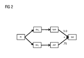
- Fig. 2 shows a multiple projection synthetic mammogram example as a combined projection image SM.
- the three-dimensional volumes RV1 and RV2 are reconstructed from the initial projections images PI in this example, e.g. by means of a microprocessor. While both reconstructed three-dimensional volumes RV1 and RV2 are done with the same kind of filtered back-projection (FBP) algorithm, the reconstructed volume RV1 is based on 25 projections and the reconstructed volume RV2 is based on a subset of only 3 central projections.
- the central projection directions as a subset from all projection directions are drawn with solid lines in Fig. 1 .
- the processed initial tomosynthesis projection images are transformed in a single re-projected image RP on the basis of single reconstructed volume RV.
- Fig. 3 shows a diagram of method steps for generating a combined projection image SM from a medical inspection object 101.
- step S101 a set of initial projection images PI is captured by the tomosynthesis acquisition. Capturing is can be done for example with a solid state X-ray detector.
- step S102 at least a first and a second three-dimensional volume RV1, RV2 are reconstructed from the set of initial projection images PI, e.g. by a means of a computer algorithm.
- Reconstructing essentially involves solving the inverse Radon transformation on the basis of the captured initial projection images.
- step S103 at least a first re-projection image RP1 is generated from the first three-dimensional volume RV1 and at least a second re-projection image RP2 is generated from the second three-dimensional volume RV2.
- Generating re-projection images can be performed by summing pixels on a virtual projection beam considering a particular geometry, like a cone beam.
- step S104 the first re-projection image RP1 and the second re-projection image RP2 is weighed. Weighting can be done either by independently weighting each pixel in the re-projection images RP1 and RP2 or by multiplying each of the entire re-projection images RP1 and RP2 with a weighting factor.
- step S105 the weighted first re-projection image RP1 and second re-projection image RP2 is combined, e.g. added or subtracted, for generating the combined projection image (SM).
- SM combined projection image
- Fig. 4 shows an imaging device 200 for generating the combined projection image SM from the medical inspection object 101.
- the imaging device 200 is for example a computer tomography apparatus.
- the imaging device comprises a capturing means 201 for capturing a set of initial projection images PI, e.g. an x-ray detector 105.
- a reconstruction means 203 serves for reconstructing at least a first and at least a second three-dimensional volume RV1, RV2 from the set of initial projection images PI by a mathematical calculation.
- a generation means 205 serves for generating at least a first re-projection image RP1 from the first three-dimensional volume RV1 and at least a second re-projection image RP2 from the second three-dimensional volume RV2 by a calculated re-projection.
- a weighting means 207 for weighting the first re-projection image RP1 and the second re-projection image RP2.
- the imaging device 200 comprises a combination means 209 for combining the weighted first re- projection image RP1 and second re-projection image RP2 for generating the combined projection image SM.
- the reconstruction means 203, the generation means 205, the weighting means 207 and the combination means 209 can be implemented by a computer with a microprocessor and a data storage that is capable of processing the captured initial projection images PI.
- Fig. 5 shows a principle of a multiple projection synthetic mammogram as a combined projection image.
- PI denotes initial projection images
- RV denotes reconstructed volumes
- RP denotes re-projection images
- SM denotes a combined projection image, like the synthetic mammogram.
- n reconstructed volumes RV 1 ... RV n with n>0 are given.
- n th reconstructed volume RV n m two-dimensional projection images RP mn on the same virtual detector are computed.
- the projections of the projection images RP mn may vary in type, e.g., Maximum-Intensity-Projection (MIP), Average-Intensity-Projection (AIP) and Highest-Interest-Projection (HIP) as well as projection geometry, e.g. orthographic, cone beam or fan beam.
- MIP Maximum-Intensity-Projection
- AIP Average-Intensity-Projection
- HIP Highest-Interest-Projection
- the re-projection images RP can be obtained from one or more reconstructed three-dimensional volumes RV.
- Multiple projections and/or multiple reconstructions can be used to synthesize a 2D mammogram as a combined projection image.
- advantages from different projections and reconstructions can be exploited to generate a synthetic mammogram that highlights diagnostically relevant features. Reconstructing the three dimensional volume RV from a subset of initial projections PI avoids accumulating artefacts when re-projecting.
- Fig. 6 shows examples for Average Intensity Projections (AIPs) from a reconstructed volume RV which has been reconstructed using 1, 3, 5 and all 25 projections respectively (from left to right).
- the medical inspection object 101 is a human breast.
- MIPs Maximum-Intensity-Projections
- the different kind of projections such as MIP and AIP but also different Highest-Interest-Projections (HIP) are wellsuited for highlighting particular diagnostically relevant structures.
- these projections exhibit differences regarding contrast-to-noise ratio and spatial noise homogeneity.
- different three-dimensional reconstructions RV with varying contrast, noise and artefact-behavior can also be constructed from the initial projection images PI. Differences may come from using different reconstruction algorithms (e.g. FBP - filtered back projection or IR - iterative reconstruction) or from different parameterizations (e.g. usage of different backprojection filters in FBP or different regularizers in IR).
- different reconstruction algorithms e.g. FBP - filtered back projection or IR - iterative reconstruction
- parameterizations e.g. usage of different backprojection filters in FBP or different regularizers in IR.
- Fig. 7 shows MIPs of a volume with 1, 3, 5, and 25 projections (from left to right). While the image noise decreases from left to right, the images also get increasingly blurred.
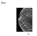
- Fig. 8 shows a synthetic mammogram on the basis of a weighted MIP (weighting factor: 1) from a reconstructed volume RV with 25 projections and a weighted AIP (weighting facto. 0.75) from a reconstructed volume RV with 3 projections.
- Weighted MIP weighting factor: 1
- AIP weighting facto. 0.75
Landscapes
- Engineering & Computer Science (AREA)
- Health & Medical Sciences (AREA)
- Life Sciences & Earth Sciences (AREA)
- Medical Informatics (AREA)
- Physics & Mathematics (AREA)
- Theoretical Computer Science (AREA)
- Pathology (AREA)
- Heart & Thoracic Surgery (AREA)
- High Energy & Nuclear Physics (AREA)
- Veterinary Medicine (AREA)
- Nuclear Medicine, Radiotherapy & Molecular Imaging (AREA)
- Optics & Photonics (AREA)
- Public Health (AREA)
- Radiology & Medical Imaging (AREA)
- Biomedical Technology (AREA)
- Biophysics (AREA)
- Molecular Biology (AREA)
- Surgery (AREA)
- Animal Behavior & Ethology (AREA)
- General Health & Medical Sciences (AREA)
- General Physics & Mathematics (AREA)
- Computer Vision & Pattern Recognition (AREA)
- Pulmonology (AREA)
- Apparatus For Radiation Diagnosis (AREA)
- Image Processing (AREA)
Abstract
Description
- The present invention relates to a method for generating a combined projection image (SM) from a medical inspection object and an imaging device for generating a combined projection image (SM) from a medical inspection object.
- Computed tomography (CT), usually X-ray computed tomography, is a widely-used medical diagnostic tool, which allows the generation of tomographic images or slices of an area of interest in a patient. Radiologists often prefer using thick slab or thick-slice volume for diagnostic and screening reading. For example, 5.0 mm slabs are often used for clinical reading and data storage in thoracic CT, although thin, high resolution 0.5 mm slabs are available and used for computer applications such as three-dimensional volume rendering and computer aided diagnosis algorithms.
- It is relatively easy to compute 3.0 - 5.0 mm slabs in thoracic CT images without losing diagnostically relevant information, for example by applying methods such as Average Intensity Projection (AIP) or Maximum Intensity Projection (MIP). The slab thickness is related to the combined thickness of the original slices in the volume. Generally, a slab is rendered as a two-dimensional image, so that the image can be printed or viewed on a computer screen.
- In Digital Breast Tomosynthesis (DBT) data volumes are often reconstructed at a higher resolution, for example at a resolution of 85 microns for a slice thickness of 1.0 mm. Such a high-resolution volume allows visualization of the fine clinical details required for accurate medical diagnosis of breast cancer, for example microcalcifications of only 100 microns in size, very fine spiculations of masses, etc. A correct depiction of microcalcification morphology and spiculations is critical for the radiologist in order to be able to differentiate between benign and malignant lesions in breast tissue. This means that the amount of data in DBT volumes is very large. For example, the total volume of data for a single patient (e.g. including two DBT views and projection images) can exceed one gigabyte. The large data volume complicates data transfer and increases radiologist workload.
- Another reason for generating slabs from the initial data is that a radiologist often needs to evaluate the distribution of an entire cluster of calcifications embedded in the surrounding tissue, including any masses and architectural distortions in that region.
- In breast tissue, a lesion can often extend over 10.0 mm or more, and can extend in any random direction. Therefore, in order to be able to perform such an evaluation, a radiologist should be provided with very thick slabs, i.e. slabs with a thickness in excess of 10.0 mm. In some cases, it might be desirable to perform such an evaluation over the total volume (essentially the whole volume collapsed into a single slab). In the context of DBT such a single slab has also been called synthetic mammogram (SM) due to its similarity to conventional 2D mammograms.
- It is an object of the present invention to produce a projection image from a medical object with high sharpness and contrast.
- In a first aspect this object is solved by a method for generating a combined projection image from a medical inspection object, comprising the steps of capturing a set of initial projection images; reconstructing a first and a second three-dimensional volume from the set of initial projection images; generating a first re-projection image from the first three-dimensional volume and a second re-projection image from the second three-dimensional volume; weighting the first re-projection image and the second re-projection image; and combining the weighted first re-projection image and second re-projection image for generating the combined projection image. By the method the quality of the combined projection image is improved and noise is reduced. Diagnostically relevant information can be highlighted while image information with less relevance is down-weighed.
- In a preferred embodiment of the method the first and/or second re-projection image is generated under an orthographic projection geometry, cone beam projection geometry or fan beam projection geometry from the first and/or second three-dimensional volume. In this embodiment geometries are employed that increase sharpness of the combined projection image.
- In a further preferred embodiment of the method the first re-projection image and second re-projection image are linearly combined for generating the combined projection image. In this embodiment the combined projection image can be generated with few computational steps.
- In a further preferred embodiment of the method reconstructing the first and second three-dimensional volume is based on a filtered back-projection algorithm. In this embodiment the three-dimensional volumes can be generated efficiently.
- In a further preferred embodiment of the method the first or/and second three-dimensional volume are reconstructed from a reduced subset of initial projection images. In this embodiment an accumulation of artefacts can be avoided.
- In a further preferred embodiment of the method the reduced subset of initial projection images comprises a number of initial projection images from view positions adjacent to the re-projection view position. In this embodiment a blurring is avoided to a great extent.
- In a further preferred embodiment of the method the first and/or second re-projection image is generated by a maximum intensity projection, an average intensity projection or a highest-interest-projection from the first and/or second three-dimensional volume. In this embodiment projections are used that produce projection images with high contrast.
- In a further preferred embodiment of the method capturing a set of initial projection images is based on x-ray imaging from different angles on a circular trajectory. In this embodiment initial images are captured from which the three-dimensional volumes can be constructed efficiently.
- In a further preferred embodiment of the method capturing a set of initial projection images is based on a tomosynthesis acquisition. In this embodiment three-dimensional volumes can be reconstructed easily.
- In a further preferred embodiment of the method the tomosynthesis acquisition is performed by a computer tomography apparatus. In this embodiment is well suited for investigating medical inspection objects.
- In a further preferred embodiment of the method each pixel in the first re-projection image and the second re-projection is weighted independently. In this embodiment contrast and sharpness can be increased to a large extend.
- In a further preferred embodiment of the method weighting is performed by multiplying the first and/or the second re-projection image with a weighting factor. In this embodiment weighting can be performed quick and with low complexity.
- In a further preferred embodiment of the method the initial projection images, the reconstructed volumes, the re-projection images and/or the combined projection image are noise filtered. In this embodiment the quality of the resulting combined projection image is improved.
- In a second aspect this object is solved by a method for generating a combined projection image from a medical inspection object, comprising the steps of capturing a set of initial projection images; reconstructing a three-dimensional volume from the set of initial projection images; generating a first re-projection image and a second re-projection image from the three-dimensional volume; weighting the first re-projection image and the second re-projection image; and combining the weighted first re-projection image and second re-projection image for generating the combined projection image. In this embodiment same advantages as in the method according to the first aspect are achieved.
- In a third aspect this object is solved by an imaging device for generating a combined projection image from a medical inspection object, comprising a capturing means for capturing a set of initial projection images; a reconstruction means for reconstructing a first and a second three-dimensional volume from the set of initial projection images; a generation means for generating a first re-projection image from the first three-dimensional volume and a second re-projection image from the second three-dimensional volume; a weighting means for weighting the first re-projection image and the second re-projection image; and a combination means for combining the weighted first re-projection image and second re-projection image for generating the combined projection image. In this embodiment same advantages as in the method according to the first aspect are achieved.
- Further features, details and advantages of the aforementioned subject-matter are shown in the figures and described below.
- Fig. 1
- shows a schematic view of a tomosynthesis acquisition;
- Fig. 2
- shows a multiple projection synthetic mammogram example;
- Fig. 3
- shows a diagram of method steps;
- Fig. 4
- shows an imaging device;
- Fig. 5
- shows a principle of multiple projection synthetic mammogram;
- Fig. 6
- shows AIP projections of a reconstructed volume;
- Fig. 7
- shows MIP projections of a reconstructed volume; and
- Fig. 8
- shows a synthetic mammogram.
-
Fig. 1 shows a schematic view of a tomosynthesis acquisition. The medical inspection object 101 (compressed breast) is imaged with x-ray from different angles on a circular trajectory. The breast is compressed by acompression paddle 107. X-Ray projection images of themedical inspection object 101 are captured by thex-ray detector 105. - The
X-ray source 103 is moved on a circular path around themedical inspection object 101 in order to capture initial projection images PI from different projection directions by thex-ray detector 105. Thex-ray detector 105 is positioned on the opposite side of the circle from theX-ray source 103. - X-ray computed tomography (x-ray CT) is a technology that uses computer-processed x-rays to produce tomographic images (virtual 'slices') of specific areas of the scanned object, allowing a user to see what is inside it without cutting it open.
- Digital geometry processing is used to generate a three-dimensional volume of the inside of the
medical inspection object 105 from a large series of two-dimensional radiographic initial projection images PI captured around a single axis of rotation. Medical imaging is a common application of x-ray CT. Its cross-sectional images are used for diagnostic and therapeutic purposes in various medical disciplines. -
Fig. 2 shows a multiple projection synthetic mammogram example as a combined projection image SM. The three-dimensional volumes RV1 and RV2 are reconstructed from the initial projections images PI in this example, e.g. by means of a microprocessor. While both reconstructed three-dimensional volumes RV1 and RV2 are done with the same kind of filtered back-projection (FBP) algorithm, the reconstructed volume RV1 is based on 25 projections and the reconstructed volume RV2 is based on a subset of only 3 central projections. The central projection directions as a subset from all projection directions are drawn with solid lines inFig. 1 . While the reconstructed volume RV2 from the central projections is expected to exhibit more noise and more severe out-of-plane artefacts, the angles at which these artefacts occur are narrower. This causes less blurring from the out-of-plane artefacts, when re-projecting these volumes. - The processed initial tomosynthesis projection images are transformed in a single re-projected image RP on the basis of single reconstructed volume RV.
-
Fig. 3 shows a diagram of method steps for generating a combined projection image SM from amedical inspection object 101. In step S101 a set of initial projection images PI is captured by the tomosynthesis acquisition. Capturing is can be done for example with a solid state X-ray detector. - In step S102 at least a first and a second three-dimensional volume RV1, RV2 are reconstructed from the set of initial projection images PI, e.g. by a means of a computer algorithm. Reconstructing essentially involves solving the inverse Radon transformation on the basis of the captured initial projection images.
- Then in step S103 at least a first re-projection image RP1 is generated from the first three-dimensional volume RV1 and at least a second re-projection image RP2 is generated from the second three-dimensional volume RV2. Generating re-projection images can be performed by summing pixels on a virtual projection beam considering a particular geometry, like a cone beam.
- In step S104 the first re-projection image RP1 and the second re-projection image RP2 is weighed. Weighting can be done either by independently weighting each pixel in the re-projection images RP1 and RP2 or by multiplying each of the entire re-projection images RP1 and RP2 with a weighting factor.
- Finally in step S105 the weighted first re-projection image RP1 and second re-projection image RP2 is combined, e.g. added or subtracted, for generating the combined projection image (SM).
-
Fig. 4 shows animaging device 200 for generating the combined projection image SM from themedical inspection object 101. Theimaging device 200 is for example a computer tomography apparatus. The imaging device comprises a capturing means 201 for capturing a set of initial projection images PI, e.g. anx-ray detector 105. A reconstruction means 203 serves for reconstructing at least a first and at least a second three-dimensional volume RV1, RV2 from the set of initial projection images PI by a mathematical calculation. A generation means 205 serves for generating at least a first re-projection image RP1 from the first three-dimensional volume RV1 and at least a second re-projection image RP2 from the second three-dimensional volume RV2 by a calculated re-projection. A weighting means 207 for weighting the first re-projection image RP1 and the second re-projection image RP2. Finally theimaging device 200 comprises a combination means 209 for combining the weighted first re- projection image RP1 and second re-projection image RP2 for generating the combined projection image SM. - The reconstruction means 203, the generation means 205, the weighting means 207 and the combination means 209 can be implemented by a computer with a microprocessor and a data storage that is capable of processing the captured initial projection images PI.
-
Fig. 5 shows a principle of a multiple projection synthetic mammogram as a combined projection image. PI denotes initial projection images, RV denotes reconstructed volumes, RP denotes re-projection images, and SM denotes a combined projection image, like the synthetic mammogram. - From the initial projection images PI captured by the detector 105 n three-dimensional volumes RV1 ... RVn are reconstructed. Thus n reconstructed volumes RV1 ... RVn with n>0 are given. From the nth reconstructed volume RVn m two-dimensional projection images RPmn on the same virtual detector are computed. The projections of the projection images RPmn may vary in type, e.g., Maximum-Intensity-Projection (MIP), Average-Intensity-Projection (AIP) and Highest-Interest-Projection (HIP) as well as projection geometry, e.g. orthographic, cone beam or fan beam.
- The synthetic mammogram SM as combined projection image is computed as linear combination of the re-projection images RPmn, for example by:

where N>0,
- This produces a weighted linear combination of multiple re-projection images RP, in which the weights can be chosen independently for each pixel in each projection image. The re-projection images RP can be obtained from one or more reconstructed three-dimensional volumes RV.
- Instead of the linear combination described in Eqn (1), other ways of combining/mixing of re-projection images are conceivable. In addition filtering of the initial projection images PI, the reconstructed volumes RV, the re-projection images RP and/or the combined projection image SM can improve the final result.
- Multiple projections and/or multiple reconstructions can be used to synthesize a 2D mammogram as a combined projection image. In particular, advantages from different projections and reconstructions can be exploited to generate a synthetic mammogram that highlights diagnostically relevant features. Reconstructing the three dimensional volume RV from a subset of initial projections PI avoids accumulating artefacts when re-projecting.
-
Fig. 6 shows examples for Average Intensity Projections (AIPs) from a reconstructed volume RV which has been reconstructed using 1, 3, 5 and all 25 projections respectively (from left to right). Themedical inspection object 101 is a human breast. - While the contrast-to-noise ratio improves with the number of projection images PI, structures tend to get more and more blurred. While the image noise decreases from left to right, the images also get increasingly blurred.
- A similar tendency can be seen for the Maximum-Intensity-Projections (MIPs) in
Fig. 5 . Due to the different noise behavior of AIPs and MIPs, however, for a MIP preferably a volume reconstructed with all projections is used, while for the AIP, a volume reconstructed with a subset of less projections, for example 3, is preferred. - The different kind of projections, such as MIP and AIP but also different Highest-Interest-Projections (HIP) are wellsuited for highlighting particular diagnostically relevant structures. In particular, these projections exhibit differences regarding contrast-to-noise ratio and spatial noise homogeneity.
- However, different three-dimensional reconstructions RV with varying contrast, noise and artefact-behavior can also be constructed from the initial projection images PI. Differences may come from using different reconstruction algorithms (e.g. FBP - filtered back projection or IR - iterative reconstruction) or from different parameterizations (e.g. usage of different backprojection filters in FBP or different regularizers in IR).
-
Fig. 7 shows MIPs of a volume with 1, 3, 5, and 25 projections (from left to right). While the image noise decreases from left to right, the images also get increasingly blurred. -
Fig. 8 shows a synthetic mammogram on the basis of a weighted MIP (weighting factor: 1) from a reconstructed volume RV with 25 projections and a weighted AIP (weighting facto. 0.75) from a reconstructed volume RV with 3 projections. Mixing the re-projection images RP leads to sharper combined projection images SM with more details. - The scope of the invention is defined by the claims and is not restricted by special features discussed in the description or shown in the figures. All features discussed with respect to different embodiments can be combined variously and independently in order to simultaneously realize their technical effect.
-
- 101
- medical inspection object
- 103
- x-ray source
- 105
- detector
- 107
- compression paddle
- 200
- imaging device
- 201
- capturing means
- 203
- reconstruction means
- 205
- generation means
- 207
- weighting means
- 209
- combination means
- PI
- initial projection images
- RV
- reconstructed three-dimensional volume
- RP
- re-projection image
- SM
- combined projection image / synthetic mammogram
Claims (15)
- Method for generating a combined projection image (SM) from a medical inspection object (101), comprising the steps of:- capturing (S101) a set of initial projection images (PI) ;- reconstructing (S102) a first and a second three-dimensional volume (RV1, RV2) from the set of initial projection images (PI);- generating (S103) a first re-projection image (RP1) from the first three-dimensional volume (RV1) and a second re-projection image (RP2) from the second three-dimensional volume (RV2);- weighting (S104) the first re-projection image (RP1) and the second re-projection image (RP2); and- combining (S105) the weighted first re-projection image (RP1) and second re-projection image (RP2) for generating the combined projection image (SM).
- Method according to claim 1, wherein the first and/or second re-projection image (RP1, RP2) is generated under a orthographic projection geometry, cone beam projection geometry or fan beam projection geometry from the first and/or second three-dimensional volume (RV1, RV2).
- Method according to one of the proceeding claims, wherein the first re-projection image (RP1) and second re-projection image (RP2) are linearly combined for generating the combined projection image (SM).
- Method according to one of the proceeding claims, wherein reconstructing the first and second three-dimensional volume (RV1,RV2) is based on a filtered back-projection algorithm.
- Method according to one of the proceeding claims, wherein the first or/and second three-dimensional volume (RV1, RV2) are reconstructed from a reduced subset of initial projection images (PI).
- Method according to claim 5, wherein the reduced subset of initial projection images (PI) comprises a number initial projection images (PI) from views adjacent to the re-projection view.
- Method according to one of the proceeding claims, wherein the first and/or second re-projection image (RP1, RP2) is generated by a maximum intensity projection, an average intensity projection or a highest-interest-projection from the first and/or second three-dimensional volume (RV1, RV2).
- Method according to one of the proceeding claims, wherein capturing a set of initial projection images (PI) is based on x-ray imaging from different angles on a circular trajectory.
- Method according to one of the proceeding claims, wherein capturing a set of initial projection images (PI) is based on a tomosynthesis acquisition.
- Method according to claim 9, wherein the tomosynthesis acquisition is performed by a computer tomography apparatus.
- Method according to one of the proceeding claims, wherein each pixel in the first re-projection image (RP1) and the second re-projection (RP2) is weighted independently.
- Method according to one of the proceeding claims, wherein weighting is performed by multiplying the first and/or the second re-projection image (RP1, RP2) with a weighting factor.
- Method according to one of the proceeding claims, wherein the initial projection images (PI), the reconstructed volumes (RV), the re-projection images (RP) and/or the combined projection image (SM) are noise filtered.
- Method for generating a combined projection image (SM) from a medical inspection object (101), comprising the steps of:- capturing a set of initial projection images (PI);- reconstructing a three-dimensional volume (RV1, RV2) from the set of initial projection images (PI);- generating a first re-projection image (RP1) and a second re-projection image (RP2) from the three-dimensional volume (RV1);- weighting the first re-projection image (RP1) and the second re-projection image (RP2); and- combining the weighted first re-projection image (RP1) and second re-projection image (RP2) for generating the combined projection image (SM).
- Imaging device (200) for generating a combined projection image (SM) from a medical inspection object (101), comprising:- a capturing means (201) for capturing a set of initial projection images (PI);- a reconstruction means (203) for reconstructing a first and a second three-dimensional volume (RV1, RV2) from the set of initial projection images (PI);- a generation means (205) for generating a first re-projection image (RP1) from the first three-dimensional volume (RV1) and a second re-projection image (RP2) from the second three-dimensional volume (RV2);- a weighting means (207) for weighting the first re-projection image (RP1) and the second re-projection image (RP2); and- a combination means (209) for combining the weighted first re- projection image (RP1) and second re-projection image (RP2) for generating the combined projection image (SM).
Applications Claiming Priority (1)
| Application Number | Priority Date | Filing Date | Title |
|---|---|---|---|
| US14/490,917 US9836858B2 (en) | 2014-09-19 | 2014-09-19 | Method for generating a combined projection image and imaging device |
Publications (3)
| Publication Number | Publication Date |
|---|---|
| EP2998936A2 true EP2998936A2 (en) | 2016-03-23 |
| EP2998936A3 EP2998936A3 (en) | 2016-04-06 |
| EP2998936B1 EP2998936B1 (en) | 2017-04-05 |
Family
ID=53836437
Family Applications (1)
| Application Number | Title | Priority Date | Filing Date |
|---|---|---|---|
| EP15180132.1A Active EP2998936B1 (en) | 2014-09-19 | 2015-08-07 | Method for generating a combined projection image |
Country Status (2)
| Country | Link |
|---|---|
| US (1) | US9836858B2 (en) |
| EP (1) | EP2998936B1 (en) |
Families Citing this family (5)
| Publication number | Priority date | Publication date | Assignee | Title |
|---|---|---|---|---|
| DE102013211547B3 (en) * | 2013-06-19 | 2014-05-22 | Siemens Aktiengesellschaft | Method for producing tomo-synthetic X-ray image of breast of patient, involves producing difference image from synthetic projection image and projection image by subtraction, and using difference image for reconstructing X-ray image |
| EP3518182B1 (en) * | 2018-01-26 | 2022-05-18 | Siemens Healthcare GmbH | Tilted slices in dbt |
| EP3657442B1 (en) | 2018-11-23 | 2022-10-26 | Siemens Healthcare GmbH | Synthetic mammogramm with embossed image impression |
| CN109741434B (en) * | 2018-12-28 | 2022-11-01 | 深圳安科高技术股份有限公司 | Volume-driven projection method and system |
| CN110189386B (en) * | 2019-05-06 | 2023-05-26 | 上海联影医疗科技股份有限公司 | Medical image processing method, device, storage medium and computer equipment |
Family Cites Families (12)
| Publication number | Priority date | Publication date | Assignee | Title |
|---|---|---|---|---|
| US6850587B1 (en) * | 2001-10-24 | 2005-02-01 | Analogic Corporation | Reprojection-based three-dimensional image reconstruction |
| US20080187195A1 (en) * | 2005-04-14 | 2008-08-07 | Koninklijke Philips Electronics N. V. | Image Processing System, Particularly for Circular and Helical Cone-Beam Ct |
| WO2008012754A2 (en) | 2006-07-25 | 2008-01-31 | Koninklijke Philips Electronics N.V. | Volumetric data projection |
| US8223916B2 (en) * | 2009-03-31 | 2012-07-17 | Hologic, Inc. | Computer-aided detection of anatomical abnormalities in x-ray tomosynthesis images |
| US8654119B2 (en) * | 2009-08-17 | 2014-02-18 | Mistretta Medical, Llc | System and method for four dimensional angiography and fluoroscopy |
| US8346007B2 (en) * | 2009-12-22 | 2013-01-01 | Carestream Health, Inc. | Noise suppression in cone beam CT projection data |
| WO2011100511A2 (en) * | 2010-02-11 | 2011-08-18 | University Of Michigan | Methods for microcalification detection of breast cancer on digital tomosynthesis mammograms |
| DE102010024684B8 (en) * | 2010-06-23 | 2019-08-22 | Siemens Healthcare Gmbh | Method for reconstructing image data of a moving examination object, control and processing unit, computer tomography system and computer program |
| FR2967520B1 (en) * | 2010-11-16 | 2012-12-21 | Gen Electric | METHOD FOR PROCESSING RADIOLOGICAL IMAGES OF A PATIENT |
| DE102011003137A1 (en) | 2011-01-25 | 2012-07-26 | Siemens Aktiengesellschaft | Imaging method with an improved representation of a tissue area |
| DE102011087337B4 (en) * | 2011-11-29 | 2016-10-13 | Siemens Healthcare Gmbh | A method of reconstructing a reconstruction data set containing two-dimensional virtual X-ray images |
| US9489752B2 (en) * | 2012-11-21 | 2016-11-08 | General Electric Company | Ordered subsets with momentum for X-ray CT image reconstruction |
-
2014
- 2014-09-19 US US14/490,917 patent/US9836858B2/en active Active
-
2015
- 2015-08-07 EP EP15180132.1A patent/EP2998936B1/en active Active
Non-Patent Citations (1)
| Title |
|---|
| None |
Also Published As
| Publication number | Publication date |
|---|---|
| EP2998936A3 (en) | 2016-04-06 |
| EP2998936B1 (en) | 2017-04-05 |
| US9836858B2 (en) | 2017-12-05 |
| US20160086356A1 (en) | 2016-03-24 |
Similar Documents
| Publication | Publication Date | Title |
|---|---|---|
| Mertelmeier et al. | Optimizing filtered backprojection reconstruction for a breast tomosynthesis prototype device | |
| Wu et al. | A comparison of reconstruction algorithms for breast tomosynthesis | |
| JP6457946B2 (en) | System and method for improving workflow efficiency in tomosynthesis medical image data interpretation | |
| JP6766045B2 (en) | How to generate a synthetic mammogram from tomosynthesis data | |
| US9836872B2 (en) | Methods for generation of edge=preserving synthetic mammograms from tomosynthesis data | |
| Dobbins III et al. | Digital x-ray tomosynthesis: current state of the art and clinical potential | |
| JP4965433B2 (en) | Cone beam CT apparatus using truncated projection and pre-acquired 3D CT image | |
| US8798353B2 (en) | Apparatus and method for two-view tomosynthesis imaging | |
| JP5348855B2 (en) | Object image reconstruction method and apparatus for performing the method | |
| EP2341482A2 (en) | Single screen multi-modality imaging displays | |
| CN112770674A (en) | System and method for image generation for synthesizing breast tissue by high density elemental suppression | |
| JP2016534802A (en) | Method and apparatus for displaying medical images | |
| EP2998936B1 (en) | Method for generating a combined projection image | |
| US6751284B1 (en) | Method and system for tomosynthesis image enhancement using transverse filtering | |
| US20120189091A1 (en) | Imaging Method for Rotating a Tissue Region | |
| GB2533801A (en) | Method and system for tomosynthesis projection images enhancement | |
| EP3232936B1 (en) | Method and system for processing tomosynthesis data | |
| CN102293660A (en) | Temporal resolution in cardio CT | |
| Kuo et al. | Dynamic reconstruction and rendering of 3D tomosynthesis images | |
| KR20220038101A (en) | SYSTEMS AND METHODS FOR GENERATING MULTI-VIEW SYNTHETIC DENTAL RADIOGRAPHS FOR INTRAORAL TOMOSYNTHESIS | |
| Ludwig et al. | A novel approach for filtered backprojection in tomosynthesis based on filter kernels determined by iterative reconstruction techniques | |
| Orman et al. | Adaptation of image quality using various filter setups in the filtered backprojection approach for digital breast tomosynthesis | |
| Kim et al. | Generation of conspicuity-improved synthetic image from digital breast tomosynthesis | |
| Oh et al. | Application of digital tomosynthesis (DTS) of optimal deblurring filters for dental x-ray imaging | |
| Dennerlein et al. | Efficient synthesis of virtual projections from a tomosynthesis data set using a 2D image processing method |
Legal Events
| Date | Code | Title | Description |
|---|---|---|---|
| PUAL | Search report despatched |
Free format text: ORIGINAL CODE: 0009013 |
|
| PUAI | Public reference made under article 153(3) epc to a published international application that has entered the european phase |
Free format text: ORIGINAL CODE: 0009012 |
|
| AK | Designated contracting states |
Kind code of ref document: A2 Designated state(s): AL AT BE BG CH CY CZ DE DK EE ES FI FR GB GR HR HU IE IS IT LI LT LU LV MC MK MT NL NO PL PT RO RS SE SI SK SM TR |
|
| AX | Request for extension of the european patent |
Extension state: BA ME |
|
| AK | Designated contracting states |
Kind code of ref document: A3 Designated state(s): AL AT BE BG CH CY CZ DE DK EE ES FI FR GB GR HR HU IE IS IT LI LT LU LV MC MK MT NL NO PL PT RO RS SE SI SK SM TR |
|
| AX | Request for extension of the european patent |
Extension state: BA ME |
|
| RIC1 | Information provided on ipc code assigned before grant |
Ipc: G06T 11/00 20060101AFI20160303BHEP Ipc: G06T 15/08 20110101ALI20160303BHEP |
|
| RAP1 | Party data changed (applicant data changed or rights of an application transferred) |
Owner name: SIEMENS HEALTHCARE GMBH |
|
| 17P | Request for examination filed |
Effective date: 20160906 |
|
| RBV | Designated contracting states (corrected) |
Designated state(s): AL AT BE BG CH CY CZ DE DK EE ES FI FR GB GR HR HU IE IS IT LI LT LU LV MC MK MT NL NO PL PT RO RS SE SI SK SM TR |
|
| GRAP | Despatch of communication of intention to grant a patent |
Free format text: ORIGINAL CODE: EPIDOSNIGR1 |
|
| RIC1 | Information provided on ipc code assigned before grant |
Ipc: G06T 11/00 20060101AFI20160923BHEP |
|
| INTG | Intention to grant announced |
Effective date: 20161028 |
|
| GRAS | Grant fee paid |
Free format text: ORIGINAL CODE: EPIDOSNIGR3 |
|
| GRAA | (expected) grant |
Free format text: ORIGINAL CODE: 0009210 |
|
| AK | Designated contracting states |
Kind code of ref document: B1 Designated state(s): AL AT BE BG CH CY CZ DE DK EE ES FI FR GB GR HR HU IE IS IT LI LT LU LV MC MK MT NL NO PL PT RO RS SE SI SK SM TR |
|
| REG | Reference to a national code |
Ref country code: GB Ref legal event code: FG4D |
|
| REG | Reference to a national code |
Ref country code: CH Ref legal event code: EP |
|
| REG | Reference to a national code |
Ref country code: AT Ref legal event code: REF Ref document number: 882449 Country of ref document: AT Kind code of ref document: T Effective date: 20170415 |
|
| REG | Reference to a national code |
Ref country code: IE Ref legal event code: FG4D |
|
| REG | Reference to a national code |
Ref country code: DE Ref legal event code: R096 Ref document number: 602015002116 Country of ref document: DE |
|
| REG | Reference to a national code |
Ref country code: NL Ref legal event code: MP Effective date: 20170405 |
|
| REG | Reference to a national code |
Ref country code: FR Ref legal event code: PLFP Year of fee payment: 3 |
|
| REG | Reference to a national code |
Ref country code: LT Ref legal event code: MG4D |
|
| REG | Reference to a national code |
Ref country code: AT Ref legal event code: MK05 Ref document number: 882449 Country of ref document: AT Kind code of ref document: T Effective date: 20170405 |
|
| PG25 | Lapsed in a contracting state [announced via postgrant information from national office to epo] |
Ref country code: NL Free format text: LAPSE BECAUSE OF FAILURE TO SUBMIT A TRANSLATION OF THE DESCRIPTION OR TO PAY THE FEE WITHIN THE PRESCRIBED TIME-LIMIT Effective date: 20170405 |
|
| PG25 | Lapsed in a contracting state [announced via postgrant information from national office to epo] |
Ref country code: ES Free format text: LAPSE BECAUSE OF FAILURE TO SUBMIT A TRANSLATION OF THE DESCRIPTION OR TO PAY THE FEE WITHIN THE PRESCRIBED TIME-LIMIT Effective date: 20170405 Ref country code: HR Free format text: LAPSE BECAUSE OF FAILURE TO SUBMIT A TRANSLATION OF THE DESCRIPTION OR TO PAY THE FEE WITHIN THE PRESCRIBED TIME-LIMIT Effective date: 20170405 Ref country code: NO Free format text: LAPSE BECAUSE OF FAILURE TO SUBMIT A TRANSLATION OF THE DESCRIPTION OR TO PAY THE FEE WITHIN THE PRESCRIBED TIME-LIMIT Effective date: 20170705 Ref country code: GR Free format text: LAPSE BECAUSE OF FAILURE TO SUBMIT A TRANSLATION OF THE DESCRIPTION OR TO PAY THE FEE WITHIN THE PRESCRIBED TIME-LIMIT Effective date: 20170706 Ref country code: AT Free format text: LAPSE BECAUSE OF FAILURE TO SUBMIT A TRANSLATION OF THE DESCRIPTION OR TO PAY THE FEE WITHIN THE PRESCRIBED TIME-LIMIT Effective date: 20170405 Ref country code: FI Free format text: LAPSE BECAUSE OF FAILURE TO SUBMIT A TRANSLATION OF THE DESCRIPTION OR TO PAY THE FEE WITHIN THE PRESCRIBED TIME-LIMIT Effective date: 20170405 Ref country code: LT Free format text: LAPSE BECAUSE OF FAILURE TO SUBMIT A TRANSLATION OF THE DESCRIPTION OR TO PAY THE FEE WITHIN THE PRESCRIBED TIME-LIMIT Effective date: 20170405 |
|
| PG25 | Lapsed in a contracting state [announced via postgrant information from national office to epo] |
Ref country code: SE Free format text: LAPSE BECAUSE OF FAILURE TO SUBMIT A TRANSLATION OF THE DESCRIPTION OR TO PAY THE FEE WITHIN THE PRESCRIBED TIME-LIMIT Effective date: 20170405 Ref country code: LV Free format text: LAPSE BECAUSE OF FAILURE TO SUBMIT A TRANSLATION OF THE DESCRIPTION OR TO PAY THE FEE WITHIN THE PRESCRIBED TIME-LIMIT Effective date: 20170405 Ref country code: RS Free format text: LAPSE BECAUSE OF FAILURE TO SUBMIT A TRANSLATION OF THE DESCRIPTION OR TO PAY THE FEE WITHIN THE PRESCRIBED TIME-LIMIT Effective date: 20170405 Ref country code: BG Free format text: LAPSE BECAUSE OF FAILURE TO SUBMIT A TRANSLATION OF THE DESCRIPTION OR TO PAY THE FEE WITHIN THE PRESCRIBED TIME-LIMIT Effective date: 20170705 Ref country code: PL Free format text: LAPSE BECAUSE OF FAILURE TO SUBMIT A TRANSLATION OF THE DESCRIPTION OR TO PAY THE FEE WITHIN THE PRESCRIBED TIME-LIMIT Effective date: 20170405 Ref country code: IS Free format text: LAPSE BECAUSE OF FAILURE TO SUBMIT A TRANSLATION OF THE DESCRIPTION OR TO PAY THE FEE WITHIN THE PRESCRIBED TIME-LIMIT Effective date: 20170805 |
|
| REG | Reference to a national code |
Ref country code: DE Ref legal event code: R097 Ref document number: 602015002116 Country of ref document: DE |
|
| PG25 | Lapsed in a contracting state [announced via postgrant information from national office to epo] |
Ref country code: RO Free format text: LAPSE BECAUSE OF FAILURE TO SUBMIT A TRANSLATION OF THE DESCRIPTION OR TO PAY THE FEE WITHIN THE PRESCRIBED TIME-LIMIT Effective date: 20170405 Ref country code: DK Free format text: LAPSE BECAUSE OF FAILURE TO SUBMIT A TRANSLATION OF THE DESCRIPTION OR TO PAY THE FEE WITHIN THE PRESCRIBED TIME-LIMIT Effective date: 20170405 Ref country code: SK Free format text: LAPSE BECAUSE OF FAILURE TO SUBMIT A TRANSLATION OF THE DESCRIPTION OR TO PAY THE FEE WITHIN THE PRESCRIBED TIME-LIMIT Effective date: 20170405 Ref country code: EE Free format text: LAPSE BECAUSE OF FAILURE TO SUBMIT A TRANSLATION OF THE DESCRIPTION OR TO PAY THE FEE WITHIN THE PRESCRIBED TIME-LIMIT Effective date: 20170405 Ref country code: CZ Free format text: LAPSE BECAUSE OF FAILURE TO SUBMIT A TRANSLATION OF THE DESCRIPTION OR TO PAY THE FEE WITHIN THE PRESCRIBED TIME-LIMIT Effective date: 20170405 |
|
| PLBE | No opposition filed within time limit |
Free format text: ORIGINAL CODE: 0009261 |
|
| STAA | Information on the status of an ep patent application or granted ep patent |
Free format text: STATUS: NO OPPOSITION FILED WITHIN TIME LIMIT |
|
| PG25 | Lapsed in a contracting state [announced via postgrant information from national office to epo] |
Ref country code: IT Free format text: LAPSE BECAUSE OF FAILURE TO SUBMIT A TRANSLATION OF THE DESCRIPTION OR TO PAY THE FEE WITHIN THE PRESCRIBED TIME-LIMIT Effective date: 20170405 Ref country code: SM Free format text: LAPSE BECAUSE OF FAILURE TO SUBMIT A TRANSLATION OF THE DESCRIPTION OR TO PAY THE FEE WITHIN THE PRESCRIBED TIME-LIMIT Effective date: 20170405 |
|
| 26N | No opposition filed |
Effective date: 20180108 |
|
| PG25 | Lapsed in a contracting state [announced via postgrant information from national office to epo] |
Ref country code: MC Free format text: LAPSE BECAUSE OF FAILURE TO SUBMIT A TRANSLATION OF THE DESCRIPTION OR TO PAY THE FEE WITHIN THE PRESCRIBED TIME-LIMIT Effective date: 20170405 |
|
| REG | Reference to a national code |
Ref country code: BE Ref legal event code: MM Effective date: 20170831 |
|
| REG | Reference to a national code |
Ref country code: IE Ref legal event code: MM4A |
|
| PG25 | Lapsed in a contracting state [announced via postgrant information from national office to epo] |
Ref country code: SI Free format text: LAPSE BECAUSE OF FAILURE TO SUBMIT A TRANSLATION OF THE DESCRIPTION OR TO PAY THE FEE WITHIN THE PRESCRIBED TIME-LIMIT Effective date: 20170405 |
|
| PG25 | Lapsed in a contracting state [announced via postgrant information from national office to epo] |
Ref country code: LU Free format text: LAPSE BECAUSE OF NON-PAYMENT OF DUE FEES Effective date: 20170807 |
|
| PG25 | Lapsed in a contracting state [announced via postgrant information from national office to epo] |
Ref country code: IE Free format text: LAPSE BECAUSE OF NON-PAYMENT OF DUE FEES Effective date: 20170807 |
|
| REG | Reference to a national code |
Ref country code: FR Ref legal event code: PLFP Year of fee payment: 4 |
|
| PG25 | Lapsed in a contracting state [announced via postgrant information from national office to epo] |
Ref country code: BE Free format text: LAPSE BECAUSE OF NON-PAYMENT OF DUE FEES Effective date: 20170831 |
|
| PG25 | Lapsed in a contracting state [announced via postgrant information from national office to epo] |
Ref country code: MT Free format text: LAPSE BECAUSE OF NON-PAYMENT OF DUE FEES Effective date: 20170807 |
|
| REG | Reference to a national code |
Ref country code: CH Ref legal event code: PL |
|
| PG25 | Lapsed in a contracting state [announced via postgrant information from national office to epo] |
Ref country code: LI Free format text: LAPSE BECAUSE OF NON-PAYMENT OF DUE FEES Effective date: 20180831 Ref country code: CH Free format text: LAPSE BECAUSE OF NON-PAYMENT OF DUE FEES Effective date: 20180831 |
|
| PG25 | Lapsed in a contracting state [announced via postgrant information from national office to epo] |
Ref country code: HU Free format text: LAPSE BECAUSE OF FAILURE TO SUBMIT A TRANSLATION OF THE DESCRIPTION OR TO PAY THE FEE WITHIN THE PRESCRIBED TIME-LIMIT; INVALID AB INITIO Effective date: 20150807 |
|
| PG25 | Lapsed in a contracting state [announced via postgrant information from national office to epo] |
Ref country code: CY Free format text: LAPSE BECAUSE OF FAILURE TO SUBMIT A TRANSLATION OF THE DESCRIPTION OR TO PAY THE FEE WITHIN THE PRESCRIBED TIME-LIMIT Effective date: 20170405 |
|
| PG25 | Lapsed in a contracting state [announced via postgrant information from national office to epo] |
Ref country code: MK Free format text: LAPSE BECAUSE OF FAILURE TO SUBMIT A TRANSLATION OF THE DESCRIPTION OR TO PAY THE FEE WITHIN THE PRESCRIBED TIME-LIMIT Effective date: 20170405 |
|
| PG25 | Lapsed in a contracting state [announced via postgrant information from national office to epo] |
Ref country code: TR Free format text: LAPSE BECAUSE OF FAILURE TO SUBMIT A TRANSLATION OF THE DESCRIPTION OR TO PAY THE FEE WITHIN THE PRESCRIBED TIME-LIMIT Effective date: 20170405 |
|
| PG25 | Lapsed in a contracting state [announced via postgrant information from national office to epo] |
Ref country code: PT Free format text: LAPSE BECAUSE OF FAILURE TO SUBMIT A TRANSLATION OF THE DESCRIPTION OR TO PAY THE FEE WITHIN THE PRESCRIBED TIME-LIMIT Effective date: 20170405 |
|
| PG25 | Lapsed in a contracting state [announced via postgrant information from national office to epo] |
Ref country code: AL Free format text: LAPSE BECAUSE OF FAILURE TO SUBMIT A TRANSLATION OF THE DESCRIPTION OR TO PAY THE FEE WITHIN THE PRESCRIBED TIME-LIMIT Effective date: 20170405 |
|
| REG | Reference to a national code |
Ref country code: DE Ref legal event code: R081 Ref document number: 602015002116 Country of ref document: DE Owner name: SIEMENS HEALTHINEERS AG, DE Free format text: FORMER OWNER: SIEMENS HEALTHCARE GMBH, MUENCHEN, DE |
|
| PGFP | Annual fee paid to national office [announced via postgrant information from national office to epo] |
Ref country code: GB Payment date: 20250902 Year of fee payment: 11 |
|
| PGFP | Annual fee paid to national office [announced via postgrant information from national office to epo] |
Ref country code: FR Payment date: 20250827 Year of fee payment: 11 |
|
| PGFP | Annual fee paid to national office [announced via postgrant information from national office to epo] |
Ref country code: DE Payment date: 20251020 Year of fee payment: 11 |