EP2998717A1 - Vorrichtung zur erfassung von verformungen eines rotorblatts und verfahren zur montage einer derartigen vorrichtung - Google Patents
Vorrichtung zur erfassung von verformungen eines rotorblatts und verfahren zur montage einer derartigen vorrichtung Download PDFInfo
- Publication number
- EP2998717A1 EP2998717A1 EP15173116.3A EP15173116A EP2998717A1 EP 2998717 A1 EP2998717 A1 EP 2998717A1 EP 15173116 A EP15173116 A EP 15173116A EP 2998717 A1 EP2998717 A1 EP 2998717A1
- Authority
- EP
- European Patent Office
- Prior art keywords
- rotor blade
- component group
- adhesive
- mounting element
- mounting
- Prior art date
- Legal status (The legal status is an assumption and is not a legal conclusion. Google has not performed a legal analysis and makes no representation as to the accuracy of the status listed.)
- Granted
Links
Images


Classifications
-
- F—MECHANICAL ENGINEERING; LIGHTING; HEATING; WEAPONS; BLASTING
- F03—MACHINES OR ENGINES FOR LIQUIDS; WIND, SPRING, OR WEIGHT MOTORS; PRODUCING MECHANICAL POWER OR A REACTIVE PROPULSIVE THRUST, NOT OTHERWISE PROVIDED FOR
- F03D—WIND MOTORS
- F03D80/00—Details, components or accessories not provided for in groups F03D1/00 - F03D17/00
-
- F—MECHANICAL ENGINEERING; LIGHTING; HEATING; WEAPONS; BLASTING
- F03—MACHINES OR ENGINES FOR LIQUIDS; WIND, SPRING, OR WEIGHT MOTORS; PRODUCING MECHANICAL POWER OR A REACTIVE PROPULSIVE THRUST, NOT OTHERWISE PROVIDED FOR
- F03D—WIND MOTORS
- F03D1/00—Wind motors with rotation axis substantially parallel to the air flow entering the rotor
- F03D1/06—Rotors
- F03D1/065—Rotors characterised by their construction elements
- F03D1/0675—Rotors characterised by their construction elements of the blades
-
- F—MECHANICAL ENGINEERING; LIGHTING; HEATING; WEAPONS; BLASTING
- F03—MACHINES OR ENGINES FOR LIQUIDS; WIND, SPRING, OR WEIGHT MOTORS; PRODUCING MECHANICAL POWER OR A REACTIVE PROPULSIVE THRUST, NOT OTHERWISE PROVIDED FOR
- F03D—WIND MOTORS
- F03D17/00—Monitoring or testing of wind motors, e.g. diagnostics
-
- G—PHYSICS
- G01—MEASURING; TESTING
- G01B—MEASURING LENGTH, THICKNESS OR SIMILAR LINEAR DIMENSIONS; MEASURING ANGLES; MEASURING AREAS; MEASURING IRREGULARITIES OF SURFACES OR CONTOURS
- G01B5/00—Measuring arrangements characterised by the use of mechanical techniques
- G01B5/30—Measuring arrangements characterised by the use of mechanical techniques for measuring the deformation in a solid, e.g. mechanical strain gauge
-
- G—PHYSICS
- G01—MEASURING; TESTING
- G01L—MEASURING FORCE, STRESS, TORQUE, WORK, MECHANICAL POWER, MECHANICAL EFFICIENCY, OR FLUID PRESSURE
- G01L1/00—Measuring force or stress, in general
- G01L1/04—Measuring force or stress, in general by measuring elastic deformation of gauges, e.g. of springs
-
- G—PHYSICS
- G01—MEASURING; TESTING
- G01M—TESTING STATIC OR DYNAMIC BALANCE OF MACHINES OR STRUCTURES; TESTING OF STRUCTURES OR APPARATUS, NOT OTHERWISE PROVIDED FOR
- G01M5/00—Investigating the elasticity of structures, e.g. deflection of bridges or air-craft wings
- G01M5/0016—Investigating the elasticity of structures, e.g. deflection of bridges or air-craft wings of aircraft wings or blades
-
- G—PHYSICS
- G01—MEASURING; TESTING
- G01M—TESTING STATIC OR DYNAMIC BALANCE OF MACHINES OR STRUCTURES; TESTING OF STRUCTURES OR APPARATUS, NOT OTHERWISE PROVIDED FOR
- G01M5/00—Investigating the elasticity of structures, e.g. deflection of bridges or air-craft wings
- G01M5/0041—Investigating the elasticity of structures, e.g. deflection of bridges or air-craft wings by determining deflection or stress
- G01M5/005—Investigating the elasticity of structures, e.g. deflection of bridges or air-craft wings by determining deflection or stress by means of external apparatus, e.g. test benches or portable test systems
- G01M5/0058—Investigating the elasticity of structures, e.g. deflection of bridges or air-craft wings by determining deflection or stress by means of external apparatus, e.g. test benches or portable test systems of elongated objects, e.g. pipes, masts, towers or railways
-
- F—MECHANICAL ENGINEERING; LIGHTING; HEATING; WEAPONS; BLASTING
- F05—INDEXING SCHEMES RELATING TO ENGINES OR PUMPS IN VARIOUS SUBCLASSES OF CLASSES F01-F04
- F05B—INDEXING SCHEME RELATING TO WIND, SPRING, WEIGHT, INERTIA OR LIKE MOTORS, TO MACHINES OR ENGINES FOR LIQUIDS COVERED BY SUBCLASSES F03B, F03D AND F03G
- F05B2270/00—Control
- F05B2270/30—Control parameters, e.g. input parameters
- F05B2270/331—Mechanical loads
-
- F—MECHANICAL ENGINEERING; LIGHTING; HEATING; WEAPONS; BLASTING
- F05—INDEXING SCHEMES RELATING TO ENGINES OR PUMPS IN VARIOUS SUBCLASSES OF CLASSES F01-F04
- F05B—INDEXING SCHEME RELATING TO WIND, SPRING, WEIGHT, INERTIA OR LIKE MOTORS, TO MACHINES OR ENGINES FOR LIQUIDS COVERED BY SUBCLASSES F03B, F03D AND F03G
- F05B2270/00—Control
- F05B2270/80—Devices generating input signals, e.g. transducers, sensors, cameras or strain gauges
- F05B2270/808—Strain gauges; Load cells
-
- Y—GENERAL TAGGING OF NEW TECHNOLOGICAL DEVELOPMENTS; GENERAL TAGGING OF CROSS-SECTIONAL TECHNOLOGIES SPANNING OVER SEVERAL SECTIONS OF THE IPC; TECHNICAL SUBJECTS COVERED BY FORMER USPC CROSS-REFERENCE ART COLLECTIONS [XRACs] AND DIGESTS
- Y02—TECHNOLOGIES OR APPLICATIONS FOR MITIGATION OR ADAPTATION AGAINST CLIMATE CHANGE
- Y02E—REDUCTION OF GREENHOUSE GAS [GHG] EMISSIONS, RELATED TO ENERGY GENERATION, TRANSMISSION OR DISTRIBUTION
- Y02E10/00—Energy generation through renewable energy sources
- Y02E10/70—Wind energy
- Y02E10/72—Wind turbines with rotation axis in wind direction
Definitions
- the invention relates to a device for detecting deformations of a rotor blade of a wind turbine according to claim 1 and to a correspondingly configured method for mounting such a device according to patent claim 8.
- Rotor blades of wind turbines are exposed to a variety of forces that naturally lead to deformations of the rotor blades and possibly stimulate them to vibrate.
- the weight of a rotating rotor blade generates a periodic deformation of the relevant rotor blade.
- These deformations are superimposed by further deformations, which result inter alia from the aerodynamic loads.
- the aerodynamic loads depend on the altitude profile of the wind speed in combination with gusts of wind or wind turbulence.
- a pulsating force is introduced into the rotor blade with each revolution through the Turmvorstau. In any event, the extent of wind turbine blade deformations is difficult to predict, and efforts are therefore made to capture these as actual values.
- the prediction of fatigue damage it may be advantageous, based on the measured deformations or loads, to generate information in retrospect on an accumulated load of the rotor blade at a desired point in time.
- the availability of such load values is therefore of importance with regard to short-term maximum loads or expected fatigue damage.
- the control of the wind turbine can be optimized, for example by adjusting the pitch angle.
- the invention has for its object to provide a device for detecting deformations of a rotor blade of a wind turbine, which can be mounted comparatively simple and precise on the rotor blade, especially in confined spaces and difficult mounting positions.
- the device for detecting deformations of a rotor blade of a wind turbine comprises a position-measuring device, which has a first and a second component group, and an arm.
- the first component group of the position-measuring device is movable relative to the second component group or arranged pivotable about an axis, wherein the relative position between the first and the second component group can be measured by the position-measuring device.
- the arm is mechanically coupled to the first group of components and has a first adhesive surface, which is configured such that the arm at this first adhesive surface is permanently connectable or bondable to the rotor blade.
- the second component group has a second adhesive surface, which is configured such that the second component group can be permanently connected or bonded to the rotor blade.
- a first mounting member is fixed.
- the device for detecting deformations of a rotor blade further comprises a second mounting member, wherein the first mounting member can be releasably connected to the second mounting member and the second mounting member is configured so that it is adhesively attachable to the rotor blade.
- the device for detecting deformations of a rotor blade thus comprises at least one pair of mounting elements, which comprises the first mounting element and the second mounting element.
- the mounting elements are advantageously designed so that the force to release is greater than the weight of the device for detecting deformations of a rotor blade. In this way, an over-head mounting of the device can be made on the rotor blade without further aids.
- the second mounting member has an adhesive layer, so that with the aid of the adhesive layer, the second mounting member is adhesively fastened to the rotor blade. Also through the adhesive layer or in the presence of multiple adhesive layers produced by the adhesive layers adhesive force is advantageously greater than the weight of the device for detecting deformations of a rotor blade.
- the first mounting member is detachably connected by a hook and loop mechanism with the second mounting member.
- the mounting elements are designed as Velcro elements, wherein the cooperating first and second mounting elements may have mushroom head elements or hooks and loops.
- the mounting elements may comprise a combination of mushroom head elements and loop elements.
- the first component group is arranged pivotable about an axis relative to the second component group.
- the position measuring device which can also be referred to as an angle measuring device in this case, then the relative angular position between the first and the second component group can be measured.
- the first adhesive surface is arranged at a distance from the second adhesive surface.
- the arm is mechanically coupled to the first component group at a radial distance relative to the axis, so that a relative pivoting movement between the first and the second component group can be generated when changing the distance.
- the phrase that the distance is orthogonal to the axis means that a connecting line between the first and second adhesive surfaces has a directional component (corresponding to the distance perpendicular to the axial direction) oriented orthogonal to the axis.
- the arm is made of a material which comprises plastic.
- the plastic may in particular be fiber reinforced, z. B. by glass and / or carbon fibers.
- the first component group is pivotally connected to the arm, in particular via a flexurally soft component, which may be configured as a solid-body joint or as a one-piece joint.
- the position-measuring device has a roller bearing or a plurality of rolling bearings for the pivotable mounting of the first component group relative to the second component group.
- Such storage then serves to guide the arm.
- the position measuring device has a material measure and an element for scanning the material measure.
- the material measure can be designed annular and is then geometrically considered a hollow cylinder with circumferential sides of the shell.
- the shell sides may have a small height, so that the material measure is designed as an annular disc with annular parallel aligned end faces, which may also be referred to as the base or top surfaces.
- the angle scaling or angle coding can be applied to one of the end faces.
- the angle scaling can be applied to the shell side.
- the measuring standard can also be configured as a measuring tape which is fastened, for example, on the shell side of a cylindrical body on the outside or on the inside thereof.
- the material measure can be designed so that it only has a scaling over a limited angular range, so not extends over 360 °, but has only one angle segment as a measuring range.
- the angular extent of the material measure can be matched to the maximum measuring range or swivel angle.
- the position-measuring device can have a material measure and an element for scanning the material measure, which are designed to measure a linear displacement relative to one another.
- the material measure can therefore be configured linearly and attached to the arm or applied directly to this.
- the element for scanning the material measure is designed to be photosensitive or photosensitive. Accordingly, such a sampling is based on an optical principle.
- the sampling may be based on an inductive or magnetic principle.
- the position-measuring device can provide digital position signals and / or signals which have been generated by differentiating the position signals one or more times after time.
- the transmission of the relevant signals can be purely digital and serial, so that a comparatively simple processing of the signals is possible, for. B. for integration into a highly dynamic control.
- the position measuring device advantageously has a material measure with an absolute coding, so that the position measuring device can measure the relative position (angular position or linear displacement) between the first and the second component group as an absolute variable (in contrast to an incremental measurement).
- the absolute deformation of the rotor blade can be measured at arbitrary times. This is particularly advantageous for checking settling processes in the structure of the rotor blade. For such a check, the rotor blade in question is moved outside the actual operation in a horizontal position. Thereafter, the deformation is measured in this position. If now an absolutely working position measuring device is used, the absolute value can be directly compared with previous (also absolute) measurements.
- a rotor blade of a wind turbine with a device for detecting deformations.
- This device in turn comprises a position measuring device, which has a first and a second component group, and an arm.
- the first component group of the position-measuring device is movable relative to the second component group or arranged pivotable about an axis, wherein the relative position between the first and the second component group can be measured by the position-measuring device.
- the arm is mechanically coupled to the first group of components and has a first adhesive surface, wherein the arm is permanently connected to the rotor blade at this first adhesive surface.
- the second component group has a second adhesive surface through which the second component group is permanently connected to the rotor blade.
- the rotor blade has a plurality of devices for detecting deformations.
- the arm is oriented in the longitudinal direction of the rotor blade, the rotor blade (at least in the region of its root) having a central longitudinally extending longitudinal axis.
- the (pivoting) axis of the position-measuring device can be aligned substantially orthogonal to the longitudinal direction of the rotor blade.
- the position-measuring device can be arranged so that the axis is oriented substantially parallel to the inner wall of the rotor blade, or be arranged so that the axis is substantially orthogonal to the inner wall of the rotor blade is oriented.
- the arm is oriented in the longitudinal direction of the rotor blade and the (pivot) axis of the position-measuring device is oriented tangentially or radially relative to the longitudinal axis of the rotor blade.
- the tangential or radial orientation relates in particular to a circular arc whose center comes to lie on the longitudinal axis of the rotor blade.
- the device for detecting deformations may be mounted on the root of the rotor blade, ie in the vicinity of the rotor blade connection to the hub of the wind turbine.
- the second component group can be attached to a hub in the region of the blade connection.
- the arm or the material from which it is made the same thermal expansion coefficient as the rotor blade or its material.
- the rotor blade on several devices for detecting deformations.
- a spatial deformation of the rotor blade can be determined after the combination or billing of the respective signals.
- the device After applying the adhesive, the device is reattached to the rotor blade by joining the first mounting member to the second mounting member, the adhesive contacting both the first and second adhesive surfaces and the rotor blade.
- the device is thereby designed so that always reproducibly sets a predetermined thickness of the layer of the adhesive.
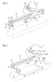
- FIG. 1 a device for detecting deformations of a rotor blade 3 of a wind turbine is shown, wherein in the FIGS. 1 to 4 only a cuboid cutout of the rotor blade 3 is shown.
- the corresponding rotor blade 3 is in the presented embodiment part of a wind turbine with a horizontal axis, which has a total of three rotor blades 3 in particular.
- the relevant device for detecting deformations of the rotor blade 3 comprises a position-measuring device 1, here an angle-measuring device, and an arm 2.
- the position measuring device 1 shown comprises a first component group 1.1 and a second component group 1.2.
- the first component group 1.1 has a shaft 1.11 with a shoulder ( FIG. 4 ), on which a material measure 1.14, z. B. by gluing, fixed and only with slight tolerance deviations is centered with respect to an axis A.
- the axis A extends in the y direction.
- the material measure 1.14 consists in the presented embodiment of glass and is designed annular. It naturally has two end surfaces, wherein on one of the end faces an angle scaling is applied.
- the angle scaling can be configured, for example, as an incremental graduation with radially oriented graduated lines, but additionally or alternatively, an absolute code can also be provided.
- a driver 1.12 On the shaft 1.11 a driver 1.12 is secured against rotation by clamping, so that upon movement of the driver 1.12 a pivotal movement of the shaft 1.11 can be generated.
- the driver 1.12 can be assigned to the first component group 1.1.
- a component 1.13 is precisely defined, which serves as a solid-body joint and is designed to be bendable.
- the component 1.13 can be designed as a thin-walled steel plate.
- the shaft 1.11 is in accordance with FIG. 4 within a body 1.25, which is assigned to the second component group 1.2, rotatably supported by two bearings 1.3.
- a light source not shown in the figures, which comprises, for example, an LED and a collimator lens, so that collimated light is emitted by the light source.
- This light passes through the material measure 1.14 or its angle scaling and is modulated according to the angular position between the first component group 1.1 and the second component group 1.2 or the shaft 1.11 and the body 1.25.
- the modulated light is scanned by a scanner 1.26, which is attached to the body 1.25.
- Corresponding photosensitive or photosensitive detectors are located on the sampled printed circuit board 1.26.
- the scanning 1.26 includes electronic components for signal shaping - for example, for amplification and digitization - of the scanning signals supplied by the detectors.
- a housing 1.21 is mounted around the scanning device 1.26 so that inter alia the light source, the measuring scale 1.14 and the scanning device 1.26 are protected against environmental influences.
- a holder 1.22 is attached on the body 1.25 .
- This holder 1.22 has a second adhesive surface 1.225 (see FIG. 1 ) for permanent bonding of the holder 1.22 with the rotor blade 3.
- 1.221 first mounting elements are attached to the holder 1.22.
- the first mounting elements 1.221 are designed as Velcro elements and with the aid of an adhesive layer 1.223 (FIG. FIG. 5 ) firmly connected to the holder 1.22.
- first mounting element 1.221 a second mounting element 1.222 is releasably attached.
- the second mounting elements 1.222 are also designed as Velcro elements, so that the first mounting elements are 1.221 with the second mounting elements 1.222 joined together by a Velcro connection.
- the second mounting elements 1.222 have an adhesive layer K on the surfaces facing away from the first mounting elements 1.221 on. When transporting the device for detecting deformations of a rotor blade 3 protective films are arranged on these surfaces to protect the adhesive layer.
- connection cable (not shown in the figures) which is connected to a socket 1.24, so that electrical signals and electrical energy can be transmitted between the subsequent electronics and the position-measuring device 1.
- the position-measuring device 1 By means of the position-measuring device 1, therefore, the relative angular position between the first component group 1.1 and the second component group 1.2 or between the shaft 1.11 and the body 1.25 can be determined.
- Such position measuring devices 1 are also often referred to as rotary encoders.
- the device for detecting deformations comprises the arm 2.
- This is made in the presented embodiment of glass fiber reinforced plastic and has a first adhesive surface 2.5 (see FIG. 1 ) and a second connection point 2.6.
- the second connection point 2.6 is in the exemplary embodiment a stop surface to which the component is 1.13, for example, by screw, mounted.
- the first adhesive surface 2.5 of the arm 2 is designed for permanently bonding the arm 2 to the rotor blade 3. Furthermore, the first 2 mounting elements 2.1 are attached to the arm. In the illustrated embodiment, the first mounting elements 2.1 are designed as Velcro elements. With the aid of an adhesive layer (analogous to the attachment of the first mounting elements 1.221 on the holder 1.22) and the first mounting elements 2.1 of the arm 2 with the arm 2 are firmly connected.
- a second mounting member 2.2 of the arm 2 is releasably secured respectively.
- the second mounting elements 2.2 of the arm 2 are also designed as Velcro elements, so that the first mounting elements 2.1 are joined together with the second mounting elements 2.2 each by a Velcro connection.
- the second mounting elements 2.2 of the arm 2 have an adhesive layer K on the surfaces facing away from the first mounting elements 2.1. When transporting the device for detecting deformations of a rotor blade 3 protective films are arranged on these surfaces to protect the adhesive layer.
- the rotor blade 3 is like the arm 2 made of glass fiber reinforced plastic.
- the device is then removed from the rotor blade 3 in such a way that the second mounting elements 1.222, 2.2 stick to the surface of the rotor blade 3, while the second mounting elements 1.222, 2.2 are separated from the first mounting elements 1.221, 2.1.
- the Velcro connections between the second mounting elements 1.222, 2.2 and the first mounting elements 1.221, 2.1 are thus solved in the presented embodiment.
- the holding forces, which are generated by the adhesive layers K are so large that a release or removal of the Velcro connection without detachment of the second mounting elements 1.222, 2.2 from the rotor blade 3 is possible.
- the device for detecting deformations is held by the holding forces of the mounting elements 1.222, 2.2, here by the Velcro connections, even when the device is mounted overhead.
- the adhesive in the adhesive layers 4, 5 can cure without further action by the installer. Further actions are no longer required after this assembly step, especially before hardening of the adhesive layers 4, 5 immovable connections between the holder 1.22 and the rotor blade 3 and between the arm 2 and the rotor blade 3 after the first and second mounting elements 2.1, 1.221, 2.2 , 1.222.
- the holder 1.22, the adhesive layers 1.223, the first and second mounting elements 1.221, 1.222 including the adhesive layers K are dimensioned so that an exact predetermined thickness Z of the adhesive layers 4 is formed after joining the first and second mounting members 1.221, 1.222 (see FIG FIG. 5 ).
- the same situation applies to the design of the arm 2 with its first and second mounting elements 2.1, 2.2 with respect to the adhesive layer 5.
- an exact thickness Z of the adhesive layers 4, 5 achievable independently of the invention in a simple manner reproducible by the invention present mounting position of the device.
- the arm 2 After assembly, the arm 2 is oriented in such a way that it runs in the x-direction, the x-direction essentially being along the longitudinal axis ⁇ (FIG. FIG. 6 ) of the rotor blade 3 corresponds.
- the first connection point of the arm 2 in this case the first adhesive surface 2.5, is arranged at a distance X from the second adhesive surface 1225 of the second component group 1.2, wherein the distance X is oriented orthogonal to the axis A.
- the arm 2 is relative to the axis A at a radial distance R mechanically, in particular articulated, coupled to the position measuring device 1.
- a Variation of the distance X for example, by a strain or by a contraction of the rotor blade 3, a relative pivotal movement between the first and the second component group 1.1, 1.2 are generated.
- the component 1.13 Due to the configuration of the component 1.13 as a thin-walled steel plate bending moments in the device can be reduced without affecting the measurement accuracy unfavorable.
- the component 1.13 is dimensioned so that its bending softness is matched with the required rotational or modulus of the position measuring device.
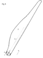
- the deformation of the rotor blade 3 in all dimensions, it is advantageous if several, eg four, such devices for detecting deformations in the root of the rotor blade 3 are mounted, as in FIG. 6 shown.
- the four devices for detecting deformations are arranged, preferably in the four main bending directions, offset by the circumference of the root of a rotor blade 3 in each case by 90 °.
- the rotor blades 3 are deformed by their own weight and by aerodynamic loads. In particular, the loads lead to expansions or compressions of the rotor blade 3 in the x direction. Accordingly, the distance between the second adhesive surface 1.225 and the first adhesive surface 2.5 changes. If the distance X is about 500 mm, the distance between the first and second adhesive surface 2.5, 1.225 changes at normal loads by about 0.5 mm. at a dimensioning of R with about 30 mm, this leads to a pivoting movement between the first component group 1.1 and the second component group 1.2 of about 1 °.
- the position measuring device 1 described above which operates on a precise optical principle, for example, has a resolution of 25 bits for one revolution (360 °), this corresponds to said geometric boundary conditions of a resolution of 5.6 nm based on the changes in length of the distance X between the first adhesive surface 2.5 and the second adhesive surface 1.225.
- the device for detecting deformations of a rotor blade 3 is naturally exposed to large temperature fluctuations in a wind turbine. Nevertheless, the above described device for detecting deformations can achieve extremely high measuring accuracies even under these adverse environmental conditions. This is due, on the one hand, to the fact that the thermal expansion of material measure 1.14 hardly plays a role through the detection of angular positions (the distances between the scale lines and their width vary with the temperature, but not the angular position). On the other hand, the arm 2 and the rotor blade 3 are made of the same material, so that both have the same thermal expansion behavior. Finally, by the pot-shaped electrically conductive housing 1.21 optimal protection, especially for the scanner 1.26 and associated electronics, against overvoltages z. B. be guaranteed during thunderstorms.
- the signals that can be output via the socket 1.24 are advantageously fully digital, so that the above-mentioned subsequent electronics can process the signals of all devices for detecting deformations of the rotor blades without further digitization. On the one hand, this ensures a signal transmission which is secure against external disturbances, on the other hand, the signals can be processed comparatively easily, so that the measured deformations can be processed in a closed-loop control circuit, z. B., for (separate) control of the pitch angle for each rotor blade 3 can be used.
Landscapes
- Engineering & Computer Science (AREA)
- Physics & Mathematics (AREA)
- General Physics & Mathematics (AREA)
- Mechanical Engineering (AREA)
- Life Sciences & Earth Sciences (AREA)
- Sustainable Development (AREA)
- Sustainable Energy (AREA)
- Chemical & Material Sciences (AREA)
- Combustion & Propulsion (AREA)
- General Engineering & Computer Science (AREA)
- Aviation & Aerospace Engineering (AREA)
- Wind Motors (AREA)
- Length Measuring Devices With Unspecified Measuring Means (AREA)
Abstract
Description
- Die Erfindung betrifft eine Vorrichtung zur Erfassung von Verformungen eines Rotorblatts einer Windkraftanlage gemäß dem Patentanspruch 1 sowie ein entsprechend ausgestaltetes Verfahren zur Montage einer derartigen Vorrichtung gemäß dem Patentanspruch 8.
- Rotorblätter von Windkraftanlagen sind verschiedensten Kräften ausgesetzt, die naturgemäß zu Verformungen der Rotorblätter führen und diese gegebenenfalls zu Schwingungen anregen. Schon alleine die Gewichtskraft eines umlaufenden Rotorblattes erzeugt eine periodische Verformung des betreffenden Rotorblattes. Diese Verformungen werden überlagert durch weitere Verformungen, die unter anderem aus den aerodynamischen Lasten resultieren. Beispielsweise hängen die aerodynamische Lasten vom Höhenprofil der Windgeschwindigkeit in Kombination mit Windböen oder Windturbulenzen ab. Ebenso wird bei jedem Umlauf durch den Turmvorstau eine pulsierende Kraft in das Rotorblatt eingeleitet. Das Ausmaß der Verformungen von Rotorblättern einer Windenergieanlage ist jedenfalls nur schwer voraussagbar, weshalb Anstrengungen unternommen werden, diese als Ist-Werte zu erfassen.
- Im Hinblick auf die Vorhersage von Ermüdungsschäden kann es vorteilhaft sein auf Basis der gemessenen Verformungen beziehungsweise Belastungen eine Information rückschauend über eine akkumulierte Belastung des Rotorblatts zu einem gewünschten Zeitpunkt zu erzeugen. Die Verfügbarkeit von derartigen Belastungswerten ist also im Hinblick auf kurzzeitige maximale Belastungen oder zu erwartende Ermüdungsschäden von Bedeutung. Außerdem kann in Kenntnis der Ist-Verformungen beziehungsweise Ist-Lasten die Regelung der Windkraftanlage optimiert werden, beispielsweise durch Verstellung der Pitch-Winkel.
- Aus der
DE 19847982 A1 ist eine Vorrichtung zur Erfassung von Schwingungen eines Rotorblattes einer Windkraftanlage bekannt, durch die unter Nutzung eines Abstandssensors als Linearelement eine Verformung des Rotorblattes festgestellt werden. Elemente der Vorrichtung werden mit Hilfe einer Klebefuge an einer Blattwandung befestigt. In der oben genannten Offenlegungsschrift wird einleitend darauf hingewiesen, dass Klebstellen handwerklich nur sehr aufwändig an bestehenden Rotorblättern nachzurüsten sind. - Der Erfindung liegt die Aufgabe zugrunde, eine Vorrichtung zur Erfassung von Verformungen eines Rotorblatts einer Windkraftanlage zu schaffen, welche vergleichsweise einfach und präzise am Rotorblatt montiert werden kann, insbesondere auch bei beengten Platzverhältnissen und schwierigen Montagelagen.
- Weiterhin wird durch die Erfindung ein Verfahren zur einfachen und präzisen Montage einer derartigen Vorrichtung an einem Rotorblatt geschaffen.
- Diese Aufgabe wird erfindungsgemäß durch die Vorrichtung mit den Merkmalen des Patentanspruchs 1 beziehungsweise durch ein Verfahren mit den Merkmalen des Patentanspruchs 8 gelöst.
- Demnach umfasst die Vorrichtung zur Erfassung von Verformungen eines Rotorblatts einer Windkraftanlage eine Positionsmesseinrichtung, welche eine erste und eine zweite Bauteilgruppe aufweist, sowie einen Arm. Die erste Bauteilgruppe der Positionsmesseinrichtung ist relativ zur zweiten Bauteilgruppe bewegbar beziehungsweise um eine Achse schwenkbar angeordnet, wobei durch die Positionsmesseinrichtung die relative Position zwischen der ersten und der zweiten Bauteilgruppe messbar ist. Der Arm ist mechanisch mit der ersten Bauteilgruppe gekoppelt und weist eine erste Klebefläche auf, die derart ausgestaltet ist, dass der Arm an dieser ersten Klebefläche dauerhaft mit dem Rotorblatt verbindbar beziehungsweise verklebbar ist. Die zweite Bauteilgruppe weist eine zweite Klebefläche auf, die so ausgestaltet ist, dass die zweite Bauteilgruppe mit dem Rotorblatt dauerhaft verbindbar beziehungsweise verklebbar ist. An der zweiten Bauteilgruppe und / oder am Arm ist ein erstes Montageelement fixiert. Die Vorrichtung zur Erfassung von Verformungen eines Rotorblatts weist weiterhin ein zweites Montageelement auf, wobei das erste Montageelement lösbar mit dem zweiten Montageelement verbunden werden kann und das zweite Montageelement so ausgestaltet ist, dass dieses am Rotorblatt haftend befestigbar ist.
- Die Vorrichtung zur Erfassung von Verformungen eines Rotorblatts umfasst also mindestens ein Paar von Montagelementen, welches das erste Montageelement und das zweite Montageelement umfasst. Zum Lösen des einen Paars oder wenn die Vorrichtung mehrere Paare von Montagelementen aufweist, zum Lösen der mehreren Paare, ist naturgemäß eine bestimmte Kraft erforderlich. Die Montagelemente sind mit Vorteil so ausgebildet, dass die Kraft zum Lösen größer ist als die Gewichtskraft der Vorrichtung zur Erfassung von Verformungen eines Rotorblatts. Auf diese Weise kann ohne weitere Hilfsmittel eine Über-Kopf-Montage der Vorrichtung am Rotorblatt vorgenommen werden.
- In weiterer Ausgestaltung der Erfindung weist das zweite Montageelement eine Klebeschicht auf, so dass mit Hilfe der Klebeschicht das zweite Montageelement am Rotorblatt haftend befestigbar ist. Auch die durch die Klebeschicht beziehungsweise bei Vorliegen von mehreren Klebeschichten durch die Klebeschichten erzeugte haftende Kraft ist mit Vorteil größer als die Gewichtskraft der Vorrichtung zur Erfassung von Verformungen eines Rotorblatts.
- Gemäß einer Weiterbildung der Erfindung ist das erste Montageelement durch einen Klettmechanismus lösbar mit dem zweiten Montageelement verbindbar. Demnach sind die Montageelemente als Klettelemente ausgestaltet, wobei die zusammenwirkenden ersten und zweiten Montageelemente Pilzkopfelemente oder Haken und Schlaufen aufweisen können. Alternativ können die Montageelemente eine Kombination aus Pilzkopfelementen und Schlaufenelementen aufweisen.
- Mit Vorteil ist die erste Bauteilgruppe relativ zur zweiten Bauteilgruppe um eine Achse schwenkbar angeordnet. Durch die Positionsmesseinrichtung, die in diesem Fall auch als Winkelmesseinrichtung bezeichnet werden kann, ist dann die relative Winkellage zwischen der ersten und der zweiten Bauteilgruppe messbar. Die erste Klebefläche ist in einem Abstand zur zweiten Klebefläche angeordnet. Der Arm ist in radialem Abstand bezogen auf die Achse mechanisch mit der ersten Bauteilgruppe gekoppelt, so dass bei Veränderung des Abstands eine relative Schwenkbewegung zwischen der ersten und der zweiten Bauteilgruppe erzeugbar ist.
- Auch wenn eine Verbindungslinie zwischen der ersten Klebefläche und der zweiten Klebefläche nicht streng orthogonal zur Achse verläuft, so ist dennoch ein Abstand orthogonal zur Achse feststellbar, sofern die Verbindungslinie zwischen der ersten und der zweiten Klebefläche nicht genau parallel zur Achse verläuft. Demgemäß ist unter der Formulierung, wonach der Abstand orthogonal zur Achse ist, zu verstehen, dass eine Verbindungslinie zwischen der ersten und der zweiten Klebefläche eine Richtungskomponente (entsprechend dem Abstand senkrecht zur Achsrichtung) aufweist, die orthogonal zur Achse orientiert ist.
- Mit Vorteil ist der Arm aus einem Material hergestellt, welches Kunststoff umfasst. Der Kunststoff kann insbesondere faserverstärkt sein, z. B. durch Glas- und / oder Kohlefasern.
- In weiterer Ausgestaltung der Erfindung ist die erste Bauteilgruppe gelenkig mit dem Arm verbunden, insbesondere über ein biegeweiches Bauelement, welches als Festkörpergelenk beziehungsweise als ein einstückiges Gelenk ausgestaltet sein kann.
- Mit Vorteil weist die Positionsmesseinrichtung ein Wälzlager oder mehrere Wälzlager zur schwenkbaren Lagerung der ersten Bauteilgruppe relativ zur zweiten Bauteilgruppe auf. Eine derartige Lagerung dient dann auch zur Führung des Arms. Alternativ kann auch ein Gleitlager oder ein Festköpergelenk zur schwenkbaren Lagerung der ersten Bauteilgruppe relativ zur zweiten Bauteilgruppe verwendet werden.
- Gemäß einer Weiterbildung der Erfindung weist die Positionsmesseinrichtung eine Maßverkörperung und ein Element zur Abtastung der Maßverkörperung auf. Die Maßverkörperung kann ringförmig ausgestaltet sein und ist dann geometrisch betrachtet ein Hohlzylinder mit umlaufenden Mantelseiten. Die Mantelseiten können eine geringe Höhe aufweisen, so dass die Maßverkörperung als Ringscheibe ausgestaltet ist mit ringförmigen parallel zueinander ausgerichteten Stirnflächen, die auch als Grund- oder Deckflächen bezeichnet werden können. Die Winkelskalierung oder Winkelcodierung kann auf einer der Stirnflächen aufgebracht sein.
- Gerade wenn die Maßverkörperung so ausgestaltet ist, dass die Mantelseiten eine vergleichsweise größere Höhe aufweist, also bei einer eher trommelförmigen Maßverkörperung, kann die Winkelskalierung auf der Mantelseite aufgebracht sein. Die Maßverkörperung kann aber auch als Maßband ausgestaltet sein, welches beispielsweise an der Mantelseite eines zylindrischen Körpers an dessen Außenseite oder an dessen Innenseite befestigt wird.
- Zudem kann die Maßverkörperung so ausgestaltet sein, dass diese nur über einen begrenzten Winkelbereich eine Skalierung aufweist, sich also nicht über 360° erstreckt, sondern nur ein Winkelsegment als Messbereich aufweist. Die winkelmäßige Erstreckung der Maßverkörperung kann auf den maximalen Messbereich beziehungsweise Schwenkwinkel abgestimmt sein.
- Alternativ kann die Positionsmesseinrichtung eine Maßverkörperung und ein Element zur Abtastung der Maßverkörperung aufweisen, die dazu ausgebildet sind eine lineare Verschiebung zueinander zu messen. Die Maßverkörperung kann demnach linear ausgestaltet sein und an dem Arm befestigt oder direkt auf diesem aufgebracht sein.
- Mit Vorteil ist das Element zur Abtastung der Maßverkörperung photosensitiv beziehungsweise lichtempfindlich ausgestaltet. Demgemäß beruht also eine derartige Abtastung auf einem optischen Prinzip.
- Alternativ kann die Abtastung auf einem induktiven oder magnetischen Prinzip beruhen.
- Die Positionsmesseinrichtung kann insbesondere digitale Positionssignale und / oder Signale, die durch ein- oder mehrmaliges differenzieren der Positionssignale nach der Zeit erzeugt worden sind, liefern. Die Übertragung der betreffenden Signale kann rein digital und seriell erfolgen, so dass eine vergleichsweise einfache Verarbeitung der Signale möglich ist, z. B. zur Einbindung in eine hochdynamische Regelung.
- Die Positionsmesseinrichtung weist mit Vorteil eine Maßverkörperung mit einer absoluten Codierung auf, so dass durch die Positionsmesseinrichtung die relative Position (Winkellage oder lineare Verschiebung) zwischen der ersten und der zweiten Bauteilgruppe als eine absolute Größe messbar ist (im Gegensatz zu einer inkrementalen Messung). Auf diese Weise kann zu beliebigen Zeitpunkten die absolute Verformung des Rotorblatts gemessen werden. Dies ist insbesondere zur Überprüfung von Setzungsvorgängen in der Struktur des Rotorblatts vorteilhaft. Für eine derartige Überprüfung wird das betreffende Rotorblatt außerhalb des eigentlichen Betriebs in eine waagrechte Stellung gefahren. Danach wird die Verformung in dieser Position gemessen. Wenn nun eine absolut arbeitende Positionsmesseinrichtung verwendet wird, kann der absolute Messwert direkt mit vorhergegangenen (ebenfalls absoluten) Messungen verglichen werden.
- Ein weiterer Aspekt der Erfindung betrifft ein Rotorblatt einer Windkraftanlage mit einer Vorrichtung zur Erfassung von Verformungen. Diese Vorrichtung umfasst ihrerseits eine Positionsmesseinrichtung, welche eine erste und eine zweite Bauteilgruppe aufweist, und einen Arm. Die erste Bauteilgruppe der Positionsmesseinrichtung ist relativ zur zweiten Bauteilgruppe bewegbar beziehungsweise um eine Achse schwenkbar angeordnet, wobei durch die Positionsmesseinrichtung die relative Position zwischen der ersten und der zweiten Bauteilgruppe messbar ist. Der Arm ist mechanisch mit der ersten Bauteilgruppe gekoppelt und weist eine erste Klebefläche auf, wobei der Arm an dieser ersten Klebefläche dauerhaft mit dem Rotorblatt verbunden ist. Die zweite Bauteilgruppe weist eine zweite Klebefläche auf, durch welche die zweite Bauteilgruppe mit dem Rotorblatt dauerhaft verbunden ist. An der zweiten Bauteilgruppe und / oder am Arm ist ein erstes Montageelement fixiert. Die Vorrichtung zur Erfassung von Verformungen eines Rotorblatts weist weiterhin ein zweites Montageelement auf, wobei das erste Montageelement lösbar mit dem zweiten Montageelement verbunden werden kann und das zweite Montageelement so ausgestaltet ist, dass dieses am Rotorblatt haftend befestigt ist.
- In weiterer Ausgestaltung des Rotorblatts weist das Rotorblatt mehrere Vorrichtungen zur Erfassung von Verformungen auf.
- Mit Vorteil ist der Arm in Längsrichtung des Rotorblatts orientiert, wobei das Rotorblatt (zumindest im Bereich seiner Wurzel) eine zentrale sich in Längsrichtung erstreckende Längsachse aufweist.
- Sofern die Positionsmesseinrichtung als Winkelmesseinrichtung ausgestaltet ist, kann die (Schwenk-) Achse der Positionsmesseinrichtung im Wesentlichen orthogonal zur Längsrichtung des Rotorblatts ausgerichtet sein. Dabei kann die Positionsmesseinrichtung so angeordnet sein, dass die Achse im Wesentlichen parallel zur Innenwand des Rotorblatts orientiert ist, oder so angeordnet sein, dass die Achse im Wesentlichen orthogonal zur Innenwand des Rotorblatts orientiert ist. Demnach ist der Arm in Längsrichtung des Rotorblatts orientiert und die (Schwenk-) Achse der Positionsmesseinrichtung ist relativ zur Längsachse des Rotorblatts tangential oder radial ausgerichtet. Die tangentiale oder radiale Ausrichtung bezieht sich insbesondere auf einen Kreisbogen, dessen Mittelpunkt auf der Längsachse des Rotorblatts zu liegen kommt.
- Weiterhin kann die Vorrichtung zur Erfassung von Verformungen an der Wurzel des Rotorblatts montiert sein, also in der Nähe des Rotorblattanschlusses an der Nabe der Windkraftanlage. Somit kann die zweite Bauteilgruppe im Bereich des Blattanschlusses an einer Nabe befestigt werden.
- In weiterer Ausgestaltung der Erfindung weist der Arm beziehungsweise das Material, aus dem dieser hergestellt ist, den gleichen Wärmeausdehnungskoeffizienten auf wie das Rotorblatt beziehungsweise dessen Material.
- Mit Vorteil weist das Rotorblatt mehrere Vorrichtungen zur Erfassung von Verformungen auf. Durch die so erzeugten Signale der einzelnen Vorrichtungen kann nach der Verknüpfung beziehungsweise Verrechnung der jeweiligen Signale eine räumliche Verformung des Rotorblatts bestimmt werden.
- Die Erfindung betrifft ein Verfahren zur Montage einer Vorrichtung zur Erfassung von Verformungen eines Rotorblatts einer Windkraftanlage. Das Verfahren zur Montage der beschriebenen Vorrichtung umfasst folgende Schritte:
- Befestigen des zweiten Montageelements an dem Rotorblatt,
- Aufbringen eines Klebers auf die erste und die zweite Klebefläche,
- Befestigen der Vorrichtung am Rotorblatt durch Zusammenfügen des ersten Montageelements mit dem zweiten Montageelement, wobei der Kleber sowohl mit der ersten und der zweiten Klebefläche in Kontakt ist als auch mit dem Rotorblatt.
- Mit Vorteil weist das zweite Montageelement eine Klebeschicht auf, so dass dieses am Rotorblatt haftend befestigbar ist. Das zweite Montageelement ist lösbar vor dem Befestigen des zweiten Montageelements an dem Rotorblatt mit dem ersten Montageelement verbunden. Vor dem Aufbringen des Klebers
- wird die Vorrichtung an das Rotorblatt gedrückt, so dass das zweite Montageelement am Rotorblatt mit Hilfe der Klebeschicht haftet,
- wird die Vorrichtung zum darauffolgenden Aufbringen des Klebers wieder vom Rotorblatt entfernt.
- Nach dem Aufbringen des Klebers wird die Vorrichtung am Rotorblatt durch Zusammenfügen des ersten Montageelements mit dem zweiten Montageelement wieder befestigt, wobei der Kleber sowohl mit der ersten und der zweiten Klebefläche als auch mit dem Rotorblatt in Kontakt ist. Die Vorrichtung ist dadurch so ausgestaltet, dass sich stets reproduzierbar eine vorgegebene Dicke der Schicht des Klebers einstellt.
- Weitere vorteilhafte Ausgestaltungen der Erfindung sind den abhängigen Ansprüchen zu entnehmen.
- Weitere Merkmale und Vorteile der Erfindung werden bei der nachfolgenden Beschreibung eines Ausführungsbeispiels anhand der Figuren deutlich werden.
-
- Figur 1
- eine perspektivische Ansicht der Vorrichtung zur Erfassung von Verformungen eines Rotorblatts in einer ersten Montagephase,
- Figur 2
- eine perspektivische Ansicht der Vorrichtung zur Erfassung von Verformungen eines Rotorblatts in einer zweiten Montagephase,
- Figur 3
- eine perspektivische Ansicht der Vorrichtung zur Erfassung von Verformungen eines Rotorblatts in einer dritten Montagephase,
- Figur 4
- eine Schnittansicht der Vorrichtung zur Erfassung von Verformungen eines Rotorblatts,
- Figur 5
- eine Seitenansicht eines Details der Vorrichtung,
- Figur 6
- eine schematische Ansicht eines Rotorblatts mit Vorrichtungen zur Erfassung von Verformungen.
- In der
Figur 1 ist eine Vorrichtung zur Erfassung von Verformungen eines Rotorblatts 3 einer Windkraftanlage gezeigt, wobei in denFiguren 1 bis 4 nur ein quaderförmiger Ausschnitt des Rotorblatts 3 dargestellt ist. Das entsprechende Rotorblatt 3 ist im vorgestellten Ausführungsbeispiel Bestandteil einer Windkraftanlage mit horizontaler Achse, die insbesondere insgesamt drei Rotorblätter 3 aufweist. Die betreffende Vorrichtung zur Erfassung von Verformungen des Rotorblatts 3 umfasst eine Positionsmesseinrichtung 1, hier eine Winkelmesseinrichtung, und einen Arm 2. - Die gezeigte Positionsmesseinrichtung 1 umfasst eine erste Bauteilgruppe 1.1 und eine zweite Bauteilgruppe 1.2. Die erste Bauteilgruppe 1.1 weist eine Welle 1.11 mit einem Absatz auf (
Figur 4 ), an dem eine Maßverkörperung 1.14, z. B. durch eine Klebung, fest und nur mit geringen Toleranzabweichungen zentrisch bezüglich einer Achse A verbunden ist. Die Achse A erstreckt sich in y-Richtung. Die Maßverkörperung 1.14 besteht im vorgestellten Ausführungsbeispiel aus Glas und ist ringförmig ausgestaltet. Sie weist naturgemäß zwei Stirnflächen auf, wobei auf einer der Stirnflächen eine Winkelskalierung aufgebracht ist. Die Winkelskalierung kann beispielsweise als eine inkrementale Teilung mit radial orientierten Skalenstrichen ausgestaltet sein, wobei jedoch zusätzlich oder alternativ auch ein absoluter Code vorgesehen sein kann. - An der Welle 1.11 ist ein Mitnehmer 1.12 klemmend verdrehsicher befestigt, so dass bei Bewegung des Mitnehmers 1.12 eine Schwenkbewegung der Welle 1.11 erzeugt werden kann. Der Mitnehmer 1.12 kann der ersten Bauteilgruppe 1.1 zugeordnet werden. Am Mitnehmer 1.12 ist ein Bauelement 1.13 präzise festgelegt, welches als Festkörpergelenk dient und entsprechend biegeweich ausgestaltet ist. Insbesondere kann das Bauelement 1.13 als ein dünnwandiges Stahlplättchen ausgestaltet sein.
- Die Welle 1.11 ist gemäß der
Figur 4 innerhalb eines Körpers 1.25, welcher der zweiten Bauteilgruppe 1.2 zuzuordnen ist, durch zwei Wälzlager 1.3 drehbar gelagert. Weiterhin der zweiten Bauteilgruppe 1.2 zuzuordnen ist eine in den Figuren nicht dargestellte Lichtquelle, die beispielsweise eine LED und eine Kollimatorlinse umfasst, so dass durch die Lichtquelle kollimiertes Licht emittiert wird. Dieses Licht tritt durch die Maßverkörperung 1.14 bzw. deren Winkelskalierung hindurch und wird entsprechend der Winkelstellung zwischen der ersten Bauteilgruppe 1.1 und der zweiten Bauteilgruppe 1.2 beziehungsweise der Welle 1.11 und dem Körper 1.25 moduliert. Das modulierte Licht wird von einer Abtasteinrichtung 1.26, welche am Körper 1.25 befestigt ist, abgetastet. Entsprechende lichtempfindliche beziehungsweise photosensitive Detektoren befinden sich auf der als bestückte Leiterplatte ausgestalteten Abtasteinrichtung 1.26. Unter anderem umfasst die Abtasteinrichtung 1.26 auch elektronische Bauelemente zur Signalformung - beispielsweise zur Verstärkung und Digitalisierung - der von den Detektoren gelieferten Abtastsignale. - Um die Abtasteinrichtung 1.26 herum ist ein Gehäuse 1.21 montiert, so dass unter anderem die Lichtquelle, die Maßverkörperung 1.14 und die Abtasteinrichtung 1.26 gegenüber Umwelteinflüssen geschützt sind. Am Körper 1.25 ist ein Halter 1.22 befestigt. Dieser Halter 1.22 weist eine zweite Klebefläche 1.225 auf (siehe
Figur 1 ) zum dauerhaften verkleben des Halters 1.22 mit dem Rotorblatt 3. Zudem sind am Halter 1.22 erste Montageelemente 1.221 befestigt. Im vorgestellten Ausführungsbeispiel sind die ersten Montageelemente 1.221 als Klettelemente ausgestaltet und mit Hilfe einer Kleberschicht 1.223 (Figur 5 ) mit dem Halter 1.22 fest verbunden. - An jeweils einem ersten Montageelement 1.221 ist jeweils ein zweites Montageelement 1.222 lösbar befestigt. Im vorgestellten Ausführungsbeispiel sind die zweiten Montageelemente 1.222 ebenfalls als Klettelemente ausgestaltet, so dass die ersten Montageelemente 1.221 mit den zweiten Montageelementen 1.222 jeweils durch eine Klettverbindung zusammengefügt sind. Die zweiten Montageelemente 1.222 weisen an den von den ersten Montageelementen 1.221 abgewandten Oberflächen eine Kleberschicht K auf. Beim Transport der Vorrichtung zur Erfassung von Verformungen eines Rotorblatts 3 sind auf diesen Oberflächen zum Schutz der Kleberschicht K Schutzfolien angeordnet.
- Über ein in den Figuren nicht gezeigtes Anschlusskabel, welches an einer Buchse 1.24 angeschlossen wird, wird eine elektrische Verbindung zwischen der Positionsmesseinrichtung 1 und einer Folgeelektronik hergestellt, so dass elektrische Signale und elektrische Energie zwischen der Folgeelektronik und der Positionsmesseinrichtung 1 übertragen werden können.
- Durch die Positionsmesseinrichtung 1 kann also die relative Winkelstellung zwischen der ersten Bauteilgruppe 1.1 und der zweiten Bauteilgruppe 1.2 beziehungsweise zwischen der Welle 1.11 und dem Körper 1.25 bestimmt werden. Derartige Positionsmesseinrichtungen 1 werden auch häufig als Drehgeber bezeichnet.
- Neben der Positionsmesseinrichtung 1 umfasst die Vorrichtung zur Erfassung von Verformungen den Arm 2. Dieser ist im vorgestellten Ausführungsbeispiel aus glasfaserverstärktem Kunststoff hergestellt und weist eine erste Klebefläche 2.5 (siehe
Figur 1 ) und eine zweite Verbindungsstelle 2.6 auf. Die zweite Verbindungsstelle 2.6 ist im Ausführungsbeispiel eine Anschlagfläche, an die das Bauelement 1.13, beispielsweise durch Schraubverbindungen, montiert wird. - Die erste Klebefläche 2.5 des Arms 2 ist zum dauerhaften Verkleben des Arms 2 mit dem Rotorblatt 3 ausgebildet. Ferner sind am Arm 2 erste Montageelemente 2.1 befestigt. Im vorgestellten Ausführungsbeispiel sind die ersten Montageelemente 2.1 als Klettelemente ausgestaltet. Mit Hilfe einer Kleberschicht (analog zur Befestigung der ersten Montageelemente 1.221 am Halter 1.22) sind auch die ersten Montageelemente 2.1 des Arms 2 mit dem Arm 2 fest verbunden.
- An jeweils einem ersten Montageelement 2.1 des Arms 2 ist jeweils ein zweites Montageelement 2.2 des Arms 2 lösbar befestigt. Im vorgestellten Ausführungsbeispiel sind die zweiten Montageelemente 2.2 des Arms 2 ebenfalls als Klettelemente ausgestaltet, so dass die ersten Montageelemente 2.1 mit den zweiten Montageelementen 2.2 jeweils durch eine Klettverbindung zusammengefügt sind. Die zweiten Montageelemente 2.2 des Arms 2 weisen an den von den ersten Montageelementen 2.1 abgewandten Oberflächen eine Kleberschicht K auf. Beim Transport der Vorrichtung zur Erfassung von Verformungen eines Rotorblatts 3 sind auf diesen Oberflächen zum Schutz der Kleberschicht K Schutzfolien angeordnet.
- Das Rotorblatt 3 ist wie der Arm 2 aus glasfaserverstärktem Kunststoff hergestellt.
- Im Zuge der Montage der Vorrichtung zur Erfassung von Verformungen eines Rotorblatts 3 einer Windkraftanlage werden zunächst die Schutzfolien der zweiten Montageelemente 1.222, 2.2 abgezogen, so dass die mit der Kleberschicht K versehenen Oberflächen der zweiten Montageelemente 1.222, 2.2 freigelegt sind. Diese Montagephase ist in der
Figur 1 gezeigt. Dann wird die Vorrichtung auf die entsprechend vorbereitete Oberfläche an der Wurzel des Rotorblatts 3 aufgesetzt, so dass die zweiten Montageelemente 1.222, 2.2 an der Oberfläche des Rotorblatts 3 kleben. - Als nächstes wird dann die Vorrichtung vom Rotorblatt 3 in der Weise entfernt, dass die zweiten Montageelemente 1.222, 2.2 an der Oberfläche des Rotorblatts 3 kleben bleiben, während die zweiten Montageelemente 1.222, 2.2 von den ersten Montageelementen 1.221, 2.1 getrennt werden. Insbesondere werden demnach im vorgestellten Ausführungsbeispiel die Klettverbindungen zwischen den zweiten Montageelementen 1.222, 2.2 und den ersten Montageelementen 1.221, 2.1 gelöst. Die Haltekräfte, welche durch die Klebeschichten K erzeugt werden sind also so groß, dass ein Lösen beziehungsweise Abziehen der Klettverbindung ohne ein Ablösen der zweiten Montageelemente 1.222, 2.2 vom Rotorblatt 3 möglich ist.
- Nun kann die Vorrichtung, bestehend aus der Positionsmesseinrichtung 1 samt Halter 1.22 sowie dem Arm 2, abgelegt werden. Als nächstes wird auf die erste und die zweite Klebefläche 2.5, 1.225 (jeweils zwischen die ersten Montageelemente 1.221, 2.1) Kleber aufgetragen, hier ein ZweiKomponenten-Kleber, so dass Klebeschichten 4 und 5 entstehen. Um eine für die Messzwecke erforderliche Qualität der Klebung zu erreichen, ist es notwendig den Kleber ganzflächig und blasenfrei zu applizieren.
- Darauffolgend werden gemäß der
Figur 2 die ersten Montageelemente 1.221, 2.1 mit den zweiten Montageelementen 1.222, 2.2 verbunden, so dass die Vorrichtung zur Erfassung von Verformungen in einer endgültigen Lage relativ zum Rotorblatt 3 gebracht ist. Die Vorrichtung zur Erfassung von Verformungen wird durch die Haltekräfte der Montageelemente 1.222, 2.2, hier durch die Klettverbindungen, gehalten, auch wenn die Vorrichtung über-Kopf montiert wird. Der Kleber in den Klebeschichten 4, 5 kann ohne weiteres Zutun des Monteurs aushärten. Weitere Aktionen sind nach diesem Montageschritt nicht mehr erforderlich, zumal schon vor dem Aushärten der Klebeschichten 4, 5 unverschiebbare Verbindungen zwischen dem Halter 1.22 und dem Rotorblatt 3 sowie zwischen dem Arm 2 und dem Rotorblatt 3 nach der ersten und zweiten Montageelemente 2.1, 1.221, 2.2, 1.222 vorliegen. - Zudem sind der Halter 1.22, die Kleberschichten 1.223, die ersten und zweiten Montagelemente 1.221, 1.222 inklusive der Klebeschichten K so bemessen, dass eine exakte vorbestimmte Dicke Z der Klebeschichten 4 nach dem Zusammenfügen der ersten und zweiten Montagelemente 1.221, 1.222 hergestellt ist (siehe
Figur 5 ). Der gleiche Sachverhalt gilt auch für die Ausgestaltung des Arms 2 mit seinen ersten und zweiten Montageelementen 2.1, 2.2 im Hinblick auf die Klebeschicht 5. Somit ist durch die Erfindung auf einfache Weise reproduzierbar eine exakte Dicke Z der Klebeschichten 4, 5 erreichbar, unabhängig von der vorliegenden Montagelage der Vorrichtung. - Der Arm 2 ist nach erfolgter Montage so orientiert, dass dieser in x-Richtung verläuft, wobei die x-Richtung im Wesentlichen der Längsachse ξ (
Figur 6 ) des Rotorblatts 3 entspricht. Somit ist also die erste Verbindungsstelle des Arms 2, hier also die erste Klebefläche 2.5, in einem Abstand X zur zweiten Klebefläche 1.225 der zweiten Bauteilgruppe 1.2 angeordnet, wobei der Abstand X orthogonal zur Achse A orientiert ist. Der Arm 2 ist bezogen auf die Achse A in radialem Abstand R mechanisch, insbesondere gelenkig, mit der Positionsmesseinrichtung 1 gekoppelt. Auf diese Weise kann durch eine Veränderung des Abstandes X, beispielsweise durch eine Dehnung oder durch eine Kontraktion des Rotorblatts 3 eine relative Schwenkbewegung zwischen der ersten und der zweiten Bauteilgruppe 1.1, 1.2 erzeugt werden. - Durch die Ausgestaltung des Bauelements 1.13 als ein dünnwandiges Stahlplättchen können Biegemomente in der Vorrichtung reduziert werden, ohne die Messgenauigkeit ungünstig zu beeinflussen. Das Bauelement 1.13 ist so dimensioniert, dass dessen Biegeweichheit mit dem erforderlichen Dreh- beziehungsweise Widerstandsmoment der Positionsmesseinrichtung abgestimmt ist.
- Um eine Aussage über die Verformung des Rotorblatts 3 in allen Dimensionen treffen zu können ist es vorteilhaft, wenn mehrere , z.B. vier, derartige Vorrichtungen zur Erfassung von Verformungen in der Wurzel des Rotorblatts 3 montiert werden, wie in der
Figur 6 dargestellt. Die vier Vorrichtungen zur Erfassung von Verformungen sind, vorzugsweise in den vier Hauptbiegerichtungen, über den Umfang der Wurzel eines Rotorblatts 3 jeweils um 90° versetzt angeordnet. - Durch das erfindungsgemäße Verfahren und die Vorrichtung ist es möglich Rotorblätter mit einer Vorrichtung zur Erfassung von Verformungen auf einfache Weise nachzurüsten. Um die Verformungen verlässlich und genau bestimmen zu können, ist es wichtig, dass die Vorrichtungen sorgfältig am Rotorblatt 3 verklebt werden. Mit der Erfindung können entsprechende Vorrichtungen auch bei beengten Platzverhältnissen und schwierigen Montagelagen (bis zur Über-Kopf-Montage) vergleichsweise einfach präzise verklebt werden.
- Im Betrieb der Windkraftanlage werden die Rotorblätter 3 durch ihr Eigengewicht und durch aerodynamische Lasten verformt. Insbesondere führen die Lasten zu Dehnungen oder Stauchungen des Rotorblatts 3 in x-Richtung. Entsprechend verändert sich der Abstand zwischen der zweiten Klebefläche 1.225 und der ersten Klebefläche 2.5. Wenn der Abstand X etwa 500 mm beträgt, ändert sich der Abstand zwischen der ersten und zweiten Klebefläche 2.5, 1.225 bei üblichen Belastungen um etwa 0,5 mm. Bei einer Dimensionierung von R mit etwa 30 mm führt dies zu einer Schwenkbewegung zwischen der ersten Bauteilgruppe 1.1 und der zweiten Bauteilgruppe 1.2 von etwa 1°. Die oben beschriebene Positionsmesseinrichtung 1, die nach einem präzisen optischen Prinzip arbeitet, hat beispielsweise eine Auflösung von 25 Bit für eine Umdrehung (360°), dies entspricht mit den genannten geometrischen Randbedingungen einer Auflösung von 5,6 nm bezogen auf die Längenänderungen des Abstands X zwischen der ersten Klebefläche 2.5 und der zweiten Klebefläche 1.225.
- Die Vorrichtung zur Erfassung von Verformungen eines Rotorblatts 3 ist naturgemäß in einer Windkraftanlage großen Temperaturschwankungen ausgesetzt. Dennoch können durch die oben dargelegte Vorrichtung zur Erfassung von Verformungen überaus hohe Messgenauigkeiten auch unter diesen widrigen Umgebungsbedingungen erreicht werden. Dies liegt zum einen daran, dass durch die Erfassung von Winkellagen die thermische Ausdehnung der Maßverkörperung 1.14 kaum eine Rolle spielt (die Abstände zwischen den Skalierungsstrichen und deren Breite variieren mit der Temperatur, jedoch nicht die Winkellage). Zum anderen sind der Arm 2 und das Rotorblatt 3 aus dem gleichen Material hergestellt, so dass beide dasselbe thermische Ausdehnungsverhalten aufweisen. Schließlich kann durch das topfförmige elektrisch leitende Gehäuse 1.21 ein optimaler Schutz, insbesondere für die Abtasteinrichtung 1.26 und zugehöriger Elektronik, vor Überspannungen z. B. bei Gewittern gewährleistet werden.
- Die über die Buchse 1.24 abgebbaren Signale sind vorteilhafterweise voll digital, so dass die oben genannte Folgeelektronik die Signale sämtlicher Vorrichtungen zur Erfassung von Verformungen der Rotorblätter ohne weitere Digitalisierung verarbeiten kann. Dies gewährleistet einerseits eine gegenüber äußeren Störungen sichere Signalübertragung, zum anderen können die Signale vergleichsweise einfach verarbeitet werden, so dass die gemessenen Verformungen in einem Regelkreis, z. B., zur (separaten) Regelung des Pitch-Winkels für jedes Rotorblatt 3 verwendet werden können.
Claims (9)
- Vorrichtung zur Erfassung von Verformungen eines Rotorblatts (3) einer Windkraftanlage, umfassend- eine Positionsmesseinrichtung (1), welche eine erste und eine zweite Bauteilgruppe (1.1, 1.2) aufweist, wobei die erste Bauteilgruppe (1.1) relativ zur zweiten Bauteilgruppe (1.2) bewegbar angeordnet ist und durch die Positionsmesseinrichtung (1) die relative Position zwischen der ersten und der zweiten Bauteilgruppe (1.1, 1.2) messbar ist,- einen Arm (2), welcher mechanisch mit der ersten Bauteilgruppe (1.1) gekoppelt ist und eine erste Klebefläche (2.5) aufweist, die derart ausgestaltet ist, dass der Arm (2) an dieser mit dem Rotorblatt (3) dauerhaft verbindbar ist, wobeidie zweite Bauteilgruppe (1.2) eine zweite Klebefläche (1.225) aufweist, die so ausgestaltet ist, dass die zweite Bauteilgruppe (1.2) mit dem Rotorblatt (3) dauerhaft verbindbar ist, und
an der zweiten Bauteilgruppe (1.2) und / oder am Arm (2) ein erstes Montageelement (1.121, 2.1) fixiert ist, und
die Vorrichtung zur Erfassung von Verformungen eines Rotorblatts (3) weiterhin ein zweites Montageelement (1.122, 2.2) aufweist, wobei das erste Montageelement (1.121, 2.1) lösbar mit dem zweiten Montageelement (1.122, 2.2) verbindbar ist und das zweite Montageelement (1.122, 2.2) so ausgestaltet ist, dass dieses am Rotorblatt (3) haftend befestigbar ist. - Vorrichtung gemäß dem Anspruch 1, wobei das zweite Montageelement (1.122, 2.2) eine Klebeschicht (K) aufweist, so dass dieses am Rotorblatt (3) haftend befestigbar ist.
- Vorrichtung gemäß einem der vorhergehenden Ansprüche, wobei das erste Montageelement (1.121, 2.1) durch einen Klettmechanismus lösbar mit dem zweiten Montageelement (1.222, 2.2) verbindbar ist.
- Vorrichtung gemäß einem der vorhergehenden Ansprüche, wobei die erste Bauteilgruppe (1.1) relativ zur zweiten Bauteilgruppe (1.2) um eine Achse (A) schwenkbar angeordnet ist und durch die Positionsmesseinrichtung (1) die relative Winkellage zwischen der ersten und der zweiten Bauteilgruppe (1.1, 1.2) messbar ist und
die erste Klebefläche (2.5) in einem Abstand (X) zur zweiten Klebefläche (1.125) angeordnet ist,
der Arm (2) in radialem Abstand (R) mechanisch mit der ersten Bauteilgruppe (1.1) gekoppelt ist, so dass bei Veränderung des Abstands (X) eine relative Schwenkbewegung zwischen der ersten und der zweiten Bauteilgruppe (1.1, 1.2) erzeugbar ist. - Vorrichtung gemäß einem der vorhergehenden Ansprüche, wobei die erste Bauteilgruppe (1.1) gelenkig mit dem Arm (2), insbesondere über ein biegeweiches Bauelement (1.13), verbunden ist.
- Vorrichtung gemäß einem der vorhergehenden Ansprüche, wobei die Positionsmesseinrichtung (1) eine Maßverkörperung (1.14) und ein Element (1.26) zur Abtastung der Maßverkörperung (1.14) aufweist.
- Vorrichtung gemäß dem Anspruch 6, wobei das Element (1.26) zur Abtastung der Maßverkörperung (1.14) photosensitiv ist.
- Verfahren zur Montage einer Vorrichtung gemäß einem der vorhergehenden Ansprüche an dem Rotorblatt (3), mit folgenden Schritten,- Befestigen des zweiten Montageelements (1.222, 2.2) an dem Rotorblatt (3),- Aufbringen eines Klebers auf die erste und die zweite Klebefläche (1.225, 2.5),- Befestigen der Vorrichtung am Rotorblatt (3) durch Zusammenfügen des ersten Montageelements (1.221, 2.1) mit dem zweiten Montageelement (1.222, 2.2), wobei der Kleber sowohl mit der ersten und der zweiten Klebefläche (1.225, 2.5) in Kontakt ist als auch mit dem Rotorblatt (3).
- Verfahren gemäß dem Anspruch 8, wobei das zweite Montageelement (1.122, 2.2) eine Klebeschicht (K) aufweist, so dass dieses am Rotorblatt (3) haftend befestigbar ist und vor dem Befestigen des zweiten Montageelements (1.222, 2.2) an dem Rotorblatt (3) das zweite Montageelement (1.222, 2.2) lösbar mit dem erstem ersten Montageelement (1.221, 2.1) verbunden ist, wobei vor dem Aufbringen des Klebers- die Vorrichtung an das Rotorblatt (3) gedrückt wird, so dass das zweite Montageelement (1.122, 2.2) am Rotorblatt (3) haftet,- die Vorrichtung zum darauffolgenden Aufbringen des Klebers vom Rotorblatt (3) wieder entfernt wird.
Applications Claiming Priority (1)
| Application Number | Priority Date | Filing Date | Title |
|---|---|---|---|
| DE102014218518.1A DE102014218518A1 (de) | 2014-09-16 | 2014-09-16 | Vorrichtung zur Erfassung von Verformungen eines Rotorblatts und Verfahren zur Montage einer derartigen Vorrichtung |
Publications (2)
| Publication Number | Publication Date |
|---|---|
| EP2998717A1 true EP2998717A1 (de) | 2016-03-23 |
| EP2998717B1 EP2998717B1 (de) | 2017-08-09 |
Family
ID=53539478
Family Applications (1)
| Application Number | Title | Priority Date | Filing Date |
|---|---|---|---|
| EP15173116.3A Active EP2998717B1 (de) | 2014-09-16 | 2015-06-22 | Vorrichtung zur erfassung von verformungen eines rotorblatts und verfahren zur montage einer derartigen vorrichtung |
Country Status (6)
| Country | Link |
|---|---|
| US (1) | US9534586B2 (de) |
| EP (1) | EP2998717B1 (de) |
| CN (1) | CN105422389B (de) |
| DE (1) | DE102014218518A1 (de) |
| DK (1) | DK2998717T3 (de) |
| ES (1) | ES2638218T3 (de) |
Families Citing this family (3)
| Publication number | Priority date | Publication date | Assignee | Title |
|---|---|---|---|---|
| DE102013223780A1 (de) * | 2013-11-21 | 2015-05-21 | Dr. Johannes Heidenhain Gmbh | Vorrichtung zur Erfassung von Verformungen eines Rotorblatts einer Windkraftanlage und entsprechendes Rotorblatt |
| WO2018099531A2 (en) * | 2016-11-30 | 2018-06-07 | Vestas Wind Systems A/S | Torsional testing of a wind turbine blade |
| EP4008993B1 (de) | 2020-12-04 | 2026-03-18 | Wobben Properties GmbH | Verfahren zur dehnungsmessung an einem bauteil einer windenergieanlage, anordnung zur dehnungsmessung, verwendung der anordnung und verfahren zur montage der anordnung |
Citations (3)
| Publication number | Priority date | Publication date | Assignee | Title |
|---|---|---|---|---|
| DE29720741U1 (de) * | 1997-11-22 | 1998-05-28 | aerodyn Engineering GmbH, 24768 Rendsburg | Vorrichtung zur Erfassung von Schwingungen der Rotorblätter einer Windkraftanlage |
| WO2013045610A1 (de) * | 2011-09-29 | 2013-04-04 | Aktiebolaget Skf | Vorrichtung und verfahren zum erfassen eines abstandswertes |
| EP2876406A1 (de) * | 2013-11-21 | 2015-05-27 | Dr. Johannes Heidenhain GmbH | Vorrichtung zur Erfassung von Verformungen eines Rotorblatts einer Windkraftanlage und entsprechendes Rotorblatt |
Family Cites Families (8)
| Publication number | Priority date | Publication date | Assignee | Title |
|---|---|---|---|---|
| CH127311A (de) | 1927-04-19 | 1928-08-16 | Alfred Meyer | Registrierender Dehnungsmesser. |
| CH151371A (de) | 1930-07-26 | 1931-12-15 | Arnold Dr Huggenberger | Dehnungsmesser. |
| FR2665527B2 (fr) | 1974-06-06 | 1994-09-30 | Saugnac Janpierre | Dispositif de mesure de la variation d'ouverture d'une fissure comportant un cadran de lecture a distance. |
| FR2487503B2 (fr) | 1974-06-06 | 1987-02-13 | Saugnac Janpierre | Dispositif pour mesurer et enregistrer l'evolution d'une fissure de mur ou autre deformation |
| ES2337645B1 (es) * | 2007-09-14 | 2011-03-11 | GAMESA INNOVATION & TECHNOLOGY, S.L. | Union de pala sensorizada. |
| DE102008007913A1 (de) * | 2008-02-06 | 2009-08-20 | Gottlieb Binder Gmbh & Co. Kg | Befestigungssystem |
| US8482247B2 (en) * | 2010-04-23 | 2013-07-09 | General Electric Company | Package foil for protecting wind turbine components from the environment, method for packaging a wind turbine component, and wind turbine component assembly |
| US9175666B2 (en) * | 2012-04-03 | 2015-11-03 | Siemens Aktiengesellschaft | Slat with tip vortex modification appendage for wind turbine |
-
2014
- 2014-09-16 DE DE102014218518.1A patent/DE102014218518A1/de not_active Withdrawn
-
2015
- 2015-06-22 EP EP15173116.3A patent/EP2998717B1/de active Active
- 2015-06-22 ES ES15173116.3T patent/ES2638218T3/es active Active
- 2015-06-22 DK DK15173116.3T patent/DK2998717T3/da active
- 2015-09-15 US US14/854,063 patent/US9534586B2/en active Active
- 2015-09-15 CN CN201510587798.9A patent/CN105422389B/zh active Active
Patent Citations (4)
| Publication number | Priority date | Publication date | Assignee | Title |
|---|---|---|---|---|
| DE29720741U1 (de) * | 1997-11-22 | 1998-05-28 | aerodyn Engineering GmbH, 24768 Rendsburg | Vorrichtung zur Erfassung von Schwingungen der Rotorblätter einer Windkraftanlage |
| DE19847982A1 (de) | 1997-11-22 | 1999-06-10 | Aerodyn Eng Gmbh | Vorrichtung zur Erfassung von Schwingungen der Rotorblätter einer Windkraftanlage |
| WO2013045610A1 (de) * | 2011-09-29 | 2013-04-04 | Aktiebolaget Skf | Vorrichtung und verfahren zum erfassen eines abstandswertes |
| EP2876406A1 (de) * | 2013-11-21 | 2015-05-27 | Dr. Johannes Heidenhain GmbH | Vorrichtung zur Erfassung von Verformungen eines Rotorblatts einer Windkraftanlage und entsprechendes Rotorblatt |
Also Published As
| Publication number | Publication date |
|---|---|
| ES2638218T3 (es) | 2017-10-19 |
| CN105422389A (zh) | 2016-03-23 |
| CN105422389B (zh) | 2019-04-16 |
| US9534586B2 (en) | 2017-01-03 |
| US20160076523A1 (en) | 2016-03-17 |
| DK2998717T3 (da) | 2017-11-13 |
| DE102014218518A1 (de) | 2016-03-17 |
| EP2998717B1 (de) | 2017-08-09 |
Similar Documents
| Publication | Publication Date | Title |
|---|---|---|
| EP2591232B1 (de) | Vorrichtung zur optischen messung der biegung eines rotorblatts einer windkraftanlage | |
| EP3534121B1 (de) | Multiturn-drehgeber | |
| DE102015115925B3 (de) | Lichtleiter-Einspannvorrichtung, faseroptischer Sensor und Herstellungsverfahren | |
| DE102017219931A1 (de) | Sensor zur Positionsmessung | |
| EP4031839B1 (de) | Messeinrichtung | |
| WO2013007285A1 (de) | Korrektur und/oder vermeidung von fehlern bei der messung von koordinaten eines werkstücks | |
| EP3279470A1 (de) | Verfahren zur pitch-winkelmessung und/oder zum aufbau eines messsystems zur pitch-winkelmessung | |
| EP2876406B1 (de) | Vorrichtung zur Erfassung von Verformungen eines Rotorblatts einer Windkraftanlage | |
| EP2998717B1 (de) | Vorrichtung zur erfassung von verformungen eines rotorblatts und verfahren zur montage einer derartigen vorrichtung | |
| EP2473818B1 (de) | Vorrichtung zur messung und/oder erfassung von distanzen und distanzänderungen sowie vorrichtung zur messung und/oder erfassung von mechanischen belastungen | |
| EP2182337B1 (de) | Verfahren zur berührungslosen Bestimmung von an einem hohlzylindrischen Körper angreifenden Kräften und/oder Momenten sowie eine Messanordnung zur Durchfürung des Verfahrens | |
| WO2015127937A1 (de) | Wälzlager mit einer integrierten winkelmesseinrichtung | |
| EP3399284B1 (de) | Sensoreinheit zur positionsmessung | |
| EP2767806B1 (de) | Winkelmesseinrichtung | |
| EP3353500B1 (de) | Sensorpatch und verfahren zum herstellen eines sensorpatches | |
| EP3760981B1 (de) | Winkelmesseinrichtung und verfahren zum betrieb einer winkelmesseinrichtung | |
| EP3543643A1 (de) | Baueinheit zur erfassung von verformungen und rotorblatt mit einer derartigen baueinheit | |
| DE102011083747B4 (de) | Vorrichtung und Verfahren zum Erfassen eines Abstandswertes | |
| EP3318840B1 (de) | Teilungsmesseinrichtung und verfahren zur überprüfung der positioniergenauigkeit eines eine bewegungsbahn ausführenden maschinenteils | |
| EP3108996B1 (de) | Vorrichtung zum messen von verlagerungen eines rotierenden objektes | |
| EP1852674A1 (de) | Messvorrichtung zur Bestimmung des relativen Versatzes zwischen zwei Bauteilen | |
| EP2972111B1 (de) | Verfahren zum aufbringen einer struktur auf ein element, insbesondere auf ein element eines winkelmesssystems | |
| EP2056072B1 (de) | Verfahren zur Montage eines Körpers mit einer Winkelskalierung und Vorrichtung hierfür | |
| DE102011086462A1 (de) | Winkelmesseinrichtung | |
| WO2013045609A1 (de) | Vorrichtung und verfahren zum erfassen eines abstandswertes |
Legal Events
| Date | Code | Title | Description |
|---|---|---|---|
| PUAI | Public reference made under article 153(3) epc to a published international application that has entered the european phase |
Free format text: ORIGINAL CODE: 0009012 |
|
| AK | Designated contracting states |
Kind code of ref document: A1 Designated state(s): AL AT BE BG CH CY CZ DE DK EE ES FI FR GB GR HR HU IE IS IT LI LT LU LV MC MK MT NL NO PL PT RO RS SE SI SK SM TR |
|
| AX | Request for extension of the european patent |
Extension state: BA ME |
|
| 17P | Request for examination filed |
Effective date: 20160923 |
|
| RBV | Designated contracting states (corrected) |
Designated state(s): AL AT BE BG CH CY CZ DE DK EE ES FI FR GB GR HR HU IE IS IT LI LT LU LV MC MK MT NL NO PL PT RO RS SE SI SK SM TR |
|
| GRAP | Despatch of communication of intention to grant a patent |
Free format text: ORIGINAL CODE: EPIDOSNIGR1 |
|
| INTG | Intention to grant announced |
Effective date: 20170317 |
|
| GRAS | Grant fee paid |
Free format text: ORIGINAL CODE: EPIDOSNIGR3 |
|
| GRAA | (expected) grant |
Free format text: ORIGINAL CODE: 0009210 |
|
| AK | Designated contracting states |
Kind code of ref document: B1 Designated state(s): AL AT BE BG CH CY CZ DE DK EE ES FI FR GB GR HR HU IE IS IT LI LT LU LV MC MK MT NL NO PL PT RO RS SE SI SK SM TR |
|
| REG | Reference to a national code |
Ref country code: GB Ref legal event code: FG4D Free format text: NOT ENGLISH |
|
| REG | Reference to a national code |
Ref country code: CH Ref legal event code: EP Ref country code: AT Ref legal event code: REF Ref document number: 917363 Country of ref document: AT Kind code of ref document: T Effective date: 20170815 |
|
| REG | Reference to a national code |
Ref country code: IE Ref legal event code: FG4D Free format text: LANGUAGE OF EP DOCUMENT: GERMAN |
|
| REG | Reference to a national code |
Ref country code: NL Ref legal event code: FP |
|
| REG | Reference to a national code |
Ref country code: DE Ref legal event code: R096 Ref document number: 502015001616 Country of ref document: DE |
|
| REG | Reference to a national code |
Ref country code: ES Ref legal event code: FG2A Ref document number: 2638218 Country of ref document: ES Kind code of ref document: T3 Effective date: 20171019 |
|
| REG | Reference to a national code |
Ref country code: DK Ref legal event code: T3 Effective date: 20171107 |
|
| REG | Reference to a national code |
Ref country code: LT Ref legal event code: MG4D |
|
| PG25 | Lapsed in a contracting state [announced via postgrant information from national office to epo] |
Ref country code: LT Free format text: LAPSE BECAUSE OF FAILURE TO SUBMIT A TRANSLATION OF THE DESCRIPTION OR TO PAY THE FEE WITHIN THE PRESCRIBED TIME-LIMIT Effective date: 20170809 Ref country code: NO Free format text: LAPSE BECAUSE OF FAILURE TO SUBMIT A TRANSLATION OF THE DESCRIPTION OR TO PAY THE FEE WITHIN THE PRESCRIBED TIME-LIMIT Effective date: 20171109 Ref country code: FI Free format text: LAPSE BECAUSE OF FAILURE TO SUBMIT A TRANSLATION OF THE DESCRIPTION OR TO PAY THE FEE WITHIN THE PRESCRIBED TIME-LIMIT Effective date: 20170809 Ref country code: SE Free format text: LAPSE BECAUSE OF FAILURE TO SUBMIT A TRANSLATION OF THE DESCRIPTION OR TO PAY THE FEE WITHIN THE PRESCRIBED TIME-LIMIT Effective date: 20170809 Ref country code: HR Free format text: LAPSE BECAUSE OF FAILURE TO SUBMIT A TRANSLATION OF THE DESCRIPTION OR TO PAY THE FEE WITHIN THE PRESCRIBED TIME-LIMIT Effective date: 20170809 |
|
| PG25 | Lapsed in a contracting state [announced via postgrant information from national office to epo] |
Ref country code: PL Free format text: LAPSE BECAUSE OF FAILURE TO SUBMIT A TRANSLATION OF THE DESCRIPTION OR TO PAY THE FEE WITHIN THE PRESCRIBED TIME-LIMIT Effective date: 20170809 Ref country code: LV Free format text: LAPSE BECAUSE OF FAILURE TO SUBMIT A TRANSLATION OF THE DESCRIPTION OR TO PAY THE FEE WITHIN THE PRESCRIBED TIME-LIMIT Effective date: 20170809 Ref country code: GR Free format text: LAPSE BECAUSE OF FAILURE TO SUBMIT A TRANSLATION OF THE DESCRIPTION OR TO PAY THE FEE WITHIN THE PRESCRIBED TIME-LIMIT Effective date: 20171110 Ref country code: BG Free format text: LAPSE BECAUSE OF FAILURE TO SUBMIT A TRANSLATION OF THE DESCRIPTION OR TO PAY THE FEE WITHIN THE PRESCRIBED TIME-LIMIT Effective date: 20171109 Ref country code: IS Free format text: LAPSE BECAUSE OF FAILURE TO SUBMIT A TRANSLATION OF THE DESCRIPTION OR TO PAY THE FEE WITHIN THE PRESCRIBED TIME-LIMIT Effective date: 20171209 Ref country code: RS Free format text: LAPSE BECAUSE OF FAILURE TO SUBMIT A TRANSLATION OF THE DESCRIPTION OR TO PAY THE FEE WITHIN THE PRESCRIBED TIME-LIMIT Effective date: 20170809 |
|
| PG25 | Lapsed in a contracting state [announced via postgrant information from national office to epo] |
Ref country code: CZ Free format text: LAPSE BECAUSE OF FAILURE TO SUBMIT A TRANSLATION OF THE DESCRIPTION OR TO PAY THE FEE WITHIN THE PRESCRIBED TIME-LIMIT Effective date: 20170809 Ref country code: RO Free format text: LAPSE BECAUSE OF FAILURE TO SUBMIT A TRANSLATION OF THE DESCRIPTION OR TO PAY THE FEE WITHIN THE PRESCRIBED TIME-LIMIT Effective date: 20170809 |
|
| REG | Reference to a national code |
Ref country code: DE Ref legal event code: R097 Ref document number: 502015001616 Country of ref document: DE |
|
| PG25 | Lapsed in a contracting state [announced via postgrant information from national office to epo] |
Ref country code: SK Free format text: LAPSE BECAUSE OF FAILURE TO SUBMIT A TRANSLATION OF THE DESCRIPTION OR TO PAY THE FEE WITHIN THE PRESCRIBED TIME-LIMIT Effective date: 20170809 Ref country code: EE Free format text: LAPSE BECAUSE OF FAILURE TO SUBMIT A TRANSLATION OF THE DESCRIPTION OR TO PAY THE FEE WITHIN THE PRESCRIBED TIME-LIMIT Effective date: 20170809 Ref country code: SM Free format text: LAPSE BECAUSE OF FAILURE TO SUBMIT A TRANSLATION OF THE DESCRIPTION OR TO PAY THE FEE WITHIN THE PRESCRIBED TIME-LIMIT Effective date: 20170809 Ref country code: IT Free format text: LAPSE BECAUSE OF FAILURE TO SUBMIT A TRANSLATION OF THE DESCRIPTION OR TO PAY THE FEE WITHIN THE PRESCRIBED TIME-LIMIT Effective date: 20170809 |
|
| PLBE | No opposition filed within time limit |
Free format text: ORIGINAL CODE: 0009261 |
|
| STAA | Information on the status of an ep patent application or granted ep patent |
Free format text: STATUS: NO OPPOSITION FILED WITHIN TIME LIMIT |
|
| 26N | No opposition filed |
Effective date: 20180511 |
|
| PG25 | Lapsed in a contracting state [announced via postgrant information from national office to epo] |
Ref country code: SI Free format text: LAPSE BECAUSE OF FAILURE TO SUBMIT A TRANSLATION OF THE DESCRIPTION OR TO PAY THE FEE WITHIN THE PRESCRIBED TIME-LIMIT Effective date: 20170809 |
|
| PG25 | Lapsed in a contracting state [announced via postgrant information from national office to epo] |
Ref country code: MT Free format text: LAPSE BECAUSE OF FAILURE TO SUBMIT A TRANSLATION OF THE DESCRIPTION OR TO PAY THE FEE WITHIN THE PRESCRIBED TIME-LIMIT Effective date: 20170809 |
|
| REG | Reference to a national code |
Ref country code: CH Ref legal event code: PL |
|
| REG | Reference to a national code |
Ref country code: BE Ref legal event code: MM Effective date: 20180630 |
|
| REG | Reference to a national code |
Ref country code: IE Ref legal event code: MM4A |
|
| PG25 | Lapsed in a contracting state [announced via postgrant information from national office to epo] |
Ref country code: MC Free format text: LAPSE BECAUSE OF FAILURE TO SUBMIT A TRANSLATION OF THE DESCRIPTION OR TO PAY THE FEE WITHIN THE PRESCRIBED TIME-LIMIT Effective date: 20170809 Ref country code: LU Free format text: LAPSE BECAUSE OF NON-PAYMENT OF DUE FEES Effective date: 20180622 |
|
| PG25 | Lapsed in a contracting state [announced via postgrant information from national office to epo] |
Ref country code: LI Free format text: LAPSE BECAUSE OF NON-PAYMENT OF DUE FEES Effective date: 20180630 Ref country code: CH Free format text: LAPSE BECAUSE OF NON-PAYMENT OF DUE FEES Effective date: 20180630 Ref country code: FR Free format text: LAPSE BECAUSE OF NON-PAYMENT OF DUE FEES Effective date: 20180630 Ref country code: IE Free format text: LAPSE BECAUSE OF NON-PAYMENT OF DUE FEES Effective date: 20180622 |
|
| PG25 | Lapsed in a contracting state [announced via postgrant information from national office to epo] |
Ref country code: BE Free format text: LAPSE BECAUSE OF NON-PAYMENT OF DUE FEES Effective date: 20180630 |
|
| GBPC | Gb: european patent ceased through non-payment of renewal fee |
Effective date: 20190622 |
|
| PG25 | Lapsed in a contracting state [announced via postgrant information from national office to epo] |
Ref country code: TR Free format text: LAPSE BECAUSE OF FAILURE TO SUBMIT A TRANSLATION OF THE DESCRIPTION OR TO PAY THE FEE WITHIN THE PRESCRIBED TIME-LIMIT Effective date: 20170809 |
|
| PG25 | Lapsed in a contracting state [announced via postgrant information from national office to epo] |
Ref country code: GB Free format text: LAPSE BECAUSE OF NON-PAYMENT OF DUE FEES Effective date: 20190622 |
|
| PG25 | Lapsed in a contracting state [announced via postgrant information from national office to epo] |
Ref country code: PT Free format text: LAPSE BECAUSE OF FAILURE TO SUBMIT A TRANSLATION OF THE DESCRIPTION OR TO PAY THE FEE WITHIN THE PRESCRIBED TIME-LIMIT Effective date: 20170809 |
|
| PG25 | Lapsed in a contracting state [announced via postgrant information from national office to epo] |
Ref country code: CY Free format text: LAPSE BECAUSE OF FAILURE TO SUBMIT A TRANSLATION OF THE DESCRIPTION OR TO PAY THE FEE WITHIN THE PRESCRIBED TIME-LIMIT Effective date: 20170809 Ref country code: MK Free format text: LAPSE BECAUSE OF NON-PAYMENT OF DUE FEES Effective date: 20170809 Ref country code: HU Free format text: LAPSE BECAUSE OF FAILURE TO SUBMIT A TRANSLATION OF THE DESCRIPTION OR TO PAY THE FEE WITHIN THE PRESCRIBED TIME-LIMIT; INVALID AB INITIO Effective date: 20150622 |
|
| PG25 | Lapsed in a contracting state [announced via postgrant information from national office to epo] |
Ref country code: AL Free format text: LAPSE BECAUSE OF FAILURE TO SUBMIT A TRANSLATION OF THE DESCRIPTION OR TO PAY THE FEE WITHIN THE PRESCRIBED TIME-LIMIT Effective date: 20170809 |
|
| REG | Reference to a national code |
Ref country code: AT Ref legal event code: MM01 Ref document number: 917363 Country of ref document: AT Kind code of ref document: T Effective date: 20200622 |
|
| PG25 | Lapsed in a contracting state [announced via postgrant information from national office to epo] |
Ref country code: AT Free format text: LAPSE BECAUSE OF NON-PAYMENT OF DUE FEES Effective date: 20200622 |
|
| PGFP | Annual fee paid to national office [announced via postgrant information from national office to epo] |
Ref country code: DE Payment date: 20250618 Year of fee payment: 11 |
|
| PGFP | Annual fee paid to national office [announced via postgrant information from national office to epo] |
Ref country code: DK Payment date: 20250625 Year of fee payment: 11 |
|
| PGFP | Annual fee paid to national office [announced via postgrant information from national office to epo] |
Ref country code: NL Payment date: 20250618 Year of fee payment: 11 |
|
| PGFP | Annual fee paid to national office [announced via postgrant information from national office to epo] |
Ref country code: ES Payment date: 20250728 Year of fee payment: 11 |