EP2998689A2 - Tape rule assembly with a flexible cover at opening in housing - Google Patents
Tape rule assembly with a flexible cover at opening in housing Download PDFInfo
- Publication number
- EP2998689A2 EP2998689A2 EP15182583.3A EP15182583A EP2998689A2 EP 2998689 A2 EP2998689 A2 EP 2998689A2 EP 15182583 A EP15182583 A EP 15182583A EP 2998689 A2 EP2998689 A2 EP 2998689A2
- Authority
- EP
- European Patent Office
- Prior art keywords
- housing
- flexible cover
- opening
- blade
- hook member
- Prior art date
- Legal status (The legal status is an assumption and is not a legal conclusion. Google has not performed a legal analysis and makes no representation as to the accuracy of the status listed.)
- Granted
Links
- 230000035515 penetration Effects 0.000 claims abstract description 8
- 239000013536 elastomeric material Substances 0.000 claims description 8
- 239000007788 liquid Substances 0.000 claims description 4
- 239000000463 material Substances 0.000 description 27
- 238000005259 measurement Methods 0.000 description 13
- 239000011800 void material Substances 0.000 description 13
- 229920001971 elastomer Polymers 0.000 description 12
- 229920002725 thermoplastic elastomer Polymers 0.000 description 11
- 239000004433 Thermoplastic polyurethane Substances 0.000 description 10
- 239000012858 resilient material Substances 0.000 description 10
- 229920002803 thermoplastic polyurethane Polymers 0.000 description 10
- 238000006073 displacement reaction Methods 0.000 description 8
- 239000005060 rubber Substances 0.000 description 8
- 230000006835 compression Effects 0.000 description 7
- 238000007906 compression Methods 0.000 description 7
- 239000011248 coating agent Substances 0.000 description 6
- 238000000576 coating method Methods 0.000 description 6
- 239000002184 metal Substances 0.000 description 5
- 229910052751 metal Inorganic materials 0.000 description 5
- 230000000712 assembly Effects 0.000 description 4
- 238000000429 assembly Methods 0.000 description 4
- -1 e.g. Substances 0.000 description 4
- 239000000806 elastomer Substances 0.000 description 4
- 230000002093 peripheral effect Effects 0.000 description 4
- 230000002708 enhancing effect Effects 0.000 description 3
- 210000003811 finger Anatomy 0.000 description 3
- CWYNVVGOOAEACU-UHFFFAOYSA-N Fe2+ Chemical compound [Fe+2] CWYNVVGOOAEACU-UHFFFAOYSA-N 0.000 description 2
- 229910000831 Steel Inorganic materials 0.000 description 2
- 239000004676 acrylonitrile butadiene styrene Substances 0.000 description 2
- 229920000122 acrylonitrile butadiene styrene Polymers 0.000 description 2
- 238000005452 bending Methods 0.000 description 2
- 238000013461 design Methods 0.000 description 2
- 238000000034 method Methods 0.000 description 2
- 238000012986 modification Methods 0.000 description 2
- 230000004048 modification Effects 0.000 description 2
- 239000002991 molded plastic Substances 0.000 description 2
- 230000007935 neutral effect Effects 0.000 description 2
- 229920003023 plastic Polymers 0.000 description 2
- 239000004033 plastic Substances 0.000 description 2
- 239000010959 steel Substances 0.000 description 2
- 210000003813 thumb Anatomy 0.000 description 2
- 238000010521 absorption reaction Methods 0.000 description 1
- 239000000853 adhesive Substances 0.000 description 1
- 230000001070 adhesive effect Effects 0.000 description 1
- 230000015572 biosynthetic process Effects 0.000 description 1
- 238000010276 construction Methods 0.000 description 1
- 230000002596 correlated effect Effects 0.000 description 1
- 230000000694 effects Effects 0.000 description 1
- 239000013013 elastic material Substances 0.000 description 1
- 239000004744 fabric Substances 0.000 description 1
- 239000006260 foam Substances 0.000 description 1
- 239000006261 foam material Substances 0.000 description 1
- 238000003780 insertion Methods 0.000 description 1
- 230000037431 insertion Effects 0.000 description 1
- 238000004519 manufacturing process Methods 0.000 description 1
- 239000007769 metal material Substances 0.000 description 1
- 229910052755 nonmetal Inorganic materials 0.000 description 1
- 239000004417 polycarbonate Substances 0.000 description 1
- 229920000515 polycarbonate Polymers 0.000 description 1
- 238000012546 transfer Methods 0.000 description 1
- 238000004804 winding Methods 0.000 description 1
Images


Classifications
-
- G—PHYSICS
- G01—MEASURING; TESTING
- G01B—MEASURING LENGTH, THICKNESS OR SIMILAR LINEAR DIMENSIONS; MEASURING ANGLES; MEASURING AREAS; MEASURING IRREGULARITIES OF SURFACES OR CONTOURS
- G01B3/00—Measuring instruments characterised by the use of mechanical techniques
- G01B3/10—Measuring tapes
- G01B3/1056—Tape end arrangements, e.g. end-hooks
-
- G—PHYSICS
- G01—MEASURING; TESTING
- G01B—MEASURING LENGTH, THICKNESS OR SIMILAR LINEAR DIMENSIONS; MEASURING ANGLES; MEASURING AREAS; MEASURING IRREGULARITIES OF SURFACES OR CONTOURS
- G01B1/00—Measuring instruments characterised by the selection of material therefor
-
- G—PHYSICS
- G01—MEASURING; TESTING
- G01B—MEASURING LENGTH, THICKNESS OR SIMILAR LINEAR DIMENSIONS; MEASURING ANGLES; MEASURING AREAS; MEASURING IRREGULARITIES OF SURFACES OR CONTOURS
- G01B3/00—Measuring instruments characterised by the use of mechanical techniques
- G01B3/10—Measuring tapes
- G01B3/1041—Measuring tapes characterised by casings
-
- G—PHYSICS
- G01—MEASURING; TESTING
- G01B—MEASURING LENGTH, THICKNESS OR SIMILAR LINEAR DIMENSIONS; MEASURING ANGLES; MEASURING AREAS; MEASURING IRREGULARITIES OF SURFACES OR CONTOURS
- G01B3/00—Measuring instruments characterised by the use of mechanical techniques
- G01B3/10—Measuring tapes
- G01B3/1084—Tapes combined with arrangements for functions other than measuring lengths
Landscapes
- Physics & Mathematics (AREA)
- General Physics & Mathematics (AREA)
- Tape Measures (AREA)
- Treatment Of Fiber Materials (AREA)
- Packaging Of Annular Or Rod-Shaped Articles, Wearing Apparel, Cassettes, Or The Like (AREA)
Abstract
Description
- The present disclosure is generally related to a tape rule assembly.
- A typical tape rule assembly includes an elongated metal rule blade that is mounted on a reel rotatably disposed within a housing. The rule blade is retracted into the housing for storage by coiling it about the reel. To measure a work-piece, a length of the rule blade is pulled out of the housing to span the distance to be measured and the blade or hook is held against the work-piece so that gradation lines and numbers printed on the blade can be read against a point on the work-piece. To measure a distance between two objects or surfaces, an end hook at the free end of the blade may be temporarily secured or placed against an object or surface. The hook includes a hook portion that extends downwardly at an essentially right angle from a mounting portion of the hook that is mounted on the end of the blade. When the hook of the retracted blade is at the opening, the downwardly extending hook portion extends below a bottom end surface of the housing assembly adjacent the opening. In addition, long tape assemblies are known in which an elongated tape is wound on a reel and can be extended to measure distances. These long tape assemblies may also utilize an end hook.
- It is convenient for the user to have the hook portion of the blade extend below the bottom surface of the housing assembly, so that, for example, the retracted blade can be easily withdrawn from the housing assembly by grasping the hook portion or hooking the hook portion over an edge or corner of an object or workpiece. The hook aids the tape assembly user when taking a measurement by securing the free end of the blade while the measurement is taken. The hook is precisely manufactured and mounted to assure accurate measurements.
- In instances where a tape rule assembly is dropped, the hook portion may be impacted by contact with the floor or ground or other surface. For example,
FIGS. 21 A and 21 B show examples of how a hook portion of a tape rule assembly can be impacted by a substantially vertical force F or a substantially angular force F2 when a tape rule assembly contacts and hits the ground G. The impact by such force F and/or force F2 can cause damage to the hook portion. - If the hook is damaged by being bent so that the hook portion is misshapen or no longer at an essentially right angle with the free end of the blade, a measurement read while securing the blade with the hook portion may not be accurate. Because a portion of the blade hook extends below the bottom end surface of the housing assembly when the blade is fully retracted, the hook is especially vulnerable to damage if the tape assembly is dropped or otherwise impacted when the blade is retracted under the force of the tape assembly spring. If the lower edge of the hook portion is impacted in a direction that causes the free end to move upwardly with respect to the housing assembly, the hook portion may permanently bend relative to the mounting portion if, during impact, the mounting portion of the hook is prevented by downwardly facing surfaces on the housing assembly that define the housing assembly opening from moving upwardly a sufficient distance with respect to the opening. Thus, the size (e.g., height) of the opening can impact the amount of damage to the blade hook during impact as discussed in
U.S. Patent No. 6,282,808 , hereby incorporated by reference in its entirety. - Disclosed is a tape assembly that includes a flexible cover in its mouth opening that is constructed and arranged to protect the hook from bending if the hook at the housing opening is impacted by receiving a portion of the end hook into an upper portion of the opening. The tape assembly also is constructed and arranged to absorb any force applied to the end hook as well as inhibit and/or prevent debris from entering the opening.
- It is an aspect of this disclosure to provide a rule assembly. The assembly includes: a housing; a reel rotatably mounted in the housing; an elongated blade arranged to be wound on the reel and having a free end configured to extend through an opening in the housing; and an end hook member attached to the free end of the elongated blade, the end hook member including a mounting portion connected to the free end of the elongated blade and a hook portion extending generally perpendicularly from the mounting portion at the free end of the elongated blade. The hook portion is constructed and arranged to extend downwardly below a bottom surface of the housing when at the opening in the housing, when the elongated blade in a fully retracted position. The opening has an upper portion disposed above the elongated blade and the mounting portion when the elongated blade is in the fully retracted position. The housing has a flexible cover overhanging the upper portion of the opening to inhibit penetration of debris into the opening. The flexible cover is positioned to be flexed by the end hook member upon impact by force thereon to absorb force from the impact and permit movement of the end hook member into the upper portion of the opening.
- Another aspect of this disclosure is to provide a rule assembly. The rule assembly has: a housing; a reel rotatably mounted in the housing; an elongated blade arranged to be wound on the reel and having a free end configured to extend through an opening in the housing; and an end hook member attached to the free end of the elongated blade, the end hook member including a mounting portion connected to the free end of the elongated blade and a hook portion extending generally perpendicularly from the mounting portion at the free end of the elongated blade. The hook portion is constructed and arranged to extend downwardly below a bottom surface of the housing when at the opening in the housing, when the elongated blade is in a fully retracted position. The opening has an upper portion disposed above the elongated blade and the mounting portion when the elongated blade is in the fully retracted position. The rule assembly also has a flexible cover covering at least partially the upper portion of the opening to inhibit penetration of debris into the opening. The flexible cover is configured to be flexed at least 1/8" upon impact that forces the free end of the blade upwards when the elongated blade is in the fully retracted position.
- Yet another aspect of this disclosure provides a rule assembly that has: a housing; a reel rotatably mounted in the housing; an elongated blade arranged to be wound on the reel and having a free end configured to extend through a mouth in the housing; and an end hook member attached to the free end of the elongated blade, the end hook member including a mounting portion connected to the free end of the elongated blade and a hook portion extending generally perpendicularly from the mounting portion at the free end of the elongated blade. The hook portion is constructed and arranged to extend downwardly below a bottom surface of the housing when at the mouth in the housing, when the elongated blade is in a fully retracted position. The rule assembly also has an attachment assembly configured to be attached at the free end of the elongated blade, and a flexible cover disposed above the elongated blade and the attachment assembly when the elongated blade is in the fully retracted position to inhibit penetration of debris into the housing. The flexible cover is positioned to be flexed by the attachment assembly upon impact by force on at least the end hook member when the elongated blade is in the fully retracted position to absorb force from the impact and permit movement of the end hook member in the vertical direction.
- Preferably the flexible cover extends over a majority of the upper portion of the opening.
- Preferably the flexible cover is flexed or moved at least partially into the upper portion of the opening upon impact by force.
- Preferably the upper portion of the opening has a height dimension extending above the hook portion that exceeds a height dimension of a portion of the hook portion that extends downwardly below the bottom surface of the housing.
- Preferably the flexible cover comprises a resilient material or a compressible material.
- Preferably the flexible cover is made from TPU or TPE.
- Preferably a grip cover made of elastomeric material on the housing and wherein the flexible cover is part of the grip cover.
- Preferably the flexible cover comprises a resilient hinge.
- Preferably in a first position, the hook portion extends downwardly below the bottom surface of the housing, and the flexible cover overhangs the opening; and
wherein, in a second position, a bottom portion of the hook portion is substantially in line with the bottom surface of the housing and the flexible cover is flexed by the end hook member. - Preferably the flexible cover is flexed at least partially into the upper portion of the opening in the first portion to enable movement of the hook portion such that the bottom portion of the hook portion moves to be substantially in line with the bottom surface of the housing.
- Preferably an attachment assembly attached on the free end of the elongated blade, and wherein the attachment assembly is configured to flex the flexible cover and at least partially extend into the upper portion of the opening when the elongated blade assembly is in the fully retracted position.
- Preferably an attachment assembly attached on the free end of the elongated blade, and wherein the flexible cover is part of the attachment assembly.
- Preferably the flexible cover is part of the housing, and wherein the flexible cover overhangs at least part of the upper portion of the opening.
- Preferably the flexible cover further comprises a body that extends into a majority of the opening.
- Preferably the flexible cover further comprises a cavity therein.
- Preferably the cavity is filled with a gas, a gel, a liquid, or a combination thereof.
- Preferably the housing and body are formed from an Acrylonitrile Butadiene Styrene (ABS) plastic.
- Preferably the flexible cover includes ridges therein to facilitate flexion of the flexible cover in at least substantially vertical direction when impacted by the force from the end hook member.
- Preferably the flexible cover is configured to be flexed at least 1/8" upon impact that forces the free end of the blade upwards when the elongated blade is in the fully retracted position.
- Preferably the flexible cover is configured to flex between 1/8" and ½".
- Preferably the attachment assembly is attached to the end hook member and/or the free end of the elongated blade.
- Preferably the assembly comprises one or more rivets configured mount the end hook member to the elongated blade, and wherein the attachment assembly is attached to the one or more rivets.
- Other aspects, features, and advantages of the present disclosure will become apparent from the following detailed description, the accompanying drawings, and the appended claims.
-
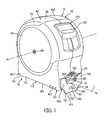
FIG. 1 shows a perspective view of a rule assembly in accordance with an embodiment of the present disclosure; -
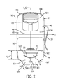
FIG. 2 shows a front of elevational view of the rule assembly in accordance with an embodiment of the present disclosure; -
FIG. 3 shows a side of elevational view of the rule assembly in accordance with an embodiment of the present disclosure; -
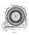
FIG. 4 shows a cross-sectional view of the tape rule assembly taken through the line 4-4 inFIG. 2 showing a blade thereof in a fully retracted configuration in accordance with an embodiment of the present disclosure; -
FIG. 5 is a view similar toFIG. 4 except showing the blade in a fully extended configuration in accordance with an embodiment of the present disclosure; -
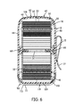
FIG. 6 is a cross-sectional view taken through the line 6-6 inFIG. 3 ; -
FIG. 7 is a detailed cross-sectional view of the opening, flexible cover, and end hook member of the rule assembly inFIG. 4 with the blade in a fully retracted configuration in accordance with an embodiment of the present disclosure; -
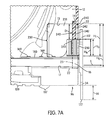
FIG. 7A is a detailed cross-sectional view of the rule assembly ofFIG. 7 in a first position with some parts removed to show further details of the opening, an upper portion of the opening, a mouth of the opening, the flexible cover and the end hook member in accordance with an embodiment of the present disclosure; -
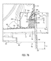
FIG. 7B is a detailed cross-sectional view of the rule assembly ofFIG. 7 in a second position with some parts removed to show further details of the opening, an upper portion of the opening, a mouth of the opening, the flexible cover and the end hook member in accordance with an embodiment of the present disclosure; -
FIG. 8 is a detailed front view of the opening and end hook member of the rule assembly in a first position in accordance with an embodiment of the present disclosure; -
FIGS. 9 and10 are detailed perspective and side views of the rule assembly as shown inFIG. 8 ; -
FIGS. 11 and12 are cross-sectional views of the tape rule assembly taken through the line 11-11 inFIG. 9 and line 12-12 inFIG. 10 , respectively, in accordance with an embodiment of the present disclosure; -
FIG. 13 is a detailed front view of the opening and end hook member of the rule assembly in a second position in accordance with an embodiment of the present disclosure; -
FIG. 13A is a detailed front view of the opening and end hook member of the rule assembly in a second position in accordance with another embodiment of the present disclosure; -
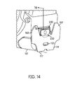
FIGS. 14 and15 are detailed perspective and side views of the rule assembly as shown inFIG. 13 ; -
FIGS. 16 and17 are cross-sectional views of the tape rule assembly taken through the line 16-16 inFIG. 14 and line 17-17 inFIG. 15 , respectively, in accordance with an embodiment of the present disclosure. -
FIG. 18 shows a cross-sectional view of the tape rule assembly showing a blade thereof in a fully retracted configuration in accordance with another embodiment of the present disclosure; -
FIG. 19 shows a cross-sectional view of the tape rule showing a blade thereof in a fully retracted configuration in accordance with yet another embodiment of the present disclosure; -
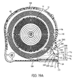
FIG. 19A shows a cross-sectional view of the tape rule showing a blade thereof in a fully retracted configuration in accordance with yet another embodiment of the present disclosure; -
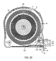
FIG. 20 shows a cross-sectional view of the tape rule assembly showing a blade thereof in a fully retracted configuration in accordance with still yet another embodiment of the present disclosure; -
FIGS. 21A and 21B each show examples of a side elevational view of a rule assembly when impacted by a force. - The disclosed assembly improves, among other things, the drop resistance of the hook as well as reduces the deformation of the hook during impact.
-
FIGS. 1-6 show arule assembly 10 in accordance with various embodiment of the present disclosure. The rule assembly shown inFIGS. 1-6 can, for example, be of the type illustrated and described inU.S. Patent No. 8,117,763, issued February 21, 2012 , entitled "Tape Rule and End Hook Therefore", incorporated herein by reference in its entirety. The rule assembly can be one of the type illustrated and described inU.S. Patent No. 6,282,808, issued on September 4, 2001 , which is hereby incorporated by reference in its entirety. The rule assembly can alternatively be one of the type illustrated and described inU.S. Patent No. 8,528,222, issued on September 10, 2013 , and/orU.S. Patent No. 8,375,595, issued on February 19, 2013 , both of which are incorporated herein by reference in their entirety. - It should be expressly recognized and appreciated, however, that the description and illustrations relating to
FIGS. 1-6 are examples only, and that the present disclosure applies much more broadly to elongated tape rule devices of many kinds and sizes, and having blades of different possible materials. - In general, the
rule assembly 10 includes ahousing 12, a reel 14 (as shown inFIGS. 4 and5 ) rotatably mounted in thehousing 12, and anelongated blade 16 having anend hook member 34 on afree end 20 thereof. Theelongated blade 16 is arranged to be wound on thereel 14 and has a free end configured to extend through anopening 22 andmouth 25 in thehousing 12. - The
reel 14 is mounted in thehousing 12 by areel spindle 15 that is secured within the housing 12 (FIGS. 4-6 ). An elongatedtape rule blade 16 is mounted on thereel 14. - The
blade 16 is formed of a ribbon of metal, e.g., steel, and the top concave surface of the blade is printed with measuring lines and digits (not shown) for measuring lengths and distances. Onelongitudinal end 18 of theblade 16 is connected to thereel 14 and a second longitudinalfree end 20 of the blade 16 (that is opposite to the connected end 18) that is arranged to be extendable generally outwardly of thehousing 12 through theopening 22. The "free end" 20 of theelongated blade 16 generally refers to an end region of theblade 16, such end region being configured for receipt of and/or connecting with anend hook member 34, one ormore rivets 169, and (optionally) one or more attachment assemblies (e.g., such asattachment assembly 250 to be described herein). Theblade 16 is constructed and arranged with respect to thehousing 12 to extend generally from a position tangential of thereel 14 outwardly through a spacedopening 22 provided in the housing 12 (as shown, for example, in a longitudinal direction L inFIG. 1 ). Theblade 16 can be extended from the housing by pulling on the free end of the elongated blade 16 (e.g., via grasping the end hook member 34). - The
blade 16 is generally movable between a fully retracted position outwardly of thehousing 12 to a fully extended position (moved or pulled in a longitudinal direction, L). The fully retracted position of theblade 16 is shown inFIG. 4 and the fully extended position of the blade is shown (in fragmentary view) inFIG. 5 . When theblade 16 is fully retracted into the housing 12 (e.g., such as shown inFIGS. 1 ,3 and4 ), theblade 16 may be extracted by pulling thehook member 34 from behind its lower edge (i.e., below the blade 16). In one embodiment, theend hook member 34 gives the user access to extract thehook member 34 from its side edges as well. It can be appreciated from a comparison ofFIG. 4 andFIG. 5 that as the blade is unwound from thereel 14, thecoil spring 32 is wound around the rigidly fixedspindle 15. This winding of the spring around the spindle stores energy in the spring to provide spring powered rewinding of theblade 16 around thereel 14 when the extended blade is released. - The details of the internal structure of the
housing 12 and theblade 16 mounted therein are shown inFIGS. 4-6 . In one embodiment, thehousing 12 and thereel 14 are constructed of a molded plastic. As best appreciated fromFIG. 6 , thehousing 12 includes a pair of cooperating moldedplastic housing members housing member end wall peripheral wall free edge housing members rule assembly 10 by a plurality of axially extendingbolts 58 extending through one of the housing members (e.g., member 42) and threadedly engaging the other housing member (e.g., member 40). Thehousing members bolts 68 with the fixedreel spindle 15. Theaxially extending spindle 15 is fixed at a central portion of thehousing assembly 12. Thetop portion 108 of thehousing 12 can be made to have a relatively arcuate profile (FIG. 2 , for example) that generally conforms to the profile of the reel, in accordance with embodiments. Ametal clip 77 is secured to one side of the housing assembly by one of thebolts 68. - In accordance with an embodiment, a peripheral portion of
housing 12 is provided with agrip cover 110 or coating thereon. Thegrip cover 110 or coating may be made of elastomeric material, e.g., rubber or a rubber-like polymeric material that is overmolded onto thehousing 12, and provided in any number of locations on the housing, such as around the gripped portion of thehousing 12 and near theopening 22 of thetape rule assembly 10. - The
housing 12 includes a bottom wall 109 (FIGS. 1 and4-5 ) having anexterior portion 107 at a forward end position (at a corner 96) adjacent (below) the housing opening 22 (andmouth 25 as illustrated inFIG. 7A ). Onecorner 96 is adjacent thehousing assembly opening 22 and theother corner portion 98 is at an opposite bottom end of thehousing assembly 12. Anexterior surface portion 111 extends from theforward end portion 107 atcorner 96 toward an opposite end 113 (at corner 98) of thebottom wall 109 to provide a finger grip enhancing configuration, generally designated 119 for a gripping hand of the user. That is, thebottom wall 109 has aforward end portion 107 adjacent thehousing opening 22 and arearward end portion 113 at the opposite end of thebottom wall 109. In an embodiment, thesurface portion 111 of thewall 109 therebetween may be generally recessed to provide the fingergrip enhancing configuration 119 for the gripping hand of the user. This recessed area or gripping area of the fingergrip enhancing configuration 119 on the bottom of thehousing 12 is, in one embodiment, completely covered with an overmolded rubber or rubber-like polymeric material (e.g., TPE, TPU) and may be formed with thegrip cover 110. - A holding assembly, generally designated to 124, is constructed and arranged to be manually actuated to hold the
blade 16, using a holdingmember 128 mounted on thehousing 12, in any position of extension outwardly of thehousing opening 22 and to release theblade 16 from any position in which it is held. The holdingmember 128 has an exteriorthumb engaging portion 132 configured to be moved digitally to selectively move an interior holding structure 130 (FIG. 5 ) of the holdingmember 128 between its normally inoperative position and its holding position, as shown inFIGS. 4 and5 , respectively. The exteriorthumb engaging portion 132 is best seen inFIGS. 1-2 . Such features are not described in great detail herein as one of ordinary skill in the art understands how the holdingassembly 124 is used and moved between its positions to release and hold theblade 16. It should be appreciated that other holding assemblies, such as those that automatically hold theblade 16 in a position of extension, and are manually actuated to release the blade can also be used. In yet another embodiment, no holding assembly need be provided. - As shown in
FIGS. 1-4 , anend hook member 34 is attached to thefree end 20 of theelongated blade 16. Theend hook member 34 includes a mountingportion 150 connected to thefree end 20 of the elongated blade 16 (in overlying relation thereto) and ahook portion 152 extending generally perpendicularly from the mountingportion 150 at thefree end 20 of theelongated blade 16. Thehook portion 152 can be bent at a generally right angle from an end of the mountingportion 150. In one embodiment, the connection between theblade 16 and the mountingportion 150 may permit limited sliding movement therebetween. Thehook portion 152 may include anopening 151 or hole therein to help temporarily secure an end of thehook portion 152 to an object (e.g., via insertion of a pin or nail through the opening 151). - In one embodiment, the
hook portion 152 ofend hook member 34 is constructed and arranged to extend downwardly below abottom wall 109 or surface of thehousing 12 when at the opening 22 (or mouth) in thehousing 12, when theelongated blade 16 in a fully retracted position. As shown inFIG. 7 , a portion of thehook portion 152 that extends downwardly below thebottom surface 109 or wall of thehousing 12 has a height dimension of H (height H is defined as the distance between thebottom surface 109 or wall of thehousing 12 and thebottom edge 177 of the hook portion 152). - In one embodiment, the
end hook member 34 is formed of, for example, a sheet metal material (such as steel), of a predetermined thickness, that is stamped or otherwise formed into a desired shape. - In one embodiment, the mounting
portion 150 has a generally concavo-convex configuration (e.g., to match the concavo-convex curvature of the blade 16). In another embodiment, the mountingportion 150 has a generally flat configuration. - The mounting
portion 150 is provided withholes 167 that may be substantially aligned with openings in theelongated blade 16. A plurality ofrivets 169 extend through theholes 167 and openings in theblade 16 to slidably mount theend hook member 34 to theblade 16 for limited longitudinal relative movement between theend hook member 34 and the blade 16 (i.e., the diameter of eachhole 167 is greater than the diameter of the associatedrivet 169 by an amount approximately equal to the desired amount of hook movement). The limited sliding engagement allows theblade 16 to be measured externally from anexternal surface 161 of thehook portion 152 or internally from aninternal surface 163 of thehook portion 152. In other words, the sliding movement of theend hook member 34 allows an accurate measurement to be taken with eithersurface end hook member 34 may slide longitudinally with respect to the blade 16 a distance approximately equal to the thickness of the hook portion 152 (where the thickness is measured fromsurface 161 to surface 163) so that a measurement taken with eithersurface - The dimensions and features of the tape measure mechanism, housing, blade and/or hook member should not be limiting. For example, in some embodiments, the
end hook member 34 may be designed with top catching capability, which generally refers to the ability of a portion of theend hook member 34 to hookingly engage with a work-piece to facilitate extension of theblade 16 and to temporarily secure the blade to the work-piece while a measurement is being taken. In such an embodiment, the portion of theend hook member 34 may be a) located above theblade 16 and/or b) located above and to the side of theblade 16. In one embodiment, thehook portion 152 is substantially U-shaped. In another embodiment, thehook portion 152 of thehook member 34 provides an under-catch structure and/or a side catch structure that can hookingly engage a work-piece to facilitate extension of theblade 16 and to temporarily secure the blade to the work-piece while a measurement is being taken. In yet another embodiment, thehook portion 152 may comprise burred portions (e.g., to provide a gripping attribute to edges of the hook member 34). Also, the spacing and depiction of therivets 169 should not be limited to the illustrated embodiments. For example, the two or more rivets may be positioned such that they are equidistant. - In one embodiment, the
U-shaped hook portion 152 includes abight section 160 and spacedleg sections 162 extending upwardly from thebight section 160. In one embodiment, thebight section 160 of theU-shaped hook portion 152 is configured to extend downwardly, below a convex side of thefree end 20 of theblade 16. Thebight section 160 of thehook portion 152 of thehook member 34 provides an under-catch structure that can hookingly engage a work-piece to facilitate extension of theblade 16 and to temporarily secure the blade to the work-piece while a measurement is being taken. - In one embodiment, the
leg sections 162 extend laterally outwardly beyond the longitudinally extending edges of theblade 16 to provide a side catch surface on each side of theblade 16 that can be used to hook theblade 16 to an object or work-piece. The side catch structure provided by thelegs 162 can function to secure thefree end 20 of theblade 16 during a measurement. The side catch structure provided by theleg sections 162 also allow theblade 16 to be easily and steadily held in a tilted position relative to a surface of the work-piece, thereby allowing a longitudinally extending edge of theblade 16 to be held against the work-piece. - In one embodiment, the
leg sections 162 extend laterally beyond transversely spacedcorners 171 of thefree end 20 of theblade 16. In one embodiment, thecorners 171 at the front edge of the blade are chamfered or angled. - In one embodiment, the upper portions of the
leg sections 162 extend generally upwardly and outwardly above the concave side of theblade 16 to provide structure above the concave surface of theblade 16 to hookingly engage the work-piece to facilitate extension of theblade 16 and to hold thefree end 20 of theblade 16 while a measurement is being read. For example, theblade 16 can be placed against a work-piece such that the concave side of theblade 16 is facing the work-piece and such that the opposite longitudinal edges of theblade 16 abut a surface on the work-piece at a point where they measurement is to be read. When theblade 16 is in this position, the upwardly extending portions of thelegs 162 on thehook member 34 can be used to hold thefree end 20 of theblade 16 against the work-piece. - In one embodiment, the
leg sections 162 extend upwardly above both the mountingportion 150 and the spacedcorners 171 of thefree end 20 of theblade 16. - Further details of the construction of the
housing opening 22 and interior of thehousing 12 adjacent to theopening 22 can be appreciated fromFIGS. 2 ,4 and7 . Thehousing opening 22 has a height dimension Ho, as seen inFIG. 2 andFIG. 4 , for example. As shown inFIG. 7A , the height Ho of theopening 22 extends betweensurfaces housing 12 through which theelongated blade 16 andend hook member 34 extend, allowing theblade 16 to be moved between fully retracted and extended positions. More specifically, thetop surface 13 of theopening 22 is defined in one embodiment as the part where the structural rigid portion of thehousing 12 ends and a flexible portion, e.g., flexible cover 240 (as further described below), begins. Thebottom surface 17 of theopening 22 is defined in one embodiment as the surface in which theblade 16 is adjacent to and/or rests on when theblade 16 is in the fully retracted position. In one embodiment, thesurfaces mouth region 25 discussed later. In one embodiment, arigid portion 19 of thehousing 12, also discussed later, is the top surface of theopening 22. - The
opening 22 of thehousing 12 has anupper portion 230, as shown inFIG. 7A , so as to be disposed above theelongated blade 16 and the mountingportion 150 when theblade 16 is fully retracted. More specifically, theupper portion 230 of theopening 22 includes the space between the upper surface of theblade 16 and atop surface 13 of the relatively structural rigid portion of thehousing 12 that defines a top of theopening 22 in thehousing 12. Theupper portion 230 has a height dimension HT, as seen inFIG. 7 andFIG. 7A , for example. Additional features relating to theopening 22 andupper portion 230 of the opening are noted later. - The housing also has a
flexible cover 240 or flange. Theflexible cover 240 is disposed above a free end of theelongated blade 16, and above or adjacent a top concave surface or side of theblade 16. In an embodiment, theflexible cover 240 overhangs at least a part of, if not the entirety of, theupper portion 230 of theopening 22 or mouth. Theflexible cover 240 inhibits and/or substantially prevents penetration of debris or dirt into the housing through theupper portion 230 of theopening 22. Theflexible cover 240 is positioned to be flexed or compressed by the end hook member 34 (directly or indirectly) upon impact by force thereon (e.g., from impact, e.g., when dropped to the floor or ground) and permits movement theend hook member 34 into at least theupper portion 230 of theopening 22. In accordance with an embodiment, as described below, theflexible cover 240 may also or alternatively be flexed or compressed by anattachment assembly 250 mounted above the mountingportion 150 of thehook member 34, as will be described. - In an embodiment, the
flexible cover 240 extends downwardly from arigid portion 19 of thehousing 12 towards the end hook member 34 (e.g., seeFIG. 7A ).Rigid portion 19 may represent a part of the outer wall of thehousing 12. Therigid portion 19 may be provided in addition to, or alternative to, thetop surface 13 of the opening. In one embodiment, therigid portion 19 itself comprises thetop surface 13 of the opening. That is, a separatetop surface 13 as shown inFIG. 7A , that extends further into the housing need not be provided. The depiction ofFIG. 7A is exaggerated, with some parts removed, to show further details of theopening 22, anupper portion 230 of the opening, amouth 25 of the opening, theflexible cover 240 and theend hook member 34 in a first position. Theflexible cover 240 may be considered part of the housing, or a separate component or set of components attached to the housing. Thecover 240 extends a length or distance D downwardly from a top of theupper portion 230 of theopening 22 towards theend hook member 34, as shown inFIG. 7 , for example. In an embodiment, thecover 240 covers approximately ½ of the upper portion 230 (e.g., the top half). In another embodiment, theflexible cover 240 extends over (covers) less than ½ of theupper portion 230. In another embodiment, theflexible cover 240 extends over a majority (more than ½) of the height of theupper portion 230 of theopening 22. That is, in one embodiment, the length or distance D of theflexible cover 240 that covers theopening 22 is greater than half the height HT of the upper portion 230 (D > ½ HT). In an embodiment, theflexible cover 240 extends over the entireupper portion 230. That is, the length or distance D of the flexible cover is about the same as or equal to the height HT of the upper portion 230 (D = HT). - The upper portion of the "opening" into the housing (e.g., upper portion 230) as referred to herein includes the volume of space occupied by the
flexible cover 240 itself, and (at least in some embodiments) will also include a volume of space behind the flexible cover 240 - or "cover receiving void" 231 - into which theflexible cover 240 may be flexed or displaced. In an embodiment, thecover receiving void 231 is also configured to receive at least a part of an attachment assembly 250 (if provided) upon its displacement (e.g., via force onend hook member 34 itself or theattachment assembly 250 itself). Theupper portion 230 has a height dimension HT, as seen inFIG. 7 andFIG. 7A , for example. Thecover receiving void 231 has a height dimension that is equal to the length of the flexible cover (e.g., length D, extending fromtop surface 13 of amouth 25 of thehousing 12 to abottom surface 243 of the flexible cover 240). A depth of the cover receiving void 231 (into the housing 12) is defined by the position in which adistal bottom surface 243 of the flexible cover 240 (the end opposite the end extending downwardly from theopening 22 and/or from therigid portion 19 of the housing) is flexed or compressed into at least theupper portion 230 of theopening 22 when impacted by force (e.g., see flexed position inFIG. 7B ). In accordance with an embodiment, the depth of theupper portion 230 of the opening 22 (and thus, the depth of the cover receiving void 231) is greater than the position in which thebottom surface 243 of theflexible cover 240 is flexed or compressed. - The "mouth" 25 of the
opening 22 refers to the portion of the opening that is at the immediate entranceway into thehousing 12, and can optionally also be considered to include the volume of space occupied by the flexible cover, as depicted inFIG. 7A . The "mouth" 25 of the opening does not include portions of the opening that are behind the flexible cover and behind the immediate initial rigid surface (e.g., surface 19) (if such surface is present) definingopening 22 when the cover is unflexed (or in a first or neutral position). - Further, as shown in
FIGS. 7A and7B , theflexible cover 240 has a front surface that appears to include a recess. For example, as seen inFIG. 9 , theflexible cover 240 may, in one embodiment, be slightly recessed into thehousing 12 and/or relative to the exterior wall (e.g,. recessed relative to a grip portion 110). However, it should be noted that theflexible cover 240 need not include any recess therein. Instead, as represented inFIG. 1 , for example, theflexible cover 240 may extend straight down relative to thehousing 12 and/or be incorporated into the tape assembly 10 (e.g., into thegrip portion 110 or housing 12). Further, theflexible cover 240 need not be aligned on or secured to therigid portion 19 of thehousing 12. - In an embodiment, the hook portion 152 (e.g., via its spaced leg sections 162) is configured to always engage or contact the
flexible cover 240 when theblade 16 is in the fully retracted position. In another embodiment, thehook portion 152 does not contact theflexible cover 240 when theblade 16 is in the fully retracted position. - A gap may be provided between the top surface of the
elongated blade 16 and theflexible cover 240. As shown inFIG. 7 , the gap has a height HG. - In an embodiment, the height H of the
hook portion 152 extending below thebottom surface 109 of thehousing 12 is less than the height HT of the upper portion 230 (H < HT). In an embodiment, the height H of thehook portion 152 extending below thebottom surface 109 of thehousing 12 is substantially equal to or equal to the height HG of the gap (H = HG). In an embodiment, the height H of thehook portion 152 extending below thebottom surface 109 of thehousing 12 is greater than the height HG of the gap (H > HG). In an embodiment, the height H of thehook portion 152 extending below thebottom surface 109 is less than the height HG of the gap (H < HG). - The
flexible cover 240 may includeridges 242 or ribs therein to facilitate, aid, and/or enable the flexion of the body of theflexible cover 240 in at least substantially vertical direction when force is applied thereto. Theseridges 242 or ribs may be molded, machined, or added, for example, in or to theflexible cover 240. - In an embodiment, the
flexible cover 240 is configured to compress, bend, fold, and/or collapse when impacted. Theflexible cover 240 may include a compressible material. Theflexible cover 240 may also and/or alternatively be shaped or formed in a manner and/or include a geometry and/or material (e.g., foam, rubber, elastomer) that is compressible such that it is configured to compress upon application of a force F and/or F2. - In an embodiment, the
flexible cover 240 is formed from a resilient material. Theflexible cover 240 may also and/or alternatively be shaped or formed in a manner and/or include a geometry that is resilient, such that it is configured to return to its original shape after flexion and/or application of a force F and/or F2. Theridges 242 or ribs may assist in the resiliency of the flexible cover in that it may add rigidity to the flexible cover to assist in the cover's return to its original position and shape, and/or to ensure that an impact does not cause permanent deformation or damage to theflexible cover 240. - In one embodiment, the
cover 240 may be formed from an elastic material or elastomeric material. In an embodiment, thecover 240 is made from a rubber or a rubber-like polymeric material. In an embodiment, thecover 240 is made from TPU or TPE (Thermoplastic Elastomer). In an embodiment, the cover 24 is formed of a material that is relatively softer and/or relatively more compliant and flexible than the material used to form the main structural component of theouter housing 12. In one embodiment, thecover 240 is integrally formed as part of thegrip cover 110 or coating (e.g., made of elastomeric material) on thehousing 12 and acts as a hinge for flexion of the flexible cover. Just one example of such an embodiment is described later with respect toFIG. 18 . - Under normal operation, the
cover 240 hides at least theupper portion 230 of theopening 22. For example,FIG. 8 shows theend hook member 34 in a first position, or an un-flexed or uncompressed position, wherein therule assembly 10 is configured for normal operation, with theblade 16 fully retracted, and theflexible cover 240 is fully extended at its distance D. As shown in detail inFIGS. 9-12 , when theelongated blade 16 is in a fully retracted position, the mountingportion 150 of theend hook member 34 is received in theopening 22, thehook portion 152 extends downwardly below abottom surface 109 orexterior portion 107 of thehousing 12, and theflexible cover 240 at least overhangs or covers at least a portion of theupper portion 230 of theopening 22 to hide at least theupper portion 230 and inhibit entry of debris into theopening 22. - The
flexible cover 240 is positioned to absorb force from upward impact onto the hook and permit movement of portions of the end hook member 34 (e.g., mounting portion 150) into the upper portion 230 (and, in some instances, movement of anattachment assembly 250 into the upper portion 230 (and/or void 231)). For example, as noted inFIGS. 8 and10 , when an impact force - e.g., such as a substantially upward force as noted by arrow F or an angular force as noted by arrow F2 - is applied to abottom edge 177 of theend hook member 34, theend hook member 34 is moved substantially upwardly relative to theopening 22 of thehousing 12, e.g., substantially in a direction as indicated by arrow U or angular direction relative to the housing (not shown). During impact, then, as theend hook member 34 is moved, it in turn impacts or moves theflexible cover 240. Thecover 240 is flexed in a direction C (e.g., flexed, collapsed, moved, pivoted, displaced, and/or compressed substantially vertically, or substantially laterally, or substantially angularly, relative to the longitudinal direction L for pulling theblade 16 from the housing 12). Movement of theend hook member 34 into theupper portion 230 aids in reducing or preventing deformation of theend hook member 34. - It can be appreciated from
FIG. 7 that in an exemplary embodiment of thetape assembly 10, theupper portion 230 of theopening 22 is disposed generally above the mountingportion 150 of thehook member 34 when thehook member 34 is at theopening 22. Theupper portion 230 and cover 240 are provided in and on thehousing 12, respectively, so that if theend hook member 34 is caused to move substantially upwardly in theopening 22 and into theupper portion 230 because of an impact (e.g., by application of a force F or force F2, in a substantially upward direction U or angular direction relative to thehousing 12, respectively, onto abottom edge 177 of theend hook member 34, such as when dropped on a floor or ground G as shown inFIGS. 21A and 21B ), thehook member 34 is free to move to a second position (where theblade 16 is flexed), as shown inFIG. 13 orFIG. 13A , towards and/or into cover receiving void (seeFIG. 7A ) and not stopped in themouth 25 of theopening 22. Thebottom edge 177 can move substantially upwardly to a position substantially in line with (or flush with) the bottom end surface orportion 107 of thehousing 12. In an embodiment theflexible cover 240 is compressed by theend hook member 34, as shown inFIGS. 15 and17 . Thecover 240 may be flexed or compressed to a length or distance D2 from a top of theupper portion 230 of theopening 22 towards theend hook member 34, as shown inFIG. 7B orFIG. 17 , for example. The flexion and/or compression of theflexible cover 240 reduces the force that is applied to theend hook member 34 and allows it to recess into theupper portion 230. - In an embodiment, the elongated blade and end hook member are at least partially in the
upper portion 230 in the second position upon or after substantially upward impact by force on abottom edge 177 of thehook portion 152. In an embodiment, thehook portion 152 is at least partially in theupper portion 230 in the second position. In an embodiment, thecover 240 is flexed or moved at least partially into theupper portion 230 in the second position upon or after impact by force, such that the hook may enter theupper portion 230. - As shown in
FIG. 4 andFIG. 7 , the height dimension Ho of theopening 22 may be measured from thetop surface 13 of the structural rigid portion of the housing 12 (at the opening 22) to the bottom surface 17 (at the opening 22) of the structural rigid portion of thehousing 12. In one embodiment, to accommodate movement of theend hook member 34 into theupper portion 230, the height HT of theupper portion 230 extending above the hook portion between the structural rigid portion of thehousing 12 and the top of theelongated blade 16 exceeds a height dimension H of a portion of thehook portion 152 that extends downwardly below thebottom surface 109 orportion 107 of thehousing 12. Theupper portion 230 is of a height HT to operatively accommodate the movement of the at least a portion of theend hook member 34 therein. For example, theupper portion 230 may be sized to accommodate movement of at least the mountingportion 150 therein. The height HT of theupper portion 230 is provided to substantially prevent possible damage to theend hook member 34 when theblade 16 is fully retracted and theend hook member 34 is impacted (by dropping or the like) in a direction (arrow U) that tends to move theend hook member 34 substantially upwardly with respect to theopening 22. - In one embodiment, the
end hook member 34 initially contacts theflexible cover 240 prior to thebottom 177 of thehook portion 34 being at the height of thebottom surface 109 of thehousing 12. Theflexible cover 240 flexes sufficiently to enable thebottom 177 of theend hook member 34 to reach the height of thebottom surface 109 of thehousing 12. In one embodiment, theflexible cover 240 flexes, collapses, moves, compresses, pivots, and/or displaces upwardly by at least 1/8" to accommodate the upward blade and/or hook movement. In another embodiment, thecover 240 has sufficient compressibility and/or flexibility to be moved or displaced between 1 /8" and ½". In another embodiment, such movement or displacement is at least ¼". As noted later, the displacement of theflexible cover 240 by at least 1/8" refers to a height difference between abottom surface 243 of theflexible cover 240 in a first position and thebottom surface 243 of theflexible cover 240 when in the second position upon impact by force. -
FIG. 18 shows a cross-sectional view of the tape rule assembly showing a blade thereof in a fully retracted configuration in accordance with another embodiment of the present disclosure. Thehousing 12 has aflexible cover portion 265 that is received and disposed in theupper portion 230 of opening 22, belowtop surface 13 ofhousing 12 and above theelongated blade 16 and the mountingportion 150 when theelongated blade 16 is in the fully retracted position. Theflexible cover portion 265 includes aresilient hinge 260 and arigid structure 270. Theresilient hinge 260 acts as a hinge or flexible member that allows movement of therigid structure 270 of thecover portion 265 relative to theopening 22 andhousing 12. That is, theresilient hinge 260 flexes, collapses, moves, compresses, pivots, and/or displaces such that therigid structure 270 is moved or displaced. Accordingly, should theend hook member 34 be impacted by force, and thus moved into contact with therigid structure 270, therigid structure 270 may be moved relative to the housing 12 (e.g., in a substantially upward and/or rearward direction (into the housing 12), such as previously described with reference to arrow U and the Figures above) by transfer of force through therigid structure 270 to flex theresilient hinge 260, which absorbs the applied force from the impact. In an embodiment, therigid structure 270 is moved or displaced further into, or rearwardly within, theupper portion 230 of theopening 22, and, more specifically, into thecover receiving void 231 in the housing 12 (as shown inFIG. 7A , for example). - In one embodiment, the
resilient hinge 260 is part of thegrip cover 110, as shown inFIG. 18 . Theresilient hinge 260 may be integrally formed as part of thegrip cover 110 or coating (e.g., made of elastomeric material) on thehousing 12, or attached thereto. For example, a peripheral portion ofhousing 12 may be provided with agrip cover 110 or coating thereon (e.g., such as previously described above). Thegrip cover 110 or coating may be made of elastomeric material, e.g., rubber or a rubber-like polymeric material or TPU (Thermoplastic polyurethane) or TPE (Thermoplastic elastomer), that is overmolded onto thehousing 12, and provided in any number of locations on the housing, such as around the portion of thehousing 12 to be gripped during use and/or near theopening 22 of thetape rule assembly 10. Theresilient hinge 260 may be made of similar or the same elastomeric material, e.g., rubber or a rubber-like polymeric material or TPU (Thermoplastic Polyurethane) or TPE (Thermoplastic Elastomer). Theresilient hinge 260 may be formed integrally with thegrip cover 110 or formed separately. - In one embodiment, the
resilient hinge 260 has a length or thickness S, as shown inFIG. 18 , in the vertical direction. Therigid structure 270 can be sized to have a width or thickness T, as shown inFIG. 18 , in the horizontal direction. In one embodiment, thehousing 12 includes an opening or area (e.g., hole) for receipt of theresilient hinge 260 therein. In one embodiment, the opening or area on thehousing 12 is dimensioned to be similar or substantially equal to theresilient hinge 260. For example, the length or thickness of the opening or area in a vertical direction may be substantially equal to length S of theresilient hinge 260, such that theresilient hinge 260 can be press fit therein. Theresilient hinge 260 is configured to flex, collapse, move, pivot, displace, and/or compress when therigid structure 270 is moved or displaced (by force) by the end hook member 34 (with or without attachment assembly 250) and/or adjacent portions of theblade 16. The width or thickness T of therigid structure 270 may be based on a length that theresilient hinge 260 extends (in a horizontal direction) into thehousing 12, or vice versa (i.e., the length of theresilient hinge 260 in the horizontal direction into the housing is based on the thickness T of the rigid structure 270). - In an embodiment, the
housing 12 and therigid structure 270 are formed of similar or the same materials. In one embodiment, thehousing 12 and therigid structure 270 are formed from an Acrylonitrile Butadiene Styrene (ABS) plastic. In an embodiment, theresilient hinge 260 is formed from TPE (thermoplastic elastomer) or TPU (thermoplastic polyurethane) or a resilient material. Of course, other materials, such as polycarbonates and/or combinations of materials, may also be used to form thehousing 12 andrigid structure 270 of theflexible cover portion 265. - In one embodiment, the
grip cover 110 and theresilient hinge 260 are formed from TPE or TPU or a resilient material. - In an alternate embodiment, the
resilient hinge 260 provided between thehousing 12 and therigid structure 270 may take the form of a metal spring. - Of course it should be noted that the
resilient hinge 260 andrigid structure 270 of theflexible cover portion 265 are not intended to be limited to the shape, configuration, dimensions, and/or materials shown in the Figure and noted above. -
FIG. 19 illustrates yet another embodiment of thetape rule assembly 10 having aflexible cover 280. As shown, theflexible cover 280 is formed as part of aperipheral wall 50 of thehousing 12. In an embodiment, thebody 282 of theflexible cover 280 is formed of similar or the same material as thehousing 12. Theflexible cover 280 includes abody 282 that extends into anupper portion 230 of theopening 22 and rearwardly within thehousing 12. Theflexible cover 280 may also include acontact portion 284 for contact or impact by theend hook member 34 or an attachment assembly 250 (if included thereon) when theend hook member 34 /attachment assembly 250 is moved or forced into contact with theflexible cover 280. Thecontact portion 284 may be a part of thebody 282, e.g., integrally formed therewith, or attached to thebody 282. In an embodiment, as shown inFIG. 19 , thecontact portion 284 may extend in a substantially horizontal direction relative to theblade 16 and/or the mountingportion 150 of theend hook member 34. Thecontact portion 284 is provided within theopening 22 of thehousing 12. In an embodiment, thebody 282 offlexible cover 280 covers a majority (more than ½) of the height of theupper portion 230 of theopening 22. - In an embodiment, the
body 282 of the flexible cover has a geometry such that it can move or bend upon impact (e.g., via contact withend hook member 34 or blade 16). In an embodiment, at least thebody 282 of theflexible cover 280 is resilient and configured to return to its original shape. For example, at least thebody 282 may be formed from a resilient material. Thebody 282 may be formed or shaped into a resilient structure and/or include a geometry that is resilient, such that it is configured to return to its original shape after flexion and/or application of a force F and/or F2. For example, thebody 282 may be formed into a resilient U-shape, V-shape, W-shape, S-shape, or other shape that facilitates flexion. Thebody 282 of theflexible cover 280 extends from and/or is connected to thehousing 12 near or at thetop surface 13 via aliving hinge 281, in accordance with one embodiment. The livinghinge 281 allows for flexing of thebody 282 relative to thetop surface 13 of thehousing 12 when force is applied to theflexible cover 280. In an embodiment, as shown inFIG. 19 , thebody 282 is "V"-shaped and allows for flexing or movement when force applied to thecontact portion 284 of theflexible cover 280. Accordingly, the V-shape of thebody 282 can flex when force is applied to theflexible cover 280 and absorb or dampen the impact. - In an embodiment, the
body 282 of theflexible cover 280 may be formed of similar or the same material as thegrip cover 110, for example, as shown inFIG. 19A . Similar reference numbers are used inFIG. 19A as inFIG. 19 to reference similar parts. Theflexible cover 280 includes abody 282 that extends into anupper portion 230 of theopening 22 and rearwardly within thehousing 12. Theflexible cover 280 may also include acontact portion 284 for contact or impact by theend hook member 34 or an attachment assembly 250 (if included thereon) when theend hook member 34 /attachment assembly 250 is moved or forced into contact with theflexible cover 280. Thecontact portion 284 may be a part of thebody 282, e.g., integrally formed therewith, or attached to thebody 282. In an embodiment, as shown inFIG. 19A , thecontact portion 284 may extend in a substantially horizontal direction relative to theblade 16 and/or the mountingportion 150 of theend hook member 34. Thecontact portion 284 is provided within theopening 22 of thehousing 12. In an embodiment, thebody 282 offlexible cover 280 covers a majority (more than ½) of the height of theupper portion 230 of theopening 22. - In an embodiment, the
body 282 of the flexible cover inFIG. 19A has a geometry such that it can move or bend upon impact (e.g., via contact withend hook member 34 or blade 16). In an embodiment, at least thebody 282 of theflexible cover 280 is resilient and configured to return to its original shape. For example, at least thebody 282 may be formed from a resilient material. Thebody 282 may be formed or shaped into a resilient structure and/or include a geometry that is resilient, such that it is configured to return to its original shape after flexion and/or application of a force F and/or F2. For example, thebody 282 may be formed into a resilient U-shape, V-shape, W-shape, S-shape, or other shape that facilitates flexion. Thebody 282 of theflexible cover 280 is connected to thehousing 12 near or at thetop surface 13 via aliving hinge 281, in accordance with one embodiment. The livinghinge 281 allows for flexing of thebody 282 relative to thetop surface 13 of thehousing 12 when force is applied to theflexible cover 280. In an embodiment, as shown inFIG. 19A , thebody 282 is "V"-shaped and includes afirst portion 283 and asecond portion 285. In on embodiment, the first andsecond portions second portion 285 relative to thefirst portion 283 when force applied to theflexible cover 280. In an embodiment, thesecond portion 285 is configured to move thefirst portion 283. For example, thesecond portion 285 may bend or move upwardly relative to the first portion 283 (and housing 12) via the living hinge 287 as well as force or move thefirst portion 283 of thebody 282 relative to thehousing 12 via livinghinge 281 when force is applied to theflexible cover 280. Accordingly, the V-shape ofportions body 282 can flex when force is applied to theflexible cover 280 and absorb or dampen the impact. In one embodiment, thecontact portion 284 is connected to thesecond portion 285 of the body via aliving hinge 289. The livinghinge 289 allows for flexing of thecontact portion 284 when force is applied to theflexible cover 280. - In an embodiment, the
contact portion 284 may be formed of similar or the same material(s) as thegrip cover 110 orhousing 12. In one embodiment, thecontact portion 284 is formed from a different material than thebody 282 of theflexible cover 280. In an embodiment, at least thecontact portion 284 of theflexible cover 280 is formed of a resilient material. -
FIG. 20 illustrates still yet another embodiment of thetape rule assembly 10 having aflexible cover 252. Thehousing 12 has aflexible cover portion 252 that is received and disposed in theupper portion 230 of theopening 22, belowtop surface 13 ofhousing 12 and above theelongated blade 16 and the mountingportion 150 when theelongated blade 16 is in the fully retracted position. As shown,flexible cover 252 includes abody 254 that extends into anupper portion 230 of theopening 22 within thehousing 12. In an embodiment, thebody 254 offlexible cover 252 may extend into a majority of (more than ½) of the height of theupper portion 230 of theopening 22. Thebody 254 acts as a hinge or flexible member that moves relative to theopening 22 andhousing 12. That is, thebody 254 flexes, collapses, moves, compresses, pivots, and/or displaces when force is applied to theflexible cover 252. Accordingly, should theend hook member 34 be impacted by force, and thus moved into contact with thebody 254,body 254 may be moved relative to the housing 12 (e.g., in a substantially upward and/or rearward direction (into the housing 12), such as previously described with reference to arrow U and the - Figures above). Further, one or more parts of the
body 254 may flex relative to thehousing 12. For example, the body 253 may flex relative to atop surface 13 in thehousing 12. In an embodiment, thebody 254 is sized to contain the volume of thecover receiving void 231 of theupper portion 230 of theopening 22. - In an embodiment, the
outer body 254 of theflexible cover 252 further comprises acavity 256 therein. Thecavity 256 may be a hole surrounded or encompassed on all sides by walls of theouter body 254. - In one embodiment, the
cavity 256 is filled with amaterial 258. The material can be a gas, a gel, a liquid, or a combination thereof, for example. Theouter body structure 254 of theflexible cover 252, in one embodiment, is formed by a resilient material, such as an elastomer rubber material. Theflexible cover 252 may also and/or alternatively be shaped or formed in a manner and/or include a geometry that enhances its resilience, such that it is configured to return to its original shape after flexion and/or application of a force F and/or F2. The body 254 [and anymaterial 258 within the cavity 256] may be flexed upon application of force from theend hook member 34 when theend hook member 34 is impacted by force (e.g., impacted by force F and/or F2) to absorb such force. In accordance with an embodiment, thebody 254 of theflexible cover 252 may be then configured to return to its original shape after the end hook member 34 (orattachment assembly 250, or the device applying the impact) is moved out of contact with theflexible cover 252. - It should be understood that any of the dimensions previously disclosed with reference to
FIGS. 7-17 may, in some embodiments, also apply to the illustrative embodiments ofFIGS. 18-20 . For example, in one embodiment, thehousing opening 22 has a height dimension Ho, as defined above with reference toFIG. 4 , for example. Theupper portion 230 of theopening 22 in any ofFIGS. 18-20 has a height dimension HT, for example, that extends and is measured from thetop surface 13 of the structural rigid portion of thehousing 12 at theopening 22 to thebottom surface 17 of the structural rigid portion of thehousing 12 at theopening 22. Any of theflexible covers top surface 13 of the housing 12) towards theend hook member 34. In an embodiment, the length or distance D of the flexible cover is less than the height HT of the upper portion 230 (D < HT) for any ofFIGS. 18-20 . In an embodiment, theflexible cover upper portion 230 of theopening 22. In another embodiment, the length or distance D of theflexible cover flexible cover upper portion 230. To accommodate movement of theend hook member 34 into theupper portion 230 of theopening 22 in any ofFIGS. 18-20 , the height HT of theupper portion 230 extending above thehook portion 152, in one embodiment, exceeds a height dimension H of a portion of thehook portion 152 that extends downwardly below thebottom surface 109 orportion 107 of thehousing 12, as previously described. In one embodiment, theend hook member 34 initially contacts theflexible cover bottom 177 of thehook portion 34 being at the height of thebottom surface 109 of thehousing 12. In one embodiment, theflexible cover bottom 177 of theend hook member 34 to reach the height of thebottom surface 109 of thehousing 12. However, in other embodiments, thebottom 177 of thehook portion 34 stops just short of the height of thebottom surface 109 of the housing, so that it projects only slightly below the housing upon impact. - In accordance with various embodiments, including any of the embodiments shown and described herein, the
tape rule assembly 10 may accommodate anattachment assembly 250 removably attachable (directly or indirectly) onto the free end of theelongated blade 16, as shown inFIGS. 7-17 , for example. Specifically,FIGS. 7-17 illustrate an exemplary embodiment having anattachment assembly 250 comprising a magnet that is removably attachable to theelongated blade 16 viarivets 169. Theattachment assembly 250 may at least partially extend into (and may optionally be fully contained within) the upper portion of theopening 22 when the elongated blade assembly is in the fully retracted position. Also, in an embodiment, any force that is received by theend hook member 34 upon impact may be translated from theend hook member 34 to theattachment assembly 250, which in turn contacts the flexible cover to flex the flexible cover (e.g., cover 240), which flexible cover absorbs (or softens) the effect of the impact on the end hook member 34 (as well as softening the translated impact upon the housing 12). However, such embodiments are not intended to be limiting. For example, theattachment assembly 250 may be attached to theend hook member 34, in addition to, or instead of, therivets 169, or theblade 16. Theattachment assembly 250 may be applied to any of the embodiments disclosed with reference toFIGS. 18-20 , for example. For illustrative and explanatory purposes only, theattachment assembly 250 and its use with atape measure 10 is described with reference toFIGS. 7-17 . Further, instead of a magnet, anattachment assembly 250 may alternately be another utility device, instrument, or tool, and thus the type of attachment is not intended to be limited to that as illustrated in the Figures. For example, the attachment orattachment assembly 250 may comprise another hook, a light, a writing instrument, and/or a device for holding a writing instrument. - In some embodiments, the utility device, instrument or tool can be in addition to the
attachment assembly 250. Specifically, while theattachment assembly 250 in one embodiment is attached at the free end of the blade so as to be above the end hook mounting portion, an additional utility device, instrument or tool (such as an extended hook portion) can additionally be attached to the end portion, such as attached to the hook portion of theend hook member 34. In such embodiment, for example in addition toattachment assembly 250, a hook attachment is attached directly to the hook. In such embodiment, the impact may be translated to theend hook member 34 through the hook attachment (e.g., a magnet, pencil or additional hook extension attached to the downwardly depending portion (hook portion) of the end hook member. Further, the attachment assembly need not be configured such that it only extends above or on top of theend hook member 34 orblade 16. That is, the attachment may extend upwardly and/or downwardly relative to the free end of the blade, for example forwardly of or alongside the hook portion of theend hook member 34. - In one embodiment, the contact or impact with the ground that moves the free end of the
blade 16 upwardly is indirectly translated to the blade andend hook 34 through one of the utility device(s) that can be attached to theend hook member 34. In one embodiment, the attachment, attachment assembly or utility device (that is connectable to theend hook 34 or rivets, extends downwardly below thebottom edge 177 of thehook portion 152. In an embodiment, the attachment, the utility device, or attachment assembly receives direct contact or impact with the ground. If so desired, a user may selectively remove theattachment assembly 250 from theelongated blade 16. Further, in accordance with one embodiment, the attachment assembly is centered relative to theelongated blade 16 when attached to its free end. In one embodiment, theattachment assembly 250 rests upon the upper surface of the mountingportion 150 when it is attached to the free end of theblade 16. - As shown in
FIG. 7 , theattachment portion 250 has a height HA. In one embodiment, the height HA of theattachment portion 250 may range from 0 (zero) to the height HG of the gap. In another embodiment, the height HA of theattachment portion 250 may be larger than the height HG of the gap. In yet another embodiment, the height HA of theattachment portion 250 may be slightly less than one half of the height HT of theupper portion 230. In another embodiment, the height HA is greater than half of the height HT of theupper portion 230 of theopening 22. - In one embodiment, the height HT of the
upper portion 230 is greater than the height HA of theattachment portion 250, and height HA of theattachment portion 250 is greater than the height HG of the gap (HT > HA > HG). In another embodiment, the height HA of theattachment portion 250 is less than the height HG of the gap (HA < HG). - In an embodiment, the
attachment portion 250 is configured to always engage or contact theflexible cover 240 when theblade 16 andend hook member 34 are in the fully retracted position. In such embodiment, thecover 240 may be flexed as a result of engagement with theattachment portion 250 whenever theblade 16 is fully retracted. In another embodiment, theattachment portion 250 is spaced below a bottom of theflexible cover 240 when theblade 16 andend hook member 34 are in the fully retracted position. - When the
end hook member 34 has anattachment assembly 250 thereon and is moved substantially upwardly and/or angularly with respect to theopening 22 by an impact force (e.g., via force F or F2, e.g., when dropped on ground G) (when theelongated blade 16 is in the fully retracted position), theattachment assembly 250 flexes or compresses theflexible cover 240, from its initial length D to distance D2, such as shown inFIG. 17 , for example, and theupper portion 230 accommodates at least a portion of theattachment assembly 250 therein. Accordingly, any damage to the magnet orattachment assembly 250 itself (in addition to the hook portion 152) can also be reduced because of the absorption and dampening of impact when thecover 240 is flexed and/or when theattachment assembly 250 is at least partially recessed into theupper portion 230 and into thehousing 12. - Although the embodiment of
FIG. 17 generally depicts a vertical compression of theflexible cover 240, this is just one example of the type of movement or displacement that can be accomplished by theflexible cover 240. That is, as previously noted, theflexible cover 240 may be flexed, collapsed, compressed, moved, pivoted, and/or displaced upwardly and rearwardly (e.g., into the cover receiving void 231). Referring toFIG. 7B , in an embodiment, theflexible cover 240 as depicted, for example, is configured for hinged movement (relative torigid surface 19 andtop surface 13 of the housing 12) rearwardly back into thecover receiving void 231 of theupper portion 230 of theopening 22 when force is applied thereon due to impact by theattachment assembly 250 and/or end hook member 34 (this hinged movement may be alternative to, or in addition to, other flexural movement). As previously noted, theflexible cover 240 flexes, collapses, moves, compresses, pivots, and/or displaces upwardly by at least 1/8" upon impact of force to at least theend hook member 34, and may, in some embodiments, be moved or displaced between 1/8" and ½". This at least 1/8" movement of theflexible cover 240 may be referred to as a height difference HF of theflexible cover 240. The height difference HF of theflexible cover 240 refers to a difference in height of the bottom of theflexible cover 240 in a first (unflexed) position as compared to the height of the bottom of theflexible cover 240 in a second (flexed) position, as shown inFIG. 7A . In accordance with an embodiment, then, the difference between D and D2 - which is the height difference HF-is 1/8" (e.g,. (D-D2) = HF = 1/8"). In another embodiment, the height difference HF between D and D2 between 1/8" and ½". - Nonetheless, if an
attachment assembly 250 is not attached to (e.g., selectively removed from) theblade 16 orend hook member 34, it should be understood that theend hook member 34 alone may be configured to flex theflexible cover 240 in a similar or the same manner as described with respect to theend hook member 34 withattachment assembly 250 as shown in the exemplary illustrations ofFIGS. 7-17 . That is, theend hook member 34 can move upwards, and, accordingly, thecover 240 can be flexed, collapsed, moved, pivoted, displaced and/or compressed by a portion of theend hook member 34. In an embodiment, the mountingportion 150 of theend hook member 34 is configured to engage and flex theflexible cover 240. In an embodiment, thehook portion 152 of theend hook member 34 is configured to flex theflexible cover 240. In another embodiment, portions of the free end of theblade 16 can be moved to flex theflexible cover 240. - When the force applied to the
end hook member 34 is released, theend hook member 34 moves back such that it moved out of theupper portion 230 and itsbottom edge 177 extends below thebottom surface 109 of thehousing 12, as theflexible cover 240 un-flexes or expands and moves back to cover theupper portion 230. - Further, it is noted that the
attachment assembly 250 may be used with one or more of the embodiments as shown inFIG. 18 ,FIG. 19 , and/orFIG. 20 . At least based on the description herein, one of ordinary skill in the art understands how theattachment assembly 250 would impact each of theirrespective elements end hook 34 when it is impacted at least on itsbottom edge 177 by an impact force. Further, it should be understood that application of anattachment assembly 250 to any one ofFIGS. 18-20 would not only flex theflexible covers portion 150 of theend hook member 34, andattachment assembly 250, into the upper portion of theopening 22, inside thehousing 12, as previously described. - Furthermore, in accordance with yet another embodiment, the
attachment assembly 250 may provide the flexible cover. In one embodiment, the flexible cover is configured for attachment to a free end of the elongated blade 16 (e.g., to theblade 16 itself, to therivets 169, and/or to the end hook member 34) via theattachment assembly 250. For example, designs similar to theflexible covers FIGS. 18-20 may be provided on anattachment assembly 250 such that when theelongated blade 16 is in the fully retracted position, the flexible cover on theattachment assembly 250 inhibits penetration of debris into thehousing 12, and is positioned to be flexed or compressed between the upper surface of the hook mounting portion 150 (and/or the blade 16) and the portion of the housing immediately above the attachment assembly (e.g., at the mouth) upon impact by force on thebottom edge 177 of theend hook member 34 when the elongated blade is in the fully retracted position to absorb force from the impact. It may further permit movement of theattachment assembly 250 and/or permit movement of the end hook member rearwardly into portions of theupper portion 230 that are behind theattachment assembly 250 when the device is at rest. In one embodiment, theattachment assembly 250 includes a flexible cover extending upwardly in theupper portion 230 of theopening 22. In another embodiment, theattachment assembly 250 includes a flexible cover having a body with a cavity therein. The cavity may include a gas, a gel, a liquid, or a combination thereof in yet another embodiment. - The formation and/or manufacturing of the flexible cover, in any of the embodiments disclosed herein, is not limited. For example, in one embodiment, the flexible cover is integrally molded with the
housing 12. In another embodiment, the flexible cover is integrally molded with thegrip cover 110. In another embodiment, the flexible cover is formed as a separate component from thetape rule assembly 10 and may be later attached (i.e., retrofitted) to one or more parts of theassembly 10. For example, the flexible cover may be attached after full assembly, or after the point of sale. In another embodiment, the flexible cover is attached to thehousing 12 or thegrip cover 110. In yet another embodiment, the flexible cover is attached to anattachment assembly 250. Also, the devices or methods of attachment of a separate flexible cover to thetape rule assembly 10 may vary. In some embodiments, attachment devices or methods may include, but are not limited to: bonding, adhesive, snap fit, friction fit, and releasable connector(s) (e.g., button(s), snap(s), hook and loop materials (e.g., Velcro®)). - It is within an embodiment of this disclosure to have a
rule assembly 10, such as shown in and described with reference to the FIGS. above, that includes aflexible cover upper portion 230 in thehousing 12 near the tape mouth oropening 22, that allows anend hook member 34 on theblade 16 to absorb an impact force via flexing the flexible cover, and allowing at least theend hook member 34 to selectively recede (e.g., when dropped) into theupper portion 230 of theopening 22 to substantially prevent damage to the hook, and while also providing a cover for theopening 22 to inhibit and/or substantially prevent penetration of debris into theopening 22 andhousing 12. - In an embodiment, the flexible cover may extend into rearward portions of the
upper portion 230, e.g., into the housing, such as shown byflexible cover 280 ofFIG. 19 andflexible cover 252 ofFIG. 20 , for example. - In one embodiment, the
end hook member 34 initially contacts theflexible cover bottom 177 of thehook portion 34 being at the height of thebottom surface 109 of thehousing 12. Theflexible cover bottom 177 of theend hook member 34 to reach the height of thebottom surface 109 of thehousing 12. - The shapes, as shown, are not intended to limit the
end hook member 34 design in any way. For example, the shape(s) of thehook portion 152 is not limited, including its curves and edges. Theend hook member 34 may be formed of ferrous or non-ferrous materials. - Moreover, it should be understood that the use of similar reference numerals throughout the Figures includes the correlated description for each feature, even if such features are not necessarily repeated with respect to each of the described embodiment(s). For example, it should be understood that reference to
tape rule assembly 10,housing 12,reel 14, elongatedblade 16 andend hook member 34 throughout the embodiments of this disclosure can include any of the previously described features. For purposes of clarity and brevity, like elements and components throughout the Figures are labeled with same designations and numbering as discussed with reference toFIGS. 1-17 . Thus, although not discussed entirely in detail herein, one of ordinary skill in the art should understand that various features associated with thetape measure assembly 10 ofFIGS. 18-21B can be applied to the embodiments ofFIGS. 1-17 and vice versa. Additionally, it should be understood that the features shown in each of the individual figures is not meant to be limited solely to the illustrated embodiments. That is, the features described throughout this disclosure may be interchanged and/or used with other embodiments than those they are shown and/or described with reference to. - In any of the foregoing embodiments, it should be understood, that the flexible cover can be optionally configured to absorb impact of the
hook member 34 against thehousing 12 when theblade 16 is wound into thehousing 12 under the force of the internal coil spring (e.g., spring 32). In one embodiment, the flexible cover can stand forwardly proud of the rigid portions of thehousing 12, and/or be provided with sufficient flexibility and/or compressibility, such that the cover can deflect or be displaced rearwardly upon spring-retracted impact by the hook member 34 (in contrast with upward impact resulting from dropping the tape measure device that it lands on the hook member 34). The displacement or compression of the flexible cover (e.g., 240, 252, 265, 280, for example) may take place in a rearward direction (e.g., into the region ofvoid 231 of theupper portion 230, behind the flexible cover when it is in an unflexed, neutral position). It should be appreciated, however, that the displacement/ compression of the flexible cover can be compression only (e.g., seeFIG. 17 ), and need not comprise rearward movement of the cover into the housing (e.g., into void 231) (e.g., seeFIG. 7B ). In one embodiment, the amount of rearward displacement, deflection of movement of at least a portion of the flexible cover upon impact is at least 1/8". In another embodiment, the deflection of movement of at least a portion of the flexible cover is at least 3/16". In another embodiment, the deflection of movement of at least a portion of the flexible cover is at least ¼". Such rearward displacement can be an instantaneous compression or deflection upon impact. The impact can be with thelower hook portion 152 of any type hook, and/or leg sections 162 (if such leg sections are provided). - The term "blade" as used herein should be construed as a generic term to cover metal blades as well as non-metal blades (e.g., made of plastic, fabric, elastomer, and/or other materials or combinations thereof).
- The term "flexible" or "flexed" (or forms thereof) as used herein in connection with the flexible cover also encompasses compression, bending, and articulating. The flexible cover - in any of the disclosed embodiments, including those not illustrated (e.g., a flexible cover on an attachment assembly) may include a resilient material or structure, or a combination of both rigid and resilient materials or structures. Such structures can include, for example, elastomer, rubber, plastic, cushion material, foam material, and/or resilient spring, alone or in combination with other, more rigid, structures.
- Although the disclosure has been described in detail for the purpose of illustration, it is to be understood that such detail is solely for that purpose and that the disclosure is not limited to the disclosed embodiments, but, on the contrary, is intended to cover modifications and equivalent arrangements that are within the scope of the appended claims. In addition, it is to be understood that the present disclosure contemplates that, to the extent possible, one or more features of any embodiment can be combined with one or more features of any other embodiment.
- It will thus be seen that the features of this disclosure have been fully and effectively accomplished. It will be realized, however, that the foregoing preferred specific embodiments have been shown and described for the purpose of illustrating the functional and structural principles of this disclosure and are subject to change without departure from such principles. Therefore, this disclosure includes all modifications encompassed within the scope of the following claims.
Claims (15)
- A rule assembly comprising:a housing;a reel rotatably mounted in the housing;an elongated blade arranged to be wound on the reel and having a free end configured to extend through an opening in the housing;an end hook member attached to the free end of the elongated blade, the end hook member including a mounting portion connected to the free end of the elongated blade and a hook portion extending generally perpendicularly from the mounting portion at the free end of the elongated blade;the hook portion being constructed and arranged to extend downwardly below a bottom surface of the housing when at the opening in the housing, when the elongated blade is in a fully retracted position;the opening having an upper portion disposed above the elongated blade and the mounting portion when the elongated blade is in the fully retracted position;the housing having a flexible cover overhanging the upper portion of the opening to inhibit penetration of debris into the opening,wherein the flexible cover is positioned to be flexed by the end hook member upon impact by force thereon to absorb force from the impact and permit movement of the end hook member into the upper portion of the opening.
- The assembly according to claim 1, wherein the flexible cover extends over a majority of the upper portion of the opening.
- The assembly according to claims 1 or 2, wherein the upper portion of the opening has a height dimension extending above the hook portion that exceeds a height dimension of a portion of the hook portion that extends downwardly below the bottom surface of the housing.
- The assembly according to any of the preceding claims, further comprising a grip cover made of elastomeric material on the housing and wherein the flexible cover is part of the grip cover.
- The assembly according to any of the preceding claims, wherein the flexible cover comprises a resilient hinge.
- The assembly according to any of the preceding claims, wherein, in a first position, the hook portion extends downwardly below the bottom surface of the housing, and the flexible cover overhangs the opening; and
wherein, in a second position, a bottom portion of the hook portion is substantially in line with the bottom surface of the housing and the flexible cover is flexed by the end hook member. - The assembly according to claim 6, wherein the flexible cover is flexed at least partially into the upper portion of the opening in the first portion to enable movement of the hook portion such that the bottom portion of the hook portion moves to be substantially in line with the bottom surface of the housing.
- The assembly according to any of the preceding claims, further comprising an attachment assembly attached on the free end of the elongated blade, and wherein the attachment assembly is configured to flex the flexible cover and at least partially extend into the upper portion of the opening when the elongated blade assembly is in the fully retracted position.
- The assembly according to claim 1, further comprising an attachment assembly attached on the free end of the elongated blade, and wherein the flexible cover is part of the attachment assembly.
- The assembly according to any of the preceding claims, wherein the flexible cover further comprises a body that extends into a majority of the opening.
- The assembly according to any of the preceding claims, wherein the body of the flexible cover further comprises a cavity therein.
- The assembly according to claim 11, wherein the cavity is filled with a gas, a gel, a liquid, or a combination thereof.
- The assembly according to any of the preceding claims, wherein the flexible cover includes ridges therein to facilitate flexion of the flexible cover in at least substantially vertical direction when impacted by the force from the end hook member.
- A rule assembly according to any of the preceding claims:wherein the flexible cover is configured to be flexed at least 1/8" upon impact that forces the free end of the blade upwards when the elongated blade is in the fully retracted position.
- A rule assembly according to claim 14, wherein the flexible cover is configured to flex between 1/8" and 1 /2".
Applications Claiming Priority (2)
| Application Number | Priority Date | Filing Date | Title |
|---|---|---|---|
| US201462042063P | 2014-08-26 | 2014-08-26 | |
| US14/832,639 US9841264B2 (en) | 2014-08-26 | 2015-08-21 | Tape rule assembly with a flexible cover at opening in housing |
Publications (3)
| Publication Number | Publication Date |
|---|---|
| EP2998689A2 true EP2998689A2 (en) | 2016-03-23 |
| EP2998689A3 EP2998689A3 (en) | 2016-06-22 |
| EP2998689B1 EP2998689B1 (en) | 2019-05-22 |
Family
ID=54012051
Family Applications (1)
| Application Number | Title | Priority Date | Filing Date |
|---|---|---|---|
| EP15182583.3A Active EP2998689B1 (en) | 2014-08-26 | 2015-08-26 | Tape rule assembly with a flexible cover at opening in housing |
Country Status (3)
| Country | Link |
|---|---|
| US (1) | US9841264B2 (en) |
| EP (1) | EP2998689B1 (en) |
| CA (1) | CA2901361C (en) |
Families Citing this family (4)
| Publication number | Priority date | Publication date | Assignee | Title |
|---|---|---|---|---|
| US9841264B2 (en) * | 2014-08-26 | 2017-12-12 | Stanley Black & Decker, Inc. | Tape rule assembly with a flexible cover at opening in housing |
| USD787347S1 (en) * | 2016-01-07 | 2017-05-23 | Milwaukee Electric Tool Corporation | Tape measure |
| US10870555B2 (en) * | 2017-05-18 | 2020-12-22 | Stanley Black & Decker, Inc. | Tape rule assembly with differential spring-drive systems |
| EP3977044A4 (en) | 2019-06-03 | 2023-06-28 | Milwaukee Electric Tool Corporation | Tape measure with protective bumper |
Citations (3)
| Publication number | Priority date | Publication date | Assignee | Title |
|---|---|---|---|---|
| US6282808B1 (en) | 1999-08-04 | 2001-09-04 | The Stanley Works | Rule assembly with hook bend protection |
| US8117763B2 (en) | 2010-01-28 | 2012-02-21 | Stanley Black & Decker, Inc. | Tape rule and end hook therefor |
| US8375595B2 (en) | 2010-12-22 | 2013-02-19 | Stanley Black & Decker, Inc. | Tape rule with removable magnet assembly |
Family Cites Families (33)
| Publication number | Priority date | Publication date | Assignee | Title |
|---|---|---|---|---|
| US3519219A (en) | 1967-07-19 | 1970-07-07 | Cooper Ind Inc | Tape measure construction incorporating a tape hook bumper |
| US3521831A (en) | 1968-01-22 | 1970-07-28 | Cooper Ind Inc | Tape measure with tape hook bumper spring |
| US3499612A (en) | 1968-04-01 | 1970-03-10 | Cooper Ind Inc | Tape measure construction incorporating a tapeline mounted tape hook bumper |
| US3578259A (en) | 1968-05-13 | 1971-05-11 | Cooper Ind Inc | Coilable rule locking mechanism |
| US3519220A (en) | 1968-08-22 | 1970-07-07 | Cooper Ind Inc | Tape measure construction incorporating a spring maintained tape hook bumper |
| US4288923A (en) | 1979-12-19 | 1981-09-15 | Roe International, Inc. | Tape measure |
| US4479617A (en) | 1982-10-13 | 1984-10-30 | Cooper Industries, Inc. | Tape measure construction incorporating a modified tape hook bumper |
| US4603481A (en) | 1984-09-19 | 1986-08-05 | Irwin Measuring Tool Co. | Bumper indicator |
| CA2014113A1 (en) | 1989-04-17 | 1990-10-17 | David S. Chapin | Ergonomic tape measure housing |
| US5210956A (en) | 1992-03-03 | 1993-05-18 | Arrow Fastener Company, Inc. | Retractable tape measure |
| JPH06147802A (en) | 1992-11-10 | 1994-05-27 | Sekisui Jushi Co Ltd | Tape measure |
| US5402583A (en) | 1993-01-13 | 1995-04-04 | Kyoto Measuring Instruments Corp. | Tape measure |
| US5588220A (en) | 1994-02-28 | 1996-12-31 | U.S. Tape Company, Inc. | Measuring tape device including external cleaning member |
| US5395069A (en) | 1994-08-09 | 1995-03-07 | Chen; Chi-Chung | Two-stage brake device of a tape measure |
| US5791581A (en) | 1996-11-27 | 1998-08-11 | The Stanley Works | Tape rule blade hook shock absorbers |
| US6148534A (en) | 1997-12-11 | 2000-11-21 | Li; Shih Lin | Tape rule with an elaborate buffer |
| US6276071B1 (en) * | 1999-08-14 | 2001-08-21 | Olympia Group, Inc. | Tape measure with tape braking control mechanism |
| US6131844A (en) | 1999-03-31 | 2000-10-17 | Hsu; Cheng-Hui | Tape rule blade arrestor device |
| US6598310B1 (en) | 2000-02-01 | 2003-07-29 | Mark Odachowski | Retractable tape measure |
| US6349482B1 (en) * | 2000-03-13 | 2002-02-26 | Cooper Brands, Inc. | Three position locking mechanism for a tape measure |
| JP3774617B2 (en) | 2000-07-17 | 2006-05-17 | 株式会社ケイディエス | Tape measure |
| US7003895B2 (en) | 2002-10-03 | 2006-02-28 | U.S. Tape Company, Inc. | Tape measure having a self-powered reel assembly |
| TW590212U (en) | 2002-10-08 | 2004-06-01 | First Measure Ind Co Ltd | Soft anti-sliding hooking-head structure for scrolling ruler |
| CN2578780Y (en) | 2002-10-10 | 2003-10-08 | 刘禹君 | Flexible anti-skid raker of band tape |
| CA2519363A1 (en) | 2003-04-01 | 2004-11-04 | The Perfect Measuring Tape Co. | Measuring tape |
| GB0404791D0 (en) | 2004-03-03 | 2004-04-07 | Fisco Tools Ltd | Tape measures |
| ITMI20070431U1 (en) | 2007-12-21 | 2009-06-22 | Metrica Spa | FLEXOMETER WITH CALCIOLO WITH INCREASED ADHERENCE |
| US20120036727A1 (en) | 2010-01-28 | 2012-02-16 | Mccarthy Ronald J | Laser-transparent tape measure |
| US8567085B2 (en) * | 2011-01-03 | 2013-10-29 | Jeffrey Norman Roeske | Tape measure with sealable cleaning aperture |
| US8863399B2 (en) | 2011-08-26 | 2014-10-21 | Milwaukee Electric Tool Corporation | Tape measure |
| US8683710B2 (en) | 2011-09-07 | 2014-04-01 | Michael Johns | Tape measure tool with lanyard |
| US9846021B2 (en) * | 2014-07-05 | 2017-12-19 | Mucktape, LLC | Measuring tape with weatherproof seal |
| US9841264B2 (en) * | 2014-08-26 | 2017-12-12 | Stanley Black & Decker, Inc. | Tape rule assembly with a flexible cover at opening in housing |
-
2015
- 2015-08-21 US US14/832,639 patent/US9841264B2/en active Active
- 2015-08-24 CA CA2901361A patent/CA2901361C/en not_active Expired - Fee Related
- 2015-08-26 EP EP15182583.3A patent/EP2998689B1/en active Active
Patent Citations (4)
| Publication number | Priority date | Publication date | Assignee | Title |
|---|---|---|---|---|
| US6282808B1 (en) | 1999-08-04 | 2001-09-04 | The Stanley Works | Rule assembly with hook bend protection |
| US8117763B2 (en) | 2010-01-28 | 2012-02-21 | Stanley Black & Decker, Inc. | Tape rule and end hook therefor |
| US8375595B2 (en) | 2010-12-22 | 2013-02-19 | Stanley Black & Decker, Inc. | Tape rule with removable magnet assembly |
| US8528222B2 (en) | 2010-12-22 | 2013-09-10 | Stanley Black & Decker, Inc. | Blade and hook assembly for tape rule |
Also Published As
| Publication number | Publication date |
|---|---|
| CA2901361C (en) | 2019-01-08 |
| CA2901361A1 (en) | 2016-02-26 |
| EP2998689B1 (en) | 2019-05-22 |
| US20160061573A1 (en) | 2016-03-03 |
| EP2998689A3 (en) | 2016-06-22 |
| US9841264B2 (en) | 2017-12-12 |
Similar Documents
| Publication | Publication Date | Title |
|---|---|---|
| EP2998689B1 (en) | Tape rule assembly with a flexible cover at opening in housing | |
| EP2469218B1 (en) | Tape rule with removable magnet assembly | |
| US20130025148A1 (en) | Tape measure | |
| EP2400258B1 (en) | Tape rule and end hook therefor | |
| US4479617A (en) | Tape measure construction incorporating a modified tape hook bumper | |
| EP1647797A1 (en) | Rule assembly with blade standout | |
| EP2357443A1 (en) | Tape rule and end hook therefor | |
| US7467572B2 (en) | Hammer with mallet head and measuring handle | |
| CN206944849U (en) | Tape measure with flexible finger brake | |
| AU2004201113B2 (en) | Retractable rule assembly with improved blade opening | |
| EP3144106B1 (en) | Hammer tacker | |
| CA2840859C (en) | Retractable tape rule assembly locking system | |
| US9032639B2 (en) | Blade and hook assembly for tape rule | |
| AU1360802A (en) | Setting tool | |
| US20040088875A1 (en) | Tape measure | |
| US7730632B2 (en) | Combination tape measure and hammer | |
| JP3298843B2 (en) | Tape measure | |
| JP4739783B2 (en) | Tape measure portable holder | |
| CN215656719U (en) | High pressure cleaning machine | |
| EP2846125A1 (en) | Blade and hook assembly for tape rule | |
| AU2012101590A4 (en) | Cleaning Device |
Legal Events
| Date | Code | Title | Description |
|---|---|---|---|
| PUAI | Public reference made under article 153(3) epc to a published international application that has entered the european phase |
Free format text: ORIGINAL CODE: 0009012 |
|
| AK | Designated contracting states |
Kind code of ref document: A2 Designated state(s): AL AT BE BG CH CY CZ DE DK EE ES FI FR GB GR HR HU IE IS IT LI LT LU LV MC MK MT NL NO PL PT RO RS SE SI SK SM TR |
|
| AX | Request for extension of the european patent |
Extension state: BA ME |
|
| PUAL | Search report despatched |
Free format text: ORIGINAL CODE: 0009013 |
|
| AK | Designated contracting states |
Kind code of ref document: A3 Designated state(s): AL AT BE BG CH CY CZ DE DK EE ES FI FR GB GR HR HU IE IS IT LI LT LU LV MC MK MT NL NO PL PT RO RS SE SI SK SM TR |
|
| AX | Request for extension of the european patent |
Extension state: BA ME |
|
| RIC1 | Information provided on ipc code assigned before grant |
Ipc: G01B 1/00 20060101ALI20160517BHEP Ipc: G01B 3/10 20060101AFI20160517BHEP |
|
| STAA | Information on the status of an ep patent application or granted ep patent |
Free format text: STATUS: REQUEST FOR EXAMINATION WAS MADE |
|
| 17P | Request for examination filed |
Effective date: 20161208 |
|
| RBV | Designated contracting states (corrected) |
Designated state(s): AL AT BE BG CH CY CZ DE DK EE ES FI FR GB GR HR HU IE IS IT LI LT LU LV MC MK MT NL NO PL PT RO RS SE SI SK SM TR |
|
| GRAP | Despatch of communication of intention to grant a patent |
Free format text: ORIGINAL CODE: EPIDOSNIGR1 |
|
| STAA | Information on the status of an ep patent application or granted ep patent |
Free format text: STATUS: GRANT OF PATENT IS INTENDED |
|
| GRAS | Grant fee paid |
Free format text: ORIGINAL CODE: EPIDOSNIGR3 |
|
| INTG | Intention to grant announced |
Effective date: 20190318 |
|
| GRAA | (expected) grant |
Free format text: ORIGINAL CODE: 0009210 |
|
| STAA | Information on the status of an ep patent application or granted ep patent |
Free format text: STATUS: THE PATENT HAS BEEN GRANTED |
|
| AK | Designated contracting states |
Kind code of ref document: B1 Designated state(s): AL AT BE BG CH CY CZ DE DK EE ES FI FR GB GR HR HU IE IS IT LI LT LU LV MC MK MT NL NO PL PT RO RS SE SI SK SM TR |
|
| REG | Reference to a national code |
Ref country code: GB Ref legal event code: FG4D |
|
| REG | Reference to a national code |
Ref country code: CH Ref legal event code: EP |
|
| REG | Reference to a national code |
Ref country code: IE Ref legal event code: FG4D |
|
| REG | Reference to a national code |
Ref country code: DE Ref legal event code: R096 Ref document number: 602015030640 Country of ref document: DE |
|
| REG | Reference to a national code |
Ref country code: AT Ref legal event code: REF Ref document number: 1136631 Country of ref document: AT Kind code of ref document: T Effective date: 20190615 |
|
| REG | Reference to a national code |
Ref country code: NL Ref legal event code: MP Effective date: 20190522 |
|
| REG | Reference to a national code |
Ref country code: LT Ref legal event code: MG4D |
|
| PG25 | Lapsed in a contracting state [announced via postgrant information from national office to epo] |
Ref country code: NL Free format text: LAPSE BECAUSE OF FAILURE TO SUBMIT A TRANSLATION OF THE DESCRIPTION OR TO PAY THE FEE WITHIN THE PRESCRIBED TIME-LIMIT Effective date: 20190522 Ref country code: ES Free format text: LAPSE BECAUSE OF FAILURE TO SUBMIT A TRANSLATION OF THE DESCRIPTION OR TO PAY THE FEE WITHIN THE PRESCRIBED TIME-LIMIT Effective date: 20190522 Ref country code: HR Free format text: LAPSE BECAUSE OF FAILURE TO SUBMIT A TRANSLATION OF THE DESCRIPTION OR TO PAY THE FEE WITHIN THE PRESCRIBED TIME-LIMIT Effective date: 20190522 Ref country code: LT Free format text: LAPSE BECAUSE OF FAILURE TO SUBMIT A TRANSLATION OF THE DESCRIPTION OR TO PAY THE FEE WITHIN THE PRESCRIBED TIME-LIMIT Effective date: 20190522 Ref country code: FI Free format text: LAPSE BECAUSE OF FAILURE TO SUBMIT A TRANSLATION OF THE DESCRIPTION OR TO PAY THE FEE WITHIN THE PRESCRIBED TIME-LIMIT Effective date: 20190522 Ref country code: NO Free format text: LAPSE BECAUSE OF FAILURE TO SUBMIT A TRANSLATION OF THE DESCRIPTION OR TO PAY THE FEE WITHIN THE PRESCRIBED TIME-LIMIT Effective date: 20190822 Ref country code: AL Free format text: LAPSE BECAUSE OF FAILURE TO SUBMIT A TRANSLATION OF THE DESCRIPTION OR TO PAY THE FEE WITHIN THE PRESCRIBED TIME-LIMIT Effective date: 20190522 Ref country code: PT Free format text: LAPSE BECAUSE OF FAILURE TO SUBMIT A TRANSLATION OF THE DESCRIPTION OR TO PAY THE FEE WITHIN THE PRESCRIBED TIME-LIMIT Effective date: 20190922 Ref country code: SE Free format text: LAPSE BECAUSE OF FAILURE TO SUBMIT A TRANSLATION OF THE DESCRIPTION OR TO PAY THE FEE WITHIN THE PRESCRIBED TIME-LIMIT Effective date: 20190522 |
|
| PG25 | Lapsed in a contracting state [announced via postgrant information from national office to epo] |
Ref country code: GR Free format text: LAPSE BECAUSE OF FAILURE TO SUBMIT A TRANSLATION OF THE DESCRIPTION OR TO PAY THE FEE WITHIN THE PRESCRIBED TIME-LIMIT Effective date: 20190823 Ref country code: LV Free format text: LAPSE BECAUSE OF FAILURE TO SUBMIT A TRANSLATION OF THE DESCRIPTION OR TO PAY THE FEE WITHIN THE PRESCRIBED TIME-LIMIT Effective date: 20190522 Ref country code: RS Free format text: LAPSE BECAUSE OF FAILURE TO SUBMIT A TRANSLATION OF THE DESCRIPTION OR TO PAY THE FEE WITHIN THE PRESCRIBED TIME-LIMIT Effective date: 20190522 Ref country code: BG Free format text: LAPSE BECAUSE OF FAILURE TO SUBMIT A TRANSLATION OF THE DESCRIPTION OR TO PAY THE FEE WITHIN THE PRESCRIBED TIME-LIMIT Effective date: 20190822 |
|
| REG | Reference to a national code |
Ref country code: AT Ref legal event code: MK05 Ref document number: 1136631 Country of ref document: AT Kind code of ref document: T Effective date: 20190522 |
|
| PG25 | Lapsed in a contracting state [announced via postgrant information from national office to epo] |
Ref country code: DK Free format text: LAPSE BECAUSE OF FAILURE TO SUBMIT A TRANSLATION OF THE DESCRIPTION OR TO PAY THE FEE WITHIN THE PRESCRIBED TIME-LIMIT Effective date: 20190522 Ref country code: AT Free format text: LAPSE BECAUSE OF FAILURE TO SUBMIT A TRANSLATION OF THE DESCRIPTION OR TO PAY THE FEE WITHIN THE PRESCRIBED TIME-LIMIT Effective date: 20190522 Ref country code: EE Free format text: LAPSE BECAUSE OF FAILURE TO SUBMIT A TRANSLATION OF THE DESCRIPTION OR TO PAY THE FEE WITHIN THE PRESCRIBED TIME-LIMIT Effective date: 20190522 Ref country code: CZ Free format text: LAPSE BECAUSE OF FAILURE TO SUBMIT A TRANSLATION OF THE DESCRIPTION OR TO PAY THE FEE WITHIN THE PRESCRIBED TIME-LIMIT Effective date: 20190522 Ref country code: RO Free format text: LAPSE BECAUSE OF FAILURE TO SUBMIT A TRANSLATION OF THE DESCRIPTION OR TO PAY THE FEE WITHIN THE PRESCRIBED TIME-LIMIT Effective date: 20190522 Ref country code: SK Free format text: LAPSE BECAUSE OF FAILURE TO SUBMIT A TRANSLATION OF THE DESCRIPTION OR TO PAY THE FEE WITHIN THE PRESCRIBED TIME-LIMIT Effective date: 20190522 |
|
| REG | Reference to a national code |
Ref country code: DE Ref legal event code: R097 Ref document number: 602015030640 Country of ref document: DE |
|
| PG25 | Lapsed in a contracting state [announced via postgrant information from national office to epo] |
Ref country code: SM Free format text: LAPSE BECAUSE OF FAILURE TO SUBMIT A TRANSLATION OF THE DESCRIPTION OR TO PAY THE FEE WITHIN THE PRESCRIBED TIME-LIMIT Effective date: 20190522 Ref country code: IT Free format text: LAPSE BECAUSE OF FAILURE TO SUBMIT A TRANSLATION OF THE DESCRIPTION OR TO PAY THE FEE WITHIN THE PRESCRIBED TIME-LIMIT Effective date: 20190522 |
|
| PLBE | No opposition filed within time limit |
Free format text: ORIGINAL CODE: 0009261 |
|
| STAA | Information on the status of an ep patent application or granted ep patent |
Free format text: STATUS: NO OPPOSITION FILED WITHIN TIME LIMIT |
|
| PG25 | Lapsed in a contracting state [announced via postgrant information from national office to epo] |
Ref country code: TR Free format text: LAPSE BECAUSE OF FAILURE TO SUBMIT A TRANSLATION OF THE DESCRIPTION OR TO PAY THE FEE WITHIN THE PRESCRIBED TIME-LIMIT Effective date: 20190522 |
|
| 26N | No opposition filed |
Effective date: 20200225 |
|
| PG25 | Lapsed in a contracting state [announced via postgrant information from national office to epo] |
Ref country code: PL Free format text: LAPSE BECAUSE OF FAILURE TO SUBMIT A TRANSLATION OF THE DESCRIPTION OR TO PAY THE FEE WITHIN THE PRESCRIBED TIME-LIMIT Effective date: 20190522 |
|
| PG25 | Lapsed in a contracting state [announced via postgrant information from national office to epo] |
Ref country code: LU Free format text: LAPSE BECAUSE OF NON-PAYMENT OF DUE FEES Effective date: 20190826 Ref country code: MC Free format text: LAPSE BECAUSE OF FAILURE TO SUBMIT A TRANSLATION OF THE DESCRIPTION OR TO PAY THE FEE WITHIN THE PRESCRIBED TIME-LIMIT Effective date: 20190522 Ref country code: CH Free format text: LAPSE BECAUSE OF NON-PAYMENT OF DUE FEES Effective date: 20190831 Ref country code: SI Free format text: LAPSE BECAUSE OF FAILURE TO SUBMIT A TRANSLATION OF THE DESCRIPTION OR TO PAY THE FEE WITHIN THE PRESCRIBED TIME-LIMIT Effective date: 20190522 Ref country code: LI Free format text: LAPSE BECAUSE OF NON-PAYMENT OF DUE FEES Effective date: 20190831 |
|
| REG | Reference to a national code |
Ref country code: BE Ref legal event code: MM Effective date: 20190831 |
|
| PG25 | Lapsed in a contracting state [announced via postgrant information from national office to epo] |
Ref country code: FR Free format text: LAPSE BECAUSE OF NON-PAYMENT OF DUE FEES Effective date: 20190831 Ref country code: IE Free format text: LAPSE BECAUSE OF NON-PAYMENT OF DUE FEES Effective date: 20190826 |
|
| PG25 | Lapsed in a contracting state [announced via postgrant information from national office to epo] |
Ref country code: BE Free format text: LAPSE BECAUSE OF NON-PAYMENT OF DUE FEES Effective date: 20190831 |
|
| PG25 | Lapsed in a contracting state [announced via postgrant information from national office to epo] |
Ref country code: CY Free format text: LAPSE BECAUSE OF FAILURE TO SUBMIT A TRANSLATION OF THE DESCRIPTION OR TO PAY THE FEE WITHIN THE PRESCRIBED TIME-LIMIT Effective date: 20190522 |
|
| PG25 | Lapsed in a contracting state [announced via postgrant information from national office to epo] |
Ref country code: IS Free format text: LAPSE BECAUSE OF FAILURE TO SUBMIT A TRANSLATION OF THE DESCRIPTION OR TO PAY THE FEE WITHIN THE PRESCRIBED TIME-LIMIT Effective date: 20190922 |
|
| PG25 | Lapsed in a contracting state [announced via postgrant information from national office to epo] |
Ref country code: HU Free format text: LAPSE BECAUSE OF FAILURE TO SUBMIT A TRANSLATION OF THE DESCRIPTION OR TO PAY THE FEE WITHIN THE PRESCRIBED TIME-LIMIT; INVALID AB INITIO Effective date: 20150826 Ref country code: MT Free format text: LAPSE BECAUSE OF FAILURE TO SUBMIT A TRANSLATION OF THE DESCRIPTION OR TO PAY THE FEE WITHIN THE PRESCRIBED TIME-LIMIT Effective date: 20190522 |
|
| PG25 | Lapsed in a contracting state [announced via postgrant information from national office to epo] |
Ref country code: MK Free format text: LAPSE BECAUSE OF FAILURE TO SUBMIT A TRANSLATION OF THE DESCRIPTION OR TO PAY THE FEE WITHIN THE PRESCRIBED TIME-LIMIT Effective date: 20190522 |
|
| PGFP | Annual fee paid to national office [announced via postgrant information from national office to epo] |
Ref country code: GB Payment date: 20230706 Year of fee payment: 9 |
|
| PGFP | Annual fee paid to national office [announced via postgrant information from national office to epo] |
Ref country code: DE Payment date: 20230703 Year of fee payment: 9 |