EP2998632A1 - Joint structure, and joining method therefor - Google Patents
Joint structure, and joining method therefor Download PDFInfo
- Publication number
- EP2998632A1 EP2998632A1 EP13884924.5A EP13884924A EP2998632A1 EP 2998632 A1 EP2998632 A1 EP 2998632A1 EP 13884924 A EP13884924 A EP 13884924A EP 2998632 A1 EP2998632 A1 EP 2998632A1
- Authority
- EP
- European Patent Office
- Prior art keywords
- crimped
- cylindrical member
- shaft member
- joint structure
- forming step
- Prior art date
- Legal status (The legal status is an assumption and is not a legal conclusion. Google has not performed a legal analysis and makes no representation as to the accuracy of the status listed.)
- Granted
Links
- 238000005304 joining Methods 0.000 title claims abstract description 44
- 238000000034 method Methods 0.000 title claims abstract description 41
- 238000002788 crimping Methods 0.000 description 14
- 230000000694 effects Effects 0.000 description 3
- 238000007790 scraping Methods 0.000 description 2
- 238000010273 cold forging Methods 0.000 description 1
- 238000011109 contamination Methods 0.000 description 1
- 238000010586 diagram Methods 0.000 description 1
- 238000006073 displacement reaction Methods 0.000 description 1
- 238000003754 machining Methods 0.000 description 1
- 238000005259 measurement Methods 0.000 description 1
- 230000010363 phase shift Effects 0.000 description 1
- 239000007787 solid Substances 0.000 description 1
Images


Classifications
-
- F—MECHANICAL ENGINEERING; LIGHTING; HEATING; WEAPONS; BLASTING
- F16—ENGINEERING ELEMENTS AND UNITS; GENERAL MEASURES FOR PRODUCING AND MAINTAINING EFFECTIVE FUNCTIONING OF MACHINES OR INSTALLATIONS; THERMAL INSULATION IN GENERAL
- F16B—DEVICES FOR FASTENING OR SECURING CONSTRUCTIONAL ELEMENTS OR MACHINE PARTS TOGETHER, e.g. NAILS, BOLTS, CIRCLIPS, CLAMPS, CLIPS OR WEDGES; JOINTS OR JOINTING
- F16B7/00—Connections of rods or tubes, e.g. of non-circular section, mutually, including resilient connections
-
- F—MECHANICAL ENGINEERING; LIGHTING; HEATING; WEAPONS; BLASTING
- F16—ENGINEERING ELEMENTS AND UNITS; GENERAL MEASURES FOR PRODUCING AND MAINTAINING EFFECTIVE FUNCTIONING OF MACHINES OR INSTALLATIONS; THERMAL INSULATION IN GENERAL
- F16D—COUPLINGS FOR TRANSMITTING ROTATION; CLUTCHES; BRAKES
- F16D1/00—Couplings for rigidly connecting two coaxial shafts or other movable machine elements
- F16D1/06—Couplings for rigidly connecting two coaxial shafts or other movable machine elements for attachment of a member on a shaft or on a shaft-end
- F16D1/064—Couplings for rigidly connecting two coaxial shafts or other movable machine elements for attachment of a member on a shaft or on a shaft-end non-disconnectable
- F16D1/072—Couplings for rigidly connecting two coaxial shafts or other movable machine elements for attachment of a member on a shaft or on a shaft-end non-disconnectable involving plastic deformation
-
- B—PERFORMING OPERATIONS; TRANSPORTING
- B21—MECHANICAL METAL-WORKING WITHOUT ESSENTIALLY REMOVING MATERIAL; PUNCHING METAL
- B21D—WORKING OR PROCESSING OF SHEET METAL OR METAL TUBES, RODS OR PROFILES WITHOUT ESSENTIALLY REMOVING MATERIAL; PUNCHING METAL
- B21D39/00—Application of procedures in order to connect objects or parts, e.g. coating with sheet metal otherwise than by plating; Tube expanders
- B21D39/04—Application of procedures in order to connect objects or parts, e.g. coating with sheet metal otherwise than by plating; Tube expanders of tubes with tubes; of tubes with rods
- B21D39/048—Application of procedures in order to connect objects or parts, e.g. coating with sheet metal otherwise than by plating; Tube expanders of tubes with tubes; of tubes with rods using presses for radially crimping tubular elements
-
- F—MECHANICAL ENGINEERING; LIGHTING; HEATING; WEAPONS; BLASTING
- F16—ENGINEERING ELEMENTS AND UNITS; GENERAL MEASURES FOR PRODUCING AND MAINTAINING EFFECTIVE FUNCTIONING OF MACHINES OR INSTALLATIONS; THERMAL INSULATION IN GENERAL
- F16B—DEVICES FOR FASTENING OR SECURING CONSTRUCTIONAL ELEMENTS OR MACHINE PARTS TOGETHER, e.g. NAILS, BOLTS, CIRCLIPS, CLAMPS, CLIPS OR WEDGES; JOINTS OR JOINTING
- F16B17/00—Connecting constructional elements or machine parts by a part of or on one member entering a hole in the other and involving plastic deformation
- F16B17/004—Connecting constructional elements or machine parts by a part of or on one member entering a hole in the other and involving plastic deformation of rods or tubes mutually
-
- F—MECHANICAL ENGINEERING; LIGHTING; HEATING; WEAPONS; BLASTING
- F16—ENGINEERING ELEMENTS AND UNITS; GENERAL MEASURES FOR PRODUCING AND MAINTAINING EFFECTIVE FUNCTIONING OF MACHINES OR INSTALLATIONS; THERMAL INSULATION IN GENERAL
- F16B—DEVICES FOR FASTENING OR SECURING CONSTRUCTIONAL ELEMENTS OR MACHINE PARTS TOGETHER, e.g. NAILS, BOLTS, CIRCLIPS, CLAMPS, CLIPS OR WEDGES; JOINTS OR JOINTING
- F16B7/00—Connections of rods or tubes, e.g. of non-circular section, mutually, including resilient connections
- F16B7/04—Clamping or clipping connections
- F16B7/0406—Clamping or clipping connections for rods or tubes being coaxial
- F16B7/0413—Clamping or clipping connections for rods or tubes being coaxial for tubes using the innerside thereof
-
- F—MECHANICAL ENGINEERING; LIGHTING; HEATING; WEAPONS; BLASTING
- F16—ENGINEERING ELEMENTS AND UNITS; GENERAL MEASURES FOR PRODUCING AND MAINTAINING EFFECTIVE FUNCTIONING OF MACHINES OR INSTALLATIONS; THERMAL INSULATION IN GENERAL
- F16D—COUPLINGS FOR TRANSMITTING ROTATION; CLUTCHES; BRAKES
- F16D2300/00—Special features for couplings or clutches
- F16D2300/18—Sensors; Details or arrangements thereof
-
- Y—GENERAL TAGGING OF NEW TECHNOLOGICAL DEVELOPMENTS; GENERAL TAGGING OF CROSS-SECTIONAL TECHNOLOGIES SPANNING OVER SEVERAL SECTIONS OF THE IPC; TECHNICAL SUBJECTS COVERED BY FORMER USPC CROSS-REFERENCE ART COLLECTIONS [XRACs] AND DIGESTS
- Y10—TECHNICAL SUBJECTS COVERED BY FORMER USPC
- Y10T—TECHNICAL SUBJECTS COVERED BY FORMER US CLASSIFICATION
- Y10T403/00—Joints and connections
- Y10T403/49—Member deformed in situ
Definitions
- plural axial grooves 111 extending in an axial direction and a circumferential groove 122 continuous in a circumferential direction are formed on an outer circumferential surface of a large-diameter portion 103A of an end portion of an output shaft 103.
- the axial grooves 111 are formed over both end portions of the large-diameter portion 103A.
- the circumferential groove 122 is formed near a position where an end portion of a cylindrical member 110 is located when the cylindrical member 110 is fixed.
- the projections 113 are fitted into the axial grooves 111 to position the cylindrical member 110 in the circumferential direction with respect to the output shaft 103.
- the cylindrical member 110 is pushed such that the end portion of the cylindrical member 110 comes close to the circumferential groove 122. In such a state, the end portion of the cylindrical member 110 is crimped inwardly so as to bite into the circumferential groove 122.
- the projections provided on the cylindrical member are fit into the grooves provided on the shaft member to prevent displacement in a rotational direction.
- the present disclosure has been made by focusing on the problem mentioned above, and it is an object of the present disclosure to provide a joint structure capable of suitably joining the members which compose the joint structure, and to provide a joining method thereof.
- An embodiment of a joint structure for achieving the above-described object includes: a shaft member; and a cylindrical member, an inner surface of which is fitted to an outer surface of the shaft member.
- the cylindrical member including: a plurality of first crimped portions which are crimped along a plurality of axial grooves provided in an axial direction of the shaft member, respectively; and a second crimped portion which fits the axial grooves and is crimped along a circumferential groove, the circumferential groove being provided on a circumferential surface of the shaft member by reducing a diameter of an axially intermediate portion of the cylindrical member in a radial direction.
- each of the first crimped portions of the joint structure may have a shape projecting from the inner circumferential surface of the cylindrical member as a spherical projection.
- a diameter of a circle inscribed to the first crimped portions may be set lager in cross section than a curvature radius of a bottom portion in a circumferential direction of each of the axial grooves.
- the circumferential groove may be have a bathtub-shaped cross-section in the axial direction.
- an embodiment of a joining method of a joint structure includes:
- Another embodiment of a joining method of a joint structure includes:
- each of the first crimped portions may have a shape projecting from the inner circumferential surface of the cylindrical member as a spherical projection.
- a diameter of a circle inscribed to the first crimped portions may be set lager in cross section than a curvature radius of a bottom portion in a circumferential direction of each of the axial grooves.
- the projection projecting from inner circumferential surface of the cylindrical member 20 is deformed toward the axial groove 11 to come into contact with the axial groove 11. It is to be noted that the diameter of the circle inscribed to the projections of the first crimped portions 21, projecting from the inner circumferential surface of the cylindrical member 20 is still lager than the curvature radius of the bottom portion in the cross section in the circumferential direction of the axial grooves 11 also after the first crimped portion forming step.
- the second crimped portion forming step is a step of crimping the cylindrical member 20 along the circumferential groove 12 of the shaft member 10 by reducing a diameter of an axially intermediate portion of the cylindrical member 20 in a radial direction by using a die 30, the cylindrical member 20 being fitted to the shaft member 10 to form the second crimped portion 22.
- the second crimped portion 22 is formed so as to be connected to the first crimped portion.
- the respective divided body 31a are pushed in synchronization with one another by using an apparatus (not illustrated) of synchronizing the respective divided body 31a with one another so as to push the respective divided body 31a toward the axis line of the die 30.
- the diameter of the cylindrical member 20 is reduced in the radial direction to form the second crimped portion 22 which is connected to the first crimped portions 21 and crimped along the circumferential groove 12.
- the axial grooves 11 of the shaft member 10 have a bathtub-shaped cross-section in the circumferential direction. Such a shape makes the projection come into contact with the both side surfaces of the axial groove 11 to obtain rigidity in the rotational direction. It is to be noted that, as illustrated in FIGs. 9, 10A, and 10B , a flat portion is provided on the bottom portion of the axial groove 11, and the both sides of the flat portion rise at 60 degrees.
- the open width of the axial groove 11 is designed to be wider than the width of the foot of the projection.
- the dimensional relation is designed such that the shoulder portion of the axial groove 11 and the projection do not interfere with each other at the time of assembling.
- FIGs. 11A to 11D photographs of the cylindrical member 20 of the present embodiment illustrated in FIGs. 9, 10A, and 10B are represented in FIGs. 11A to 11D.
- FIGs. 11A to 11C are photographs of the projection viewed from directly above on the outer diameter side of the cylindrical member 20. These photographs represent an aspect in which the crimping by reducing the diameter progresses in the order of FIGs. 11A, 11B, and 11C .
- FIG. 11D is a photograph of the state of the projection on the inner diameter side of the cylindrical member 20 after the crimping by reducing the diameter. In the photograph, it can be confirmed that the side surface shape of the axial groove 11 is transferred to the both side surface of the projection. As illustrated in FIGs. 11A to 11D , it is found that the contact between the projection and the side surface of the axial groove 11 allows joining without looseness in the rotational direction.
- the projection and the axial groove 11 have a relationship in which there is completely a gap therebetween at the time of assembling, it is not need to worry about the scraping of the projection and an influence on the assembling accuracy described above. Furthermore, since the first crimped portion is provided on the intersection between the axial groove 11 and the circumferential groove 12, the projection is deformed toward the axial groove 11 with crimping of the cylindrical member 20 by reducing the diameter. Thus, there is no gap between the projection and the axial groove 11 after crimping (after the second crimped portion forming step), the projection exhibits a function as a rotation stopper.
Abstract
Description
- The present disclosure relates to a joint structure and a joining method thereof, and particularly, relates to a joint structure formed by crimping joint of a shaft member and a cylindrical member used for a torque sensor, and to a joining method thereof.
- Heretofore, a torque sensor described in Patent Literature 1 has been mentioned as a technique concerning a joint structure, which fits a cylindrical member to a shaft member such as a solid shaft or a hollow shaft, and crimps the cylindrical member to then fix the cylindrical member to the shaft member.
- As illustrated in
FIG. 13 , in the torque sensor of Patent Literature 1, pluralaxial grooves 111 extending in an axial direction and a circumferential groove 122 continuous in a circumferential direction are formed on an outer circumferential surface of a large-diameter portion 103A of an end portion of anoutput shaft 103. - The
axial grooves 111 are formed over both end portions of the large-diameter portion 103A. The circumferential groove 122 is formed near a position where an end portion of acylindrical member 110 is located when thecylindrical member 110 is fixed. - Plural
hemispherical projections 113 are formed on positions slightly protruding from a lower end portion of an inner circumferential surface of thecylindrical member 110. The number and the forming position of theprojections 113 correspond to those ofaxial grooves 111. The height of theprojections 113 is equal to the depth of theaxial grooves 111. - In fixing the
cylindrical member 110 to the large-diameter portion 103A, theprojections 113 are fitted into theaxial grooves 111 to position thecylindrical member 110 in the circumferential direction with respect to theoutput shaft 103. Next, thecylindrical member 110 is pushed such that the end portion of thecylindrical member 110 comes close to the circumferential groove 122. In such a state, the end portion of thecylindrical member 110 is crimped inwardly so as to bite into the circumferential groove 122. - As described above, in the technique described in Patent Literature 1, the projections provided on the cylindrical member are fit into the grooves provided on the shaft member to prevent displacement in a rotational direction.
- PTL 1:
JP H11-248562 A - The torque sensor described in Patent Literature 1, however, has room for improvement in following points (1) to (4).
- (1) In fitting the projections provided beforehand on the cylindrical member to the axial grooves, a problem such as a gap between the fitted portions or scraping of the projections may occur depending on working accuracy of the projections and the axial grooves. In a combination in which, for example, a diameter of a circle inscribed to the projections is lager than a diameter of the bottom of the groove, looseness may occur in the rotational direction.
- (2) When the projection is formed by deformation processing, springback results in a shear drop at the foot of the projection and the shear drop may interfere a groove shoulder. When the cylindrical member is inserted into the shaft member in such a state, the projection of the cylindrical member is scraped, and thus contamination is caused and may result in a problem.
- (3) In matching the tip of the projection of the cylindrical member with the bottom of the groove and fitting them to each other, when the projection comes into contact with the groove at one point of the bottom of the groove, rigidity in the rotational direction is low. Thus, such a contact is not sufficient as a rotation stopper in a mode in which an external force is applied to the cylindrical member in the worst case.
- (4) Since the inner diameter of the projections is fitted into the bottom of the groove, the diameter of the circle inscribed to the projections may affect the assembly accuracy of the cylindrical member. For example, when the coaxial degree between the circle inscribed to the projections formed by deformation processing and the cylindrical member is not sufficient, the cylindrical member may be eccentric relative to the shaft member.
- In this connection, the present disclosure has been made by focusing on the problem mentioned above, and it is an object of the present disclosure to provide a joint structure capable of suitably joining the members which compose the joint structure, and to provide a joining method thereof.
- An embodiment of a joint structure for achieving the above-described object includes: a shaft member; and a cylindrical member, an inner surface of which is fitted to an outer surface of the shaft member.
- The cylindrical member including: a plurality of first crimped portions which are crimped along a plurality of axial grooves provided in an axial direction of the shaft member, respectively; and a second crimped portion which fits the axial grooves and is crimped along a circumferential groove, the circumferential groove being provided on a circumferential surface of the shaft member by reducing a diameter of an axially intermediate portion of the cylindrical member in a radial direction.
- Herein, each of the first crimped portions of the joint structure may have a shape projecting from the inner circumferential surface of the cylindrical member as a spherical projection.
- Furthermore, in the joint structure, a position of a tip in the axis direction of the spherical projection may be laid out within a predetermined range on a side surface side of the circumferential groove.
- Furthermore, in the joint structure, a diameter of a circle inscribed to the first crimped portions may be set lager in cross section than a curvature radius of a bottom portion in a circumferential direction of each of the axial grooves.
- Furthermore, in the joint structure, the circumferential groove may be have a bathtub-shaped cross-section in the axial direction.
- Furthermore, an embodiment of a joining method of a joint structure, includes:
- a provisional first crimped portion forming step for forming a plurality of projections on an inner circumferential surface of a cylindrical member such that the plurality of projections are engaged with a plurality of axial grooves provided on a shaft member, respectively;
- fitting the shaft member to the cylindrical member such that an outer surface of the shaft member comes into contact with the inner surface of the cylindrical member, and such that the projections on the inner circumferential surface of the cylindrical member engage with the plurality of axial grooves provided on the shaft member and a circumferential groove provided on a circumferential surface of the shaft member; and
- a crimped portion forming step for forming first crimped portions and a second crimped portion which is connected the first crimped portions and crimped along the circumferential groove at the same time by laying out a tip in an axis direction of each of the plurality of the projections of respective provisional first crimped portions within a predetermined range on a side surface side of the circumferential groove, and by reducing a diameter of the cylindrical member along the circumferential groove provided on the circumferential surface of the shaft member.
- Furthermore, another embodiment of a joining method of a joint structure, includes:
- a provisional first crimped portion forming step for forming a plurality of projections on an inner circumferential surface of a cylindrical member such that the plurality of projections are engaged with a plurality of axial grooves provided on a shaft member, respectively;
- fitting the shaft member to the cylindrical member such that an outer surface of the shaft member comes into contact with the inner surface of the cylindrical member, and such that the plurality of axial grooves provided on the shaft member engage with the projections on the inner circumferential surface of the cylindrical member; and
- a first crimped portion forming step for forming first crimped portions by deforming provisional first crimped portions along the axial grooves of the shaft member; and
- a second crimped portion forming step for forming a second crimped portion which is connected the first crimped portions and crimped along a circumferential groove provided on a circumferential surface of the shaft member by reducing a diameter of an axially intermediate portion of the cylindrical member in a radial direction.
- Herein, in the joining methods of the joint structure, each of the first crimped portions may have a shape projecting from the inner circumferential surface of the cylindrical member as a spherical projection.
- Furthermore, in the joining methods of the joint structure, a diameter of a circle inscribed to the first crimped portions may be set lager in cross section than a curvature radius of a bottom portion in a circumferential direction of each of the axial grooves.
- Furthermore, in the joining methods of the joint structure, the circumferential groove may be have a bathtub-shaped cross-section in the axial direction.
- According to the present disclosure, it is possible to provide a joint structure capable of suitably joining the members which compose the joint structure, and to provide a joining method thereof.
-
-
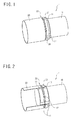
FIG. 1 is a perspective view illustrating a configuration in a certain embodiment of a joint structure; -
FIG. 2 is a partial cross-sectional view illustrating the configuration in the certain embodiment of the joint structure; -
FIG. 3 is a partial cross-sectional view of a main portion, illustrating the configuration in the certain embodiment of the joint structure; -
FIG. 4 is a partial cross-sectional view illustrating a configuration of a cylindrical member in the certain embodiment of the joint structure; -
FIG. 5 is a partial cross-sectional view illustrating a state before a first crimped portion forming step in the certain embodiment of a joining method of the joint structure; -
FIGs. 6A and 6B are partial cross-sectional views of the main portion in the first crimped portion forming step in the certain embodiment of the joining method of the joint structure, in whichFIG. 6A illustrates the state before the first crimped portion forming step, andFIG. 6B illustrates the state after the first crimped portion forming step; -
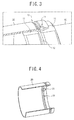
FIGs. 7A and 7B are perspective views illustrating states in the second crimped portion forming step in the certain embodiment of the joining method of the joint structure, in whichFIG. 7A illustrates the state before the second crimped portion forming step, andFIG. 7B illustrates the state after the second crimped portion forming step; -
FIG. 8 is a partial cross-sectional view of the main portion, illustrating a state after the second crimped portion forming step in the certain embodiment of the joining method of the joint structure; -
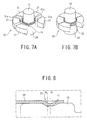
FIG. 9 is a cross-sectional view illustrating a configuration of a circumferential groove in another embodiment of the joint structure and the joining method; -
FIGs. 10A and 10B are perspective views illustrating states in the second crimped portion forming step in the other embodiment of the joint structure and the joining method, in whichFIG. 10A illustrates the state before the second crimped portion forming step, andFIG. 10B illustrates the state after the second crimped portion forming step; -
FIGs. 11A to 11D are photographs of the cylindrical member in the other embodiment of the joint structure and the joining method, in whichFIGs . 11A to 11C are photographs of an outer diameter of the cylindrical member on which a projection is formed, with the advance of crimping by reducing the diameter, viewed from directly above, andFIG. 11D is a photograph of the state of the projection on the inner diameter side of the cylindrical member after the crimping by reducing the diameter; -
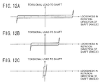
FIGs 12A to 12C are graphs illustrating a rotation stopping effect of the projection in the other embodiment of the joint structure and the joining method, a torque applied to the joined portion of the shaft member and the cylindrical member is illustrated on a vertical axis, and a relative angle between the shaft member and the cylindrical member is shown on a horizontal axis; -
FIG. 13 is a perspective view illustrating a configuration in a conventional joint structure; -
FIG. 14 is a partial cross-sectional view of the main portion illustrating the configuration in the conventional joint structure; and -
FIG. 15 is a partial cross-sectional view of the main portion illustrating the configuration in the conventional joint structure. - A description is made below of embodiments of a joint structure according to the present disclosure and a joining method thereof with reference to the drawings.
-
FIG. 1 is a perspective view illustrating a configuration in a certain embodiment of a joint structure according to the present disclosure. Furthermore,FIG. 2 is a partial cross-sectional view illustrating the configuration in the certain embodiment of the joint structure according to the present disclosure. Furthermore,FIG. 3 is a partial cross-sectional view of a main portion, illustrating the configuration in the certain embodiment of the joint structure according to the present disclosure. Furthermore,FIG. 4 is a partial cross-sectional view illustrating a configuration of a cylindrical member in the certain embodiment of the joint structure according to the present disclosure. It is to be noted thatFIG. 4 is expressed by omitting a shaft member fromFIG. 1 and FIG. 2 . - As illustrated in
FIG. 1 to FIG. 4 , a joint structure 1 of the present embodiment includes ashaft member 10 and acylindrical member 20 having an inner circumferential surface fitted to an outer circumferential surface of theshaft member 10. - Plural
axial grooves 11 are provided on a circumferential surface of theshaft member 10 in an axial direction. Furthermore, acircumferential groove 12 is provided over whole periphery of the circumferential surface of theshaft member 10. - The
cylindrical member 20 includes plural firstcrimped portions 21 crimped along the pluralaxial grooves 11, respectively, and a second crimpedportion 22 being fitted to theaxial grooves 11 and crimped along thecircumferential groove 12 of theshaft member 10 by reducing a diameter of an axially intermediate portion in a radial direction. In the present embodiment, the second crimpedportion 22 is provided over whole periphery of the circumferential surface of thecylindrical member 20. - That is, the first
crimped portions 21 are provided on intersections between theaxial grooves 11 and thecircumferential groove 12, and the second crimpedportion 22 is formed on the firstcrimped portions 21 by reducing the diameter of thecylindrical member 20. Specifically, as illustrated inFIG. 4 , a projection projecting from the inner circumferential surface of thecylindrical member 20 inwardly (hereinafter, also simply referred to as projection) is deformed by being crimped such that the side surface shape of theaxial groove 11 is transferred thereto. - Furthermore, as illustrated in
FIG. 4 , it is preferable that the first crimpedportion 21 have a shape projecting from the inner circumferential surface of thecylindrical member 20 as a spherical projection. - Furthermore, it is preferable that a diameter of a circle inscribed to the first
crimped portions 21 be set larger than the curvature radius of a bottom portion in a cross section in a circumferential direction of theaxial groove 11. - Next, a description is made of a joining method of the joint structure shown in
FIG. 1 to FIG. 4 . -
FIG. 5 is a partial cross-sectional view illustrating a state before a first crimped portion forming step in the certain embodiment of the joining method of the joint structure. Furthermore,FIGs. 6A and 6B are partial cross-sectional views of the main portion in the first crimped portion forming step in the certain embodiment of the joining method of the joint structure, in whichFIG. 6A illustrates the state before the first crimped portion forming step, andFIG. 6B illustrates the state after the first crimped portion forming step. - Furthermore,
FIGs. 7A and 7B are perspective views illustrating states in the second crimped portion forming step in the certain embodiment of the joining method of the joint structure, in whichFIG. 7A illustrates the state before the second crimped portion forming step, andFIG. 7B illustrates the state after the second crimped portion forming step. Furthermore,FIG. 8 is a partial cross-sectional view of the main portion illustrating a state after the second crimped portion forming step in the certain embodiment of the joining method of the joint structure. - The joining method of the joint structure of the present embodiment includes a provisional first crimped portion forming step of forming a provisional first
crimped portion 21A (seeFIG. 5 ) on thecylindrical member 20, and a first crimped portion forming step and a second crimped portion forming step after fitting theshaft member 10 and thecylindrical member 20 while bringing the outer surface of theshaft member 10 into contact with the inner surface of thecylindrical member 20 and engaging the provisional firstcrimped portion 21A with theaxial groove 11. - The provisional first crimped portion forming step is a step of forming plural projections on the inner circumferential surface of the
cylindrical member 20 such that these projections is engaged with the pluralaxial grooves 11 provided on theshaft member 10, respectively. It is to be noted that the provisional firstcrimped portions 21A are projections that are provided beforehand at positions where the firstcrimped portions 21 are to be provided on the outer circumferential surface of thecylindrical member 20 and project from the inner circumferential surface of thecylindrical member 20. That is, thecylindrical member 20 is fitted to theshaft member 10 while engaging the projects of the provisional firstcrimped portions 21A with theaxial grooves 11. - Furthermore, as illustrated in
FIGs. 6A and 6B , the first crimped portion forming step is a step of forming the firstcrimped portions 21 by further crimping the provisional firstcrimped portions 21A in a state in which the positions of the provisional firstcrimped portions 21A provided on thecylindrical member 20 in the provisional first crimped portion forming step are matched to a position where the second crimped portion is to be formed in the second crimped portion forming step described below. - Herein, a description is made of a relationship between the diameter of the circle inscribed to the projections of the provisional first crimped portions, projecting from the from the inner circumferential surface of the cylindrical member and the curvature radius of the bottom portion in the cross section in the circumferential direction of the axial grooves.
FIG. 14 is a cross-sectional view of the main portion illustrating a fitting state in a case in which the cylindrical member is crimped and fixed to the shaft member having axial grooves and the cross-sectional shape of the axial grooves in the circumferential direction is a single circular arc. - In the aspect illustrated in
FIG. 14 , since the projection comes into contact with the axial groove only at the tip of the projection (also at the bottom of the groove), there is no rigidity in the rotational direction. Thus, the function as a rotation stopper is not sufficient. This applies to not only the case in which the cross-sectional shape of the axial grooves is a single circular arc but also any case in which the cylindrical member is fitted to the shaft member at the tip of the projection. - Furthermore,
FIG. 15 is a cross-sectional view of the main portion illustrating a fitting state in a case in which the cylindrical member is crimped when the diameter of the circle inscribed to the projections of the provisional first crimped portions, projecting from the inner circumferential surface of the cylindrical member is substantially equal to the curvature radius of the bottom portion in the cross section in the circumferential direction of the axial grooves. - In the aspect illustrated in
FIG. 15 , the rigidity in the rotational direction can be obtained, however, the shoulder portion of the axial groove is more likely to damage the projection due to a phase shift in assembling. - Furthermore, when the projection is formed on the
cylindrical member 20 by deformation processing, springback may result in a shear drop at the foot of the projection. In order to avoid these problems, it is necessary to provide a grinding undercut at the shoulder portion of the axial groove, and thus, the fitting depth between the axial groove and the projection becomes shallower. - Therefore, in the present embodiment, the diameter of the circle inscribed to the projections of the provisional first
crimped portions 21A provided on thecylindrical member 20 beforehand, projecting from the inner circumferential surface of thecylindrical member 20 is set lager than the curvature radius of the bottom portion in the cross section in the circumferential direction of theaxial grooves 11 of theshaft member 10. That is, in the state illustrated inFIG. 6A (before the first crimped portion forming step), there is a gap between the projection of the provisional firstcrimped portion 21A provided on thecylindrical member 20 beforehand, projecting from the inner circumferential surface of thecylindrical member 20 and the axial groove. Therefore, theaxial groove 11 does not scrape off the projection of the provisional firstcrimped portion 21A in an assembling step. Furthermore, as the projection does not come into contact with theshaft member 10, the working accuracy of the projection does not affect assembling accuracy. - Then, with the advance of crimping the provisional first
crimped portion 21A in the first crimped portion forming step, as illustrated inFIG. 6B , the projection projecting from inner circumferential surface of thecylindrical member 20 is deformed toward theaxial groove 11 to come into contact with theaxial groove 11. It is to be noted that the diameter of the circle inscribed to the projections of the firstcrimped portions 21, projecting from the inner
circumferential surface of thecylindrical member 20 is still lager than the curvature radius of the bottom portion in the cross section in the circumferential direction of theaxial grooves 11 also after the first crimped portion forming step. - By such a configuration, it is possible to stably ensure a rotation stopping function regardless of a dimensional relation between the projection and the
axial groove 11. - As illustrated in
FIGs. 7A and 7B , the second crimped portion forming step is a step of crimping thecylindrical member 20 along thecircumferential groove 12 of theshaft member 10 by reducing a diameter of an axially intermediate portion of thecylindrical member 20 in a radial direction by using adie 30, thecylindrical member 20 being fitted to theshaft member 10 to form the second crimpedportion 22. It is to be noted that, in the second crimped portion forming step, the second crimpedportion 22 is formed so as to be connected to the first crimped portion. - The
die 30 includes plural approximately fan-shaped dividedbodies 31 combined in the circumferential directions to form a circular ring-shape. Each dividedbody 31 has an inner circumferential surface having a shape capable of coming into contact with the outer diameter of thecylindrical member 20. The dividedbody 31, as illustrated inFIGs. 7A and 7B for example, has a shape obtained by dividing the circular ring-shapeddie 30 into six pieces. It is to be noted that, inFIGs . 7A and 7B , representation of one dividedbody 31 is omitted. - Each divided
body 31 has a protrudingportion 31a on the inner circumferential surface thereof for pushing thecylindrical member 20 to thecircumferential groove 12 to forming the second crimpedportion 22. - In the second crimped portion forming step, first, as illustrated in
FIG. 6A , thedie 30 is arranged to surround thecylindrical member 20 after the first crimped portion forming step on the outer circumferential surface side. - Next, as illustrated in
FIG. 6B , the respective dividedbody 31a are pushed in synchronization with one another by using an apparatus (not illustrated) of synchronizing the respective dividedbody 31a with one another so as to push the respective dividedbody 31a toward the axis line of thedie 30. As a result, the diameter of thecylindrical member 20 is reduced in the radial direction to form the second crimpedportion 22 which is connected to the firstcrimped portions 21 and crimped along thecircumferential groove 12. - Herein, in the second crimped portion forming step, as illustrated in
FIG. 8 , it is preferable that the positon O1 in the axis direction of the tip of the projection of the second crimpedportion 22, projecting from the inner circumferential surface of thecylindrical member 20 be set to be displaced from the position 02 of the lowest point of thecircumferential groove 12. This is because when the position O1 in the axis direction of the tip of the projection is located at the position 02 of the lowest point of thecircumferential groove 12, an engaging amount between theaxial groove 11 and the projection may become small, and thus, desired rigidity may be hardly obtained. On the other hand, when an offset amount between the projection and thecircumferential groove 12 is too large, deformation of the projection by crimping becomes insufficient, and thus the projection does not exhibit a function as a rotation stopper. - For these reasons, it is preferable to lay out the position O1 of the tip in the axis direction of the projection within a predetermined range on the side surface side of the
circumferential groove 12. - It is to be noted that, in
FIG. 8 , by laying out the projection not only as "the projection of the second crimpedportion 22" but also as a projection of the provisional firstcrimped portion 21A, and reducing the diameter of thecylindrical member 20 along thecircumferential groove 12, the first crimpedportion 21 and the second crimpedportion 22 which is connected to the first crimpedportion 21 and crimped along the first crimpedportion 21 can be formed at the same time. The step of performing the first crimped portion forming step and the second crimped portion forming step at the same time is referred to as a crimped portion forming step. -
FIG. 9 is a cross-sectional view illustrating a configuration of the circumferential groove in another embodiment of the joint structure and the joining method. Furthermore,FIGs. 10A and 10B are perspective views illustrating states in the second crimped portion forming step in the other embodiment of the joint structure and the joining method, in whichFIG. 10A illustrates the state before the second crimped portion forming step, andFIG. 10B illustrates the state after the second crimped portion forming step. It is to be noted that, in the description of the present embodiment, a description of a duplicate configuration with that of the above-mentioned embodiment is omitted. - As illustrated in
FIGs. 9, 10A, and 10B , in the present embodiment, theaxial grooves 11 of theshaft member 10 have a bathtub-shaped cross-section in the circumferential direction. Such a shape makes the projection come into contact with the both side surfaces of theaxial groove 11 to obtain rigidity in the rotational direction. It is to be noted that, as illustrated inFIGs. 9, 10A, and 10B , a flat portion is provided on the bottom portion of theaxial groove 11, and the both sides of the flat portion rise at 60 degrees. - Furthermore, the open width of the
axial groove 11 is designed to be wider than the width of the foot of the projection. Thus, the dimensional relation is designed such that the shoulder portion of theaxial groove 11 and the projection do not interfere with each other at the time of assembling. - Furthermore, it is preferable that the
axial groove 11 be worked by cold forging work, and that theshaft member 10 be formed by performing a machining process on the cold forged product. At this time, when the side surface of theaxial groove 11 linearly rises toward the outer diameter of theshaft member 10, burrs may be generated when the outer circumferential surface is machined and may come into contact with the projection. In order to avoid this, it is preferable that the both side surfaces of theaxial groove 11 have a shape that opens outward in the vicinity of the outer circumferential surface of theshaft member 10. - Herein, photographs of the
cylindrical member 20 of the present embodiment illustrated inFIGs. 9, 10A, and 10B are represented inFIGs. 11A to 11D. FIGs. 11A to 11C are photographs of the projection viewed from directly above on the outer diameter side of thecylindrical member 20. These photographs represent an aspect in which the crimping by reducing the diameter progresses in the order ofFIGs. 11A, 11B, and 11C . Furthermore,FIG. 11D is a photograph of the state of the projection on the inner diameter side of thecylindrical member 20 after the crimping by reducing the diameter. In the photograph, it can be confirmed that the side surface shape of theaxial groove 11 is transferred to the both side surface of the projection. As illustrated inFIGs. 11A to 11D , it is found that the contact between the projection and the side surface of theaxial groove 11 allows joining without looseness in the rotational direction. - Furthermore,
FIGs 12A to 12C are graphs illustrating a rotation stopping effect of the projection, in which a torque applied to the joined portion of theshaft member 10 and thecylindrical member 20 is illustrated on a vertical axis, and a relative angle between theshaft member 10 and thecylindrical member 20 is shown on a horizontal axis. It is to be noted that the rises of the torque at the both ends in each diagram indicate points where the torque rises since the projaction comes into contact with the side surface of theaxial groove 11. It is to be noted thatFIGs. 12A to 12C illustrate measurement results in the respective states illustrated inFIGs. 11A to 11C , respectively, and indicate the relationship between the progress of the crimping by reducing the diameter and the looseness in the rotational direction. As illustrated inFIGs. 12A to 12C , it can be confirmed that as the crimping by reducing the diameter progresses and the projection comes into contact with the side surface of theaxial groove 11, the looseness in the rotational direction becomes smaller. - As described above, according to the certain embodiment of the present disclosure, the first crimped portion formed on the
cylindrical member 20 is deformed to be pushed to theaxial groove 11 with the crimping of thecylindrical member 20 in the second crimped portion forming step, and given a function of the rotation stopper as a result. - Furthermore, in the configuration of the present embodiment, since the projection and the
axial groove 11 have a relationship in which there is completely a gap therebetween at the time of assembling, it is not need to worry about the scraping of the projection and an influence on the assembling accuracy described above. Furthermore, since the first crimped portion is provided on the intersection between theaxial groove 11 and thecircumferential groove 12, the projection is deformed toward theaxial groove 11 with crimping of thecylindrical member 20 by reducing the diameter. Thus, there is no gap between the projection and theaxial groove 11 after crimping (after the second crimped portion forming step), the projection exhibits a function as a rotation stopper. - Therefore, it is possible to provide a joint structure capable of suitably joining the shaft member and the cylindrical member which compose the joint structure, and to provide a joining method thereof.
- As above, the description has been made of the joint structure and the joining method thereof. However, the joint structure according to the present disclosure and the joining method thereof are not limited to the above-described embodiments, and are modifiable in various ways without departing from the spirit of the present invention. For example, detailed conditions such as the shapes and the numbers of the axial groove and the circumferential groove, and the shapes and the numbers of the first crimped portion and the second crimped portion are alterable within a range where the functions of the present invention are exhibited.
-
- 1
- joint structure
- 10
- shaft member
- 11
- axial groove
- 12
- circumferential groove
- 20
- cylindrical member
- 21
- first crimped portion (spherical projection)
- 22
- second crimped portion
Claims (10)
- A joint structure comprising:a shaft member; anda cylindrical member, an inner surface of which is fitted to an outer surface of the shaft member, the cylindrical member including:a plurality of first crimped portions which are crimped along a plurality of axial grooves provided in an axial direction of the shaft member, respectively; anda second crimped portion which fits the axial grooves and is crimped along a circumferential groove, the circumferential groove being provided on a circumferential surface of the shaft member by reducing a diameter of an axially intermediate portion of the cylindrical member in a radial direction.
- The joint structure according to claim 1, wherein each of the first crimped portions has a shape projecting from the inner circumferential surface of the cylindrical member as a spherical projection.
- The joint structure according to claim 2, wherein a position of a tip in the axis direction of the spherical projection is laid out within a predetermined range on a side surface side of the circumferential groove.
- The joint structure according to any one of claims 1 to 3, wherein a diameter of a circle inscribed to the first crimped portions is set lager in cross section than a curvature radius of a bottom portion in a circumferential direction of each of the plurality of axial grooves.
- The joint structure according to any one of claims 1 to 4, wherein the circumferential groove has a bathtub-shaped cross-section in the axial direction.
- A joining method of a joint structure, the joining method comprising:a provisional first crimped portion forming step for forming a plurality of projections on an inner circumferential surface of a cylindrical member such that the plurality of projections are engaged with a plurality of axial grooves provided on a shaft member, respectively;fitting the shaft member to the cylindrical member such that an outer surface of the shaft member comes into contact with the inner surface of the cylindrical member, and such that the projections on the inner circumferential surface of the cylindrical member engage with the plurality of axial grooves provided on the shaft member and a circumferential groove provided on a circumferential surface of the shaft member; anda crimped portion forming step for forming first crimped portions and a second crimped portion which is connected the first crimped portions and crimped along the circumferential groove at the same time by laying out a tip in an axis direction of each of the plurality of the projections of respective provisional first crimped portions within a predetermined range on a side surface side of the circumferential groove, and by reducing a diameter of the cylindrical member along the circumferential groove provided on the circumferential surface of the shaft member.
- A joining method of a joint structure, the joining method comprising:a provisional first crimped portion forming step for forming a plurality of projections on an inner circumferential surface of a cylindrical member such that the plurality of projections are engaged with a plurality of axial grooves provided on a shaft member, respectively;fitting the shaft member to the cylindrical member such that an outer surface of the shaft member comes into contact with the inner surface of the cylindrical member, and such that the plurality of axial grooves provided on the shaft member engage with the projections on the inner circumferential surface of the cylindrical member; anda first crimped portion forming step for forming first crimped portions by deforming provisional first crimped portions along the axial grooves of the shaft member; anda second crimped portion forming step for forming a second crimped portion which is connected the first crimped portions and crimped along a circumferential groove provided on a circumferential surface of the shaft member by reducing a diameter of an axially intermediate portion of the cylindrical member in a radial direction.
- The joining method of the joint structure according to claim 6 or 7, wherein each of the first crimped portions formed in the crimped portion forming step or the first crimped portion forming step has a shape projecting from the inner circumferential surface of the cylindrical member as a spherical projection.
- The joining method of the joint structure according to any one of claims 6 to 8, wherein a diameter of a circle inscribed to the first crimped portions is set lager in cross section than a curvature radius of a bottom portion in a circumferential direction of each of the plurality of axial grooves.
- The joining method of the joint structure according to any one of claims 6 to 9, wherein the circumferential groove has a bathtub-shaped cross-section in the axial direction.
Applications Claiming Priority (2)
| Application Number | Priority Date | Filing Date | Title |
|---|---|---|---|
| JP2013105499 | 2013-05-17 | ||
| PCT/JP2013/007481 WO2014184832A1 (en) | 2013-05-17 | 2013-12-19 | Joint structure, and joining method therefor |
Publications (3)
| Publication Number | Publication Date |
|---|---|
| EP2998632A1 true EP2998632A1 (en) | 2016-03-23 |
| EP2998632A4 EP2998632A4 (en) | 2017-05-10 |
| EP2998632B1 EP2998632B1 (en) | 2019-11-20 |
Family
ID=51897854
Family Applications (1)
| Application Number | Title | Priority Date | Filing Date |
|---|---|---|---|
| EP13884924.5A Active EP2998632B1 (en) | 2013-05-17 | 2013-12-19 | Joint structure and joining method therefor |
Country Status (6)
| Country | Link |
|---|---|
| US (1) | US10145420B2 (en) |
| EP (1) | EP2998632B1 (en) |
| JP (1) | JP6061027B2 (en) |
| CN (1) | CN104395663B (en) |
| BR (1) | BR112015028816B1 (en) |
| WO (1) | WO2014184832A1 (en) |
Cited By (1)
| Publication number | Priority date | Publication date | Assignee | Title |
|---|---|---|---|---|
| US10376944B2 (en) * | 2014-02-20 | 2019-08-13 | Olympus Corporation | Pipe joining body, treatment tool, and joining method |
Families Citing this family (6)
| Publication number | Priority date | Publication date | Assignee | Title |
|---|---|---|---|---|
| DE102015100261B4 (en) * | 2015-01-09 | 2018-06-07 | Benteler Automobiltechnik Gmbh | Support for a motor vehicle and method of manufacturing a support for a motor vehicle |
| JP6758704B2 (en) * | 2016-06-29 | 2020-09-23 | Apsジャパン株式会社 | A caulking assembly of a metal plate-shaped body and a columnar body, a manufacturing method thereof, and a manufacturing apparatus thereof. |
| JP6909080B2 (en) * | 2016-11-28 | 2021-07-28 | 株式会社山田製作所 | Thermo-valve manufacturing method and thermo-valve |
| CN106734651B (en) * | 2016-12-07 | 2019-05-14 | 贵州黎阳航空动力有限公司 | A kind of closing method of flow regulator bridge pipe |
| CN110355228A (en) * | 2018-04-10 | 2019-10-22 | 东莞市荣翘泰五金有限公司 | Eccentric connector and its forming method |
| US11761490B2 (en) * | 2021-02-26 | 2023-09-19 | Nissan North America, Inc. | Drive train connector assembly |
Family Cites Families (21)
| Publication number | Priority date | Publication date | Assignee | Title |
|---|---|---|---|---|
| US1703037A (en) * | 1926-05-27 | 1929-02-19 | Mannesmannrohrenwerke | Method of joining tubular members |
| US2650114A (en) * | 1950-02-17 | 1953-08-25 | Epstein Saul | Sheet metal pipe and fitting connection |
| US3642311A (en) * | 1969-05-09 | 1972-02-15 | Gulf Oil Corp | Torque-transmitting joint |
| JPS5155864A (en) * | 1974-11-09 | 1976-05-17 | Furukawa Aluminium | KANJOTAINOSETSUGOHOHO |
| US4561799A (en) * | 1982-02-08 | 1985-12-31 | Grumman Aerospace Corp. | Torque joint |
| US4513488A (en) * | 1982-02-08 | 1985-04-30 | Grumman Aerospace Corporation | Method of fabricating a torque joint |
| FR2528132B1 (en) * | 1982-06-03 | 1985-09-27 | Cegedur | DEVICE FOR ASSEMBLING A TUBE AND A SHEET MEMBER |
| JPS59100174U (en) * | 1982-12-24 | 1984-07-06 | 松下電器産業株式会社 | Connecting part of pipe-shaped member |
| JPS59212134A (en) * | 1983-05-18 | 1984-12-01 | Fuaiaaransu Kogyo Kk | Connecting method of oxygen lance |
| JPS60157029U (en) * | 1984-03-29 | 1985-10-19 | 富士通株式会社 | Caulk fastening parts |
| JPH0341186Y2 (en) | 1987-03-31 | 1991-08-29 | ||
| US4902048A (en) | 1987-03-31 | 1990-02-20 | Usui Kokusai Sangyo Kaisha Ltd. | Joint structure for jointing metal pipes at their ends |
| US4807351A (en) * | 1988-02-18 | 1989-02-28 | Asea Composites, Inc. | Method for attaching an end-fitting to a drive shaft tube |
| DE69711863T2 (en) * | 1996-04-30 | 2002-11-07 | B D Kendle Engineering Ltd | PIPE CONNECTION |
| US6015350A (en) * | 1997-12-03 | 2000-01-18 | Dana Corporation | Collapsible vehicle driveshaft |
| US6301975B1 (en) * | 1998-02-26 | 2001-10-16 | Nsk Ltd. | Torque sensor having improved reliability against thermal expansion and axial displacement of components |
| JP3307317B2 (en) | 1998-02-26 | 2002-07-24 | 日本精工株式会社 | Torque sensor |
| JP2001269740A (en) * | 2000-03-29 | 2001-10-02 | Tokai Rubber Ind Ltd | Metal rod and its manufacturing method |
| DE102008015028A1 (en) | 2008-03-19 | 2009-09-24 | Rauschnabel, Eberhard, Dr. | Massive hollow shafts e.g. drive shaft, connecting method, involves sliding connecting piece over profiled inner part, and completely or partially molding outer part in profile inner part by profiled tool or flexible reduction tool |
| CN201434163Y (en) * | 2009-01-21 | 2010-03-31 | 段少俊 | Pipeline connecting piece for stainless steel thin-walled pipe |
| JP2013525696A (en) * | 2010-04-05 | 2013-06-20 | アドバンスド ジョイニング テクノロジーズ,インク. | Riser member and manufacturing method thereof |
-
2013
- 2013-12-19 WO PCT/JP2013/007481 patent/WO2014184832A1/en active Application Filing
- 2013-12-19 BR BR112015028816-2A patent/BR112015028816B1/en active IP Right Grant
- 2013-12-19 CN CN201380003398.8A patent/CN104395663B/en not_active Expired - Fee Related
- 2013-12-19 EP EP13884924.5A patent/EP2998632B1/en active Active
- 2013-12-19 US US14/891,535 patent/US10145420B2/en active Active
- 2013-12-19 JP JP2015516759A patent/JP6061027B2/en active Active
Cited By (1)
| Publication number | Priority date | Publication date | Assignee | Title |
|---|---|---|---|---|
| US10376944B2 (en) * | 2014-02-20 | 2019-08-13 | Olympus Corporation | Pipe joining body, treatment tool, and joining method |
Also Published As
| Publication number | Publication date |
|---|---|
| JP6061027B2 (en) | 2017-01-18 |
| EP2998632B1 (en) | 2019-11-20 |
| BR112015028816A2 (en) | 2017-07-25 |
| CN104395663B (en) | 2016-05-11 |
| EP2998632A4 (en) | 2017-05-10 |
| WO2014184832A1 (en) | 2014-11-20 |
| JPWO2014184832A1 (en) | 2017-02-23 |
| US20160089711A1 (en) | 2016-03-31 |
| BR112015028816B1 (en) | 2020-12-08 |
| CN104395663A (en) | 2015-03-04 |
| US10145420B2 (en) | 2018-12-04 |
Similar Documents
| Publication | Publication Date | Title |
|---|---|---|
| EP2998632B1 (en) | Joint structure and joining method therefor | |
| JP6917377B2 (en) | Plug connector socket | |
| JP2008536075A (en) | Collar with end face for driveable wheel boss | |
| JP2013064502A (en) | Bearing cage | |
| KR102090351B1 (en) | Method for producing a connecting element for transmitting rotational movements and connecting element produced thereby | |
| EP2985503B1 (en) | Joining structure and joining method thereof | |
| EP3343734A1 (en) | Armature and manufacturing method for armature | |
| EP2937943A1 (en) | Socket contact | |
| CN107081362B (en) | Roller set and pipe element | |
| CN104868652A (en) | Motor and planetary gear assembly and method for connecting motor and planetary gear unit for producing motor and planetary gear assembly | |
| US10396607B2 (en) | Bus ring unit | |
| US10632517B2 (en) | Crimp structure, crimping method, and electronic device | |
| EP3043099B1 (en) | Sealing member for pipe connection comprising protrusions | |
| WO2016031644A1 (en) | Bearing device and method for manufacturing bearing device | |
| US9243702B2 (en) | Torque converter blade tab undercuts | |
| EP2840265A2 (en) | Retainer cap for shaft assembly | |
| JP6205508B2 (en) | Sliding bearing and manufacturing method of sliding bearing | |
| JP6318555B2 (en) | Bearing device and bearing device manufacturing method | |
| JP2017020606A (en) | Bearing device | |
| JP2009113183A (en) | Method of machining female spline | |
| JP2006346684A (en) | Infeed form rolling die, and screw shaft of ball screw mechanism | |
| JP5901950B2 (en) | Spline fitting structure | |
| JP6291832B2 (en) | Manufacturing method of universal joint | |
| JP5757188B2 (en) | Thin plate connection structure | |
| US20210285585A1 (en) | Mechanical orientation control heater hose assembly for quick connect |
Legal Events
| Date | Code | Title | Description |
|---|---|---|---|
| PUAI | Public reference made under article 153(3) epc to a published international application that has entered the european phase |
Free format text: ORIGINAL CODE: 0009012 |
|
| 17P | Request for examination filed |
Effective date: 20151109 |
|
| AK | Designated contracting states |
Kind code of ref document: A1 Designated state(s): AL AT BE BG CH CY CZ DE DK EE ES FI FR GB GR HR HU IE IS IT LI LT LU LV MC MK MT NL NO PL PT RO RS SE SI SK SM TR |
|
| AX | Request for extension of the european patent |
Extension state: BA ME |
|
| DAX | Request for extension of the european patent (deleted) | ||
| A4 | Supplementary search report drawn up and despatched |
Effective date: 20170412 |
|
| RIC1 | Information provided on ipc code assigned before grant |
Ipc: B21D 39/04 20060101ALI20170406BHEP Ipc: F16L 13/14 20060101AFI20170406BHEP |
|
| GRAP | Despatch of communication of intention to grant a patent |
Free format text: ORIGINAL CODE: EPIDOSNIGR1 |
|
| STAA | Information on the status of an ep patent application or granted ep patent |
Free format text: STATUS: GRANT OF PATENT IS INTENDED |
|
| INTG | Intention to grant announced |
Effective date: 20190621 |
|
| GRAS | Grant fee paid |
Free format text: ORIGINAL CODE: EPIDOSNIGR3 |
|
| GRAA | (expected) grant |
Free format text: ORIGINAL CODE: 0009210 |
|
| STAA | Information on the status of an ep patent application or granted ep patent |
Free format text: STATUS: THE PATENT HAS BEEN GRANTED |
|
| AK | Designated contracting states |
Kind code of ref document: B1 Designated state(s): AL AT BE BG CH CY CZ DE DK EE ES FI FR GB GR HR HU IE IS IT LI LT LU LV MC MK MT NL NO PL PT RO RS SE SI SK SM TR |
|
| REG | Reference to a national code |
Ref country code: GB Ref legal event code: FG4D |
|
| REG | Reference to a national code |
Ref country code: CH Ref legal event code: EP |
|
| REG | Reference to a national code |
Ref country code: IE Ref legal event code: FG4D |
|
| REG | Reference to a national code |
Ref country code: DE Ref legal event code: R096 Ref document number: 602013063240 Country of ref document: DE |
|
| REG | Reference to a national code |
Ref country code: AT Ref legal event code: REF Ref document number: 1204574 Country of ref document: AT Kind code of ref document: T Effective date: 20191215 |
|
| REG | Reference to a national code |
Ref country code: NL Ref legal event code: MP Effective date: 20191120 |
|
| REG | Reference to a national code |
Ref country code: LT Ref legal event code: MG4D |
|
| PG25 | Lapsed in a contracting state [announced via postgrant information from national office to epo] |
Ref country code: LV Free format text: LAPSE BECAUSE OF FAILURE TO SUBMIT A TRANSLATION OF THE DESCRIPTION OR TO PAY THE FEE WITHIN THE PRESCRIBED TIME-LIMIT Effective date: 20191120 Ref country code: FI Free format text: LAPSE BECAUSE OF FAILURE TO SUBMIT A TRANSLATION OF THE DESCRIPTION OR TO PAY THE FEE WITHIN THE PRESCRIBED TIME-LIMIT Effective date: 20191120 Ref country code: BG Free format text: LAPSE BECAUSE OF FAILURE TO SUBMIT A TRANSLATION OF THE DESCRIPTION OR TO PAY THE FEE WITHIN THE PRESCRIBED TIME-LIMIT Effective date: 20200220 Ref country code: SE Free format text: LAPSE BECAUSE OF FAILURE TO SUBMIT A TRANSLATION OF THE DESCRIPTION OR TO PAY THE FEE WITHIN THE PRESCRIBED TIME-LIMIT Effective date: 20191120 Ref country code: NO Free format text: LAPSE BECAUSE OF FAILURE TO SUBMIT A TRANSLATION OF THE DESCRIPTION OR TO PAY THE FEE WITHIN THE PRESCRIBED TIME-LIMIT Effective date: 20200220 Ref country code: LT Free format text: LAPSE BECAUSE OF FAILURE TO SUBMIT A TRANSLATION OF THE DESCRIPTION OR TO PAY THE FEE WITHIN THE PRESCRIBED TIME-LIMIT Effective date: 20191120 Ref country code: GR Free format text: LAPSE BECAUSE OF FAILURE TO SUBMIT A TRANSLATION OF THE DESCRIPTION OR TO PAY THE FEE WITHIN THE PRESCRIBED TIME-LIMIT Effective date: 20200221 Ref country code: NL Free format text: LAPSE BECAUSE OF FAILURE TO SUBMIT A TRANSLATION OF THE DESCRIPTION OR TO PAY THE FEE WITHIN THE PRESCRIBED TIME-LIMIT Effective date: 20191120 |
|
| PG25 | Lapsed in a contracting state [announced via postgrant information from national office to epo] |
Ref country code: HR Free format text: LAPSE BECAUSE OF FAILURE TO SUBMIT A TRANSLATION OF THE DESCRIPTION OR TO PAY THE FEE WITHIN THE PRESCRIBED TIME-LIMIT Effective date: 20191120 Ref country code: IS Free format text: LAPSE BECAUSE OF FAILURE TO SUBMIT A TRANSLATION OF THE DESCRIPTION OR TO PAY THE FEE WITHIN THE PRESCRIBED TIME-LIMIT Effective date: 20200320 Ref country code: RS Free format text: LAPSE BECAUSE OF FAILURE TO SUBMIT A TRANSLATION OF THE DESCRIPTION OR TO PAY THE FEE WITHIN THE PRESCRIBED TIME-LIMIT Effective date: 20191120 |
|
| PG25 | Lapsed in a contracting state [announced via postgrant information from national office to epo] |
Ref country code: AL Free format text: LAPSE BECAUSE OF FAILURE TO SUBMIT A TRANSLATION OF THE DESCRIPTION OR TO PAY THE FEE WITHIN THE PRESCRIBED TIME-LIMIT Effective date: 20191120 |
|
| PG25 | Lapsed in a contracting state [announced via postgrant information from national office to epo] |
Ref country code: PT Free format text: LAPSE BECAUSE OF FAILURE TO SUBMIT A TRANSLATION OF THE DESCRIPTION OR TO PAY THE FEE WITHIN THE PRESCRIBED TIME-LIMIT Effective date: 20200412 Ref country code: DK Free format text: LAPSE BECAUSE OF FAILURE TO SUBMIT A TRANSLATION OF THE DESCRIPTION OR TO PAY THE FEE WITHIN THE PRESCRIBED TIME-LIMIT Effective date: 20191120 Ref country code: CZ Free format text: LAPSE BECAUSE OF FAILURE TO SUBMIT A TRANSLATION OF THE DESCRIPTION OR TO PAY THE FEE WITHIN THE PRESCRIBED TIME-LIMIT Effective date: 20191120 Ref country code: RO Free format text: LAPSE BECAUSE OF FAILURE TO SUBMIT A TRANSLATION OF THE DESCRIPTION OR TO PAY THE FEE WITHIN THE PRESCRIBED TIME-LIMIT Effective date: 20191120 Ref country code: EE Free format text: LAPSE BECAUSE OF FAILURE TO SUBMIT A TRANSLATION OF THE DESCRIPTION OR TO PAY THE FEE WITHIN THE PRESCRIBED TIME-LIMIT Effective date: 20191120 Ref country code: ES Free format text: LAPSE BECAUSE OF FAILURE TO SUBMIT A TRANSLATION OF THE DESCRIPTION OR TO PAY THE FEE WITHIN THE PRESCRIBED TIME-LIMIT Effective date: 20191120 |
|
| REG | Reference to a national code |
Ref country code: CH Ref legal event code: PL |
|
| REG | Reference to a national code |
Ref country code: AT Ref legal event code: MK05 Ref document number: 1204574 Country of ref document: AT Kind code of ref document: T Effective date: 20191120 |
|
| REG | Reference to a national code |
Ref country code: DE Ref legal event code: R097 Ref document number: 602013063240 Country of ref document: DE |
|
| REG | Reference to a national code |
Ref country code: BE Ref legal event code: MM Effective date: 20191231 |
|
| PG25 | Lapsed in a contracting state [announced via postgrant information from national office to epo] |
Ref country code: SM Free format text: LAPSE BECAUSE OF FAILURE TO SUBMIT A TRANSLATION OF THE DESCRIPTION OR TO PAY THE FEE WITHIN THE PRESCRIBED TIME-LIMIT Effective date: 20191120 Ref country code: SK Free format text: LAPSE BECAUSE OF FAILURE TO SUBMIT A TRANSLATION OF THE DESCRIPTION OR TO PAY THE FEE WITHIN THE PRESCRIBED TIME-LIMIT Effective date: 20191120 Ref country code: MC Free format text: LAPSE BECAUSE OF FAILURE TO SUBMIT A TRANSLATION OF THE DESCRIPTION OR TO PAY THE FEE WITHIN THE PRESCRIBED TIME-LIMIT Effective date: 20191120 |
|
| PLBE | No opposition filed within time limit |
Free format text: ORIGINAL CODE: 0009261 |
|
| STAA | Information on the status of an ep patent application or granted ep patent |
Free format text: STATUS: NO OPPOSITION FILED WITHIN TIME LIMIT |
|
| 26N | No opposition filed |
Effective date: 20200821 |
|
| PG25 | Lapsed in a contracting state [announced via postgrant information from national office to epo] |
Ref country code: LU Free format text: LAPSE BECAUSE OF NON-PAYMENT OF DUE FEES Effective date: 20191219 Ref country code: IE Free format text: LAPSE BECAUSE OF NON-PAYMENT OF DUE FEES Effective date: 20191219 |
|
| PG25 | Lapsed in a contracting state [announced via postgrant information from national office to epo] |
Ref country code: CH Free format text: LAPSE BECAUSE OF NON-PAYMENT OF DUE FEES Effective date: 20191231 Ref country code: LI Free format text: LAPSE BECAUSE OF NON-PAYMENT OF DUE FEES Effective date: 20191231 Ref country code: AT Free format text: LAPSE BECAUSE OF FAILURE TO SUBMIT A TRANSLATION OF THE DESCRIPTION OR TO PAY THE FEE WITHIN THE PRESCRIBED TIME-LIMIT Effective date: 20191120 Ref country code: PL Free format text: LAPSE BECAUSE OF FAILURE TO SUBMIT A TRANSLATION OF THE DESCRIPTION OR TO PAY THE FEE WITHIN THE PRESCRIBED TIME-LIMIT Effective date: 20191120 Ref country code: SI Free format text: LAPSE BECAUSE OF FAILURE TO SUBMIT A TRANSLATION OF THE DESCRIPTION OR TO PAY THE FEE WITHIN THE PRESCRIBED TIME-LIMIT Effective date: 20191120 Ref country code: BE Free format text: LAPSE BECAUSE OF NON-PAYMENT OF DUE FEES Effective date: 20191231 |
|
| PG25 | Lapsed in a contracting state [announced via postgrant information from national office to epo] |
Ref country code: IT Free format text: LAPSE BECAUSE OF FAILURE TO SUBMIT A TRANSLATION OF THE DESCRIPTION OR TO PAY THE FEE WITHIN THE PRESCRIBED TIME-LIMIT Effective date: 20191120 |
|
| PG25 | Lapsed in a contracting state [announced via postgrant information from national office to epo] |
Ref country code: CY Free format text: LAPSE BECAUSE OF FAILURE TO SUBMIT A TRANSLATION OF THE DESCRIPTION OR TO PAY THE FEE WITHIN THE PRESCRIBED TIME-LIMIT Effective date: 20191120 |
|
| PG25 | Lapsed in a contracting state [announced via postgrant information from national office to epo] |
Ref country code: MT Free format text: LAPSE BECAUSE OF FAILURE TO SUBMIT A TRANSLATION OF THE DESCRIPTION OR TO PAY THE FEE WITHIN THE PRESCRIBED TIME-LIMIT Effective date: 20191120 Ref country code: HU Free format text: LAPSE BECAUSE OF FAILURE TO SUBMIT A TRANSLATION OF THE DESCRIPTION OR TO PAY THE FEE WITHIN THE PRESCRIBED TIME-LIMIT; INVALID AB INITIO Effective date: 20131219 |
|
| PGFP | Annual fee paid to national office [announced via postgrant information from national office to epo] |
Ref country code: GB Payment date: 20211028 Year of fee payment: 9 Ref country code: FR Payment date: 20211115 Year of fee payment: 9 |
|
| PG25 | Lapsed in a contracting state [announced via postgrant information from national office to epo] |
Ref country code: TR Free format text: LAPSE BECAUSE OF FAILURE TO SUBMIT A TRANSLATION OF THE DESCRIPTION OR TO PAY THE FEE WITHIN THE PRESCRIBED TIME-LIMIT Effective date: 20191120 |
|
| PG25 | Lapsed in a contracting state [announced via postgrant information from national office to epo] |
Ref country code: MK Free format text: LAPSE BECAUSE OF FAILURE TO SUBMIT A TRANSLATION OF THE DESCRIPTION OR TO PAY THE FEE WITHIN THE PRESCRIBED TIME-LIMIT Effective date: 20191120 |
|
| GBPC | Gb: european patent ceased through non-payment of renewal fee |
Effective date: 20221219 |
|
| PG25 | Lapsed in a contracting state [announced via postgrant information from national office to epo] |
Ref country code: GB Free format text: LAPSE BECAUSE OF NON-PAYMENT OF DUE FEES Effective date: 20221219 |
|
| PG25 | Lapsed in a contracting state [announced via postgrant information from national office to epo] |
Ref country code: FR Free format text: LAPSE BECAUSE OF NON-PAYMENT OF DUE FEES Effective date: 20221231 |
|
| PGFP | Annual fee paid to national office [announced via postgrant information from national office to epo] |
Ref country code: DE Payment date: 20231031 Year of fee payment: 11 |