EP2998556A1 - Variable nozzle for aircraft gas turbine engine - Google Patents
Variable nozzle for aircraft gas turbine engine Download PDFInfo
- Publication number
- EP2998556A1 EP2998556A1 EP14797266.5A EP14797266A EP2998556A1 EP 2998556 A1 EP2998556 A1 EP 2998556A1 EP 14797266 A EP14797266 A EP 14797266A EP 2998556 A1 EP2998556 A1 EP 2998556A1
- Authority
- EP
- European Patent Office
- Prior art keywords
- primary
- flaps
- flow path
- variable nozzle
- sections
- Prior art date
- Legal status (The legal status is an assumption and is not a legal conclusion. Google has not performed a legal analysis and makes no representation as to the accuracy of the status listed.)
- Granted
Links
Images




Classifications
-
- F—MECHANICAL ENGINEERING; LIGHTING; HEATING; WEAPONS; BLASTING
- F01—MACHINES OR ENGINES IN GENERAL; ENGINE PLANTS IN GENERAL; STEAM ENGINES
- F01D—NON-POSITIVE DISPLACEMENT MACHINES OR ENGINES, e.g. STEAM TURBINES
- F01D17/00—Regulating or controlling by varying flow
- F01D17/10—Final actuators
- F01D17/12—Final actuators arranged in stator parts
- F01D17/14—Final actuators arranged in stator parts varying effective cross-sectional area of nozzles or guide conduits
- F01D17/16—Final actuators arranged in stator parts varying effective cross-sectional area of nozzles or guide conduits by means of nozzle vanes
-
- F—MECHANICAL ENGINEERING; LIGHTING; HEATING; WEAPONS; BLASTING
- F02—COMBUSTION ENGINES; HOT-GAS OR COMBUSTION-PRODUCT ENGINE PLANTS
- F02K—JET-PROPULSION PLANTS
- F02K1/00—Plants characterised by the form or arrangement of the jet pipe or nozzle; Jet pipes or nozzles peculiar thereto
- F02K1/06—Varying effective area of jet pipe or nozzle
- F02K1/12—Varying effective area of jet pipe or nozzle by means of pivoted flaps
- F02K1/1223—Varying effective area of jet pipe or nozzle by means of pivoted flaps of two series of flaps, the upstream series having its flaps hinged at their upstream ends on a fixed structure and the downstream series having its flaps hinged at their upstream ends on the downstream ends of the flaps of the upstream series
-
- F—MECHANICAL ENGINEERING; LIGHTING; HEATING; WEAPONS; BLASTING
- F01—MACHINES OR ENGINES IN GENERAL; ENGINE PLANTS IN GENERAL; STEAM ENGINES
- F01D—NON-POSITIVE DISPLACEMENT MACHINES OR ENGINES, e.g. STEAM TURBINES
- F01D11/00—Preventing or minimising internal leakage of working-fluid, e.g. between stages
- F01D11/005—Sealing means between non relatively rotating elements
-
- F—MECHANICAL ENGINEERING; LIGHTING; HEATING; WEAPONS; BLASTING
- F01—MACHINES OR ENGINES IN GENERAL; ENGINE PLANTS IN GENERAL; STEAM ENGINES
- F01D—NON-POSITIVE DISPLACEMENT MACHINES OR ENGINES, e.g. STEAM TURBINES
- F01D25/00—Component parts, details, or accessories, not provided for in, or of interest apart from, other groups
- F01D25/30—Exhaust heads, chambers, or the like
-
- F—MECHANICAL ENGINEERING; LIGHTING; HEATING; WEAPONS; BLASTING
- F01—MACHINES OR ENGINES IN GENERAL; ENGINE PLANTS IN GENERAL; STEAM ENGINES
- F01D—NON-POSITIVE DISPLACEMENT MACHINES OR ENGINES, e.g. STEAM TURBINES
- F01D9/00—Stators
- F01D9/02—Nozzles; Nozzle boxes; Stator blades; Guide conduits, e.g. individual nozzles
-
- F—MECHANICAL ENGINEERING; LIGHTING; HEATING; WEAPONS; BLASTING
- F05—INDEXING SCHEMES RELATING TO ENGINES OR PUMPS IN VARIOUS SUBCLASSES OF CLASSES F01-F04
- F05D—INDEXING SCHEME FOR ASPECTS RELATING TO NON-POSITIVE-DISPLACEMENT MACHINES OR ENGINES, GAS-TURBINES OR JET-PROPULSION PLANTS
- F05D2220/00—Application
- F05D2220/30—Application in turbines
- F05D2220/32—Application in turbines in gas turbines
-
- F—MECHANICAL ENGINEERING; LIGHTING; HEATING; WEAPONS; BLASTING
- F05—INDEXING SCHEMES RELATING TO ENGINES OR PUMPS IN VARIOUS SUBCLASSES OF CLASSES F01-F04
- F05D—INDEXING SCHEME FOR ASPECTS RELATING TO NON-POSITIVE-DISPLACEMENT MACHINES OR ENGINES, GAS-TURBINES OR JET-PROPULSION PLANTS
- F05D2240/00—Components
- F05D2240/10—Stators
- F05D2240/12—Fluid guiding means, e.g. vanes
- F05D2240/128—Nozzles
-
- F—MECHANICAL ENGINEERING; LIGHTING; HEATING; WEAPONS; BLASTING
- F05—INDEXING SCHEMES RELATING TO ENGINES OR PUMPS IN VARIOUS SUBCLASSES OF CLASSES F01-F04
- F05D—INDEXING SCHEME FOR ASPECTS RELATING TO NON-POSITIVE-DISPLACEMENT MACHINES OR ENGINES, GAS-TURBINES OR JET-PROPULSION PLANTS
- F05D2240/00—Components
- F05D2240/55—Seals
Definitions
- the present invention relates to a variable nozzle for an aeronautic gas turbine engine and in particular relates to a variable nozzle capable of reducing loss in thrust thereof.
- An exhaust nozzle of an aeronautic gas turbine engine has a function of rectifying and ejecting exhaust gas rearward and, as well, a function of regulating its flow velocity.
- a so-called convergent nozzle that converges toward the downstream direction in order to increase the velocity of the exhaust gas flow.
- convergent-divergent nozzle that once converges the exhaust gas flow and thereafter, downstream of a throat, expands the flow.
- a convergent-divergent nozzle may be constructed as a variable nozzle that variates the aperture areas of the throat and the exhaust exit respectively in order to optimize its efficiency over a wide range of speed.
- the Patent Literatures 1 through 4 disclose related arts of variable nozzles.
- Variable nozzles require extremely high thermal resistance as they are directly exposed to high-temperature exhaust gas. Materials that can meet such a requirement of thermal resistance are, in general, poorly workable and are therefore available only for producing members with simple shapes such as flat panels. Thus, generally, a plurality of flaps and a plurality of seals, respectively formed into flat shapes, are combined to produce a variable nozzle. Experts frequently carry out numerical analysis of flow fields of exhaust gas to determine ideal flow path shapes and then determine dimensions and arrangement of flat flaps and flat seals so as to approximate these ideal flow path shapes.
- the present inventors have studied anew numerical analysis based on flat shapes and thereby reached the present invention.
- a variable nozzle which is used for ejecting exhaust gas of an aeronautic gas turbine engine along its axis from a fore end toward an aft end, is comprised of: an exhaust duct vectoring a flow of the exhaust gas to the aft end; a plurality of primary flaps arranged to define a primary flow path converging toward the aft end, each of the primary flaps being swingably pivoted on the exhaust duct to regulate a degree of opening the primary flow path and including a first section and a second section forming an angle axially outward relative to the first section; and a plurality of secondary flaps arranged to define a secondary flow path in communication with the primary flow path, the secondary flow path being capable of divergent toward the aft end, the secondary flaps being respectively swingably pivoted on the second sections of the primary flaps to regulate a degree of opening the secondary flow path.
- each primary flap has two sections having distinct angles, shock waves by angular flexures between the primary flaps and the secondary flaps are suppressed, thereby reducing loss in thrust.
- FIG. 1 is a perspective view of a variable nozzle 1 for an aeronautic gas turbine engine according to the present embodiment, which is viewed from its aft end.
- an outer flap 8 covering primary flaps 5 and secondary flaps 7 is drawn to be partly cut out and also linkages 13 for driving the primary flaps 7 are not drawn in FIG. 1 .
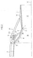
- FIG. 2 is a longitudinal sectional view showing an exhaust duct 3, the primary flap 5, the secondary flap 7, a ring structure 11 for driving the primary flap 5, and the linkage 13 for driving the primary flap 7 of the variable nozzle 1.
- variable nozzle 1 is in general comprised of the exhaust duct 3, the plurality of primary flaps 5, and the plurality of secondary flaps 7.
- the exhaust duct 3 is in fluid communication with a rear end of the main body of the engine and vectors its exhaust in the direction from the fore end to the aft end along an axis X.
- To the rear end of the exhaust duct 3 connected is the plurality of primary flaps 5 respectively and further to respective rear ends thereof connected is the plurality of secondary flaps 7. These flaps are arranged circumferentially to define a flow path for the exhaust gas flow.
- Respective gaps among the primary flaps 5 are blocked by primary seals 5a that get in contact with, and follow movements of, these primary flaps 5.
- Respective gaps among the secondary flaps 7 are blocked by secondary seals 7a in a similar way. The exhaust gas flow therein is thereby prevented from leaking out and flows along the axis X toward the exit of the nozzle.
- the plurality of primary flaps 5 and the plurality of primary seals 5a are arranged circumferentially to define a primary flow path 15.
- the primary seals 5a are in FIG. 3A hidden behind the primary flaps 5 because this drawing shows a state where the variable nozzle 1 is narrowed, it could be possible that they are exposed even in the narrowed state. Or, the plurality of primary seals 5a may be almost always exposed inward.
- Each primary flap 5 is, at its front end, pivoted on the exhaust duct 3 by means of a joint 51, thereby being capable of regulating its degree of opening.
- Each primary flap 5 is comprised of a first section 53 at its front, and a second section 55 unitarily continuous to the first section 53.
- the first section 53 and the second section 55 are respectively flat, and the second section 55, at a flexure section B, forms an angle radially outward (in a direction where the convergence is loosed or changed into a divergence) relative to the first section 53.
- Each primary seal 5a may be constructed in a similar way and is similarly pivoted on the exhaust duct 3.
- the plurality of secondary flaps 7 and the plurality of secondary seals 7a are arranged circumferentially to define a secondary flow path 17, which is in fluid communication with the primary flow path 15.
- Each secondary flap 7 is in general of a flat shape, and is pivoted on the second section 55 of the primary flap 5 by means of a joint 71, thereby being capable of regulating its degree of opening.
- Each secondary seal 7a may be constructed in a similar way and is similarly pivoted on each primary seal 5a.
- An exhaust gas flow J0 is forced to converge during passing through the primary flow path 15, thereby being compressed, and in exchange has a rise in temperature.
- the length of the primary flow path 15 is so determined that the exhaust gas flow J0 at a throat T comes to be about the sonic speed.
- the exhaust gas flow J0 in the secondary flow path 17 adiabatically expands and thereby accelerates further, thereby being capable of flowing beyond the sonic speed.
- the boundary between the primary flaps 5 and the secondary flaps 7 functions as the throat T as the narrowest section in the flow path. Further, as described later in more detail, the flexures of the primary flaps 5 can function as another throat depending on the degrees of opening the primary flaps 5 and the secondary flaps 7. The present disclosure will often refer this flexure section B as a pre-throat.
- the exhaust gas flow J0 is bent at the flexure section B and further bent at the throat T.
- both the first section 53 and the second section 55 are formed to be flat over the full width thereof but the flatness may not span the full width.
- the first section 53 and the second section 55 may be put between a pair of slopes S.
- the flexure section B in this example may be narrower than that in the above-described example, the effect of vectoring the exhaust gas flow J0 is similar.
- the pair of slopes S may be mutually in contact at the flexure section B. While the flexure section B in this example is a vertex of the first section 53, the second section 55, and the pair of slopes S, the effect of vectoring the exhaust gas flow J0 is similar.
- the primary seals 5a in the examples shown in FIG. 3B and 3C may be formed to be flat. As bases of the pair of slopes S are linear, when the variable nozzle 1 is made opened or closed, the seals 5a can be steadily made close contact with the flat primary flaps 5.
- variable nozzle 1 is comprised of any proper driver means so as to regulate the degrees of opening the primary flaps 5 and the secondary flaps 7.
- driver means is for example comprised of an actuator 9, the ring structure 11 and the linkage 13.
- the actuator 9 is for example a hydraulically driven piston, and a plunger extended from the piston is coupled with the ring structure 11 to drive it back and forth.
- the ring structure 11 is so disposed as to make its internal surface slide on the back of the primary flap 5, and is preferably comprised of a roller 11R to allow smooth slide.
- the plunger coupled with the ring structure 11 is not in sight in FIG. 2 because the plunger runs in a plane different from the plane shown in the drawing.
- Each primary flap 5 is, corresponding to the ring structure 11, comprised of a cam follower structure 57, which has a curved shape like as an arc. As the ring structure 11 moves back or forth on the cam follower structure 57, the primary flap 5 correspondingly swings around the joint 51. Response by the primary flap 5 to the back and forth motion of the ring structure 11 depends considerably on the shape of the cam follower structure 57.
- the linkage 13 is driven in conjunction with, or independently from, the ring structure 11. More specifically, another actuator independent of the actuator 9 may be provided for the purpose of driving the linkage 13.
- the tip of the linkage 13 is rotatably coupled with a backing structure 73 of the primary flap 7. As the linkage 13 moves back or forth, the secondary flap 7 swings around the joint 71.
- the driver means as described above are no more than examples but may be replaced with any other proper constitutions.
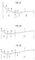
- the degrees of opening the primary flap 5 and the secondary flap 7 may be changed, in a state where the degrees are relatively small, they may fall in a position relation shown in FIG. 4A . More specifically, the primary flow path 15 defined by the primary flaps 5, as a whole, converges toward the aft end. An angle alpha between the first section 53 and the second section 55, even in this state, has a sufficient angle to make the second section 55 converge toward the aft end. An angle theta between the primary flap 5 and the secondary flap 7, also even in this state, is sufficiently small to make the secondary flow path 17 defined by the secondary flap 7 converge toward the aft end.
- both the convergent flap and the divergent flap are flat, its throat therebetween, slightly differently from such an ideal shape, makes an angular curve. This difference consequently generates a shock wave structure in the exhaust gas flow downstream of the throat, which causes non-negligible loss in thrust. This effect will be later described in more detail.
- the angle alpha may be so determined as to allow the primary flap 5 and the secondary flap 7 to fall in a position relation shown in FIG. 4B in the course of opening both of them to the greater degrees. More specifically, the angle alpha may be so determined that, at least when the primary flow path 15 is opened at the maximum degree, the second section 55 of the primary flap 5 can be parallel to the axis X or slightly divergent.
- the flexure section B on behalf of the boundary between the primary flap 5 and the secondary flap 7, functions as a throat T'.
- the exhaust gas flow J1 is forced to converge until passage through the throat T' and thereafter expands to reach the ultrasonic speed.
- the angle alpha may be so determined as to allow the flaps to fall in a position relation shown in FIG. 4C when the primary flap 5 is opened sufficiently wide. More specifically, the angle alpha may be so determined that, at least when the primary flow path 15 is opened at the maximum degree, the second section 55 of the primary flap 5 can be substantially in line with the secondary flap 7. As the exhaust gas flow J2 can, after passing through the throat T', linearly expand as shown in the arrow J2, loss in thrust is unlikely to occur.
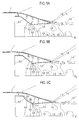
- FIGs. 5A through 5C show examples of results of CFD analyses based on dimensions and flow rates of a real engine, where FIG. 5A is a result about an ideally shaped nozzle Id that is consistent with an ideal shape determined by a numerical analysis, where FIG. 5B is a result about a nozzle C in which a combination of flat flaps approximates the ideal shape, and where FIG. 5C is a result about the variable nozzle 1 of the present embodiment.
- flow speeds at respective regions are shown by isokinetic contours and numerals in the drawings represent Mach numbers.
- the exhaust duct 3 the primary flap 5i and the secondary flap 7i are respectively generally flat but respective boundaries among them make continuously transient curves.
- the throat Ti makes a smooth curve.
- the flow speeds are relatively low at the depth of the exhaust duct 3i.
- the flow thereafter expands by the divergent secondary flap 7i to exceed the sonic speed, and then reaches about Mach 1.5 around the exit of the nozzle.
- both the primary flap 5c and the secondary flap 7c are flat and therefore boundaries among the exhaust duct 3c, the primary flap 5c and the secondary flap 7c make angular curves. Also in results of this case, a flow speed about Mach 1 around the throat Tc and a flow speed about Mach 1.5 around the exit of the nozzle are acknowledged.
- FIG. 5A it is particularly emphasized that a region over Mach 1.8, somewhat upstream of the exit of the nozzle along the axis Xc, becomes prominent. Although it may not be well comprehensible from the drawing, the fastest point in this region reaches about Mach 2. More specifically, the shock wave structure will develop well according to the prior art.
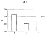
- thrust coefficients Ct (1 if no loss) obtained by these CFD analyses are compared in FIG. 6 . While the thrust coefficient Ct of the nozzle C constituted of flat panels is about 0.985, the variable nozzle 1 of the present embodiment gives a higher Ct of 0.991. This is comparable with that of the ideal nozzle Id and therefore it is understood that the present embodiment produces a relatively small thrust loss.
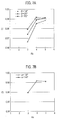
- FIG. 7A is a graph showing influences of angles theta between the second section 55 of the primary flap 5 and the secondary flap 7 on thrust coefficients Ct, on the basis of a case where the angle alpha between the first section 53 and the second section 55 of the primary flap 5 is set to be 132 degrees in the present embodiment.
- the horizontal axis represents a nozzle compression ratio Rc as a value of an aperture area of the primary flap 5 at the most upstream section divided by an aperture area of the throat T.
- Rc nozzle compression ratio
- Increase in nozzle compression ratio Rc results in increase in thrust coefficient Ct (small thrust loss) if the nozzle compression ratio Rc is in the range of 3 to 4. If the nozzle compression ratio Rc is in the range of 4 to 5, increase in nozzle compression ratio Rc results in increase in thrust coefficient Ct if the angle theta is in the range of 138 degrees to 151 degrees, but this effect may be saturated if the angle theta is any angle over 151 degrees, at least 162 degrees. On the basis of these results, the angle theta is preferably equal to or more than 138 degrees, and more preferably equal to or more than 151 degrees and equal to or less than 162 degrees.
- FIG. 7B is a graph showing influences of angles alpha between the first section 53 and the second section 55 of the primary flap 5 on thrust coefficients Ct as the angle theta between the second section 55 of the primary flap 5 and the secondary flap 7 is fixed to be 162 degrees.
- the angle alpha is preferably less than 180 degrees and at least within any angle range including the range of 132 degrees to 148 degrees.
- FIG. 8 is a graph comparing the flow rate coefficients Cd, where the horizontal axis represents a nozzle pressure ratio (a ratio of a nozzle internal pressure to the atmospheric pressure) npr. Solid circles represent values of the variable nozzle of the present embodiment and solid rectangles represent values of a variable nozzle without a pre-throat. In any nozzle compression ratios aside from about 1.5, the variable nozzle of the present embodiment is higher in flow rate coefficient Cd and its difference delta-Cd is about 0.012. More specifically, the flow rate is expected to be increased by about 1.2 %.
- FIG. 9 is a graph of a thrust ratio Rt of a thrust by the variable nozzle of the present embodiment to the variable nozzle without the pre-throat, where the horizontal axis similarly represents a nozzle pressure ratio npr.
- the variable nozzle of the present embodiment produces higher thrust and increase in thrust is nearly 2 %.
- a variable nozzle for an aeronautic gas turbine engine which can suppress thrust loss, is provided.
Landscapes
- Engineering & Computer Science (AREA)
- Mechanical Engineering (AREA)
- General Engineering & Computer Science (AREA)
- Chemical & Material Sciences (AREA)
- Combustion & Propulsion (AREA)
- Supercharger (AREA)
- Control Of Turbines (AREA)
Abstract
Description
- The present invention relates to a variable nozzle for an aeronautic gas turbine engine and in particular relates to a variable nozzle capable of reducing loss in thrust thereof.
- An exhaust nozzle of an aeronautic gas turbine engine has a function of rectifying and ejecting exhaust gas rearward and, as well, a function of regulating its flow velocity. In a case where the gas turbine engine is operated only within a subsonic speed range, usually used is a so-called convergent nozzle that converges toward the downstream direction in order to increase the velocity of the exhaust gas flow. In a case where the gas turbine engine is also operated beyond the sonic speed, frequently used is a so-called convergent-divergent nozzle that once converges the exhaust gas flow and thereafter, downstream of a throat, expands the flow. A convergent-divergent nozzle may be constructed as a variable nozzle that variates the aperture areas of the throat and the exhaust exit respectively in order to optimize its efficiency over a wide range of speed. The
Patent Literatures 1 through 4 disclose related arts of variable nozzles. - Variable nozzles require extremely high thermal resistance as they are directly exposed to high-temperature exhaust gas. Materials that can meet such a requirement of thermal resistance are, in general, poorly workable and are therefore available only for producing members with simple shapes such as flat panels. Thus, generally, a plurality of flaps and a plurality of seals, respectively formed into flat shapes, are combined to produce a variable nozzle. Experts frequently carry out numerical analysis of flow fields of exhaust gas to determine ideal flow path shapes and then determine dimensions and arrangement of flat flaps and flat seals so as to approximate these ideal flow path shapes.
-
- PTL 1: Japanese Patent Application Laid-open No.
H05-141310 - PTL 2: Japanese Patent Application Laid-open No.
S54-19004 - PTL 3: Japanese Patent Application Laid-open No.
H04-334749 - PTL 4: Japanese Patent Application Laid-open No.
H03-100359 - Because real flaps and real seals are flat as described above, the shape of the flow path defined thereby slightly differs from the ideal shape determined by the numerical analysis. This difference had been ignored because it was considered to make no substantial difference in performance to actual machines. According to studies by the present inventors, however, it became apparent that this difference causes shock wave structures and may cause non-negligible loss in generated thrust.
- The present inventors have studied anew numerical analysis based on flat shapes and thereby reached the present invention.
- According to an aspect of the present invention, a variable nozzle, which is used for ejecting exhaust gas of an aeronautic gas turbine engine along its axis from a fore end toward an aft end, is comprised of: an exhaust duct vectoring a flow of the exhaust gas to the aft end; a plurality of primary flaps arranged to define a primary flow path converging toward the aft end, each of the primary flaps being swingably pivoted on the exhaust duct to regulate a degree of opening the primary flow path and including a first section and a second section forming an angle axially outward relative to the first section; and a plurality of secondary flaps arranged to define a secondary flow path in communication with the primary flow path, the secondary flow path being capable of divergent toward the aft end, the secondary flaps being respectively swingably pivoted on the second sections of the primary flaps to regulate a degree of opening the secondary flow path.
- Since each primary flap has two sections having distinct angles, shock waves by angular flexures between the primary flaps and the secondary flaps are suppressed, thereby reducing loss in thrust.
-
-
FIG. 1 is a perspective view of a variable nozzle for an aeronautic gas turbine engine according to an embodiment of the present invention, which is viewed from an oblique position closer to its aft end. -
FIG. 2 is a longitudinal sectional view of the variable nozzle according to the present embodiment. -
FIG. 3A is a partial perspective view of a part of an exemplary variable nozzle, which is viewed from an oblique position closer to its aft end. -
FIG. 3B is a partial perspective view of a part of another exemplary variable nozzle, which is viewed from an oblique position closer to its aft end. -
FIG. 3C is a partial perspective view of a part of still another exemplary variable nozzle, which is viewed from an oblique position closer to its aft end. -
FIG. 4A is a schematic longitudinal sectional view of the variable nozzle according to the present embodiment, which shows a state where the variable nozzle is narrowed. -
FIG. 4B is a schematic longitudinal sectional view of the variable nozzle according to the present embodiment, which shows a state where the variable nozzle is widened. -
FIG. 4C is a schematic longitudinal sectional view of the variable nozzle according to the present embodiment, which shows a state where the variable nozzle is further widened. -
FIG. 5A shows an example of results of analysis about a field of flow in a variable nozzle according to an ideal shape. -
FIG. 5B shows an example of results of analysis about a field of flow in a variable nozzle having flat flaps. -
FIG. 5C shows an example of results of analysis about a field of flow in the variable nozzle according to the present embodiment. -
FIG. 6 is a graph comparing thrust coefficients. -
FIG. 7A is a graph comparing influences of angles between primary flaps and secondary flaps on the thrust coefficients. -
FIG. 7B is a graph comparing influences of angles of a pre-throat on the thrust coefficients. -
FIG. 8 is a graph illustrating flow rate properties of the variable nozzle according to the present embodiment. -
FIG. 9 is a graph illustrating thrust properties of the variable nozzle according to the present embodiment. - Exemplary embodiments will be described hereinafter with reference to the appended drawings. It is particularly noted that these drawings are not always drawn to scale exactly and therefore dimensional relations among elements are not limited to those shown therein.
- Throughout the following descriptions and the appended claims, unless otherwise described, directional expressions such as forward, front, fore, rearward, rear and aft are based on the direction of the engine and the aircraft.
-
FIG. 1 is a perspective view of avariable nozzle 1 for an aeronautic gas turbine engine according to the present embodiment, which is viewed from its aft end. For the convenience of illustrating its internal structure, anouter flap 8 coveringprimary flaps 5 andsecondary flaps 7 is drawn to be partly cut out and also linkages 13 for driving theprimary flaps 7 are not drawn inFIG. 1 .FIG. 2 is a longitudinal sectional view showing anexhaust duct 3, theprimary flap 5, thesecondary flap 7, aring structure 11 for driving theprimary flap 5, and thelinkage 13 for driving theprimary flap 7 of thevariable nozzle 1. - Referring
FIG. 2 in combination withFIG. 1 , thevariable nozzle 1 is in general comprised of theexhaust duct 3, the plurality ofprimary flaps 5, and the plurality ofsecondary flaps 7. Theexhaust duct 3 is in fluid communication with a rear end of the main body of the engine and vectors its exhaust in the direction from the fore end to the aft end along an axis X. To the rear end of theexhaust duct 3 connected is the plurality ofprimary flaps 5 respectively and further to respective rear ends thereof connected is the plurality ofsecondary flaps 7. These flaps are arranged circumferentially to define a flow path for the exhaust gas flow. - Respective gaps among the
primary flaps 5 are blocked byprimary seals 5a that get in contact with, and follow movements of, theseprimary flaps 5. Respective gaps among thesecondary flaps 7 are blocked bysecondary seals 7a in a similar way. The exhaust gas flow therein is thereby prevented from leaking out and flows along the axis X toward the exit of the nozzle. - Referring mainly to
FIG. 2 andFIG. 3A , the plurality ofprimary flaps 5 and the plurality ofprimary seals 5a are arranged circumferentially to define aprimary flow path 15. Although theprimary seals 5a are inFIG. 3A hidden behind theprimary flaps 5 because this drawing shows a state where thevariable nozzle 1 is narrowed, it could be possible that they are exposed even in the narrowed state. Or, the plurality ofprimary seals 5a may be almost always exposed inward. - Each
primary flap 5 is, at its front end, pivoted on theexhaust duct 3 by means of a joint 51, thereby being capable of regulating its degree of opening. Eachprimary flap 5 is comprised of afirst section 53 at its front, and asecond section 55 unitarily continuous to thefirst section 53. Thefirst section 53 and thesecond section 55 are respectively flat, and thesecond section 55, at a flexure section B, forms an angle radially outward (in a direction where the convergence is loosed or changed into a divergence) relative to thefirst section 53. Eachprimary seal 5a may be constructed in a similar way and is similarly pivoted on theexhaust duct 3. - The plurality of
secondary flaps 7 and the plurality ofsecondary seals 7a are arranged circumferentially to define asecondary flow path 17, which is in fluid communication with theprimary flow path 15. Eachsecondary flap 7 is in general of a flat shape, and is pivoted on thesecond section 55 of theprimary flap 5 by means of a joint 71, thereby being capable of regulating its degree of opening. Eachsecondary seal 7a may be constructed in a similar way and is similarly pivoted on eachprimary seal 5a. - An exhaust gas flow J0 is forced to converge during passing through the
primary flow path 15, thereby being compressed, and in exchange has a rise in temperature. The length of theprimary flow path 15 is so determined that the exhaust gas flow J0 at a throat T comes to be about the sonic speed. The exhaust gas flow J0 in thesecondary flow path 17 adiabatically expands and thereby accelerates further, thereby being capable of flowing beyond the sonic speed. - The boundary between the
primary flaps 5 and thesecondary flaps 7 functions as the throat T as the narrowest section in the flow path. Further, as described later in more detail, the flexures of theprimary flaps 5 can function as another throat depending on the degrees of opening theprimary flaps 5 and the secondary flaps 7. The present disclosure will often refer this flexure section B as a pre-throat. The exhaust gas flow J0 is bent at the flexure section B and further bent at the throat T. - In the example illustrated in
FIG. 3A , both thefirst section 53 and thesecond section 55 are formed to be flat over the full width thereof but the flatness may not span the full width. As in the example shown inFIG. 3B , thefirst section 53 and thesecond section 55 may be put between a pair of slopes S. While the flexure section B in this example may be narrower than that in the above-described example, the effect of vectoring the exhaust gas flow J0 is similar. Further, as in the example shown inFIG. 3C , the pair of slopes S may be mutually in contact at the flexure section B. While the flexure section B in this example is a vertex of thefirst section 53, thesecond section 55, and the pair of slopes S, the effect of vectoring the exhaust gas flow J0 is similar. - The
primary seals 5a in the examples shown inFIG. 3B and3C may be formed to be flat. As bases of the pair of slopes S are linear, when thevariable nozzle 1 is made opened or closed, theseals 5a can be steadily made close contact with the flat primary flaps 5. - Referring mainly to
FIG. 1 , thevariable nozzle 1 is comprised of any proper driver means so as to regulate the degrees of opening theprimary flaps 5 and the secondary flaps 7. Each of these driver means is for example comprised of anactuator 9, thering structure 11 and thelinkage 13. - The
actuator 9 is for example a hydraulically driven piston, and a plunger extended from the piston is coupled with thering structure 11 to drive it back and forth. Referring mainly toFIG. 2 , thering structure 11 is so disposed as to make its internal surface slide on the back of theprimary flap 5, and is preferably comprised of aroller 11R to allow smooth slide. Meanwhile the plunger coupled with thering structure 11 is not in sight inFIG. 2 because the plunger runs in a plane different from the plane shown in the drawing. - Each
primary flap 5 is, corresponding to thering structure 11, comprised of acam follower structure 57, which has a curved shape like as an arc. As thering structure 11 moves back or forth on thecam follower structure 57, theprimary flap 5 correspondingly swings around the joint 51. Response by theprimary flap 5 to the back and forth motion of thering structure 11 depends considerably on the shape of thecam follower structure 57. - The
linkage 13 is driven in conjunction with, or independently from, thering structure 11. More specifically, another actuator independent of theactuator 9 may be provided for the purpose of driving thelinkage 13. The tip of thelinkage 13 is rotatably coupled with abacking structure 73 of theprimary flap 7. As thelinkage 13 moves back or forth, thesecondary flap 7 swings around the joint 71. - The driver means as described above are no more than examples but may be replaced with any other proper constitutions.
- As described above, while the degrees of opening the
primary flap 5 and thesecondary flap 7 may be changed, in a state where the degrees are relatively small, they may fall in a position relation shown inFIG. 4A . More specifically, theprimary flow path 15 defined by theprimary flaps 5, as a whole, converges toward the aft end. An angle alpha between thefirst section 53 and thesecond section 55, even in this state, has a sufficient angle to make thesecond section 55 converge toward the aft end. An angle theta between theprimary flap 5 and thesecondary flap 7, also even in this state, is sufficiently small to make thesecondary flow path 17 defined by thesecondary flap 7 converge toward the aft end. - Based on numerical analyses, to the throat optimally applicable is a rounded shape continuously transient from a divergent shape to a convergent shape. According to the prior art, both the convergent flap and the divergent flap are flat, its throat therebetween, slightly differently from such an ideal shape, makes an angular curve. This difference consequently generates a shock wave structure in the exhaust gas flow downstream of the throat, which causes non-negligible loss in thrust. This effect will be later described in more detail.
- The angle alpha may be so determined as to allow the
primary flap 5 and thesecondary flap 7 to fall in a position relation shown inFIG. 4B in the course of opening both of them to the greater degrees. More specifically, the angle alpha may be so determined that, at least when theprimary flow path 15 is opened at the maximum degree, thesecond section 55 of theprimary flap 5 can be parallel to the axis X or slightly divergent. The flexure section B, on behalf of the boundary between theprimary flap 5 and thesecondary flap 7, functions as a throat T'. The exhaust gas flow J1 is forced to converge until passage through the throat T' and thereafter expands to reach the ultrasonic speed. Depending on the operation condition of the engine, there may be a case where compression prior to the throat requires only a small travel distance, or a case where a longer distance is advantageously required for expansion downstream of the throat. The embodiment shown inFIG. 4B is advantageous in changeability of the position of the throat. - More preferably the angle alpha may be so determined as to allow the flaps to fall in a position relation shown in
FIG. 4C when theprimary flap 5 is opened sufficiently wide. More specifically, the angle alpha may be so determined that, at least when theprimary flow path 15 is opened at the maximum degree, thesecond section 55 of theprimary flap 5 can be substantially in line with thesecondary flap 7. As the exhaust gas flow J2 can, after passing through the throat T', linearly expand as shown in the arrow J2, loss in thrust is unlikely to occur. - Effects produced by the present embodiment will be studied hereinafter with reference to
FIGs. 5 through 9 . -
FIGs. 5A through 5C show examples of results of CFD analyses based on dimensions and flow rates of a real engine, whereFIG. 5A is a result about an ideally shaped nozzle Id that is consistent with an ideal shape determined by a numerical analysis, whereFIG. 5B is a result about a nozzle C in which a combination of flat flaps approximates the ideal shape, and whereFIG. 5C is a result about thevariable nozzle 1 of the present embodiment. In these drawings in common, flow speeds at respective regions are shown by isokinetic contours and numerals in the drawings represent Mach numbers. - Referring to
FIG. 5A , even in the ideal shape, theexhaust duct 3, theprimary flap 5i and the secondary flap 7i are respectively generally flat but respective boundaries among them make continuously transient curves. In particular, the throat Ti makes a smooth curve. The flow speeds are relatively low at the depth of the exhaust duct 3i. The flow thereafter expands by the divergent secondary flap 7i to exceed the sonic speed, and then reaches about Mach 1.5 around the exit of the nozzle. - When paying attention to regions along the axis Xi, somewhat upstream of the exit of the nozzle, the flow slightly exceeds Mach 1.8, and, somewhat downstream, slows down below Mach 1.4. Further downstream, regions over Mach 1.6 and regions below Mach 1.2 alternately appear in a row. More specifically, even the ideal shape cannot avoid generation of a shock wave structure. It is known that, if the shock wave structure develops well, it will cause thrust loss and will, in an extreme case, exert a bad influence on combustion in the engine.
- Referring to
FIG. 5B , in the prior art, both the primary flap 5c and thesecondary flap 7c are flat and therefore boundaries among theexhaust duct 3c, the primary flap 5c and thesecondary flap 7c make angular curves. Also in results of this case, a flow speed aboutMach 1 around the throat Tc and a flow speed about Mach 1.5 around the exit of the nozzle are acknowledged. When comparing withFIG. 5A , it is particularly emphasized that a region over Mach 1.8, somewhat upstream of the exit of the nozzle along the axis Xc, becomes prominent. Although it may not be well comprehensible from the drawing, the fastest point in this region reaches aboutMach 2. More specifically, the shock wave structure will develop well according to the prior art. - Referring to
FIG. 5C , in the present embodiment, even regions somewhat upstream of the exit of the nozzle along the axis X do not produce a region over Mach 1.8 and further downstream regions undergo more moderate increases and decreases in the flow speed. More specifically, the shock wave structure is moderated. - Values of thrust coefficients Ct (1 if no loss) obtained by these CFD analyses are compared in
FIG. 6 . While the thrust coefficient Ct of the nozzle C constituted of flat panels is about 0.985, thevariable nozzle 1 of the present embodiment gives a higher Ct of 0.991. This is comparable with that of the ideal nozzle Id and therefore it is understood that the present embodiment produces a relatively small thrust loss. -
FIG. 7A is a graph showing influences of angles theta between thesecond section 55 of theprimary flap 5 and thesecondary flap 7 on thrust coefficients Ct, on the basis of a case where the angle alpha between thefirst section 53 and thesecond section 55 of theprimary flap 5 is set to be 132 degrees in the present embodiment. The horizontal axis represents a nozzle compression ratio Rc as a value of an aperture area of theprimary flap 5 at the most upstream section divided by an aperture area of the throat T. There is found a tendency in which increase in angle theta from 138 degrees to 162 degrees results in increase in thrust coefficient Ct if Rc is in the range of 3 to 5. Increase in nozzle compression ratio Rc, independent of the angle theta, results in increase in thrust coefficient Ct (small thrust loss) if the nozzle compression ratio Rc is in the range of 3 to 4. If the nozzle compression ratio Rc is in the range of 4 to 5, increase in nozzle compression ratio Rc results in increase in thrust coefficient Ct if the angle theta is in the range of 138 degrees to 151 degrees, but this effect may be saturated if the angle theta is any angle over 151 degrees, at least 162 degrees. On the basis of these results, the angle theta is preferably equal to or more than 138 degrees, and more preferably equal to or more than 151 degrees and equal to or less than 162 degrees. -
FIG. 7B is a graph showing influences of angles alpha between thefirst section 53 and thesecond section 55 of theprimary flap 5 on thrust coefficients Ct as the angle theta between thesecond section 55 of theprimary flap 5 and thesecondary flap 7 is fixed to be 162 degrees. In any case, the thrust coefficients Ct are greater (smaller in thrust loss) than those in a case of flat primary flaps (corresponding to a case of alpha = 180 degrees). On the other hand, there may be no difference in the thrust coefficients Ct as compared between the cases where the angle alpha is 132 degrees and where the angle alpha is 148 degrees. More specifically, the effect of suppressing the thrust loss is apparent at least in this angle range. Thus the angle alpha is preferably less than 180 degrees and at least within any angle range including the range of 132 degrees to 148 degrees. -
FIG. 8 is a graph comparing the flow rate coefficients Cd, where the horizontal axis represents a nozzle pressure ratio (a ratio of a nozzle internal pressure to the atmospheric pressure) npr. Solid circles represent values of the variable nozzle of the present embodiment and solid rectangles represent values of a variable nozzle without a pre-throat. In any nozzle compression ratios aside from about 1.5, the variable nozzle of the present embodiment is higher in flow rate coefficient Cd and its difference delta-Cd is about 0.012. More specifically, the flow rate is expected to be increased by about 1.2 %. -
FIG. 9 is a graph of a thrust ratio Rt of a thrust by the variable nozzle of the present embodiment to the variable nozzle without the pre-throat, where the horizontal axis similarly represents a nozzle pressure ratio npr. In any nozzle pressure ratios, the variable nozzle of the present embodiment produces higher thrust and increase in thrust is nearly 2 %. - Although the invention has been described above by reference to certain embodiments of the invention, the invention is not limited to the embodiments described above. Modifications and variations of the embodiments described above will occur to those skilled in the art, in light of the above teachings.
- A variable nozzle for an aeronautic gas turbine engine, which can suppress thrust loss, is provided.
Claims (5)
- A variable nozzle used for ejecting exhaust gas of an aeronautic gas turbine engine along its axis from a fore end toward an aft end, comprising:an exhaust duct vectoring a flow of the exhaust gas to the aft end;a plurality of primary flaps arranged to define a primary flow path converging toward the aft end, each of the primary flaps being swingably pivoted on the exhaust duct to regulate a degree of opening the primary flow path and including a first section and a second section forming an angle axially outward relative to the first section; anda plurality of secondary flaps arranged to define a secondary flow path in communication with the primary flow path, the secondary flow path being capable of divergent toward the aft end, the secondary flaps being respectively swingably pivoted on the second sections of the primary flaps to regulate a degree of opening the secondary flow path.
- The variable nozzle of claim 1, wherein the angles between the first sections and the second sections are sufficiently small to have the second sections divergent toward the aft end when the plurality of primary flaps swing to maximize the degree of opening the primary flow path.
- The variable nozzle of claim 1, wherein the angles between the first sections and the second sections are sufficiently small to make flexures between the first sections and the second sections act as a throat for the flow of the exhaust gas when the plurality of primary flaps swing to increase the degree of opening the primary flow path.
- The variable nozzle of any one of claims 1 through 3, wherein both the first sections and the second sections are flat plates.
- The variable nozzle of any one of claims 1 through 3, further comprising:a plurality of seals respectively in contact with the primary flaps and the secondary flaps to follow movement of the primary flaps and the secondary flaps so as to prevent the flow of the exhaust gas from leaking out.
Applications Claiming Priority (2)
| Application Number | Priority Date | Filing Date | Title |
|---|---|---|---|
| JP2013102858 | 2013-05-15 | ||
| PCT/JP2014/061978 WO2014185272A1 (en) | 2013-05-15 | 2014-04-30 | Variable nozzle for aircraft gas turbine engine |
Publications (3)
| Publication Number | Publication Date |
|---|---|
| EP2998556A1 true EP2998556A1 (en) | 2016-03-23 |
| EP2998556A4 EP2998556A4 (en) | 2017-01-11 |
| EP2998556B1 EP2998556B1 (en) | 2021-10-13 |
Family
ID=51898252
Family Applications (1)
| Application Number | Title | Priority Date | Filing Date |
|---|---|---|---|
| EP14797266.5A Active EP2998556B1 (en) | 2013-05-15 | 2014-04-30 | Variable nozzle for aeronautic gas turbine engine |
Country Status (4)
| Country | Link |
|---|---|
| US (1) | US9739164B2 (en) |
| EP (1) | EP2998556B1 (en) |
| JP (1) | JP6052403B2 (en) |
| WO (1) | WO2014185272A1 (en) |
Families Citing this family (2)
| Publication number | Priority date | Publication date | Assignee | Title |
|---|---|---|---|---|
| WO2019014386A1 (en) * | 2017-07-12 | 2019-01-17 | Jetoptera, Inc. | Gimballed augmentation shroud |
| CN113847161B (en) * | 2021-10-22 | 2023-04-07 | 中国航发沈阳发动机研究所 | Nozzle adjusting sheet structure |
Family Cites Families (21)
| Publication number | Priority date | Publication date | Assignee | Title |
|---|---|---|---|---|
| US4176792A (en) | 1977-07-11 | 1979-12-04 | General Electric Company | Variable area exhaust nozzle |
| JPH0711259B2 (en) | 1989-09-07 | 1995-02-08 | ゼネラル・エレクトリック・カンパニイ | Exhaust nozzle hinge |
| US5201800A (en) * | 1990-02-26 | 1993-04-13 | General Electric Company | Method for discharging combustion gases from an exhaust nozzle |
| US5150839A (en) | 1991-03-14 | 1992-09-29 | General Electric Company | Nozzle load management |
| US5176323A (en) | 1991-04-15 | 1993-01-05 | General Electric Company | Reduced weight nozzle actuation mechanism |
| DE69232222T2 (en) | 1991-05-16 | 2002-08-22 | General Electric Co., Schenectady | Heat shield for axisymmetric swiveling nozzle |
| US5255849A (en) * | 1991-11-05 | 1993-10-26 | General Electric Company | Cooling air transfer apparatus for aircraft gas turbine engine exhaust nozzles |
| US5215256A (en) | 1992-07-16 | 1993-06-01 | Barcza W Kevin | Flap hinge arrangement for a convergent/divergent nozzle |
| JPH0874660A (en) | 1994-08-31 | 1996-03-19 | Ishikawajima Harima Heavy Ind Co Ltd | Engine exhaust nozzle for hypersonic aircraft |
| US5779152A (en) * | 1997-01-16 | 1998-07-14 | General Electric Company | Coordinated vectoring exhaust nozzle with scissors linkage |
| US5897120A (en) * | 1997-04-15 | 1999-04-27 | General Electric Company | Outer flap elastic seal assembly |
| US6195981B1 (en) * | 1998-07-22 | 2001-03-06 | General Electric Company | Vectoring nozzle control system |
| US6352211B1 (en) | 2000-10-06 | 2002-03-05 | General Electric Company | Flow blocking exhaust nozzle |
| US6779336B2 (en) * | 2002-07-05 | 2004-08-24 | United Technologies Corporation | Cooled variable geometry exhaust nozzle |
| US6871797B2 (en) | 2003-07-07 | 2005-03-29 | United Technologies Corporation | Turbine engine nozzle |
| JP4081550B2 (en) | 2005-05-19 | 2008-04-30 | 防衛省技術研究本部長 | Fluidic thrust deflection nozzle with two-stage expansion nozzle |
| US20070062199A1 (en) * | 2005-09-22 | 2007-03-22 | United Technologies Corporation | Turbine engine nozzle |
| US8205454B2 (en) * | 2007-02-06 | 2012-06-26 | United Technologies Corporation | Convergent divergent nozzle with edge cooled divergent seals |
| US20090090817A1 (en) * | 2007-10-09 | 2009-04-09 | Monka Gary H | Aircraft configuration, gas turbine engine, controller and trim system for neutralizing pitching moments with power changes |
| US8443931B2 (en) * | 2011-04-06 | 2013-05-21 | Lockheed Martin Corporation | Noise reduction of supersonic jet engines |
| US9016695B2 (en) * | 2011-08-02 | 2015-04-28 | United Technologies Corporation | Gas turbine exhaust nozzle divergent flap seal |
-
2014
- 2014-04-30 EP EP14797266.5A patent/EP2998556B1/en active Active
- 2014-04-30 WO PCT/JP2014/061978 patent/WO2014185272A1/en not_active Ceased
- 2014-04-30 JP JP2015517026A patent/JP6052403B2/en active Active
-
2015
- 2015-09-25 US US14/866,127 patent/US9739164B2/en active Active
Also Published As
| Publication number | Publication date |
|---|---|
| JP6052403B2 (en) | 2016-12-27 |
| WO2014185272A1 (en) | 2014-11-20 |
| EP2998556B1 (en) | 2021-10-13 |
| EP2998556A4 (en) | 2017-01-11 |
| JPWO2014185272A1 (en) | 2017-02-23 |
| US20160010489A1 (en) | 2016-01-14 |
| US9739164B2 (en) | 2017-08-22 |
Similar Documents
| Publication | Publication Date | Title |
|---|---|---|
| CN110284994B (en) | A Parallel Thrust Vectoring Exhaust System Based on Throat Offset Aerodynamic Vectoring Nozzle | |
| US6793175B1 (en) | Supersonic external-compression diffuser and method for designing same | |
| US8371104B2 (en) | System and apparatus for vectoring nozzle exhaust plume from a nozzle | |
| RU2499739C2 (en) | Supersonic aircraft jet engine | |
| US4280660A (en) | Vectorable nozzle | |
| JP4116996B2 (en) | Axial divergence section slot nozzle, ejector nozzle bridge member, exhaust plume adjustment method and thrust increase method | |
| US20140145008A1 (en) | Gas turbine engine exhaust nozzle | |
| US3011307A (en) | Variable throat supersonic diffuser | |
| CN102434315A (en) | Bypass type double-throat passive vectoring sprayer nozzle | |
| EP3023624B1 (en) | Gas turbine engine and method of assembling the same | |
| JP2016520176A (en) | Dual mode plug nozzle | |
| RU2727829C2 (en) | Air intake stream limiter | |
| US9976515B2 (en) | Exhaust nozzle and method for changing exhaust flow path | |
| EP3034847A1 (en) | Stepped fairing modulated exhaust cooling | |
| EP2998556B1 (en) | Variable nozzle for aeronautic gas turbine engine | |
| US7096662B2 (en) | Variable area throat exhaust nozzle with vectorable sideways shifting of exhaust flow | |
| US20080016872A1 (en) | Vectorable nozzle with pivotable triangular panels | |
| JP6126095B2 (en) | Nozzle structure and manufacturing method of nozzle structure | |
| EP2865874A2 (en) | Methods and apparatus for passive thrust vectoring and plume deflection | |
| US2939274A (en) | Means for varying a jet engine orifice | |
| US3038304A (en) | Variable exhaust nozzle configuration | |
| EP3260694A1 (en) | Gas turbine exhaust cooling system | |
| US20170234152A1 (en) | Variable low turbine vane with aft rotation axis | |
| CN116464572B (en) | Exhaust nozzles and aircraft | |
| JP6180005B2 (en) | Nozzle structure and manufacturing method of nozzle structure |
Legal Events
| Date | Code | Title | Description |
|---|---|---|---|
| PUAI | Public reference made under article 153(3) epc to a published international application that has entered the european phase |
Free format text: ORIGINAL CODE: 0009012 |
|
| 17P | Request for examination filed |
Effective date: 20151110 |
|
| AK | Designated contracting states |
Kind code of ref document: A1 Designated state(s): AL AT BE BG CH CY CZ DE DK EE ES FI FR GB GR HR HU IE IS IT LI LT LU LV MC MK MT NL NO PL PT RO RS SE SI SK SM TR |
|
| AX | Request for extension of the european patent |
Extension state: BA ME |
|
| DAX | Request for extension of the european patent (deleted) | ||
| A4 | Supplementary search report drawn up and despatched |
Effective date: 20161209 |
|
| RIC1 | Information provided on ipc code assigned before grant |
Ipc: F02K 1/12 20060101AFI20161205BHEP Ipc: F01D 11/00 20060101ALI20161205BHEP |
|
| STAA | Information on the status of an ep patent application or granted ep patent |
Free format text: STATUS: EXAMINATION IS IN PROGRESS |
|
| 17Q | First examination report despatched |
Effective date: 20200310 |
|
| GRAP | Despatch of communication of intention to grant a patent |
Free format text: ORIGINAL CODE: EPIDOSNIGR1 |
|
| STAA | Information on the status of an ep patent application or granted ep patent |
Free format text: STATUS: GRANT OF PATENT IS INTENDED |
|
| INTG | Intention to grant announced |
Effective date: 20210119 |
|
| GRAJ | Information related to disapproval of communication of intention to grant by the applicant or resumption of examination proceedings by the epo deleted |
Free format text: ORIGINAL CODE: EPIDOSDIGR1 |
|
| STAA | Information on the status of an ep patent application or granted ep patent |
Free format text: STATUS: EXAMINATION IS IN PROGRESS |
|
| INTC | Intention to grant announced (deleted) | ||
| GRAS | Grant fee paid |
Free format text: ORIGINAL CODE: EPIDOSNIGR3 |
|
| STAA | Information on the status of an ep patent application or granted ep patent |
Free format text: STATUS: GRANT OF PATENT IS INTENDED |
|
| GRAP | Despatch of communication of intention to grant a patent |
Free format text: ORIGINAL CODE: EPIDOSNIGR1 |
|
| INTG | Intention to grant announced |
Effective date: 20210618 |
|
| GRAA | (expected) grant |
Free format text: ORIGINAL CODE: 0009210 |
|
| STAA | Information on the status of an ep patent application or granted ep patent |
Free format text: STATUS: THE PATENT HAS BEEN GRANTED |
|
| AK | Designated contracting states |
Kind code of ref document: B1 Designated state(s): AL AT BE BG CH CY CZ DE DK EE ES FI FR GB GR HR HU IE IS IT LI LT LU LV MC MK MT NL NO PL PT RO RS SE SI SK SM TR |
|
| REG | Reference to a national code |
Ref country code: GB Ref legal event code: FG4D |
|
| REG | Reference to a national code |
Ref country code: CH Ref legal event code: EP |
|
| REG | Reference to a national code |
Ref country code: DE Ref legal event code: R096 Ref document number: 602014080671 Country of ref document: DE |
|
| REG | Reference to a national code |
Ref country code: IE Ref legal event code: FG4D |
|
| REG | Reference to a national code |
Ref country code: AT Ref legal event code: REF Ref document number: 1438364 Country of ref document: AT Kind code of ref document: T Effective date: 20211115 |
|
| REG | Reference to a national code |
Ref country code: LT Ref legal event code: MG9D |
|
| REG | Reference to a national code |
Ref country code: NL Ref legal event code: MP Effective date: 20211013 |
|
| REG | Reference to a national code |
Ref country code: AT Ref legal event code: MK05 Ref document number: 1438364 Country of ref document: AT Kind code of ref document: T Effective date: 20211013 |
|
| PG25 | Lapsed in a contracting state [announced via postgrant information from national office to epo] |
Ref country code: RS Free format text: LAPSE BECAUSE OF FAILURE TO SUBMIT A TRANSLATION OF THE DESCRIPTION OR TO PAY THE FEE WITHIN THE PRESCRIBED TIME-LIMIT Effective date: 20211013 Ref country code: LT Free format text: LAPSE BECAUSE OF FAILURE TO SUBMIT A TRANSLATION OF THE DESCRIPTION OR TO PAY THE FEE WITHIN THE PRESCRIBED TIME-LIMIT Effective date: 20211013 Ref country code: FI Free format text: LAPSE BECAUSE OF FAILURE TO SUBMIT A TRANSLATION OF THE DESCRIPTION OR TO PAY THE FEE WITHIN THE PRESCRIBED TIME-LIMIT Effective date: 20211013 Ref country code: BG Free format text: LAPSE BECAUSE OF FAILURE TO SUBMIT A TRANSLATION OF THE DESCRIPTION OR TO PAY THE FEE WITHIN THE PRESCRIBED TIME-LIMIT Effective date: 20220113 Ref country code: AT Free format text: LAPSE BECAUSE OF FAILURE TO SUBMIT A TRANSLATION OF THE DESCRIPTION OR TO PAY THE FEE WITHIN THE PRESCRIBED TIME-LIMIT Effective date: 20211013 |
|
| PG25 | Lapsed in a contracting state [announced via postgrant information from national office to epo] |
Ref country code: IS Free format text: LAPSE BECAUSE OF FAILURE TO SUBMIT A TRANSLATION OF THE DESCRIPTION OR TO PAY THE FEE WITHIN THE PRESCRIBED TIME-LIMIT Effective date: 20220213 Ref country code: SE Free format text: LAPSE BECAUSE OF FAILURE TO SUBMIT A TRANSLATION OF THE DESCRIPTION OR TO PAY THE FEE WITHIN THE PRESCRIBED TIME-LIMIT Effective date: 20211013 Ref country code: PT Free format text: LAPSE BECAUSE OF FAILURE TO SUBMIT A TRANSLATION OF THE DESCRIPTION OR TO PAY THE FEE WITHIN THE PRESCRIBED TIME-LIMIT Effective date: 20220214 Ref country code: PL Free format text: LAPSE BECAUSE OF FAILURE TO SUBMIT A TRANSLATION OF THE DESCRIPTION OR TO PAY THE FEE WITHIN THE PRESCRIBED TIME-LIMIT Effective date: 20211013 Ref country code: NO Free format text: LAPSE BECAUSE OF FAILURE TO SUBMIT A TRANSLATION OF THE DESCRIPTION OR TO PAY THE FEE WITHIN THE PRESCRIBED TIME-LIMIT Effective date: 20220113 Ref country code: NL Free format text: LAPSE BECAUSE OF FAILURE TO SUBMIT A TRANSLATION OF THE DESCRIPTION OR TO PAY THE FEE WITHIN THE PRESCRIBED TIME-LIMIT Effective date: 20211013 Ref country code: LV Free format text: LAPSE BECAUSE OF FAILURE TO SUBMIT A TRANSLATION OF THE DESCRIPTION OR TO PAY THE FEE WITHIN THE PRESCRIBED TIME-LIMIT Effective date: 20211013 Ref country code: HR Free format text: LAPSE BECAUSE OF FAILURE TO SUBMIT A TRANSLATION OF THE DESCRIPTION OR TO PAY THE FEE WITHIN THE PRESCRIBED TIME-LIMIT Effective date: 20211013 Ref country code: GR Free format text: LAPSE BECAUSE OF FAILURE TO SUBMIT A TRANSLATION OF THE DESCRIPTION OR TO PAY THE FEE WITHIN THE PRESCRIBED TIME-LIMIT Effective date: 20220114 Ref country code: ES Free format text: LAPSE BECAUSE OF FAILURE TO SUBMIT A TRANSLATION OF THE DESCRIPTION OR TO PAY THE FEE WITHIN THE PRESCRIBED TIME-LIMIT Effective date: 20211013 |
|
| REG | Reference to a national code |
Ref country code: DE Ref legal event code: R097 Ref document number: 602014080671 Country of ref document: DE |
|
| PG25 | Lapsed in a contracting state [announced via postgrant information from national office to epo] |
Ref country code: SM Free format text: LAPSE BECAUSE OF FAILURE TO SUBMIT A TRANSLATION OF THE DESCRIPTION OR TO PAY THE FEE WITHIN THE PRESCRIBED TIME-LIMIT Effective date: 20211013 Ref country code: SK Free format text: LAPSE BECAUSE OF FAILURE TO SUBMIT A TRANSLATION OF THE DESCRIPTION OR TO PAY THE FEE WITHIN THE PRESCRIBED TIME-LIMIT Effective date: 20211013 Ref country code: RO Free format text: LAPSE BECAUSE OF FAILURE TO SUBMIT A TRANSLATION OF THE DESCRIPTION OR TO PAY THE FEE WITHIN THE PRESCRIBED TIME-LIMIT Effective date: 20211013 Ref country code: EE Free format text: LAPSE BECAUSE OF FAILURE TO SUBMIT A TRANSLATION OF THE DESCRIPTION OR TO PAY THE FEE WITHIN THE PRESCRIBED TIME-LIMIT Effective date: 20211013 Ref country code: DK Free format text: LAPSE BECAUSE OF FAILURE TO SUBMIT A TRANSLATION OF THE DESCRIPTION OR TO PAY THE FEE WITHIN THE PRESCRIBED TIME-LIMIT Effective date: 20211013 Ref country code: CZ Free format text: LAPSE BECAUSE OF FAILURE TO SUBMIT A TRANSLATION OF THE DESCRIPTION OR TO PAY THE FEE WITHIN THE PRESCRIBED TIME-LIMIT Effective date: 20211013 |
|
| PLBE | No opposition filed within time limit |
Free format text: ORIGINAL CODE: 0009261 |
|
| STAA | Information on the status of an ep patent application or granted ep patent |
Free format text: STATUS: NO OPPOSITION FILED WITHIN TIME LIMIT |
|
| 26N | No opposition filed |
Effective date: 20220714 |
|
| PG25 | Lapsed in a contracting state [announced via postgrant information from national office to epo] |
Ref country code: AL Free format text: LAPSE BECAUSE OF FAILURE TO SUBMIT A TRANSLATION OF THE DESCRIPTION OR TO PAY THE FEE WITHIN THE PRESCRIBED TIME-LIMIT Effective date: 20211013 |
|
| REG | Reference to a national code |
Ref country code: DE Ref legal event code: R119 Ref document number: 602014080671 Country of ref document: DE |
|
| PG25 | Lapsed in a contracting state [announced via postgrant information from national office to epo] |
Ref country code: SI Free format text: LAPSE BECAUSE OF FAILURE TO SUBMIT A TRANSLATION OF THE DESCRIPTION OR TO PAY THE FEE WITHIN THE PRESCRIBED TIME-LIMIT Effective date: 20211013 |
|
| REG | Reference to a national code |
Ref country code: CH Ref legal event code: PL |
|
| REG | Reference to a national code |
Ref country code: BE Ref legal event code: MM Effective date: 20220430 |
|
| PG25 | Lapsed in a contracting state [announced via postgrant information from national office to epo] |
Ref country code: MC Free format text: LAPSE BECAUSE OF FAILURE TO SUBMIT A TRANSLATION OF THE DESCRIPTION OR TO PAY THE FEE WITHIN THE PRESCRIBED TIME-LIMIT Effective date: 20211013 Ref country code: LU Free format text: LAPSE BECAUSE OF NON-PAYMENT OF DUE FEES Effective date: 20220430 Ref country code: LI Free format text: LAPSE BECAUSE OF NON-PAYMENT OF DUE FEES Effective date: 20220430 Ref country code: FR Free format text: LAPSE BECAUSE OF NON-PAYMENT OF DUE FEES Effective date: 20220430 Ref country code: DE Free format text: LAPSE BECAUSE OF NON-PAYMENT OF DUE FEES Effective date: 20221103 Ref country code: CH Free format text: LAPSE BECAUSE OF NON-PAYMENT OF DUE FEES Effective date: 20220430 |
|
| PG25 | Lapsed in a contracting state [announced via postgrant information from national office to epo] |
Ref country code: BE Free format text: LAPSE BECAUSE OF NON-PAYMENT OF DUE FEES Effective date: 20220430 |
|
| PG25 | Lapsed in a contracting state [announced via postgrant information from national office to epo] |
Ref country code: IE Free format text: LAPSE BECAUSE OF NON-PAYMENT OF DUE FEES Effective date: 20220430 |
|
| PG25 | Lapsed in a contracting state [announced via postgrant information from national office to epo] |
Ref country code: IT Free format text: LAPSE BECAUSE OF FAILURE TO SUBMIT A TRANSLATION OF THE DESCRIPTION OR TO PAY THE FEE WITHIN THE PRESCRIBED TIME-LIMIT Effective date: 20211013 |
|
| PG25 | Lapsed in a contracting state [announced via postgrant information from national office to epo] |
Ref country code: HU Free format text: LAPSE BECAUSE OF FAILURE TO SUBMIT A TRANSLATION OF THE DESCRIPTION OR TO PAY THE FEE WITHIN THE PRESCRIBED TIME-LIMIT; INVALID AB INITIO Effective date: 20140430 |
|
| PG25 | Lapsed in a contracting state [announced via postgrant information from national office to epo] |
Ref country code: MK Free format text: LAPSE BECAUSE OF FAILURE TO SUBMIT A TRANSLATION OF THE DESCRIPTION OR TO PAY THE FEE WITHIN THE PRESCRIBED TIME-LIMIT Effective date: 20211013 Ref country code: CY Free format text: LAPSE BECAUSE OF FAILURE TO SUBMIT A TRANSLATION OF THE DESCRIPTION OR TO PAY THE FEE WITHIN THE PRESCRIBED TIME-LIMIT Effective date: 20211013 |
|
| PG25 | Lapsed in a contracting state [announced via postgrant information from national office to epo] |
Ref country code: TR Free format text: LAPSE BECAUSE OF FAILURE TO SUBMIT A TRANSLATION OF THE DESCRIPTION OR TO PAY THE FEE WITHIN THE PRESCRIBED TIME-LIMIT Effective date: 20211013 |
|
| PG25 | Lapsed in a contracting state [announced via postgrant information from national office to epo] |
Ref country code: MT Free format text: LAPSE BECAUSE OF FAILURE TO SUBMIT A TRANSLATION OF THE DESCRIPTION OR TO PAY THE FEE WITHIN THE PRESCRIBED TIME-LIMIT Effective date: 20211013 |
|
| PGFP | Annual fee paid to national office [announced via postgrant information from national office to epo] |
Ref country code: GB Payment date: 20260320 Year of fee payment: 13 |